

Page 1
Data Sheet
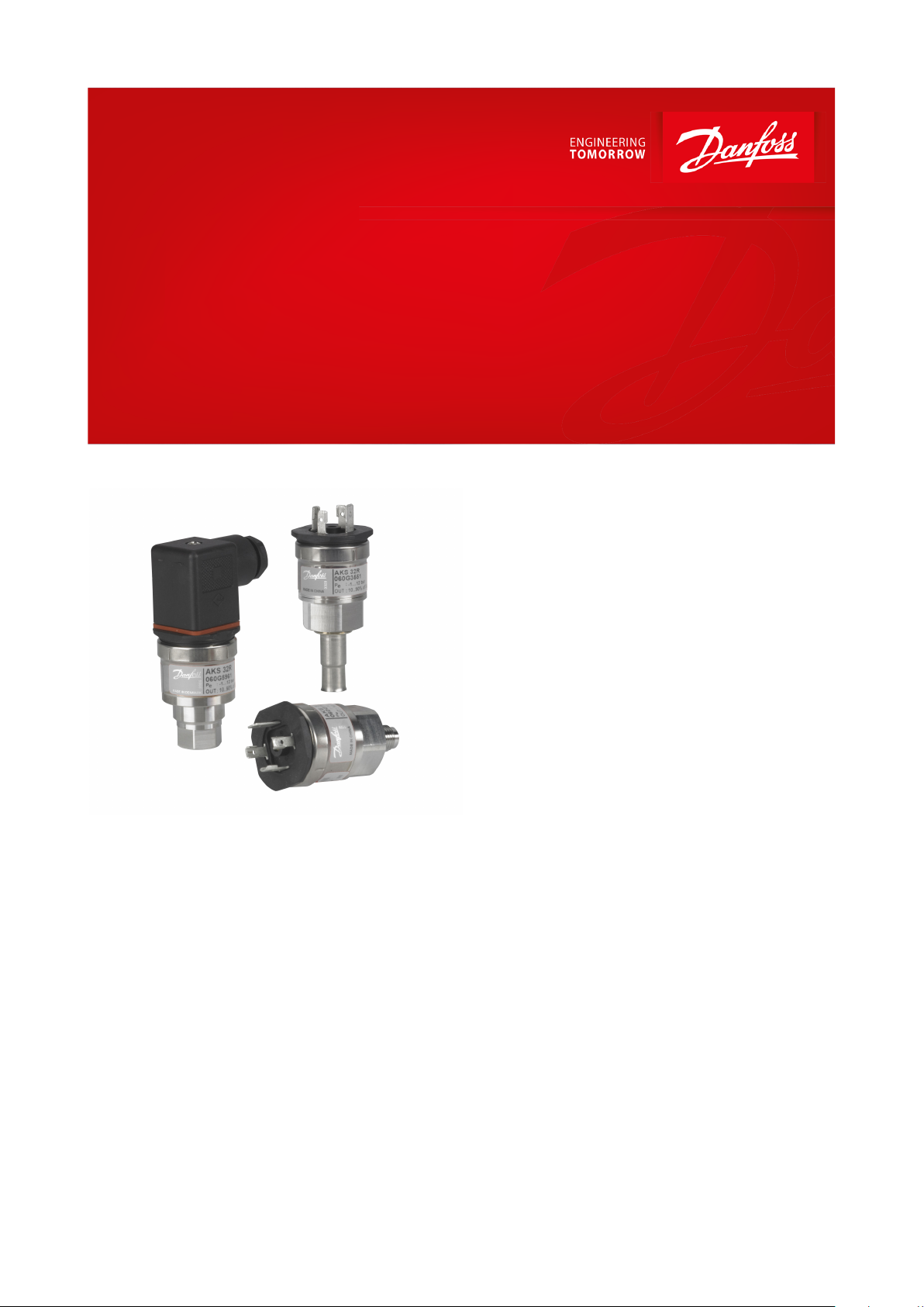
Pressure transmitter
Type AKS 32R and AKS 2050
AKS 32R is a ratiometric pressure transmitter
that converts the measured pressure to a linear
output signal. The output signal is relative to
the supply voltage meaning that the min.
pressure output will be 10% of the actual
supply voltage and the max. pressure output
will be 90% of the actual supply voltage.
At a supply voltage of 5 V, the output signal is:
• 0.5 V at min pressure range
• 4.5 V at max. pressure range
The robust design and the ratiometric output
signal makes the transmitter suitable for
systems together with ratiometric A/D
converters within a number of elds:
• A/C systems
• Refrigeration plant
• CO2 plant
• Process control
• Laboratories
Features
• Highly developed sensor technology means
great regulation accuracy
• Selective temperature compensation
• Compatible with all refrigerants incl.
ammonia and CO
• Robust construction gives protection against
mechanical inuences such as shock,
vibration, and pressure surge
• Polarity protected inlets
• Sealed gauge measuring principle (pressure
reference = 1013 mbar)
• For use in zone 2 explosive atmospheres
2
AI309145930291en-000301
Page 2

Features
Description
Accuracy (incl. Linearity, Hysteresis and repeatability)
± 0.3% FS (typ.)
± 0.8% FS (max.)
Non-linearity (best t straight line)
< ± 0.2% FS
Hysteresis and repeatability
≤ ± 0.1% FS
Thermal zero point operation
≤ ± 0.1% FS/10K (typ.)
≤ ± 0.2% FS/10K (max.)
Thermal sensitivity operation
≤ ± 0.1% FS/10K (typ.)
≤ ± 0.2% FS/10K (max.)
Response time
< 4 ms
Max. working pressure
See Dimensions and weight
Burst pressure
> 6 × FS
Power-up time
< 50 ms
Features
Description
Nominal output signal (short-circuit protection)
10 – 90% of [UB]
Supply voltage [UB] (polarity protected)
4.5 – 5.5 V DC at 5 V DC (nom.)
Power consumption
< 5 mA at 5 V DC
Ratiometricity
< 0.05% FS / 4.5 – 5.5 V
Sink / source
< 1 mA
Load [RL] (load connected to ground)
RL ≥ 10 kΩ at 5 V DC
Sensor operating
temperature range
Normal
-40 – 125 °C
ATEX Zone 2
-10 – 85 °C
Media temperature range
-40 – 125 °C
Compensated temperature range
See ordering
Transport / storage temperature range
-50 – 85 °C
EMC – Emission
EN 61000-6-3
EMC – Immunity
Electrostatic discharge
Air
8 kV
EN 61000-6-2
Contact
4 kV
EN 61000-6-2
RF
eld
10 V/m, 26 MHz – 1 GHz
EN 61000-6-2
conducted
3 V
rms
, 150 kHz – 30 MHz
EN 61000-6-2
Transient
Burst
4 kV (CM)
EN 61000-6-2
Surge
1 kV (CM, DM)
EN 61000-6-2
Insulation resistance
> 100 MΩ at 100 V DC
Vibration stability
Sinusoidal
20 g, 25 Hz – 2 kHz
IEC 60068-2-6
Random
7.5 g
rms
, 5 Hz – 1 kHz
IEC 60068-2-64
Shock resistance
Shock
500 g / 1 ms
IEC 60068-2-27
Free fall
1 m
IEC 60068-2-32
Enclosure (IP protection fullled together with mating connector)
IP65-IEC 60529
Pressure transmitter, AKS 32R and AKS 2050
Product specication
Technical data
Table 1: Performance (EN 60770)
Table 2: Electrical specications
Table 3: Environmental conditions
© Danfoss | Climate Solutions | 2021.02 AI309145930291en-000301 | 2
Page 3

Weight approx. 0.15 kg
22
17
26.5
19
21.8
hex 17
ø33
PR
TR
Ty
p
No.
L
40.5
Pressure connection
L [mm]
1
⁄4-18 NP
16
G
1
⁄2 A ISO 228/1
21
1
⁄4 in. are 7⁄16 - 20 UNF
16.5
3
⁄8 solder
30
7
⁄16 UNF are female with valve deator
21.5
Cable
Description
PG9
Description
Black: +
Blue: - / common
Brown: Signal
1: +
2: - / common
3: Signal
Pressure transmitter, AKS 32R and AKS 2050
Dimensions and weight
Table 4: Dimensions
Table 5: Dimensions and weight
Pulse-snubber, AKS 2050
Figure 1: Pulse-snubber
Cavitation, liquid hammer and pressure peaks may occur in liquid lled systems with changes in ow velocity, e.g.
fast closing of a valve or pump starts and stops.
The problem may occur on the inlet and outlet side, even at rather low operating pressures.
Plug connections
Table 6: Plug connections
© Danfoss | Climate Solutions | 2021.02 AI309145930291en-000301 | 3
Page 4

Zone 2 applications
EN60079-0; EN60079-15
Features
Description
AKS products can be used in end user applications employing the following ammable
refrigerants:
A3: R290, R600, R600a, R1270
A2L: R32, R444B, R452A/B, R454A/B/C, R455A, R1234zyef
IEC/EN 60335-2-89 (commercial refrigerating appliances)
IEC/EN 60335-2-40 (electrical heat pumps, air-onditioners)
Features
Descriptions
Electrical connection
EN 175301-803 plug / 2m cable
Wetted parts, material
EN10088-1-1.4404 (AISI 316L)
Housing material
EN10088-1-1.4404 (AISI 316L)
Refrigerants
DR3, DR55, DR7, HDR110, L40, R1234yf, R1234ze, R1270, R1290, R134a, R22, R227, R23, R290, R32, R404A,
R407A, R407B, R407C, R407F, R410A, R413A, R417A, R422A, R422D, R427A, R438A, R444B, R447A, R448A,
R449A, R449B, R450A, R452A/B, R454A/B/C, R455A, R502, R507, R513A, R600, R600a, R717 (NH3), R744 (CO2),
R1270
Type
Operating
range [bar]
Permissible
working pressure
PB [bar]
Compensated
temp. range [°C]
Code no.
¼ NPT
(1)
G
3
⁄8A
(2)
7
⁄16
in.
are
(3)
3
⁄8
solder
7/16-20
Female are
with
depressor
(5)
AKS 32R
-1 – 1233-30 – 40
060G1037
060G1038
060G1036
060G3551
060G6323
-1 – 1233-30 – 40
––060G6339
(4)
–
060G5961
(4)
-1 – 34550 – 80––
060G0090
060G3552
060G6341
-1 – 34550 – 80––
060G6340
(4)
–
–
AKS 2050
-1 – 59
100
-30 – 40
060G6342
060G5750
–
060G6408
–
-1 – 99
150
-30 – 40
060G6343
060G5751–––-1 – 159
250
0 – 80
060G6344
060G5752––
–
Connecting plug with 5 m cable (mounted on pressure transmitter
obtains IP67)
060G1034
–
Plug Pg 9
060G0008
–
Pressure transmitter, AKS 32R and AKS 2050
Explosive atmosphere
Table 7: Explosive atmospheres
The products for ATEX Zone 2 are applicable in refrigeration applications employing any ammable refrigerants
classied as IIA – please, refer to AKS installation guide. In ATEX Zone 2 applications at low temperatures cable and
plug must be protected against impact.
Table 8: Flammable refrigerants
For other products not ATEX Zone 2 assessed, an ignition risk assessment has been conducted with reference to
IEC/EN 60335-2-89 (commercial refrigerating appliances) and IEC/EN 60335-2-40 (electrical heat pumps, airconditioners).
For countries where safety standards are not an indispensable part of the safety system, Danfoss recommends the
installer to seek a third-party approval of the system containing ammable refrigerant. Note: Please, follow specic
selection criteria stated in the data sheet for these particular refrigerants.
Mechanical characteristics
Table 9: Mechanical characteristics
Ordering
Table 10: Ordering
© Danfoss | Climate Solutions | 2021.02 AI309145930291en-000301 | 4
Page 5

File name
Document type
Document topic
Approval Authority
E227388
Explosive - Safety Certicate
Hazardous Locations
UL
E31024
Electrical - Safety Certicate
UL
E311982
Electrical - Safety Certicate
UL
064G9615.06
EU Declaration
ATEX/EMCD/RoHS
Danfoss
060G9688.00
Manufacturers Declaration
Danfoss
F18477.5123467890YTN
Pressure - Safety Certicate
CRN
TSSA
060R3160.00
Manufacturers Declaration
China RoHS
Danfoss
064R9402.00
Manufacturers Declaration
PED
Danfoss
060R3162.00
Manufacturers Declaration
Danfoss
E494625
Electrical - Safety Certicate
UL
1786330
Explosive - Safety Certicate
CSA
Pressure transmitter, AKS 32R and AKS 2050
(1)
(1)
1/4-18 NPT
1/4-18 NPT
(2)
(2)
EN 837 - G 3/8 A
EN 837 - G 3/8 A
(3)
(3)
ISO 11926-
ISO 11926-
(4)
(4)
Incl. Plug connections
Incl. Plug connections
(5)
(5)
ISO 8434-1, 7/16-20 UNf, Female with depressor
ISO 8434-1, 7/16-20 UNf, Female with depressor
2
2
⁄3, 7⁄16 - 20 UNF Flare
⁄3, 7⁄16 - 20 UNF Flare
Certicates, declarations and approvals
The list contains all certicates, declarations, and approvals for this product type. Individual code number may have
some or all of these approvals, and certain local approvals may not appear on the list.
Some approvals may change over time. You can check the most current status at danfoss.com or contact your local
Danfoss representative if you have any questions.
Table 11: Certicates, declarations and approvals
© Danfoss | Climate Solutions | 2021.02 AI309145930291en-000301 | 5
Page 6

Online support
Danfoss oers a wide range of support along with our products, including digital product information, software,
mobile apps, and expert guidance. See the possibilities below.
The Danfoss Product Store
The Danfoss Product Store is your one-stop shop for everything product related—no matter where
you are in the world or what area of the cooling industry you work in. Get quick access to essential
information like product specs, code numbers, technical documentation, certications, accessories,
and more.
Start browsing at store.danfoss.com.
Find technical documentation
Find the technical documentation you need to get your project up and running. Get direct access to
our ocial collection of data sheets, certicates and declarations, manuals and guides, 3D models
and drawings, case stories, brochures, and much more.
Start searching now at www.danfoss.com/en/service-and-support/documentation.
Danfoss Learning
Danfoss Learning is a free online learning platform. It features courses and materials specically
designed to help engineers, installers, service technicians, and wholesalers better understand the
products, applications, industry topics, and trends that will help you do your job better.
Create your Danfoss Learning account for free at www.danfoss.com/en/service-and-support/learning.
Get local information and support
Local Danfoss websites are the main sources for help and information about our company and
products. Find product availability, get the latest regional news, or connect with a nearby expert—all
in your own language.
Find your local Danfoss website here: www.danfoss.com/en/choose-region.
Danfoss can accept no responsibility for possible errors in catalogues, brochures and other printed material. Danfoss reserves the right to alter its
products without notice. This also applies to products already on order provided that such alterations can be made without subsequential
changes being necessary in specications already agreed. All trademarks in this material are property of the respective companies. Danfoss and
the Danfoss logotype are trademarks of Danfoss A/S. All rights reserved.
© Danfoss | Climate Solutions | 2021.02 AI309145930291en-000301 | 6
 Loading...