

Page 1

Refrigeration and Air Conditioning Controls
Catalogue
Electronic controls
AKD 5000
ADAP-KOOL
Refrigeration control systems
®
Page 2

■ Contents
AKD 5000
Safety
Safety regulations ..................................................................................................... 4
Warning against unintended start ............................................................................. 4
...................................................................................................................... 3
Quick Setup ......................................................................................................... 6
AKD Lon card .......................................................................................................... 8
Introduction ....................................................................................................... 10
Ordering form AKD 5000 Series - Typecode ........................................................... 11
Technical data .................................................................................................. 12
General technical data ............................................................................................ 12
Electrical data ......................................................................................................... 16
Fuses ..................................................................................................................... 22
Mechanical dimensions .......................................................................................... 23
Installation ......................................................................................................... 25
Mechanical installation ............................................................................................ 25
Electrical installation - EMC precautions ................................................................. 31
Electrical installation, selection of EMC-correct cables ............................................ 33
Electrical installation - earthing of control cables ..................................................... 34
Electrical installation - mains supply ....................................................................... 35
Safety earthing ....................................................................................................... 35
Extra protection (RCD) ............................................................................................ 35
RFI switch .............................................................................................................. 35
Electrical installation - motor cables ....................................................................... 38
Connection of motor .............................................................................................. 38
Direction of motor rotation ...................................................................................... 38
Electrical installation - brake cable ......................................................................... 39
Electrical installation - relay outputs ....................................................................... 39
Electrical installation - bus connection ................................................................... 40
Electrical installation - control cables ...................................................................... 40
MG.50.R3.02 -
Operation of the AKD ................................................................................... 43
Control panel (LCP) ................................................................................................ 43
Control panel - display ............................................................................................ 43
Control panel - LEDs .............................................................................................. 43
Control panel - control keys .................................................................................... 44
Quick Setup ........................................................................................................... 46
Parameter selection ................................................................................................ 46
Menu mode ............................................................................................................ 47
Initialisation to factory setting .................................................................................. 48
Application configuration .......................................................................... 51
Setting of parameters ............................................................................................. 51
Special functions ............................................................................................ 52
Automatic Motor Adaptation, AMA ......................................................................... 52
1
Page 3

AKD 5000
PID for process control ........................................................................................... 54
Quick discharge ..................................................................................................... 55
Flying start .............................................................................................................. 56
Normal/high overload torque control, open loop ..................................................... 57
Programming of Torque limit and stop ................................................................... 58
Programming .................................................................................................... 59
Operation and Display ............................................................................................ 59
Parameters — Load and motor .............................................................................. 65
Parameters — References and limits ...................................................................... 72
Parameters — Inputs and outputs .......................................................................... 77
Parameters — Special functions ............................................................................. 87
Parameters — Serial communication ...................................................................... 93
Parameters — Technical functions and ................................................................... 97
Miscellaneous ................................................................................................ 101
Trouble-shooting .................................................................................................. 101
Display - Status messages ................................................................................... 102
Warnings and alarms ............................................................................................ 104
Warnings .............................................................................................................. 105
2
MG.50.R3.02 -
Page 4
AKD 5000
AKD 5000 Series
Operating instructions
Software version: 1.6x
These operating instructions can be used for all AKD 5000
Series frequency converters with software version 1.6x.
The software version number can be seen from parameter 624.
175ZA871.12
Safety
MG.50.R3.02 -
3
Page 5

The voltage of the frequency converter
is dangerous whenever the equipment
is connected to mains. Incorrect
installation of the motor or the frequency converter
may cause damage to the equipment, serious
personal injury or death.
Consequently, the instructions in this manual,
as well as national and local rules and safety
regulations, must be complied with.
■Safety regulations
1. The frequency converter must be disconnected
from mains if repair work is to be carried out. Check
that the mains supply has been disconnected
and that the necessary time has passed before
removing motor and mains plugs.
2. The [STOP/RESET] key on the control panel of
the frequency converter does not disconnect
the equipment from mains and is thus n
be used as a safety switch.
3. Correct protective earthing of the equipment
must be established, the user must be protected
against supply voltage, and the motor must be
protected against overload in accordance with
applicable national and local regulations.
4. The earth leakage currents are higher than 3.5 mA.
5. Protection against motor overload is not included
in the factory setting. If this function is desired,
set parameter 128 to data value ETR trip or
data value ETR warning.
N
ote: The function is initialised at 1.16 x rated
motor current and rated motor frequency. For
the North American market: The ETR functions
provide class 20 motor overload protection
in accordance with NEC.
6. Do n
7. Please note that the frequency converter has more
ot remove the plugs for the motor and main
supply while the frequency converter is connected
to mains. Check that the mains supply has been
disconnected and that the necessary time has
expired before removing motor and mains plugs.
voltage inputs than L1, L2 and L3, when loadsharing
(linking of DC intermediate circuit) and external 24 V
DC have been installed. Check that all voltage inputs
have been disconnected and that the necessary
time has passed before repair work is commenced.
ot to
AKD 5000
■Warning against unintended start
1. The motor can be brought to a stop by
means of digital commands, bus commands,
references or a local stop, while the frequency
converter is connected to mains.
If personal safety considerations make it necessary
to ensure that no unintended start occurs, t
stop functions are not sufficient.
2. While parameters are being changed, the
motor may start. Consequently, t
[STOP/RESET] must always be activated, following
which data can be modified.
3. A motor that has been stopped may start if faults
occur in the electronics of the frequency converter,
or if a temporary overload or a fault in the supply
mains or the motor connection ceases.
he stop key
hese
4
MG.50.R3.02 -
Page 6
AKD 5000
Warning:
It can be extremely dangerous to touch the electrical parts
even when the mains supply has been disconnected.
Also ensure that other voltage inputs are disconnected
from load sharing through the DC bus.
Wait at least 4 minutes after the input power has been
removed before servicing the drive.
195NA300.10
Safety
MG.50.R3.02 -
5
Page 7
AKD 5000
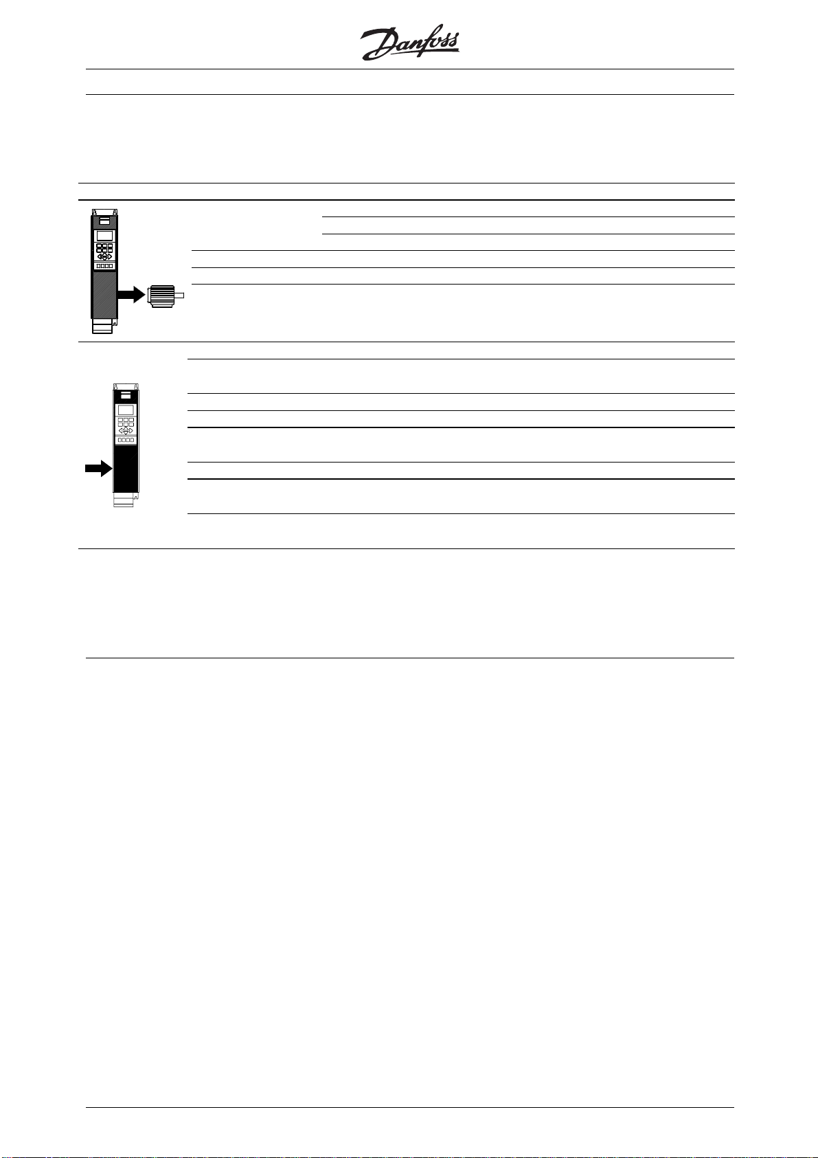
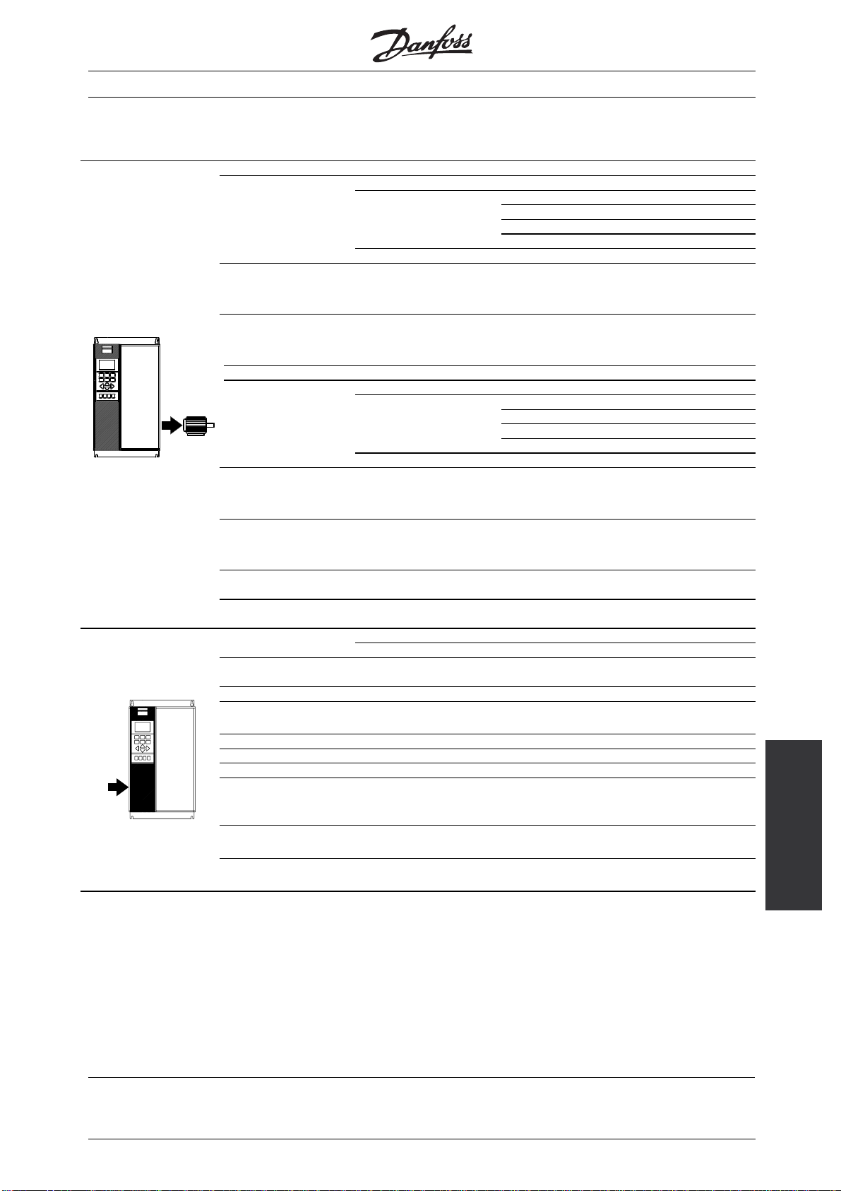
■Quick Setup
■Introduction to Quick Setup
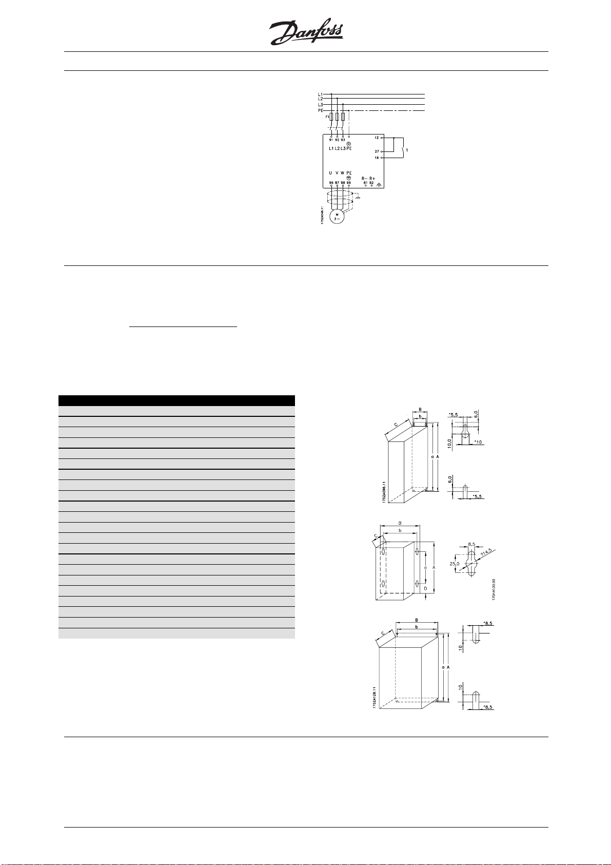
This Quick Setup will guide you through EMC correct
installation of the frequency converter by connecting
power, motor and control wiring (fig. 1). Start/stop
ofmotoristobedonewiththeswitch.
Fig. 1
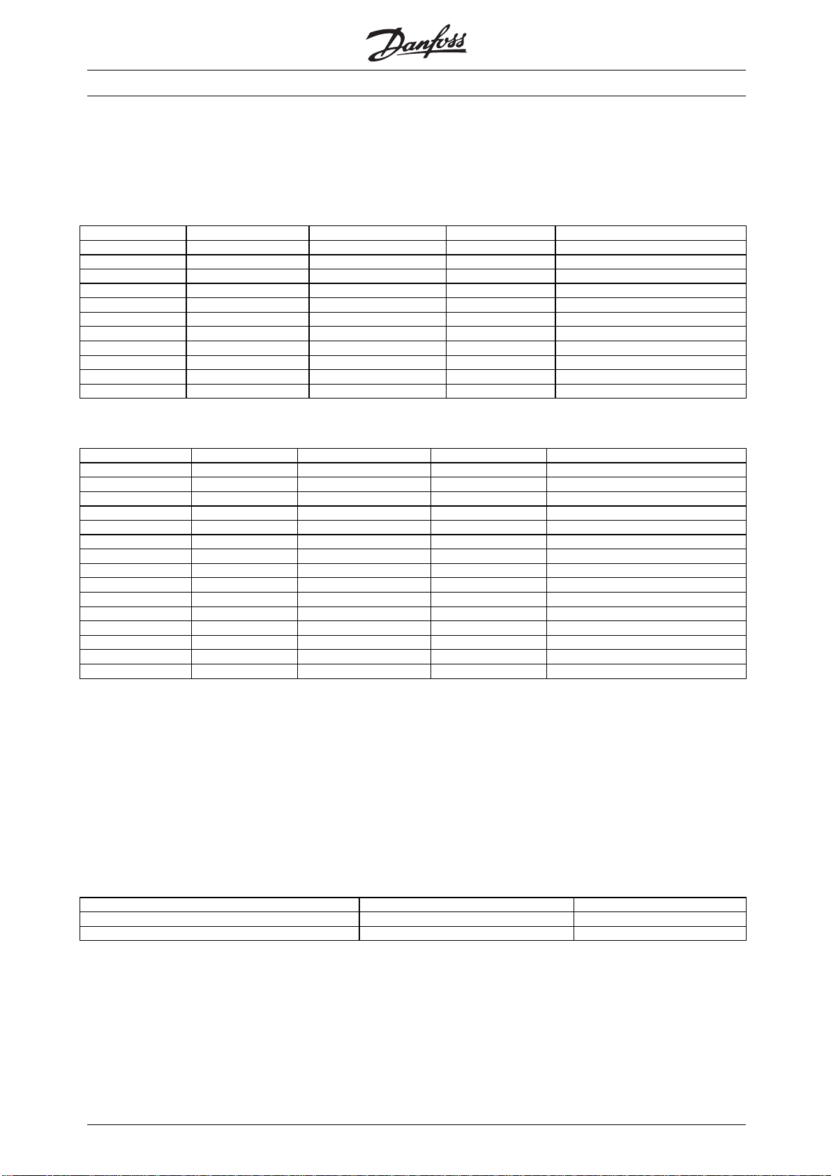
■1. Mechanical Installation
AKD 5000 frequency converters allow side-by-side mounting. The necessary cooling demands a free
air passage of 1
200-240 V must have 20 cm).
Drill all holes by using the measurements stated in the table. Please note the difference in unit voltage. Place
the frequency converter on the wall. Tighten up all four screws.
All the below listed measurements are in mm
0 cm above and below the frequency converter (5016-5062 380-500 V and 5008-5027
AKD type A B C a b
Compact IP 20, 200–240 V (Fig. 4)
5001 - 5003 395 220 160 384 200
5004 - 5006 395 220 200 384 200
5008 560 242 260 540 200
5011 - 5016 700 242 260 680 200
5022 - 5027 800 308 296 780 270
Compact IP 20, 380–500 V (Fig. 4)
5001 - 5005 395 220 160 384 200
5006 - 5011 395 220 200 384 200
5016 - 5022 560 242 260 540 200
5027 - 5032 700 242 260 680 200
Compact IP 54, 200–240 V (Fig. 3)
5001 - 5003 460 282 195 260 258
5004 - 5006 530 282 195 330 258
5008 - 5011 810 350 280 560 326
5016 - 5027 940 400 280 690 375
Compact IP 54, 380–500 V (Fig. 3)
5001 - 5005 460 282 195 260 258
5006 - 5011 530 282 195 330 258
5016 - 5027 810 350 280 560 326
5032 - 5062 940 400 280 690 375
5042 - 5062 800 308 296 780 270
Fig. 2
Fig. 3
Fig. 4
6
MG.50.R3.02 -
Page 8

AKD 5000
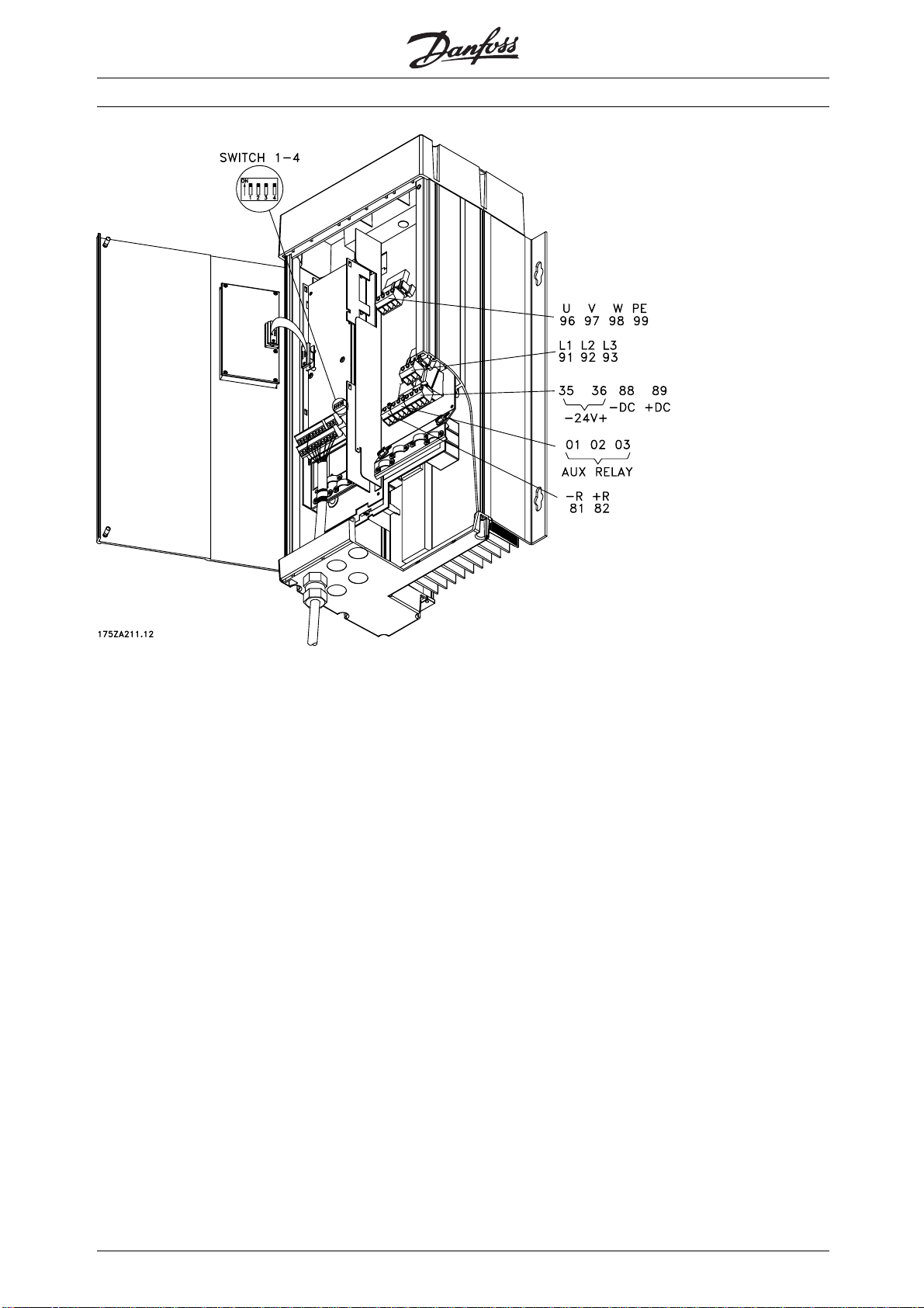
■2. Electrical Installation, power
NOTE: The terminals are detachable on AKD 5001-5006, 200-240 V and AKD 5001-5011, 380-500 V
Connect the mains supply to the mains terminals L1, L2, L3 of the frequency converter and to the earth
connection (fig. 5-8). Cable relief fitting is placed on the wall for Bookstyle units. Mount screened motor
cable to the motor terminals U, V, W, PE of the frequency converter. Make sure, the screen is connected
electrically to the drive.
Fig. 6
C
ompact IP 20 and IP 54
5001 - 5011 380 - 500 V
5001 - 5006 200 - 240 V
Fig. 7
C
ompact IP 20
5016 - 5062 380 - 500 V
5008 - 5027 200 - 240 V
Quick
Setup
MG.50.R3.02 -
7
Page 9
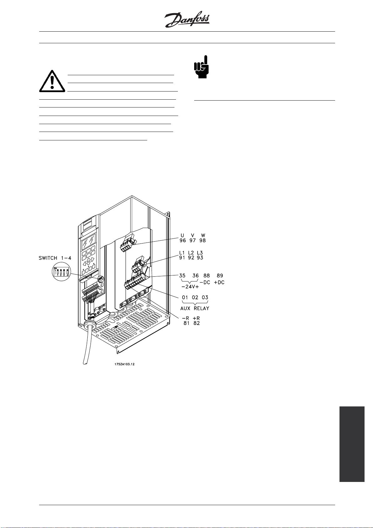
■3. Electrical installation, control leads
Use a screw driver to remove the front cover
under the control panel.
NOTE: The terminals are detachable. Connect a
jumber between terminals 12 and 27 (Fig. 10)
Mount screened cable to external start/stop of
control terminals 12 and 18.
AKD 5000
Fig. 10
■4. Programming
The frequency converter is programmed over
the control panel.
Press the QUICK MENU button. The Quick Menu
appears in the display. You choose parameters by
means of arrow up and arrow down. Press the
CHANGE DATA button to change parameter value.
Data values are changed using the up and down
arrows. Press the left or right buttons to move the
cursor. Press OK to save your parameter setting.
Set the desired language in parameter 001. You
have six possibilities: English, German, French,
Danish, Spanish and Italian.
Set the motor parameters according to the motorplate:
Motor power
Motor voltage
Motor frequency
Motor current
Rated motor speed
Parameter 102
Parameter 103
Parameter 104
Parameter 105
Parameter 106
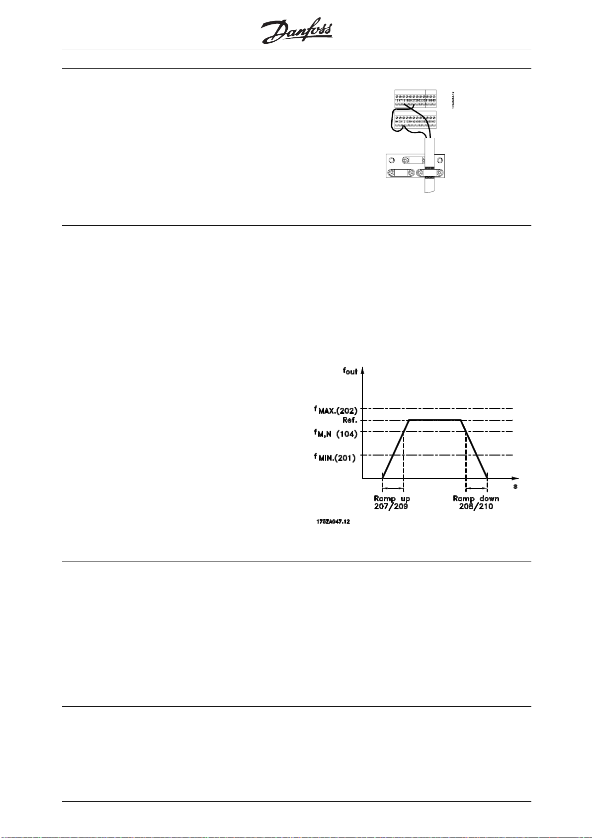
Set frequency interval and ramp times (Fig. 11)
Min. reference
Max. reference
Ramp up time
Ramp down time
Set Operation site, Parameter 002 for Local.
Parameter 204
Parameter 205
Parameter 207
Parameter 208
■5. Motor Start
Press the START button to start the motor. Set motor
speed in Parameter 003. Check if the direction of
rotations is as shown in the display. It can be changed
by swapping two phases of the motor cable.
Press the STOP button to stop the motor.
■AKD Lon card
Requirements:
AKD 2800 must have software version (par
624) 1.32 or higher
AKD 5000 must have software version (par
624) 1.52 or higher
8
Fig. 11
Select total or reduced Automatic Motor Adaption
(AMA) in Parameter 107. For further description of
AMA, see section Automatic Motor Adaption, AMA.
Press the START button to start the Automatic
Motor Adaption (AMA).
Press the DISPLAY/STATUS button to leave
the Quick Menu.
The AKD Lon card is RS485 based and must connect
to an RS485 Adap-Kool Lon network.
The card can be ordered as build-in with the AKD5000
and comes in an external box for the AKD2800.
MG.50.R3.02 -
Page 10
AKD 5000
AKD Lon connections:
The Lon card has two connections.
AKD-Connections:
Lon card terminals 1
(Red +24V)
(White or Yellow
A 6-pole connector (only 1-4 is used) that connects
to the AKD. Connections are as follows:
2
3
(Black Com)
(Green TX+, RX+)
TX-, RX-)
AKD terminals 12 69 39 or 20 68
The 3-pole connector for the Lon Communication:
Lon card terminals 1 2 3
Adap-Kool Lon A B Shield
Connect the Adap-Kool Lon network to the removable
3-postion connector. Be careful to route the network
wires away from the AC power and motor wires.
Commissioning
Upon power up the lower red LED of the double LED’s,
next to the Lon connectors will initially be flashing red.
1. Set AKD address in parameter 500 in
the AKD (1 to 60)
2. Wait for about 1 min until the red LED goes
off. (card initialisation)
3. Press one of the service pin buttons
4. Wait for about 2 minutes (upload of
parameters to gateway)
5. Perform a "Net configuration" upload in AKM
and you should now find the AKD. Perform a
"AKC description" upload in AKM
6. Go to menu AKC -> Controllers in AKM and
youshouldfindtheAKD
4
Quick
Setup
MG.50.R3.02 -
9
Page 11
AKD 5000
■Introduction
These Operating Instructions are a tool intended for persons who are to install, operate and program the
AKD 5000 Series.
When reading these Operating Instructions, you will come across different symbols that require special
attention.
The symbols used are the following:
Indicates a general warning
NB!:
Indicates something to be noted by the reader
Indicates a high-voltage warning
10
MG.50.R3.02 -
Page 12
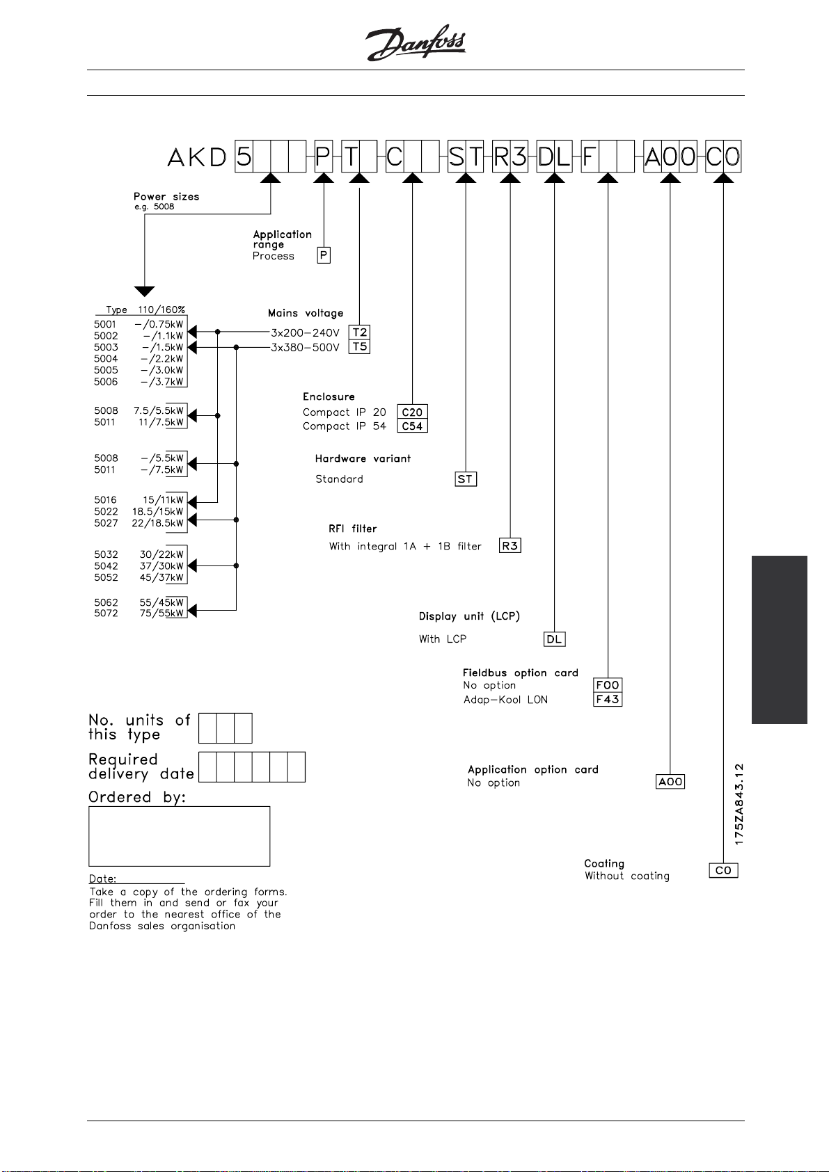
■Ordering form AKD 5000 Series - Typecode
AKD 5000
Introduction
MG.50.R3.02 -
11
Page 13

AKD 5000
■General technical dat a
Mains supply (L1, L2, L3):
Supply voltage 200-240 V units ........................................................................ 3 x 200/208/220/230/240 V ±10%
Supply voltage 380-500 V units ................................................................ 3 x 380/400/415/440/460/500 V ±10%
Supply frequency ......................................................................................................................... 48/62 Hz +/- 1%
AKD 5001-5011, 380-500 V and AKD 5001-5006, 200-240 V ............................... ±2.0% of rated supply voltage
AKD 5016-5062, 380-500 V and AKD 5008-5027, 200-240 V ............................... ±1.5% of rated supply voltage
True Power factor (λ) ...................................................................................................... 0.90 nominal at rated load
Displacement Power Factor (cos φ) .............................................................................................. near unity (>0.98)
No. of switchings on supply input L1, L2, L3 .......................................................................... approx. 1 time/min.
See the section on special conditions in the Design Guide
AKD output data (U, V, W):
Output voltage ................................................................................................................ 0-100% of supply voltage
Output frequency .................................................................................................................. 0-132 Hz, 0-1000 Hz
Rated motor voltage, 200-240 V units .............................................................................. 200/208/220/230/240V
Rated motor voltage, 380-500 V units ............................................................... 380/400/415/440/460/480/500 V
Rated motor frequency ............................................................................................................................ 50/60 Hz
Switching on output ................................................................................................................................. Unlimited
Ramp times .................................................................................................................................... 0.05-3600 sec.
Torque characteristics:
Starting torque, AKD 5001-5027, 200-240 V and AKD 5001-5062, 380-500 V ............................. 160% for 1 min.
Starting torque ............................................................................................................................ 180% for 0.5 sec.
Acceleration torque ....................................................................................................................................... 100%
Overload torque, AKD 5001-5027, 200-240 V and AKD 5001-5062, 380-500 V .......................................... 160%
Arresting torque at 0 rpm (closed loop) ......................................................................................................... 100%
The torque characteristics given are for the frequency converter at the high overload torque level
(160%). At the normal overload torque (110%), the values are lower.
Control card, digital inputs:
Number of programmable digital inputs ................................................................................................................ 8
Terminal nos. ............................................................................................................ 16, 17, 18, 19, 27, 29, 32, 33
Voltage level ........................................................................................................... 0-24 V DC (PNP positive logics)
Voltage level, logical ’0’ ............................................................................................................................ < 5 V DC
Voltage level, logical ’1’ ........................................................................................................................... >10 V DC
Maximum voltage on input ........................................................................................................................ 28 V DC
Input resistance, R
........................................................................................................................................ 2 k
i
Scanning time per input ............................................................................................................................. 3 msec.
Reliable galvanic isolation: All digital inputs are galvanically isolated from the supply voltage (PELV).
In addition, the digital inputs can be isolated from the other terminals on t
he control card by
connecting an external 24 V DC supply and opening switch 4.
Control card, analogue inputs:
No. of programmable analogue voltage inputs/thermistor inputs .......................................................................... 2
Terminal nos. ................................................................................................................................................ 53, 54
Voltage level ........................................................................................................................ 0 - ±10 V DC (scalable)
Input resistance, R
...................................................................................................................................... 10 k
i
No. of programmable analogue current inputs ..................................................................................................... 1
Terminal no. ........................................................................................................................................................ 60
Current range .................................................................................................................... 0/4 - ±20 mA (scalable)
Input resistance, R
...................................................................................................................................... 200
i
Resolution .......................................................................................................................................... 10 bit + sign
12
MG.50.R3.02 -
Page 14

AKD 5000
Accuracy on input .......................................................................................................... Max. error 1% of full scale
Scanning time per input ............................................................................................................................. 3 msec.
Terminal no. ground ............................................................................................................................................ 55
Reliable galvanic isolation: All analogue inputs are galvanically isolated from the supply voltage
(PELV) as well as other inputs and outputs.
Control card, pulse/encoder input:
No. of programmable pulse/encoder inputs .......................................................................................................... 4
Terminal nos. .................................................................................................................................... 17, 29, 32, 33
Max. frequency on terminal 17 ...................................................................................................................... 5 kHz
Max. frequency on terminals 29, 32, 33 ...................................................................... 20 kHz (PNP open collector)
Max. frequency on terminals 29, 32, 33 ..................................................................................... 65 kHz (Push-pull)
Voltage level ........................................................................................................... 0-24 V DC (PNP positive logics)
Voltage level, logical ’0’ ............................................................................................................................ < 5 V DC
Voltage level, logical ’1’ ........................................................................................................................... >10 V DC
Maximum voltage on input ........................................................................................................................ 28 V DC
Input resistance, R
Scanning time per input ............................................................................................................................. 3 msec.
Resolution .......................................................................................................................................... 10 bit + sign
Accuracy (100-1 kHz), terminals 17, 29, 33 ............................................................... Max. error: 0.5% of full scale
Accuracy (1-5 kHz), terminal 17 ................................................................................. Max. error: 0.1% of fullscale
Accuracy (1-65 kHz), terminals 29, 33 ....................................................................... Max. error: 0.1% of full scale
Reliable galvanic isolation: All pulse/encoder inputs are galvanically isolated from the supply voltage
(PELV). In addition, pulse and encoder inputs can be isolated from the other terminals on the control
card by connecting an external 24 V DC supply and opening switch 4.
See section on Control cables.
........................................................................................................................................ 2 k
i
Control card, digital/pulse and analogue outputs:
No. of programmable digital and analogue outputs .............................................................................................. 2
Terminal nos. ................................................................................................................................................ 42, 45
Voltage level at digital/pulse output ...................................................................................................... 0 - 24 V DC
Minimum load to ground (terminal 39) at digital/pulse output ....................................................................... 600
Frequency ranges (digital output used as pulse output) ............................................................................ 0-32 kHz
Current range at analogue output ........................................................................................................ 0/4 - 20 mA
Maximum load to ground (terminal 39) at analogue output ........................................................................... 500
Accuracy of analogue output ..................................................................................... Max. error: 1.5% of full scale
Resolution on analogue output. ....................................................................................................................... 8 bit
Reliable galvanic isolation: All digital and analogue outputs are galvanically isolated from the
supply voltage (PELV), as well as other inputs and outputs.
Control card, 24 V DC supply:
Terminal nos. ................................................................................................................................................ 12, 13
Max. load (short-circuit protection) ............................................................................................................. 200 mA
Terminal nos. ground .................................................................................................................................... 20, 39
Reliable galvanic isolation: The 24 V DC supply is galvanically isolated from th
(PELV), but has the same potential as the analogue outputs.
Control card, RS 485 serial communication:
Terminal nos. .............................................................................................................. 68 (TX+, RX+), 69 (TX-, RX-)
Reliable galvanic isolation: Full galvanic isolation.
e supply voltage
data
Technical
Relay outputs:
No. of programmable relay outputs ...................................................................................................................... 2
MG.50.R3.02 -
13
Page 15

AKD 5000
Terminal nos., control card ..................................................................................................................... 4-5 (make)
Max. terminal load (AC) on 4-5, control card .......................................................................... 50 V AC, 1 A, 50 VA
Max. terminal load (DC-1 (IEC 947)) on 4-5, control card ......................................................... 75 V DC, 1 A, 30 W
Max. terminal load (DC-1) on 4-5, control card for UL/cUL applications ................... 30 V AC, 1 A / 42.5 V DC, 1A
Terminal nos., power card ................................................................................................... 1-3 (break), 1-2 (make)
Max. terminal load (AC) on 1-3, 1-2, power card ................................................................. 240 V AC, 2 A, 60 VA
Max. terminal load DC-1 (IEC 947) on 1-3, 1-2, power card .............................................................. 50 V DC, 2 A
Min. terminal load on 1-3, 1-2, power card ........................................................ 24 V DC 10 mA, 24 V AC 100 mA
External 24 Volt DC supply:
Terminal nos. ................................................................................................................................................ 35, 36
Voltage range ....................................................................................... 24 V DC ±15% (max. 37 V DC for 10 sec.)
Max. voltage ripple ..................................................................................................................................... 2 V DC
Power consumption .............................................................................. 15 W - 50 W (50 W for start-up, 20 msec.)
Min. pre-fuse ............................................................................................................................................... 6 Amp
Reliable galvanic isolation: Full galvanic isolation if the external 24 V DC supply is also of the PELV type.
Cable lengths, cross-sections and connectors:
Max. motor cable length, screened cable ..................................................................................................... 150 m
Max. motor cable length, unscreened cable ................................................................................................. 300 m
Max. motor cable length, screened cable AKD 5011 380-500 V ................................................................... 100 m
Max. brake cable length, screened cable ........................................................................................................ 20 m
Max. loadsharing cable length, screened cable ..................................... 25 m from frequency converter to DC bar.
Max. cable cross-section for motor, brake and loadsharing, see next section
Max. cable cross-section for 24 V external DC supply .............................................................. 4.0 mm
Max. cross-section for control cables ....................................................................................... 1.5 mm
Max. cross-section for serial communication ............................................................................ 1.5 mm
If UL/cUL is to be complied with, cable with temperature class 60/75°C must be used
(AKD 5001-5062 380-500 V and AKD 5001-5027 200-240 V).
2
/10 AWG
2
/16 AWG
2
/16 AWG
Accuracy of display readout (parameters 009-012):
Motor current [6] 0-140% load ............................................................... Max. error: ±2.0% of rated output current
Torque % [7], -100 - 140% load ...................................................................... Max. error: ±5% of rated motor size
Output [8], power HP [9], 0-90% load ................................................................... Max. error: ±5% of rated output
Control characteristics:
Frequency range .................................................................................................................................. 0 - 1000 Hz
Resolution on output frequency ............................................................................................................. ±0.003 Hz
System response time ............................................................................................................................... 3 msec.
Speed, control range (open loop) ..................................................................................... 1:100 of synchro. speed
Speed, control range (closed loop) ................................................................................. 1:1000 of synchro. speed
Speed, accuracy (open loop) ............................................................................ < 1500 rpm: max. error ± 7.5 rpm
..................................................................................................... >1500 rpm: max. error of 0.5% of actual speed
Speed, accuracy (closed loop) .......................................................................... < 1500 rpm: max. error ± 1.5 rpm
..................................................................................................... >1500 rpm: max. error of 0.1% of actual speed
Torque control accuracy (open loop) ................................................ 0- 150 rpm: max. error ±20% of rated torque
................................................................................................... 150-1500 rpm: max. error ±10% of rated torque
........................................................................................................ >1500 rpm: max. error ±20% of rated torque
Torque control accuracy (speed feedback) ............................................................. Max. error ±5% of rated torque
All control characteristics are based on a 4-pole asynchronous motor
14
MG.50.R3.02 -
Page 16

AKD 5000
Externals:
Enclosure ............................................................................................................................................. IP 20, IP 54
Vibration test .................................. 0.7 g RMS 18-1000 Hz random. 3 directions for 2 hours (IEC 68-2-34/35/36)
Max. relative humidity ................................................................................ 93 % (IEC 68-2-3) for storage/transport
Max. relative humidity ............................................... 95 % non condensing (IEC 721-3-3; class 3K3) for operation
Aggresive environment (IEC 721 - 3 - 3) .................................................................................. Uncoated class 3C2
Aggresive environment (IEC 721 - 3 - 3) ...................................................................................... Coated class 3C3
Ambient temperature IP 20 (high overload torque 160%) ....................... Max. 45°C (24-hour average max. 40°C)
Ambient temperature IP 20 (normal overload torque 110%) .................... Max. 40°C (24-hour average max. 35°C)
Ambient temperature IP 54 (high overload torque 160%) ....................... Max. 40°C (24-hour average max. 35°C)
Ambient temperature IP 54 (normal overload torque 110%) .................... Max. 40°C (24-hour average max. 35°C)
Ambient temperature IP 20/54 AKD 5011 500 V .................................... Max. 40°C (24-hour average max. 35°C)
Derating for high ambient temperature, see the Design Guide
Min. ambient temperature in full operation ........................................................................................................ 0°C
Min. ambient temperature at reduced performance ..................................................................................... -10°C
Temperature during storage/transport ............................................................................................. -25 - +65/70°C
Max. altitude above sea level ...................................................................................................................... 1000 m
Derating for high air altitude, see the Design Guide
EMC standards applied, Emission .............................................................. EN 50081-1/2, EN 61800-3, EN 55011
EMC standards applied, Immunity .......................... EN 61000-6-2, EN 61000-4-2, EN 61000-4-3, EN 61000-4-4
EN 61000-4-5, EN 61000-4-6, VDE 0160/1990.12
See section on special conditions in the Design Guide.
AKD 5000 Series protection:
• Electronic motor thermal protection against overload.
• Temperature monitoring of heat-sink ensures that the frequency converter cuts out if the temperature
reaches 90°C for IP 20. For IP 54, the cut-out temperature is 80°C. An overtemperature can only
be reset when the temperature of the heat-sink has fallen below 60°C.
• The frequency converter is protected against short-circuiting on motor terminals U, V, W.
• The frequency converter is protected against earth fault on motor terminals U, V, W.
• Monitoring of the intermediate circuit voltage ensures that the frequency converter cuts out if
the intermediate circuit voltage gets too high or too low.
• If a motor phase is missing, the frequency converter cuts out.
• If there is a mains fault, the frequency converter is able to carry out a controlled decelleration.
• If a mains phase is missing, the frequency converter will cut out when a load is placed on the motor.
data
Technical
MG.50.R3.02 -
15
Page 17
■Electrical data
■Compact,Mainssupply3x200-240V
AKD 5000
According to international requirements AAAAKKKKDDDDttttyyyyppppeeee555500000000111155550000000022225
55500000000333
Output current IN[A] 3.7 5.4 7.8 10.6 12.5 15.2
I
(60 s) [A] 5.9 8.6 12.5 17 20 24.3
MAX
Output (240 V) SN[kVA] 1.5 2.2 3.2 4.4 5.2 6.3
Ty pi ca l s ha f t out pu t PN[kW] 0.75 1.1 1.5 2.2 3.0 3.7
Ty pi ca l s ha f t out pu t PN[HP]11.52345
Max. cable cross-section to motor,
brake and loadsharing [mm2]/[AWG]2)
Rated input current (200 V)I
Max. cable
cross-section power [mm2]/[AWG]2)
L,N
4/10 4/10 4/10 4/10 4/10 4/10
[A] 3.4 4.8 7.1 9.5 11.5 14.5
4/10 4/10 4/10 4/10 4/10 4/10
Max. pre-fuses [-]/UL1)[A] 16/10 16/10 16/15 25/20 25/25 35/30
Efficiency
Weight IP 20 EB
Compact
3)
0.95 0.95 0.95 0.95 0.95 0.95
[kg] 8 8 8 10 10 10
Weight IP 54 Compact [kg] 11.5 11.5 11.5 13.5 13.5 13.5
Power loss at
max. load.
Enclosure
[W] 58 76 95 126 172 194
IP 20/
IP54
IP 20/
IP54
IP 20/
IP54
1. For type of fuse see section Fuses.
2. American Wire Gauge.
3. Measured using 30 m screened motor cables at rated load and rated frequency.
35
55500000000444
IP 20/
IP54
45
55500000000555
IP 20/
IP54
55
55500000000666
IP 20/
IP54
6
16
MG.50.R3.02 -
Page 18
■Compact,Mainssupply3x200-240V
AKD 5000
According to international requirements AAAAKKKKDDDDttttyyyyppppeeee5
85
55500000000888
55500001111111
NNNNoooorrrrmmmmaaaalllloooovvvveeeerrrrllllooooaaaaddddttttoooorrrrqqqquuuueeee((((111111110000%%%%))))::::
Output current IN[A] 324661.27388
I
(60 s) [A] 35.2 50.6 67.3 80.3 96.8
MAX
Output (240 V) SN[kVA] 13.3 19.1 25.4 30.3 36.6
Ty pi ca l s ha f t out pu t PN[kW] 7.5 11 15 18.5 22
Ty pi ca l s ha f t out pu t PN[HP] 10 15 20 25 30
HHHHiiiigggghhhhoooovvvveeeerrrrllllooooaaaaddddttttoooorrrrqqqquuuueeee((((111166660000%%%%))))::::
Output current IN[A] 25324661.273
I
(60 s) [A] 40 51.2 73.6 97.9 116.8
MAX
Output (240 V) SN[kVA] 1013192530
Ty pi ca l s ha f t out pu t PN[kW] 5.5 7.5 11 15 18.5
Ty pi ca l s ha f t out pu t PN[HP] 7.5 10 15 20 25
Max. cable cross-section to motor, IP 54 16/6 16/6 35/2 35/2 50/0
brake and loadsharing [mm
2
Min. cable cross-section to motor,
brake and loadsharing
4)
[mm2/AWG]
Rated input current (200 V) I
2)5)
/AWG]
L,N
IP 20 16/6 35/2 35/2 35/2 50/0
2)
10/8 10/8 10/8 10/8 16/6
[A] 3246617388
Max. cable cross-section, IP 54 16/6 16/6 35/2 35/2 50/0
power [mm
2
]/[AWG]
2)5)
IP 20 16/6 35/2 35/2 35/2 50/0
Max. pre-fuses [-]/UL1)[A] 50 60 80 125 125
Pre-fuse SMPS [-]/UL6)) [A] 4.0/4.0 4.0/4.0 4.0/4.0 4.0/4.0 4.0/4.0
Efficiency
3)
0.95 0.95 0.95 0.95 0.95
Weight IP 20 EB [kg] 21 25 27 34 36
Weight IP 54 [kg] 38 40 53 55 56
Power loss at max. load.
-highoverloadtorque
(160 %)
-normaloverload
torque (110 %)
Enclosure
[W]
[W]
340 426 626 833 994
426 545 783 1042 1243
IP 20/
IP 54
IP 20/
IP 54
15
55500001111666
IP 20/
IP 54
65
55500002222222
IP 20/
IP 54
25
55500002222777
IP 20/
IP 54
7
1. For type of fuse see section Fuses
2. American Wire Gauge.
3. Measured using 30 m screened motor cables at rated load and rated frequency.
4. Min. cable cross-section is the smallest cable cross-section allowed to be fitted on the terminals to comply with IP 20.
Always comply with national and local regulations on min. cable cross-section.
5. Aluminium cables with cross-section above 35 mm
2
must be connected by use of a AI-Cu connector.
6. If UL/cUL is to be complied with, Ferraz Shawmut type Y85443, Danfoss ordering no. 612Z1182 must be used.
MG.50.R3.02 -
data
Technical
17
Page 19
■Compact,Mainssupply3x380-500V
AKD 5000
According to international requirements AAAAKKKKDDDDttttyyyyppppeeee555500000000111155550000000022225
55500000000333
Output current IN[A] (380-440 V) 2.2 2.8 4.1 5.6
I
(60 s) [A] (380-440 V) 3.5 4.5 6.5 9
MAX
IN[A] (441-500 V) 1.9 2.6 3.4 4.8
I
(60 s) [A] (441-500 V) 3 4.2 5.5 7.7
MAX
Output SN[kVA] (380-440 V) 1.7 2.1 3.1 4.3
SN[kVA] (441-500 V) 1.6 2.3 2.9 4.2
Typical shaft output PN[kW] 0.75 1.1 1.5 2.2
Typical shaft output PN[HP] 1 1.5 2 3
Max. cable cross-section to motor,
2
brake and loadsharing [mm
]/[AWG]2)
Rated input current I
Max. cable cross-section, power [mm2]/[AWG]
[A] (380 V) 2.3 2.6 3.8 5.3
L,N
I
[A] (460 V) 1.9 2.5 3.4 4.8
L,N
2)
4/10 4/10 4/10 4/10
4/10 4/10 4/10 4/10
Max. pre-fuses [-]/UL1)[A] 16/6 16/6 16/10 16/10
Efficiency
3)
0.96 0.96 0.96 0.96
Weight IP 20 EB Compact [kg] 8 8 8 8.5
Weight IP 54 Compact [kg] 11.5 11.5 11.5 12
Power loss at max. load [W] 55 67 92 110
Enclosure
IP 20
IP 54
IP 20
IP 54
IP 20
IP 54
35555000000004444
IP 20
IP 54
1. For type of fuse see section Fuses.
2. American Wire Gauge.
3. Measured using 30 m screened motor cables at rated load and rated frequency.
18
MG.50.R3.02 -
Page 20
Compact, Mains supply 3 x 380 - 500 V
AKD 5000
According to international requirements AAAAKKKKDDDDttttyyyyppppeeee55550000000055555
65
55500000000666
Output current IN[A] (380-440 V) 7.2 10 13 16
I
(60 s) [A] (380-440 V) 11.5 16 20.8 25.6
MAX
IN[A] (441-500 V) 6.3 8.2 11 14.5
I
(60 s) [A] (441-500 V) 10.1 13.1 17.6 23.2
MAX
Output SN[kVA] (380-440 V) 5.5 7.6 9.9 12.2
SN[kVA] (441-500 V) 5.5 7.1 9.5 12.6
Typical shaft output PN[kW] 3.0 4.0 5.5 7.5
Typical shaft output PN[HP] 4 5 7.5 10
Max. cable cross-section to motor,
brake and loadsharing [mm2]/[AWG]2)
Rated input current I
L,N
I
L,N
Max. cable cross-section power [mm2]/[AWG]
[A] (380 V) 7 9.1 12.2 15.0
[A] (460 V) 6 8.3 10.6 14.0
2)
4/10 4/10 4/10 4/10
4/10 4/10 4/10 4/10
Max. pre-fuses [-]/UL1)[A] 16/15 25/20 25/25 35/30
Efficiency
3)
0.96 0.96 0.96 0.96
Weight IP 20 EB Compact [kg] 8.5 10.5 10.5 10.5
Weight IP 54 EB Compact [kg] 12 14 14 14
Power loss at max.
load.
Enclosure
[W]
139 198 250 295
IP 20/
IP 54
IP 20/
IP 54
85
55500000000888
IP 20/
IP 54
1
55500001111111
IP 20/
IP 54
1. For type of fuse see section Fuses.
2. American Wire Gauge.
3. Measured using 30 m screened motor cables at rated load and rated frequency.
data
Technical
MG.50.R3.02 -
19
Page 21
■Compact,Mainssupply3x380-500V
AKD 5000
According to international requirements AAAAKKKKDDDDttttyyyyppppeeee5
65
55500001111666
55500002222222
NNNNoooorrrrmmmmaaaalllloooovvvveeeerrrrllllooooaaaaddddttttoooorrrrqqqquuuueeee((((111111110000%%%%))))::::
Output current IN[A] (380-440 V) 32 37.5 44
I
(60 s) [A] (380-440 V) 35.2 41.3 48.4
MAX
IN[A] (441-500 V) 27.9 34 41.4
I
(60 s) [A] (441-500 V) 30.7 37.4 45.5
MAX
Output SN[kVA] (380-440 V) 24.4 28.6 33.5
SN[kVA] (441-500 V) 24.2 29.4 35.8
Typical shaft output PN[kW] 15 18.5 22
Typical shaft output PN[HP] 20 25 30
HHHHiiiigggghhhhoooovvvveeeerrrrllllooooaaaaddddttttoooorrrrqqqquuuueeee((((111166660000%%%%))))::::
Output current IN[A] (380-440 V) 24 32 37.5
I
(60 s) [A] (380-440 V) 38.4 51.2 60
MAX
IN[A] (441-500 V) 21.7 27.9 34
I
(60 s) [A] (441-500 V) 34.7 44.6 54.4
MAX
Output SN[kVA] (380-440 V) 18.3 24.4 28.6
SN[kVA] (441-500 V) 18.8 24.2 29.4
Typical shaft output PN[kW] 11 15 18.5
Typical shaft output PN[HP] 15 20 25
Max. cable cross-section to motor, IP 54 16/6 16/6 16/6
brake and loadsharing [mm2]/[AWG]
2) 4)
IP 20 16/6 16/6 35/2
Min. cable cross-section to motor,
brake and loadsharing [mm2]/[AWG] 10/8 10/8 10/8
Rated input current I
[A] (380 V) 32 37.5 44
L,N
I
[A] (460 V) 27.6 34 41
L,N
Max. cable cross-section, IP 54 16/6 16/6 16/6
power [mm2]/[AWG] IP 20 16/6 16/6 35/2
Max. pre-fuses [-]/UL1)[A] 63/40 63/50 63/60
Pre-fuse SMPS [-]/UL5)[A] 4.0/4.0 4.0/4.0 4.0/4.0
Efficiency 0.96 0.96 0.96
Weight IP 20 EB [kg] 21 22 27
Weight IP 54 [kg] 41 41 42
Power loss at max. load.
-highoverloadtorque
(160 %)
- normal overload
torque (110 %)
Enclosure
[W]
[W]
419 559 655
559 655 768
IP
20/IP54IP20/IP54IP20/IP54
25
55500002222777
7
1. For type of fuse see section Fuses.
2. American Wire Gauge.
3. Measured using 30 m screened motor cables at rated load and rated frequency.
4. Min. cable cross-section is the smallest cable cross-section allowed to be fitted on the terminals to comply with IP 20.
Always comply with national and local regulations on min. cable cross-section.
5. If UL/cUL is to be complied with, Ferraz shawmut type FA Y85443, Danfoss ordering no. 612Z1182 must be used.
20
MG.50.R3.02 -
Page 22
Compact, Mains supply 3 x 380 - 500 V
AKD 5000
According to international requirements AAAAKKKKDDDDttttyyyyppppeeee5
25
55500003333222
55500004444222
NNNNoooorrrrmmmmaaaalllloooovvvveeeerrrrllllooooaaaaddddttttoooorrrrqqqquuuueeee((((111111110000%%%%))))::::
Output current IN[A] (380-440 V) 61 73 90 106
I
(60 s) [A] (380-440 V) 67.1 80.3 99 117
MAX
IN[A] (441-500 V) 54 65 78 106
I
(60 s) [A] (441-500 V) 59.4 71.5 85.8 117
MAX
Output SN[kVA] (380-440 V) 46.5 55.6 68.6 80.8
SN[kVA] (441-500 V) 46.8 56.3 67.5 91.8
Typical shaft output PN[kW] 30 37 45
Typical shaft output PN[HP] 40 50 60
HHHHiiiigggghhhhoooovvvveeeerrrrllllooooaaaaddddttttoooorrrrqqqquuuueeee((((111166660000%%%%))))::::
Output current IN[A] (380-440 V) 44 61 73 90
I
(60 s) [A] (380-440 V) 70.7 97.6 116.8 135
MAX
IN[A] (441-500 V) 41.4 54 65 80
I
(60 s) [A] (441-500 V) 66.2 86 104 120
MAX
Output SN[kVA] (380-440 V) 33.5 46.5 55.6 68.6
SN[kVA] (441-500 V) 35.9 46.8 56.3 69.3
Typical shaft output PN[kW] 22 30 37
Typical shaft output PN[HP] 30 40 50
Max. cable cross-section to motor, IP 54 35/2 35/2 50/0 50/0
brake and loadsharing [mm
2
]/[AWG]
2)5)
IP20 35/2 35/2 50/0 50/0
Min. cable cross-section to motor,
brake and loadsharing [mm2]/[AWG] 10/8 10/8 16/6 16/6
Rated input current I
Max. cable cross-section IP 54 35/2 35/2 50/0 50/0
power[mm
2
]/[AWG]
2) 5)
[A](380V) 607289104
L,N
I
[A](460V) 536477104
L,N
IP 20 35/2 35/2 50/0 50/0
Max. pre-fuses [-]/UL1)[A] 80/80 100/100 125/125 160/150
Pre-fuse SMPS [-]/UL6)[A] 4.0/4.0 4.0/4.0
Efficiency 0.96 0.96 0.96 0.96
Weight IP 20 EB [kg] 28 41 42 43
Weight IP 54 [kg] 54 56 56 60
Power loss at max. load.
- high overload torque
(160 %)
-normaloverload
torque (110 %)
Enclosure
[W]
[W]
768 1065 1275 1571
1065 1275 1571 1851
IP
20/IP54IP20/IP54IP20/IP54IP20/IP54
25
55500005555222
4.0/
4.0
25
55500006666222
55
75 @
500 V
75
100 @
500 V
45
55 @
500 V
60
75 @
500 V
4.0/4.0
2
data
Technical
1. For type of fuse see section Fuses.
2. American Wire Gauge.
3. Measured using 30 m screened motor cables at rated load and rated frequency.
4. Min. cable cross-section is the smallest cable cross-section allowed to be fitted on the terminals to comply with IP 20.
Always comply with national and local regulations on min. cable cross-section.
5. Aluminium cables with cross-section above 35 mm
2
must be connected by use of a AI-Cu connector.
6. If UL/cUL is to be complied with, Ferraz shawmut type FA Y85443, Danfoss ordering no. 612Z1182 must be used.
MG.50.R3.02 -
21
Page 23
AKD 5000
■Fuses
UL compliance
To comply with UL/cUL approvals, pre-fuses according to the table below must be used.
200-240 V
AKD Bussmann SIBA Littel fuse Ferraz-Shawmut
5001 KTN-R10 5017906-010 KLN-R10 ATM-R10 or A2K-10R
5002 KTN-R10 5017906-010 KLN-R10 ATM-R10 or A2K-10R
5003 KTN-R25 5017906-016 KLN-R15 ATM-R15 or A2K-15R
5004 KTN-R20 5017906-020 KLN-R20 ATM-R20 or A2K-20R
5005 KTN-R25 5017906-025 KLN-R25 ATM-R25 or A2K-25R
5006 KTN-R30 5012406-032 KLN-R30 ATM-R30 or A2K-30R
5008 KTN-R50 5014006-050 KLN-R50 A2K-50R
5011 KTN-R60 5014006-063 KLN-R60 A2K-60R
5016 KTN-R85 5014006-080 KLN-R80 A2K-80R
5022 KTN-R125 2028220-125 KLN-R125 A2K-125R
5027 KTN-R125 2028220-125 KLN-R125 A2K-125R
380-500 V
Bussmann SIBA Littel fuse Ferraz-Shawmut
5001 KTS-R6 5017906-006 KLS-R6 ATM-R6 or A6K-6R
5002 KTS-R6 5017906-006 KLS-R6 ATM-R6 or A6K-6R
5003 KTS-R10 5017906-010 KLS-R10 ATM-R10 or A6K-10R
5004 KTS-R10 5017906-010 KLS-R10 ATM-R10 or A6K-10R
5005 KTS-R15 5017906-016 KLS-R16 ATM-R16 or A6K-16R
5006 KTS-R20 5017906-020 KLS-R20 ATM-R20 or A6K-20R
5008 KTS-R25 5017906-025 KLS-R25 ATM-R25 or A6K-25R
5011 KTS-R30 5012406-032 KLS-R30 A6K-30R
5016 KTS-R40 5012406-040 KLS-R40 A6K-40R
5022 KTS-R50 5014006-050 KLS-R50 A6K-50R
5027 KTS-R60 5014006-063 KLS-R60 A6K-60R
5032 KTS-R80 2028220-100 KLS-R80 A6K-180R
5042 KTS-R100 2028220-125 KLS-R100 A6K-100R
5052 KTS-R125 2028220-125 KLS-R125 A6K-125R
5062 KTS-R150 2028220-160 KLS-R150 A6K-150R
KTS-fuses from Bussmann may substitute KTN for 240 V drives.
FWH-fuses from Bussmann may substitute FWX for 240 V drives.
KLSR fuses from LITTEL FUSE may substitute KLNR fuses for 240 V drives.
L50S fuses from LITTEL FUSE may substitute L50S fuses for 240 V drives.
A6KR fuses from FERRAZ SHAWMUT may substitute A2KR for 240 V drives.
A50X fuses from FERRAZ SHAWMUT may substitute A25X for 240 V drives.
Non UL compliance
If UL/cUL is not to be complied with, we recommend the above mentioned fuses or:
AKD 5001-5027 200-240 V type gG
AKD 5001-5062 380-500 V type gG
AKD 5032-5052 200-240 V type gR
Not following the recommendation may result
in unnecessary damage of the drive in case of
malfunction. Fuses must be designed for protection in
a circuit capable of supplying a maximum of 100000
A
(symmetrical), 500 V maximum.
rms
22
MG.50.R3.02 -
Page 24
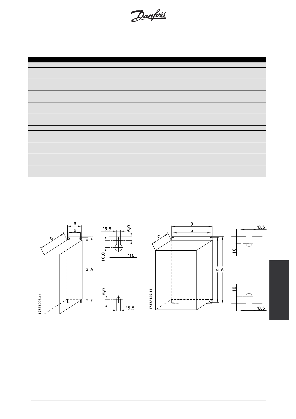
■Mechanical dimensions
All the below listed measurements are in mm.
Compact IP 20
5001 - 5003 200 - 240 V
5001 - 5005 380 - 500 V
5004 - 5006 200 - 240 V
5006 - 5011 380 - 500 V
5008 200 - 240 V
5016 - 5022 380 - 500 V
5011 - 5016 200 - 240 V
5027 - 5032 380 - 500 V
5022 - 5027 200 - 240 V
5042 - 5062 380 - 500 V
Compact IP 54
5001 - 5003 200 - 240 V
5001 - 5005 380 - 500 V
5004 - 5006 200 - 240 V
5006 - 5011 380 - 500 V
5008 - 5011 200 - 240 V
5016 - 5027 380 - 500 V
5016 - 5027 200 - 240 V
5032 - 5062 380 - 500 V
AKD 5000
ABCDabab/beType
395 220 160 384 200 100 C
395 220 200 384 200 100 C
560 242 260 540 200 200 D
700 242 260 680 200 200 D
800 308 296 780 270 200 D
460 282 195 85 260 258 100 F
530 282 195 85 330 258 100 F
810 350 280 70 560 326 200 F
940 400 280 70 690 375 200 F
ab: Minimum space above enclosure
be: Minimum space below enclosure
1: Only above enclosure (ab) IP 00 when built in a Rittal cabinet.
■Mechanical dimensions, cont.
Type C, IP20 Type D, IP20
data
Technical
MG.50.R3.02 -
23
Page 25

Typ e F, I P54
AKD 5000
24
MG.50.R3.02 -
Page 26

■Mechanical installation
AKD 5000
Please pay attention to the requirements
that apply to integration and field mounting
kit, see the below list. The information given
in the list must be observed to avoid serious damage
or injury, especially when installing large units.
The frequency converter must be installed vertically.
The frequency converter is cooled by means of air
circulation. For the unit to be able to release its cooling
air, the minimum distance over and below the unit
must be as shown in the illustration below.
To protect the unit from overheating, it must be
ensured that the ambient temperature does not rise
above the max. temperature stated for the frequency
converter and that the 24-hour average temperature is
not exceeded . The max. temperature and 24-hour
average can be seen from the General Technical Data.
If the ambient temperature is in the range of 45°C-55°
C, derating of the frequency converter will become
relevant, see Derating for ambient temperature.
The service life of the frequency converter will
be reduced if derating for ambient temperature
is not taken into account.
■Enclosure type
IP 20/Nema 1 IP 54
Compact OK OK
■Field mounting
IP 20 IP 54
Compact No OK
Compact w/IP 4x top cover
AKD 5001-5006 200 V OK OK
AKD 5001-5011 500 V OK OK
AKD 5001-5011 575 V OK -
Compact w/IP 20 terminal
cover
AKD 5008-5027 200 V OK OK
AKD 5016-5052 500 V OK OK
AKD 5016-5062 575 V OK -
MG.50.R3.02 -
Installation
25
Page 27
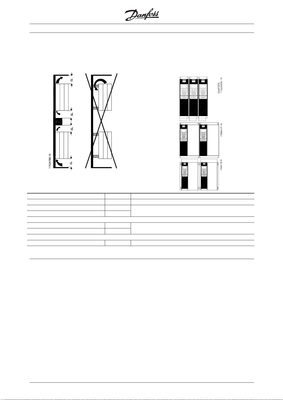
■Installation of AKD 5001-5062
All frequency converters must be installed in a
way that ensures proper cooling.
Cooling
AKD 5000
Side by side/flange by flange
All frequency converters can be mounted side
by side/flange by flange.
All units require a minimum space above and
below the enclosure.
d[mm] Comments
Compact (all enclosure types)
AKD 5001-5006, 200-240 V 100
AKD 5001-5011, 380-500 V 100
AKD 5008-5027, 200-240 V 200
AKD 5016-5062, 380-500 V 200
Installation on a plane, vertical surface (no spacers)
Installation on a plane, vertical surface (no spacers)
AKD 5032-5052, 200-240 V 225 Installation on a plane, vertical surface (no spacers)
26
MG.50.R3.02 -
Page 28
AKD 5000
■Electrical installation
The voltage on the frequency converter is
dangerous when the unit is connected to
mains. Incorrect installation of the motor or
the frequency converter may lead to material damage
or serious injury or it may be fatal. Consequently, the
instructions in this manual as well as national and local
rules and safety regulations must be complied with.
Touching the electrical parts may be fatal, even after
the mains supply has been disconnected.
Using AKD 5001-5006, 200-240 V and 380-500
V: wait at least 4 minutes.
Using AKD 5008-5052, 200-240 V: wait
at least 15 minutes.
Using AKD 5008-5500, 380-500 V: wait
at least 15 minutes.
NB!:
It is the user’s or certified electrician’s
responsibility to ensure correct earthing and
protection in accordance with applicable
national and local norms and standards.
■Electrical installation, power cables
Compact IP 20
AKD 5001-5006, 200-240 V
AKD 5001-5011, 380-500 V
AKD 5001-5011, 550-600
MG.50.R3.02 -
V
Installation
27
Page 29
AKD 5000
Compact IP 54
AKD 5001-5006, 200-240 V
AKD 5001-5011, 380-500 V
28
MG.50.R3.02 -
Page 30

AKD 5000
Compact IP 20 / IP 54
AKD 5001-5006 200-240 V
AKD 5001-5011 380-500 V
Compact IP 20
AKD 5008-5027 200-240 V
AKD 5016-5062 380-500 V
MG.50.R3.02 -
Installation
29
Page 31

Compact IP 20
AKD 5008-5027 200-240 V
AKD 5016-5062 380-500 V
AKD 5000
Compact IP 54
AKD 5008-5027 200-240 V
AKD 5016-5062 380-500 V
Compact IP 54
AKD 5008-5027 200-240 V
AKD 5016-5062 380-500 V
30
MG.50.R3.02 -
Page 32

AKD 5000
■Electrical installation - EMC precautions
The following is a guideline to good engineering
practice, when installing drives. Following these
guidelines is advised, where compliance with EN
50081, EN 55011 or EN 61800-3 First environment is
required. If the installation is in EN 61800-3 Second
environment, then it is acceptable to deviate from these
guidelines. It is however not recommended. See also
CE labelling, Emission and EMC test results under
special conditions in the Design Guide for further details.
ood engineering practice to ensure EMC-correct
G
electrical installation:
• Use only braided screened/armoured motor cables
and braided screened/armoured control cables. The
screen should provide a minimum coverage of 80%.
The screen material must be metal, not limited to
but typically copper, aluminium, steel or lead. There
are no special requirements for the mains cable.
• Installations using rigid metal conduits are not
required to use screened cable, but the motor
cable must be installed in conduit separate from
the control and mains cables. Full connection
of the conduit from the drive to the motor is
required. The EMC performance of flexible
conduits varies a lot and information from the
manufacturer must be obtained.
• Connect the screen/armour/conduit to earth
at both ends for motor cables as well as for
control cables. See also Earthing of brai
screened/armoured control cables.
• Avoid terminating the screen/armour with
twisted ends (pigtails). Such a termina
increases the high frequency impedance of the
screen, which reduces its effectiveness at high
frequencies. Use low impedance cable
or EMC cable glands instead.
• It is important to ensure good electrical contact
between the mounting plate on which t
converter is installed and the metal chassis of
the frequency converter. This however does
notapplytoIP54unitsasth
wall mounting and AKD 5032-5052, 200-240
VAC in IP20/Nema1 enclosure.
• Use starwashers and galvan
installation plates to secure good electrical
connections for IP00 and IP20 installations.
• Avoid using unscreened/u
control cables inside cabinets housing the drive(s),
whenever this can be avoided.
• An uninterrupted high fr
between the frequency converter and the motor
units is required for IP54 units.
ey are designed for
ically conductive
narmoured motor or
equency connection
ded
tion
clamps
he frequency
The illustration shows an example of an EMC-correct
electrical installation of an IP 20 frequency converter;
the frequency converter has been fitted in an installation
cabinet with an output contactor and connected
to a PLC, which in this example is installed in a
separate cabinet. In AKD 5032-5052, 200-240
VAC in Nema 1/IP20 enclosure screened cables
are connected by using EMC conduits to ensure
proper EMC performance. See illustration. Other
ways of making the installation may have as good
an EMC performance, provided the above guide
lines to engineering practice are followed.
Please note, that when the installation is not carried
through according to the guideline as well as when
unscreened cables and control wires are used, some
emission requirements are not complied with, although
the immunity requirements are fulfilled. See the section
EMC test results in the Design Guide for further details.
Installation
MG.50.R3.02 -
31
Page 33

AKD 5000
32
MG.50.R3.02 -
Page 34

■Electrical installation, selection of EMC-
correct cables
Braided screened/armoured cables are recommended
to optimise EMC immunity of the control cables and
the EMC emission from the motor cables.
The ability of a cable to reduce the in- and outgoing
radiation of electric noise depends on the transfer
impedance (Z
). The screen of a cable is normally
T
designed to reduce the transfer of electric noise;
however, a screen with a lower transfer impedance
) value is more effective than a screen with a
(Z
T
higher transfer impedance (Z
).
T
AKD 5000
Transfer impedance (Z
basis of the following factors:
- The conductibility of the screen material.
- The contact resistance between the individual
screen conductors.
- The screen coverage, i.e. the physical area
of the cable covered by the screen - often
stated as a percentage value.
- Screen type, i.e. braided or twisted pattern.
Aluminium-clad with copper wire.
Twisted copper wire or armoured steel wire cable.
Single-layer braided copper wire with varying
percentage screen coverage.
This is the typical Danfoss reference cable.
Double-layer braided copper wire.
Twin layer of braided copper wire with a magnetic,
screened/armoured intermediate layer.
) can be assessed on the
T
Transfer impedance (ZT) is rarely stated by
cable manufacturers, but it is often possible to
estimate transfer impedance (Z
) by assessing
T
the physical design of the cable.
Cable that runs in copper tube or steel tube.
Lead cable with 1.1 mm wall thickness.
MG.50.R3.02 -
Installation
33
Page 35
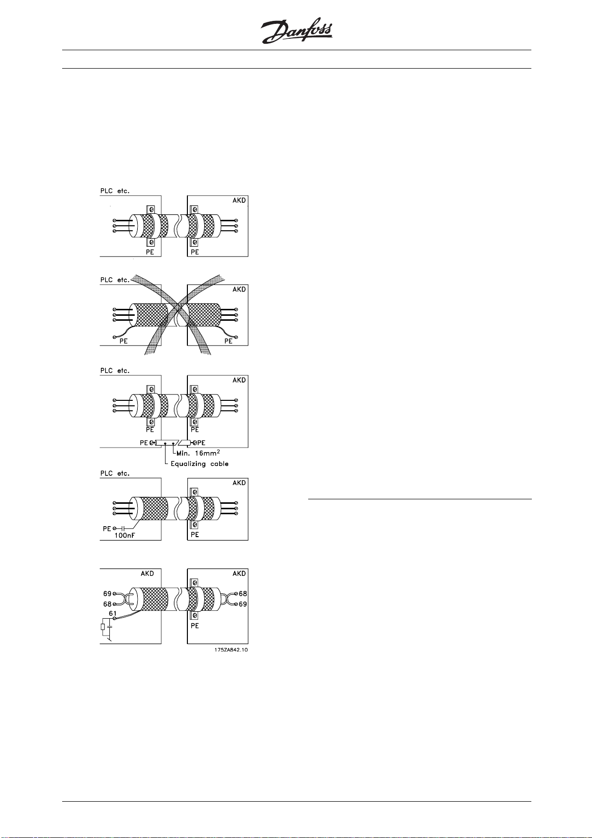
■Electrical installation - earthing of control cables
Generally speaking, control cables must be braided
screened/armoured and the screen must be
connected by means of a cable clamp at both
ends to the metal cabinet of the unit.
AKD 5000
Correct earthing
Control cables and cables for serial communication
must be fitted with cable clamps at both ends to
ensure the best possible electrical contact
The drawing below indicates how correct earthing is
carried out and what to be done if in doubt.
Wrong earthing
Do not use twisted cable ends (pigtails), since these
increase the screen impedance at high frequencies.
Protection with respect to earth potential between
PLC and frequency converter
If the earth potential between the frequency converter
and the PLC (etc.) is different, electric noise may
occur that will disturb the whole system. This
problem can be solved by fitting an equalising cable,
to be placed next to the control cable. Minimum
cable cross-section: 16 mm2.
For 50/60 Hz earth loops
If very long control cables are used, 50/60 Hz earth
loops may occur. This problem can be solved by
connecting one end of the screen to earth via a
100nF capacitor (keeping leads short).
Cables for serial communication
Low-frequency noise currents between two frequency
converters can be eliminated by connecting one end of
the screen to terminal 61. This terminal is connected
to earth via an internal RC link. It is recommended
to use twisted-pair cables to reduce the differential
mode interference between the conductors.
34
MG.50.R3.02 -
Page 36

AKD 5000
■Tightening-up torques and screw sizes
■Safety earthing
The table shows the torque required when fitting
terminals to the frequency converter. For AKD
5001-5027 200-240 V, AKD 5001-5062 380-500 V
the cables must be fastened with screws.
These figures apply to the following terminals:
(see section Electrical installation, power cables),
MMMMaaaaiiiinnnnsssstttteeeerrrrmmmmiiiinnnnaaaallllssss Nos 91, 92, 93
L1, L2, L3
MMMMoooottttoooorrrrtttteeeerrrrmmmmiiiinnnnaaaallllssss Nos 96, 97, 98
U, V, W
which enables reinforced earthing.
Apply national safety regulations.
■Motor thermal protection
EEEEaaaarrrrtttthhhhtttteeeerrrrmmmmiiiinnnnaaaallll No 94, 95, 99
BBBBrrrraaaakkkkeeeerrrreeeessssiiiissssttttoooorrrrtttteeeerrrrmmmmiiiinnnnaaaallllssss81,82
The electronic thermal relay in UL-approved frequency
converters has received the UL-approval for single
motor protection when parameter 128 has been set for
LLLLooooaaaaddddsssshhhhaaaarrrriiiinnnngggg88,89
ETR Trip and parameter 105 has been programmed to
the rated motor current (see motor nameplate).
AKD type
3x200-240V
AKD 5001-5006 0.5 - 0.6 Nm M3
AKD 5008-5011 1.8 Nm M4
AKD 5016-5022 3.0 Nm M5
AKD 5027 4.0 Nm M6
Tightening-up
torque
Screw
size
■Extra protection (RCD)
ELCB relays, multiple protective earthing or earthing
can be used as extra protection, provided that local
safety regulations are complied with.
AKD type
3x380-500V
AKD 5001-5011 0.5 - 0.6 Nm M3
AKD 5016-5027 1.8 Nm M4
AKD 5032-5042 3.0 Nm M5
AKD 5052-5062 4.0 Nm M6
Tightening-up
torque
Screw
Bolt size
In the case of an earth fault, a DC content may
develop in the faulty current.
If ELCB relays are used, local regulations must be
observed. Relays must be suitable for protection
of 3-phase equipment with a bridge rectifier and
for a brief discharge on power-up.
■Electrical installation - mains supply
See also the section Special Conditions in
Connect the three mains phases to terminals L
1,L2,L3
.
the Design Guide.
NB!:
The frequency converter has a high leakage
current and must be earthed appropriately
for safety reasons. Use earth terminal
■High voltage test
A high voltage test can be carried out by shortcircuitingterminalsU,V,W,L
1,L2
and L3and
energizing by max. 2.15 kV DC for one second
between this short-circuit and the chassis.
NB!:
The RFI switch must be closed (position
ON) when high voltage tests are carried
out (see section RFI Switch).
The mains and motor connection must be interrupted
in the case of high voltage tests of the total installation
if the leakage currents are too high.
MG.50.R3.02 -
■RFI switch
ains supply isolated from earth:
M
If the frequency converter is supplied from an isolated
mains source ( IT mains), the RFI switch can be
turned off (OFF). In OFF position, the internal RFI
capacities (filter capacitors) between the chassis and
the intermediate circuit are cut off to avoid damage
to the intermediate circuit and to reduce the earth
capacity currents (according to IEC 61800-3).
NB!:
The RFI switch is not to be operated
mains connected to the unit. Check that
the mains supply has been disconnected
before operating the RFI switch
.
NB!:
Open RFI switch is only allowed at factory
set switching frequencies.
with
Installation
35
Page 37

NB!:
The RFI switch disconnects the capacitors
galvanically to ground.
The red switches are operated by means of e.g. a
screwdriver. They are set in the OFF position when
they are pulled out and in ON position when they are
pushed in (see drawing below). Factory setting is ON.
Mains supply connected to earth:
The RFI switch must be in ON position in order for the
frequency converter to comply with the EMC-standard.
osition of RFI switches
P
AKD 5000
Compact IP 20/NEMA 1
AKD 5008 200 - 240 V
AKD 5016 - 5022 380 - 500 V
Compact IP 20/NEMA 1
AKD 5001 - 5006 200 - 240 V
AKD 5001 - 5011 380 - 500 V
Compact IP 20/NEMA 1
AKD 5011 - 5016 200 - 240 V
AKD 5027 - 5032 380 - 500 V
36
MG.50.R3.02 -
Page 38

Compact IP 20/NEMA 1
AKD 5022 - 5027 200 - 240 V
AKD 5042 - 5062 380 - 500 V
AKD 5000
Compact IP 54
AKD 5008 - 5011 200 - 240 V
AKD 5016 - 5027 380 - 500 V
Compact IP 54
AKD 5001 - 5006 200 - 240 V
AKD 5001 - 5011 380 - 500 V
MG.50.R3.02 -
Compact IP 54
AKD 5016 - 5027 200 - 240 V
AKD 5032 - 5062 380 - 500 V
Installation
37
Page 39

AKD 5000
■Electrical installation - motor cables
NB!:
If an unscreened cable is used, some
EMC requirements are not complied with,
see the Design Guide.
If the EMC specifications regarding emission are
to be complied with, the motor cable must be
screened, unless otherwise stated for the RFI filter
in question. It is important to keep the motor cable
as short as possible so as to reduce the noise level
and leakage currents to a minimum.
The motor cable screen must be connected to the
metal cabinet of the frequency converter and to the
metal cabinet of the motor. The screen connections
are to be made with the biggest possible surface
(cable clamp). This is enabled by different installation
devices in the different frequency converters.
Installation with twisted screen ends (pigtails) is
to be avoided, since these spoil the screening
effect at higher frequencies.
If it is necessary to break the screen to install a motor
isolator or motor contactor, the screen must be
continued at the lowest possible HF impedance.
The frequency converter has been tested with a given
length of cable and a given cross-section of that cable.
If the cross-section is increased, the cable capacitance
- and thus the leakage current - increases, and the
cable length must be reduced correspondingly.
■Direction of motor rotation
The factory setting is for clockwise rotation with the
frequency transformer output connected as follows.
Terminal 96 connected to U-phase
Terminal 97 connected to V-phase
Terminal 98 connected to W-phase
The direction of motor rotation can be changed by
switching two phases in the motor cable.
■Parallel coupling of motors
■Connection of motor
All types of 3-phased asynchronous standard motors
can be used with the AKD 5000 Series.
Normally, small motors are star-connected
(200/400 V,
/Y).
Large motors are delta-connected (400/690 V,
/Y).
Frequency converters are able to control several
motors connected in parallel. If the motors are to
have different rpm values, the motors must have
different rated rpm values. Motor rpm is changed
simultaneously, which means that the ratio between
the rated rpm values is maintained across the range.
The total current consumption of the motors is
not to exceed the maximum rated output current
I
for the frequency converter.
N
Problems may arise at the start and at low rpm values if
the motor sizes are widely different. This is because the
relatively high ohmic resistance in small motors calls for
a higher voltage at the start and at low rpm values.
38
MG.50.R3.02 -
Page 40

In systems with motors connected in parallel, the
electronic thermal relay (ETR) of the frequency
converter cannot be used as motor protection
for the individual motor. Consequently, additional
motor protection is required, such as thermistors
in each motor (or individual thermal relays) suitable
for frequency converter use.
Please note that the individual motor cable for each
motor must be summed and is not to exceed the
total motor cable length permitted.
■Electrical installation - brake cable
(Only standard with brake and extended with
brake. Typecode: SB, EB).
No. Function
88881111,,,,88882222 Brake resistor terminals
AKD 5000
The connection cable to the brake resistor must be
screened. Connect the screen by means of cable
clamps to the conductive back plate at the frequency
converter and to the metal cabinet of the brake resistor.
Size the brake cable cross-section to match
the brake torque. See also Brake instructions,
MI.90.FX.YY and MI.50.SX.YY for further information
regarding safe installation.
NB!:
Please note that voltages up to 960 V DC,
depending on the supply voltage, may
occur on the terminals.
■Electrical installation - relay outputs
Torque: 0.5 - 0.6 Nm
Screw size: M3
No. Function
1111----3333 Relay output, 1+3 break, 1+2 make
See parameter 323 of the Operating
Instructions. See also General
technical data.
4444,,,,5555 Relay output, 4+5 make See
parameter 326 of the Operating
Instructions.
See also General technical data.
MG.50.R3.02 -
Installation
39
Page 41

■Electrical installation - external fan supply
Torque 0,5-0,6 Nm
Screwsize: M3
Only for IP54 units in the powerrange AKD 5016-5062,
380-500 V and AKD 5008-5027, 200-240 V AC. If
the drive is supplied by the DC bus (loadsharing), the
internal fans are not supplied with AC power. In this
case they must be supplied with an external AC supply.
AKD 5000
■DIP Switches 1-4
The dipswitch is located on the control card.
It is used for serial communication, terminals 68 and 69.
The switching position shown is the factory setting.
Switch 1 has no function.
Switches 2 and 3 are used for terminating an RS
485 interface, serial communication.
Switch 4 is used for separating the common potential
for the internal 24 V DC supply from the common
potential of the external 24 V DC supply.
NB!:
Please note that when Switch 4 is in position
"OFF", the external 24 VDC supply is galvanically
isolated from the frequency converter.
■Electrical installation - bus connection
The serial bus connection in accordance with the RS
485 (2-conductor) norm is connected to terminals
68/69 of the frequency converter (signals P and N).
Signal P is the positive potential (TX+,RX+), while
signal N is the negative potential (TX-,RX-).
If more than one frequency converter is to be connected
to a given master, use parallel connections.
In order to avoid potential equalizing currents in the
screen, the cable screen can be earthed via terminal
61, which is connected to the frame via an RC-link.
■Electrical installation - control cables
All terminals for the control cables are located under
the protective cover of the frequency converter. The
protective cover (see drawing) can be removed by
means of a pointed object - a screwdriver or similar.
us termination
B
The bus must be terminated by a resistor network
at both ends. For this purpose,
and 3 on the control card for "ON".
40
set switches 2
Once the protective cover has been removed, the
actual EMC-correct installat
in the section, EMC correct installation.
ion can start. See drawings
MG.50.R3.02 -
Page 42

Tightening-up torque: 0.5-0.6 Nm
Screw size: M3
See section earthing of braided screened/armoured
control cables.
AKD 5000
No. Function
11112222,,,,11113333 Voltage supply to digital inputs
For the 24 V DC to be usable
for the digital inputs, switch 4 on
the control card must be closed.
position "ON".
11116666----33333333 Digital inputs/encoder inputs
22220000 Ground for digital inputs
33339999 Ground for analogue/digital
outputs
44442222,,,,44445555 Analogue/digital outputs for
indicating frequency, reference,
current and torque
55550000 Supply voltage to potentiometer
and thermistor 10 V DC
55553333,,,,55554444 Analogue reference input, voltage
0-±10V
55555555 Ground for analogue reference
inputs
66660000 Analogue reference input, current
0/4-20 mA
66661111 Termination for serial
communication. See section
Bus connection. This terminal is
normally not to be used.
66668888,,,,66669999 RS 485 interface, serial
communication. Where the
frequency converter is connected
to a bus, switches 2 and 3
(switches 1- 4) must be closed
on the first and the last frequency
converter. On the remaining
frequency converters, switches 2
and 3 must be open. The factory
setting is closed (position "ON").
MG.50.R3.02 -
Installation
41
Page 43

■Electrical installation
AKD 5000
Conversion of analogue inputs
Current input signal to voltage input
0-20 mA⇒0-10 V
4-20 mA⇒2-10 V
Connect 510 ohms resistor between input terminal
53 and 55 (terminal 54 and 55) and adjust minimum
and maximum values in parameters 309 and 310
(parameters 312 and 313).
42
MG.50.R3.02 -
Page 44

■Control panel (LCP)
The front of the frequency converter features a
control panel - LCP (Local Control Panel), which
makes up a complete interface for operation and
monitoring of the AKD 5000 Series.
The control panel is detachable and can - as an
alternative - be installed up to 3 metres away from
the frequency converter, e.g. on a front panel,
by means of a mounting kit option.
The functions of the control panel can be
divided into three groups:
• display
• keys for changing program parameters
• keys for local operation
All data are indicated by means of a 4-line
alpha-numeric display, which in normal operation
is able to show 4 measurements and 3 operating
conditions continuously. During programming, all the
information required for quick, effective parameter
Setup of the frequency converter will be displayed. As
a supplement to the display, there are three LEDs for
voltage (power or 24 V external), warning and alarm.
All program parameters of the frequency converter can
be changed immediately from the control panel, unless
this function has been blocked via parameter 018.
AKD 5000
AKD
Operation of the
■Control panel - display
The LCD-display has rear lighting and a total of 4
alpha-numeric lines together with a box that shows
the direction of rotation (arrow) and the chosen
Setup as well as the Setup in which programming
is taking place if that is the case.
1st line
2nd line
3rd line
4th line
1st line shows up to 3 measurements continuously
in normal operating status or a text which
explains the 2 nd line.
2nd line shows a measurement with related
unit continuously, regardless of status (except
inthecaseofalarm/warning).
12345678901234567890
SETUP
12345678
1
12345678901234567890
12345678901234567890
3rd line is normally blank and is used in the menu
mode to show the selected parameter number or
parameter group number and name.
4th line is used in operating status for showing a
status text or in data change mode for showing the
175ZA443.10
mode or value of the selected parameter.
An arrow indicates the direction of rotation of the
motor. Furthermore, the Setup which has been
selected as the Active Setup in parameter 004 is
shown. When programming another Setup than
the Active Setup, the number of the Setup which
is being programmed will appear to the right. This
second Setup number will flash.
■Control panel - LEDs
At thebottom of the control panel is a red alarm LED and
a yellow warning LED, as well as a green voltage LED.
MG.50.R3.02 -
43
Page 45

If certain threshold values are exceeded, the alarm
and/or warning LED lights up together with a status
and alarm text on the control panel.
The voltage LED is activated when the frequency
converter receives voltage, or 24 V external supply; at
the same time the rear lighting of the display will be on.
■Control panel - control keys
The control keys are divided into functions. This means
that the keys between display and indicator lamps
are used for parameter Setup, including choice of
display indication during normal operation.
AKD 5000
[OK] is used for confirming a change of the
parameter selected.
[+/-] is used for selecting parameter and
for changing the chosen parameter or for
changing the read out in line 2.
[<>] is used for selecting group and to
move the cursor when changing numerical
parameters.
[STOP / RESET] is used for stopping
the motor connected or for resetting the
frequency converter after a drop-out (trip).
Can be selected via parameter 014 to be
active or inactive. If stop is activated, line 2
will flash, and [START] must be activated.
[JOG] overrides the output frequency to
a preset frequency while the key is kept
down. Can be selected via parameter 015
to be active or inactive.
Keys for local control are found under the
indicator LEDs.
■Control key functions
[DISPLAY / STATUS] is used for selecting
the mode of display or for changing back
to Display mode from either the Quick
menu mode or the Menu mode.
[QUICK MENU] is used for programming
the parameters that belong under the
Quick menu mode. It is possible to switch
directly between Quick menu mode and
Menu mode.
[MENU] is used for programming all
parameters. It is possible to switch directly
betweenMenumodeandQuickmenu
mode.
[CHANGE DATA ] is used for changing
the parameter selected either in the Menu
mode or the Quick menu mode.
[CANCEL] is used if a change of the
selected parameter is not to be carried out.
[FWD / REV] changes the direction of
rotation of the motor, which is indicated
by means of the arrow on the display
although only in Local. Can be selected via
parameter 016 to be active or inactive.
[START] is used for starting the frequency
converter after stop via the "Stop" key. Is
always active, but cannot override a stop
command given via the terminal strip.
NB!:
If the keys for local control have been
selected as active, they will remain active
both when the frequency has been set for
Local Control and for Remote Control via parameter
002, although with the exception of [Fwd/rev],
which is only active in Local operation.
NB!:
If no external stop function has been selected
and the [Stop] key has been selected as
inactive, the motor can be started and can only
be stopped by disconnecting the voltage to the motor.
■Control panel - display read-outs
The display read-out state can be varied - see the list
below - depending on whether the frequency converter
is in normal operation or is being programmed.
44
MG.50.R3.02 -
Page 46

AKD 5000
■Display mode
In normal operation, up to 4 different operating
variables can be indicated continuously: 1.1 and 1.2
and 1.3 and 2, and in line 4 the present operating
status or alarms and warnings that have arisen.
VAR 1.1 VAR 1.2 VAR 1.3
VAR 2
SETUP
1
STATUS
■Display mode - selection of read-outstate
There are three options in connection with the
choice of read-out state in the Display mode - I, II
and III. The choice of read-out state determines the
number of operating variables read out.
Read-out state: I: II: III:
Line 1 Description
for operating
variable in line 2
Data value for
3operating
variables in line
1
Description for
3operating
variables in line
1
The table below gives the units linked to the variables
in the first and second line of the display.
OOOOppppeeeerrrraaaattttiiiinnnnggggvvvvaaaarrrriiiiaaaabbbblllleeee::::U
Reference [%]
Reference [unit]
Feedback [unit]
Frequency [Hz]
Frequency x scaling [-]
Motor current [A]
To rq ue [ %]
Power [kW]
Power [HP]
Output energy [kWh]
Motor voltage [V]
DC-link voltage [V]
Motor thermal load [%]
AKD thermal load [%]
Hours run [Hours]
Input status, dig. Input [Binary code]
Input status, analogue terminal 53 [V]
Input status, analogue terminal 54 [V]
Input status, analogue terminal 60 [mA]
Pulse reference [Hz]
External reference [%]
Status word [Hex]
Brake effect/2 min. [kW]
Brake effect/sec. [kW]
Heat sink temp. [ºC]
Alarm word [Hex]
Control word [Hex]
Warning word 1 [Hex]
Extended status word [Hex]
Communication option card warning [Hex]
RPM [min
RPM x scaling [ - ]
UUUnnnniiiitttt:::
:
-1
]
AKD
Operation of the
Operating variables 1.1 and 1.2 and 1.3 in the first
line, and operating variable 2 in the second line are
selected via parameter 009, 010, 011 and 012.
• Read-out state I:
This read-out state is standard after starting
up or after initialisation.
FREQUENCY
50.0 Hz
MOTOR IS RUNNING
Line 2 gives the data value of an operating variable with
related unit, and line 1 provides a text which explains
line 2, cf. table. In the example, Frequency has
been selected as variable via parameter 009. During
normal operation another variable can immediately
be read out by using the [+/-] keys.
• Read-out state II:
Switching between read-out states I an
by pressing the [DISPLAY / STATUS] key.
d II is effected
MG.50.R3.02 -
45
Page 47

24.3% 30.2% 13.8A
50.0 Hz
MOTOR IS RUNNING
In this state, data values for four operating values
are shown at the same time, giving the related
unit, cf. table. In the example, Reference, Torque,
Current and Frequency are selected as variables
in the first and second line.
• Read-out state III:
This read-out state can be held as long as the
[DISPLAY/STATUS] key is pressed. When the
key is released, the system switches back to
Read-out state II, unless the key is pressed for
less that approx. 1 sec., in which case the system
always reverts to Read-out state I.
REF% TORQUE CURR A
50.0 Hz
MOTOR IS RUNNING
This is where parameter names and units for operating
variables in the first and second line are given operating variable 2 remains unchanged.
SETUP
1
AKD 5000
achoicebetweentwoprogrammingmodes-a
Menu mode and a Quick menu mode.
The former provides access to all parameters. The
latter takes the user through a few parameters
which make it possible in most cases to start
operating the frequency converter.
Regardless of the mode of programming, a change
of a parameter will take effect and be visible both in
theMenumodeandintheQuickmenumode.
■Structure for the Quick menu mode versus
the Menu mode
In addition to having a name, each parameter is linked
up with a number which is the same regardless of
the programming mode. In the Menu mode, the
parameters are divided into groups, with the first digit
of the parameter number (from the left) indicating the
group number of the parameter in question.
• The quick menu takes the user through a number
of parameters that may be enough to get the
motor to run nearly optimally, if the factory setting
for the other parameters takes the desired control
functions into account, as well as the configuration
of signal inputs/outputs (control terminals).
• The Menu mode makes it possible to select
and change all parameters at the user’soption.
However, some parameters will be "missing",
depending on the choice of configuration (parameter
100), e.g. open loop hides all the P.I.D. parameters.
• Display state IV:
This display state can be produced during operation
if another setup is to be changed without stopping
the frequency converter. This function is activated
in parameter 005, Programming Setup.
24.3% 30.2% 13.8A
50.0 Hz
MOTOR IS RUNNING
The selected progra
to the right of the active setup.
■Parameter Setup
The AKD 5000 Series can be used for practically
all assignments
parameters is quite large. Also, this series offers
mming setup number will flash
, which is why the number of
■Quick Setup
The Quick Setup starts with pressing the [QUICK
MENU] key, which brings out the following
read-out on the display:
QUICK MENU 1 OF 13
50.0 HZ
001 LANGUAGE
ENGLISH
At the bottom of the display, the parameter number
and name are given together with the status/value
of the first parameter under Quick Setup. The first
time the [Quick Menu] key is pressed after the
unit has been switched on, the read-outs always
start at pos. 1 - see table below.
46
MG.50.R3.02 -
Page 48

AKD 5000
■Parameter selection
The selection of parameter is effected by means of the
[+/-] keys. The following parameters are accessible:
PPPPoooossss....::::N
1 001 Language
2 102 Motor output [kW]]
3 103 Motor voltage [V]
4 104 Motor frequency [Hz]
5 105 Motor current [A]
6 106 Rated motor speed [rpm]
7 107 Automatic motor adaptation,
8 204 Minimum reference [Hz]
9 205 Maximum reference [Hz]
10 207 Ramp-up time 1 [sec.]
11 208 Ramp-down time 1 [sec.]
12 002 Local/remote control
13 003 Local reference
■Menu mode
The Menu mode is started by pressing the [MENU] key,
which produces the following read-out on the display:
:P
NNNoooo....:::
PPPaaaarrrraaaammmmeeeetttteeeerrrr:::
AMA
:U
FREQUENCY
UUUnnnniiiitttt:::
GGGGrrrroooouuuuppppnnnnoooo....P
0Operation&Display
1Load&Motor
:
2 References & Limits
3 Inputs & Outputs
4 Special functions
5 Serial communication
6 Technical functions
7 Application Options
8 Fieldbus Profile
9 Fieldbus Communication
PPPaaaarrrraaaammmmeeeetttteeeerrrrggggrrrroooouuuupppp:::
:
AKD
Operation of the
When the desired parameter group has been
selected, each parameter can be chosen by
means of the [+/-] keys:
FREQUENCY
50.0 Hz
001 LANGUAGE
ENGLISH
The 3rd line of the display shows the parameter
number and name, while the status/value of the
selected parameter are shown in line 4.
50.0 Hz
0 KEYB.&DISPLAY
Line 3 on the display shows the parameter
group number and name.
■Parameter selection
IntheMenumodetheparametersaredivided
into groups. Selection of parameter group is
effected by means of the [<>] keys.
The following parameter groups are accessible:
■Changing data
Regardless of whether a parameter has been selected
under the Quick menu or the Menu mode, the
procedure for changing data is the same.
Pressing the [CHANGE DATA] key gives access to
changing the selected parameter, following which the
underlining in line 4 will flash on the display.
The procedure for changing data depends on
whether the selected parameter represents a
numerical data value or a text value.
■Changing a text value
If the selected parameter is a text value, the text value
is changed by means of the [+/-] keys.
FREQUENCY
50.0 Hz
001 LANGUAGE
ENGLISH
MG.50.R3.02 -
47
Page 49

AKD 5000
The bottom display line shows the text value that will be
entered (saved) when acknowledgement is given [OK].
■Change of group of numeric data values
If the chosen parameter represents a numeric
data value, the chosen data value is changed
by means of the [+/-] keys.
FREQUENCY
SETUP
50.0 HZ
102 MOTOR POWER
0.37 KW
FREQUENCY
50.0 HZ
102 MOTOR POWER
0.55 KW
The chosen data value is indicated by the digit flashing.
The bottom display line shows the data value that will
be entered (saved) when signing off with [OK].
1
SETUP
1
SETUP
1
■Changing of data value, step-by-step
Certain parameters can be changed step by step
or infinitely variably. This applies to Motor power
(parameter 102), Motor voltage (parameter 103)
and Motor frequency (parameter 104).
The parameters are changed both as agroup of numeric
data values andas numeric data values infinitely variably.
■Read out and programming of indexed parameters
Parameters are indexed when placed in a rolling stack.
Parameter 615 - 617 contain a historical log which
can be read out. Choose the actual parameter, press
the [CHANGE DATA] key and use the [+] and [-]
keys to scroll through the log of values. During the
read out line 4 of the display will flash.
If a bus option is mounted in the drive, the
programming of parameter 915 - 916 needs to be
carried through in the following way:
Choose the actual parameter, press the [CHANGE
DATA] key and use the [+] and [-] keys to scroll through
the different indexed values. To change the value of
the parameter, select the indexed value and press the
[CHANGE DATA] key. Using the [+] and [-] keys the
value to be changed will flash. To accept the new
setting, press [OK], to abort, press [CANCEL].
■Infinitely variable change of numericdata value
If the chosen parameter represents a numeric data
value, a digit is first selected by means of the [<>] keys.
FREQUENCY
50.0 Hz
130 START FREQUENCY
09.0 HZ
Then the chosen digit is changed infinitely variably
by means of the [+/-] keys:
FREQUENCY
50.0 Hz
130 START FREQUENCY
10.0 HZ
The chosen digit is indicated by the digit flashing. The
bottom display line shows the data value that will be
entered (saved) when signing off with [OK].
SETUP
1
SETUP
1
■Initialisation to factory setting
The frequency converter can be initialised to
factory settings in two ways.
nitialisation by parameter 620
I
- Recommended initialisation
• Select parameter 620
• Press [CHANGE]
• Select "Initialisation"
• Press the [OK] key
• Cut off the mains supply and wait until
the display turns off.
• Reconnect the mains supply - the frequency
converter is now reset.
This parameter initialises all except:
500 Serial communication address
501 Baud rate for serial communication
601-605 Operating data
615-617 Fault logs
Manual initialisation
• Disconnect from mains and wait until the
display turns off.
48
MG.50.R3.02 -
Page 50

• Press the following keys at the same time:
[Display/status]
[Change data]
[OK]
• Reconnecting the mains supply while
pressing the keys.
• Release the keys
• The frequency converter has now been
programmed for the factory setting.
AKD 5000
This parameter initialises all except:
600-605 Operating data
NB!:
Settings for serial communication and
fault logs are reset.
AKD
Operation of the
MG.50.R3.02 -
49
Page 51

■Menu structure
DISPLAY MODE
VAR 1.1 VAR 1.2 VAR 1.3
▲
VAR 2
STATUS
AKD 5000
▲
MENU MODE
FREQUENCY
50.0 HZ
0 KEYB.&DISPLAY
Choice of
parameter
DATA MODE
FREQUENCY
50.0 HZ
001 LANGUAGE
ENGLISH
▲
QUICK MENU 1 OF 13
▲
Choice of
group
▲
▲
▲
50.0 HZ
001 LANGUAGE
ENGLISH
▲
QUICK MENU MODE
50
DATA CHANGE MODE
FREQUENCY
50.0 HZ
001 LANGUAGE
ENGLISH
175ZA446.11
Choice of
data value
▲
DATA CHANGE MODE
QUICK MENU 1 OF 13
50.0 HZ
001 LANGUAGE
ENGLISH
MG.50.R3.02 -
Page 52

AKD 5000
■Application configuration
There is a choice of the following configurations:
Using this parameter enables the choice of a
configuration (setting) of the frequency converter
that fits the application in which the frequency
converter is to be active.
- Speed control, open loop
- Speed control, closed loop
- Process control, closed loop
- Torque control, open loop
NB!:
First, the motor nameplate date must be
set in parameters 102-106.
■Setting of parameters
Select Speed control, open loop if a normal
speed adjustment without external feedback
SSSSppppeeeeeeeeddddccccoooonnnnttttrrrroooollll,,,,ooooppppeeeennnnlllloooooooopppp::::
Parameter:
100 Configuration Speed control, open loop [0]
200 Output frequency range/direction
201 Output frequency low limit Only if [0] or [2] in par. 200
202 Output frequency high limit
203 Reference/feedback range
204 Minimum reference Only if [0] in par. 203
205 Maximum reference
Setting: Data value:
- Torque control, speed feedback
The selection of special motor characteristics can be
combined with any application configuration.
signals is required (the internal slip compensation
is operating) from motor or unit.
Set the following parameters in order shown:
Application
configuration
Select Process control, closed loop if the application
has a feedback signal that is not directly related to
as temperature, pressure, etc. Set the following
parameters in the order shown:
motor speed (rpm/Hz), but some other unit, such
PPPPrrrroooocccceeeessssssssccccoooonnnnttttrrrroooollll,,,,cccclllloooosssseeeeddddlllloooooooopppp((((PPPPrrrroooocccceeeessssssssPPPPIIIIDDDD))))::::
Parameter:
100 Configuration Process control, closed loop [3]
200 Output frequency range/direction
201 Output frequency low limit
202 Output frequency high limit
203 Reference/feedback range
414 Minimum feedback Only if [0] or [2] in par. 200
415 Maximum feedback
204 Minimum reference Only if [0] in par. 203
205 Maximum reference
416 Process units
437 Process PID normal/inverse
439 Process PID start frequency
440 Process PID proportional gain
441 Process PID integration time
444 Process PID lowpass filter
Setting: Data value:
MG.50.R3.02 -
51
Page 53

■Automatic Motor Adaptation, AMA
Automatic motor adaptation is a test algorithm
that measures the electrical motor parameters at
a motor standstill. This means that AMA itself
does not supply any torque.
AMA is useful when commissioning systems, where
the user wants to optimise the adjustment of the
frequency converter to the motor applied. This feature
is used in particular where the factory setting does
not adequately cover the motor in question.
There are two motor parameters that are of primary
significance in automatic motor adaptation: the
stator resistance, Rs, and the reactance at normal
magnetising level, Xs. Parameter 107 allows a choice
of automatic motor adaptation, with determination
of both Rs and Xs, or reduced automatic motor
adaptation with determination of only Rs.
The duration of a total automatic motor adaptation
varies from a few minutes on small motors to more
than 10 minutes on large motors.
Limitations and preconditions:
• For AMA to be able to determine the motor
parameters optimally, the correct nameplate data
for the motor connected to the frequency converter
must be entered in parameters 102 to 106.
• For the best adjustment of the frequency
converter, it is recommended to carry out AMA
on a cold motor. Repeated AMA runs may lead
to a heating of the motor that will result in an
increase of the stator resistance, Rs.
• AMA can only be carried out if the rated motor
current is minimum 35% of the rated output
current of the frequency converter. AMA can be
carried out up to one oversize motor.
• If a LC filter is inserted between the frequ
converter and the motor, it will only be possible
to carry out a reduced test. If an overall
setting is required, remove the LC filte
running a total AMA. After completion of the
AMA reinsert the LC filter.
• If motors are coupled in paralle
reduced AMA if any.
• When using synchronous motors it is only
possible to make a reduced AMA.
• Long motor cables can have an effect on the
implementation of theAMA function if their resistance
is bigger than the stator resis
lonlyuse
tance of the motor.
ency
rwhile
AKD 5000
How to perform an AMA
1. Press the [STOP/RESET] key
2. Set motor nameplate data in parameters 102 to 106
3. Select whether a total [ENABLE (RS,XS)]or a reduced
[ENABLE RS] AMA is required in parameter 107
4. Connect terminal 12 (24 VDC) to terminal
27 on the control card
5. Press the [START] key or connect terminal
18 (start) to terminal 12 (24 VDC) to start the
automatic motor adaptation.
Now the automatic motor adaptation goes through
four tests (for reduced AMA only the first two tests).
The different tests can be followed in the display as
dots after the text WORKING in parameter 107:
1. Initial error check where nameplate data and physical
errors are checked. Display shows WORKING.
2. DC test where the stator resistance is estimated.
Display shows WORKING..
3. Transient test where the leakage inductance is
estimated. Display shows WORKING...
4. .AC test where the stator reactance is estimated.
Display shows WORKING....
NB!:
AMA can only be carried out if there are
n
o alarms during tuning.
Discontinue AMA
If the automatic motor adaptation is to be discontinued,
press the [STOP/RESET] key or disconnect
terminal 18 from terminal 12.
The automatic motor adaptation ends up with one
of the following messages after the test:
Warnings and alarm messages
ALARM 21
Auto-optimisation OK
Press the [STOP/RESET] key or disconnect terminal 18
from terminal 12. This alarm indicates that the AMA is
OK and that the drive is correctly adapted to the motor.
ALARM 22
Auto-optimisation not OK
[AUTO MOTOR ADAPT OK]
A fault has been found during automatic motor
adaptation. Press the [STOP/RESET] key or disconnect
terminal 18 from terminal 12. Check the possible cause
to the fault related to the alarm message given. The
figure after the text is the error code, which can be
seen in the fault log in parameter 615. Automatic motor
adaptation does not update parameters. You may
choose to run a reduced automatic motor adaptation.
52
MG.50.R3.02 -
Page 54

CHECK P.103,105 [0]
[AUTO MOT ADAPT FAIL] Parameter 102,
103 or 105 has a wrong setting. Correct the
setting and start AMA all over.
LOW P.105 [1]
The motor is too small for AMA to be carried out.
If AMA is to be enabled, the rated motor current
(parameter 105) must be higher than 35% of the rated
output current of the frequency converter.
ASYMMETRICAL IMPEDANCE [2]
AMA has detected an asymmetrical impedance
in the motor connected to the system. The
motor could be defective.
MOTOR TOO BIG [3]
The motor connected to the system is too big for
AMA to be carried out. The setting in parameter
102 does not match the motor used.
MOTOR TOO SMALL [4]
The motor connected to the system is too small for
AMA to be carried out. The setting in parameter
102 does not match the motor used.
TIME OUT [5]
AMA fails because of noisy measuring signals. Try to
start AMA all over a number of times, until AMA is
carried out. Please note that repeated AMA runs may
heat the motor to a level where the stator resistance RS
is increased. In most cases, however, this is not critical.
INTERRUPTED BY USER [6]
AMA has been interrupted by the user.
INTERNAL FAULT [7]
An internal fault has occurred in the frequency
converter. Contact your Danfoss supplier.
AKD 5000
WARNING 39 - 42
A fault have been encountered during automatic
motor adaptation. Check the possible fault causes
in accordance with the warning message. Press
the [CHANGE DATA key and select "CONTINUE"
if AMA is to continue despite the warning or press
the [STOP/RESET] key or disconnect terminal 18
from terminal 12 to discontinue AMA.
WARNING: 39
CHECK P.104,106
The setting of parameter 102, 104 or 106
is probably wrong. Check the setting and
choose ‘Continue’ or ‘Stop’.
WARNING: 40
CHECK P.103,105
The setting of parameter 102, 103 or 105
is probably wrong. Check the setting and
choose ‘Continue’ or ‘Stop’.
WARNING: 41
MOTOR TOO BIG
The motor used is probably too big for AMA to
be carried out. The setting in parameter 102
may not match the motor. Check the motor
and choose ‘Continue’ or ‘Stop’.
WARNING: 42
MOTOR TOO SMAL L
The motor used is probably too small for AMA
to be carried out. The setting in parameter 102
may not match the motor. Check the motor
and choose ‘Continue’ or ‘Stop’.
Special
functions
LIMIT VALUE FAULT [8]
The parameter values found for the motor are
outside the acceptable range within which the
frequency converter is able to work.
MOTOR ROTATES [9]
The motor shaft rotates. Make sure that the
load is not able to make the motor shaft rotate.
Then start AMA all over.
MG.50.R3.02 -
53
Page 55

AKD 5000
■PID for process control
eedback
F
The feedback signal must be connected to a terminal
on the frequency converter. Use the list below to
decide which terminal is to be used and which
parameters are to be programmed.
Feedback type Terminal Parameters
Pulse 33 307
Voltage 53 308, 309, 310
Current 60 314, 315, 316
Furthermore, the minimum and maximum feedback
(parameters 414 and 415) must be set to a value in
the process unit that corresponds to the minimum
and maximum value on the terminal.
Select process unit in parameter 416.
R
eference
A minimum and a maximum reference can be set (204
and 205), which limit the sum of all references. The
reference range cannot exceed the feedback range.
If one or several setpoint references are required,
the simplest way is to set such reference directly
in parameters 215 to 218. Select between the
preset references by connecting terminals 16, 17,
29, 32 and/or 33 to terminal 12. Which terminals
that are used depends on the choice made in the
parameters of the various terminals (parameters
300, 301, 305, 306 and/or 307). Use the table
below when selecting preset references.
Preset ref. msb Preset ref. lsb
tref.1
Prese
00
(par. 215)
tref.2
Prese
01
(par. 216)
Preset
ref. 3
10
(par. 217)
Preset
ref. 4
11
(par. 218)
If an external reference is required, this can either
be an analogue or a pulse reference. If current
is used as a feedback signal, only voltage can
be used as an analogue reference. Use the
following list to decide which terminal to use and
which parameters to program.
Reference type Terminal Parameters
Pulse 17 or 29 301 or 305
Voltage 53 or 54 308, 309, 310 or
311, 312, 313
Current 60 314, 315, 316
Relative references can be programmed. A relative
referenceisapercentagevalue(Y)ofthesumof
the external references (X). This percentage value
is added to the sum of the external references,
which produces the active reference (X + XY). See
section Handling of multi references.
If relative references are to be used, parameter 214 is to
be set to Relative [1]. This makes the preset references
relative. Furthermore, Relative reference [4] can be
programmed on terminal 54 and/or 60. If an external
relative reference is selected, the signal on the input will
be a percentage value of the full range of the terminal.
The relative references are added with signs.
NB!:
Terminals that are not in use should preferably
be set to No function [0].
I
nverse control
If the drive has to react with increasing speed on
and increasing feedback, Inverse must be selected in
parameter 437. Normal control means that the motor
speed decreases when the feedback signal increases.
A
nti Windup
The process controller comes with the anti windup
function in active position. This function ensures
that when either a frequency limit or a torque limit
is reached, the integrator will be set to a gain that
corresponds to the actual frequency. This avoids
integrating on an error that cannot in any case be
compensated for by means of a speed change.
S
tart-up conditions
In some applications, optimum setting of the process
controller will mean that it takes an excessive time
for the desired process value to be reached. In
such applications it might be an advantage to fix a
motor frequency to which the frequency converter is
to bring the motor before the process controller is
activated. This is done by programming a Process
PID start frequency in parameter 439.
L
owpass filter
If there are oscillations of the current/voltage feedback
signal, these can be dampened
filter. Set a suitable lowpass filter time constant. This
time constant represents the limitfrequency of the
ripples occurring on the fe
filter has been set to 0.1s, the limit frequency will be 10
RAD/sec., corresponding to (10/2 x π) = 1.6 Hz. This
will mean that all curren
than 1.6 oscillations per second will be removed by
the filter. In other words, control will only be carried
out on a feedback si
ts/voltages that vary by more
gnal that varies by a frequency of
by means of a lowpass
edback signal. If the lowpass
54
MG.50.R3.02 -
Page 56

AKD 5000
less than 1.6 Hz. Choose a suitable time constant in
parameter 444, Process PID Lowpass filter.
ptimisation of the process controller
O
The basic settings have now been made; all that needs
to be done is to optimise the proportional gain, the
integration time and the differentiation time (parameters
440, 441, 442). In most processes, this can be done
by following the guidelines given below.
1. Start the motor
2. Set parameter 440 (proportional gain) to 0.3 and
increase it until the feedback signal again begins
to vary continuously. Then reduce the value until
the feedback signal has stabilised. Now lower
the proportional gain by 40-60%.
3. Set parameter 441 (integration time) to 20s
and reduce the value until the feedback signal
again begins to vary continuously. Increase the
integration time until the feedback signal stabilises,
followed by an increase of 15-50%.
4. Only use parameter 442 for very fast-acting
systems only (differentiation time). The typical
value is four times the set integration time. The
differentiator should only be used when the
setting of the proportional gain and the integration
time has been fully optimised.
NB!:
If necessary, start/stop can be activated
a number of times in order to provoke a
variation of the feedback signal.
See also the examples of connection given
in the Design Guide.
■Quick discharge
This function calls for a frequency converter of type EB.
This function is used for discharging the capacitors
in the intermediate circuit after the mai
ns supply
has been interrupted. This is a useful function for
servicing the frequency converter and/or the motor
installation. The motor must be
stopped before
quick discharge is activated. If the motor acts as a
generator, quick discharge is not possible.
intermediate circuit voltage has dropped to a given
value and the rectifier has stopped.
In order to obtain the possibility of a quick discharge,
the frequency converter requires an external 24 V DC
supply to terminals 35 and 36, as well as a suitable
brake resistor on terminals 81 and 82.
For sizing of the discharge resistor for quick discharge,
see Brake Instructions MI.50.DX.XX.
NB!:
Quick discharge is only possible if the
frequency converter has 24 Volts external
DC supply and if an external brake/discharge
resistor has been connected.
Before servicing the installation (frequency
converter + motor), it must be checked
that the intermediate circuit voltage
is below 60 V DC. This is done by measuring
terminals 88 and 89, load-sharing.
NB!:
The power dissipation during quick discharge
does not form part of the power monitoring
function, parameter 403. When sizing resistors,
this fact should be taken into consideration.
Parameter 408 = [1]
Quick discharge
activated
Check 24 Volts
external DC supply
24 Volts external
DC supply OK
Start
Quick discharge
Discharge
Discharge completed
175ZA447.10
No 24 Volts external
DC supply
Timeout
TRIP (RESET)
ALARM:33
Q.DISCHARGING FAILED
TRIP (RESET)
ALARM:33
Q.DISCHARGING FAILED
POWER IS DISCHARGED
Special
functions
The quick discharge function can be selected
via parameter 408. The function starts when the
■Mains failure/quick discharge with mains
failure inverse
The first column in the
table shows Mains failure ,
which is selected in parameter 407. If no function
MG.50.R3.02 -
is selected, the mains failure procedure will not be
carried out. If Controlled ramp-down [1] is selected,
the frequency conve
rter will take the motor down to 0
Hz. If Enable [1] has been selected in parameter 408,
55
Page 57

AKD 5000
a quick discharge of the intermediate circuit voltage
will be carried out after the motor has stopped.
Using a digital input, it is possible to activate mains
failureand/orquickdischarge. Thisisdoneby
selecting Mains failure inverse on one of the control
NB!:
The frequency converter can be completely
damaged if the Quick-discharge function
is repeated, using the digital input while
mains voltage is on.
terminals (16, 17, 29, 32, 33). Mains failure inverse
is active in the logical ’0’ situation.
Mains failure par.
407
No function [0] Disable [0] Logical ’0’ 1
No function [0] Disable [0] Logical ’1’ 2
No function [0] Enable [1] Logical ’0’ 3
No function [0] Enable [1] Logical ’1’ 4
[1]-[4] Disable [0] Logical ’0’ 5
[1]-[4] Disable [0] Logical ’1’ 6
[1]-[4] Enable [1] Logical ’0’ 7
[1]-[4] Enable [1] Logical ’1’ 8
Quick discharge par. 408 Mains failure inverse digital
input
Function no. 1
Mains failure and quick discharge are not active.
unction no. 2
F
Mains failure and quick discharge are not active.
F
unction no. 3
The digital input activates the quick discharge function,
regardless of the intermediate circuit voltage level and
regardless of whether the motor is running.
Function
F
unction no. 4
Quick discharge is activated when the intermediate
circuit voltage has dropped to a given value and
the inverters have stopped. See procedure
on previous page.
F
unction no. 5
The digital input activates the mains failure function,
regardless of whether the unit receives any supply
voltage. See the different functions in parameter 407.
unction no. 6
F
The mains failure function is activated when the
intermediate circuit voltage has dropped to a given
value. The selected function in case of mains
failure is selected in parameter 407.
F
unction no. 7
The digital input activates both the quick discharge and
the mains failure function, regardless of the intermediate
circuit voltage level and regardless of whether the
motor is running. First the mains failure function will be
active; subsequently there will be a quick discharge.
56
unction no. 8
F
Quick discharge and mains failure function are activated
when the intermediate circuit level drops to a given level.
First the mains failure function will be active;
subsequently there will be a quick discharge.
MG.50.R3.02 -
Page 58

AKD 5000
■Flying start
This function makes it possible to "catch" a motor
that is spinning freely and for the frequency converter
to take control of the motor speed. This function can
be enabled or disabled via parameter 445.
If flying start has been selected, there will be four
situations in which the function is activated:
1. After a coast has been given via terminal 27.
2. After power-up.
3. If the frequency converter is in a trip state and
a reset signal has been given.
4. If the frequency converter releases the motor
because of a fault state and the fault disappears
before a trip, the frequency converter will catch
the motor and go back to the reference.
1. Flying start is active.
the DC brake is active via parameters 125 and 126. If
Both directions is selected, the frequency converter will
first find out in which direction the motor rotates and
then search for the frequency. If the motor is not found,
the system assumes that the motor is at a standstill or
is rotating at a low speed, and the frequency converter
will start the motor in the normal way after searching.
3. The frequency converter trips and Flying
start is active.
2. Flying start is active.
The search sequence for the spinning motor depends
on Rotation, frequency/direction (parameter 200). If
only clockwise is select
start looking from Maximum frequency (parameter 202)
down to 0 Hz. If the frequency converter does not find
the spinning motor dur
carry out a DC braking so as to try to bring the speed
of the spinning motor down to 0 rpm. This requires that
ed, the frequency converter will
ing the search sequence, it will
4. The frequency converter momentarily
releases the motor. Flying start is activated
and catches the motor again.
■Normal/high overload torque control, open loop
This function enables the frequency converter toperform
a constant 100% torque, using an o
The choice between a normal or a high overload torque
characteristic is made in parameter 101.
This is also where to choose between a high/normal
constant torque characteristic (CT) or a high/normal
VT torque characteristic
If a high torque characteristic is chosen, a rated
motor with the frequency converter obtains up to
160% torque for 1 min. i
normal torque characteristic is chosen, an oversize
motor allows up to 110% torque performance for up
nbothCTandVT.Ifa
versize motor.
Special
functions
MG.50.R3.02 -
57
Page 59

to1min. inbothCTandVT.Thisfunctionisused
mainly for pumps and fans, since these applications
do not require an overload torque.
The advantage of choosing a normal torque
characteristic for an oversize motor is that the frequency
converter will be able constantly to yield 100% torque,
without derating as a result of a bigger motor.
NB!:
This function c
5001-5006, 200-240 Volts, and AKD
5001-5011, 380-500 Volts.
■Internal current regulator
The AKD 5000 features an integral current limit
regulator which is activated when the motor current,
and thus the torque, is higher than the torque
limits set in parameter 221 and 222.
When AKD 5000 Series is at the current limit
during motor operation or regenerative operation,
the frequency converter will try to get below the
preset torque limits as quickly as possible without
losing control of the motor.
While the current regulator is active, the frequency
converter can only be stopped by means of terminal
27 if set to Coasting stop, inverse [0] or Reset and
coasting stop, inverse [1]. A signal on terminals
16-33 will not be active until the frequency converter
has moved away from the current limit.
Please note that the motor will not use the
ramp-down time, since terminal 27 must be
programmed for Coasting stop, inverse [0] or
Reset and coasting stop, inverse [1].
■Programming of Torque limit and stop
In applications with an external electro-mechanical
brake, such as hoisting applications, it is possible
to stop the frequency converter via a ‘standard’
stop command, while at the same time activating
the external electro-mechanical brake.
The example given below illustrates the programming
of frequency converter connections.
The external brake can be connected to relay 01 or
04, see Control of mechanical brake on page 66.
Program terminal 27 to Coasting stop, inverse [0]
or Reset and coasting stop, inverse [1], as well as
terminal 42 to To rq ue l im it and s top [27].
annot be chosen for AKD
AKD 5000
D
escription:
If a stop command is active via terminal 18 and
the frequency converter is not at the torque limit,
the motor will ramp down to 0 Hz.
If the frequency converter is at the torque limit and
a stop command is activated, terminal 42 Output
(programmed to To rqu e l im it a nd s top [27]) will be
activated. The signal to terminal 27 will change from
’logic 1’ to ’logic 0’ and the motor will start coasting.
- Start/stop via terminal 18.
Parameter 302 = Start [1].
- Quickstop via terminal 27.
Parameter 304 = Coasting stop, inverse [0].
- Terminal 42 Output
Parameter 319 = Torque limit and stop [27].
- Terminal 01 Relay output
Parameter 323 = Mechanical brake control [32]
.
58
MG.50.R3.02 -
Page 60

AKD 5000
■Operation and Display
001 Language
(LANGUAGE)
Value:
✭English (ENGLISH)
German (DEUTSCH)
French (FRANCAIS)
Danish (DANSK)
Spanish (ESPAÑOL)
Italian (ITALIANO)
Function:
Thechoiceinthisparameterdefinesthelanguage
to be used on the display.
Description of choice:
There is a choice of English [0], German [1], French
[2], Danish [3], Spanish [4] and Italian [5].
002 Local/remote control
(OPERATION SITE)
Value:
✭Remote control (REMOTE)
Local control (LOCAL)
Function:
There is a choice of two methods of controlling
the frequency converter.
Description of choice:
If Remote control [0] is selected, the frequency
converter can be controlled via:
1. The control terminals or the serial
communication port.
2. The [START] key. However, this cannot overrule
Stop commands (also start-disable) entered via the
digital inputs or the serial communication port.
3. The [STOP], [JOG] and [RESET] keys, provided that
these are active (see parameter 014, 015 and 017).
If Local control [1] is selected, the frequency
converter can be controlled via:
1. The [START] key. However, this cannot override
Stop commands on the digital terminals (if [2] or
[4] has been selected in parameter 013).
2. The [STOP], [JOG] and [RESET] keys, provided that
these are active (see parameter 014, 015 and 017).
3. The [FWD/REV] key, provided that this has been
activated in parameter 016 and that in parameter
013 a choice of [1] or [3] has been made.
4. Via P003 the local reference can be controlled by
means of the "Arrow up" and "Arrow down" keys.
[0]
[1]
[2]
[3]
[4]
[5]
[0]
[1]
5. An external control command that can be connected
to terminal 16, 17, 19, 27, 29, 32 or 33. However,
[2] or [4] must be selected in parameter 013.
See alsosection Shift between local and remote control.
003 Local reference
(LOCAL REFERENCE)
Value:
Par 013 set for [1] or [2]:
0-f
MAX
✭ 000.000
Par 013 set for [3] or [4] and par. 203 = [0] set for:
Ref
MIN
-Ref
MAX
✭ 000.000
Par 013 set for [3] or [4] and par. 203 = [1] set for:
-Ref
MAX
-+Ref
MAX
✭ 000.000
Function:
This parameter allows manual setting of the
desired reference value (speed or reference for
the selected configuration, depending on the
choice made in parameter 013).
The unit follows the configuration selected in parameter
100, provided Process control, closed loop [3] or
Torque control, open loop [4] has been selected.
Description of choice:
Local [1] must be selected in parameter 002
for this parameter to be used.
The set value is saved in the case of a voltage
drop-out, see parameter 019.
InthisparameterDataChangeModeisnotexited
automatically (after time out).
Local reference cannot be set via the serial
communication port.
Warning: Since the value set is remembered
after the power has been cut, the motor
may start without warning when the
power is reinstated; if parameter 019 is changed
to Auto restart, use saved ref. [0].
004 Active Setup
(ACTIVE SETUP)
Value:
Factory Setup (FACTORY SETUP)
✭Setup 1 (SETUP 1)
Setup 2 (SETUP 2)
Programming
[0]
[1]
[2]
✭
= factory setting. () = display text [] = value for use in communication via serial communication port
MG.50.R3.02 -
59
Page 61

AKD 5000
Setup 3 (SETUP 3)
Setup 4 (SETUP 4)
MultiSetup (MULTI SETUP)
Function:
This parameter defines the Setup number to control
the functions of the frequency converter.
All parameters can be programmed in four individual
parameter Setups, Setup 1 - Setup 4. In addition, there
is a Factory Setup, which cannot be modified.
Description of choice:
Factory Setup [0] contains the data set at the works.
CanbeusedasadatasourceiftheotherSetups
are to be returned to a known state.
Parameter 005 and 006 allow copying from one
Setup to one or all the other Setups.
Setups 1-4 [1]-[4] are four individual Setups that
can be selected individually.
Multi-Setup [5] is used by remote-switching
between Setups. Terminals 16/17/29/32/33 as
well as the serial communication port can be used
for switching between Setups.
[3]
[4]
[5]
NB!:
If a general change of data or a copying to
the active Setup is effected, this immediately
affects the functioning of the unit.
006 Copying of Setups
(SETUP COPY)
Value:
✭No copying (NO COPY)
Copy to Setup 1 from #(COPY TO SETUP 1)
Copy to Setup 2 from #(COPY TO SETUP 2)
Copy to Setup 3 from #(COPY TO SETUP 3)
Copy to Setup 4 from #(COPY TO SETUP 4)
Copy to Setup allfrom #(COPY TO ALL)
# = the Setup selected in parameter 005
Function:
A copy is made from the Setup selected in parameter
005 to one of the other Setups or to all the other
Setups simultaneously. The setup copying function
does not copy parameter 001, 004, 005, 500 and 501.
[0]
[1]
[2]
[3]
[4]
[5]
005 Programming Setup
(EDIT SETUP)
Value:
Factory Setup (FACTORY SETUP)
Setup 1 (SETUP 1)
Setup 2 (SETUP 2)
Setup 3 (SETUP 3)
Setup 4 (SETUP 4)
✭Active Setup (ACTIVE SETUP)
Function:
The choice is of the Setup in which programming
(change of data) is to occur during operation
(applies both via the control panel and via the
serial communication port). The 4 Setups can be
programmed independently of the Setup selected as
the active Setup (selected in parameter 004).
Description of choice:
The Factory Setup [0] contains the data set at the
worksandcanbeusedasadatasourceiftheother
Setups are to be returned to a known state.
Setups 1-4 [1]-[4] are individual Setups which can be
used as required. They can be programmed freely,
regardless of the Setup selected as the active Setup and
thus controlling the functions of the frequency converter.
[0]
[1]
[2]
[3]
[4]
[5]
Copying is only possible in Stop Mode (motor
stopped on a Stop command).
Description of choice:
The copying starts when the desired copying
function has been entered and confirmed by
pressing the [OK] key.
The display indicates when copying is in progress.
007 LCP copy
(LCP COPY)
Value:
✭No copying (NO COPY)
Upload all parameters (UPLOAD ALL PARAM)
Download all parameters (DOWNLOAD ALL)
Download power-independent par.
(DOWNLOAD SIZE INDEP.)
Function:
Parameter 007 is used if it is desired to use the
integrated copying function of the control panel. The
control panel is detachable. You can therefore easily
copy parameter value(s) from one to another.
Description of choice:
Select Upload all parameters [1] if all parameter values
aretobetransmittedtothecontrolpanel.
[0]
[1]
[2]
[3]
✭
= factory setting. () = display text [] = value for use in communication via serial communication port
60
MG.50.R3.02 -
Page 62

AKD 5000
Select Download all parameters [2] if all transmitted
parameter values are to be copied to the frequency
converter onwhich the control panel hasbeen mounted.
Select Download power-independent par. [3] if only the
power-independent parameters are to be downloaded.
This is used if downloading to a frequency converter
that has a different rated power that the one from
where the parameter Setup originates.
Please note that the power-dependent parameter
102-106 must be programmed after copying.
NB!:
Uploading/Downloading can only be carried
out in the Stop mode.
008 Display scaling of motor frequency
(FREQUENCY SCALE)
Value:
0.01 - 500.00
✭ 1
Function:
This parameter chooses the factor to be multiplied
by the motor frequency, f
, for presentation in
M
the display, when parameters 009-012 have been
set for Frequency x Scaling [5].
Description of choice:
Set the desired scaling factor.
009 Display line 2 (DISPLAY LINE 2)
Value:
Reference [%] (REFERENCE [%])
Reference[unit] (REFERENCE [UNIT])
Feedback [unit] (FEEDBACK [UNIT])
✭Frequency[Hz] (FREQUENCY [HZ])
Frequency x Scaling [-]
(FREQUENCY X SCALE)
Motor current [A] (MOTOR CURRENT [A])
Torque [%] (TORQUE [%])
Power [kW] (POWER [KW])
Power [HP] (POWER [HP] [US])
Output energy [kWh]
(OUTPUT ENERGY [KWH])
Motor voltage [V] (MOTOR VOLTAGE [V])
DC link voltage [V] (DC LINK VOLTAGE [V])
[10]
[11]
[12]
Thermal load, motor [%]
(MOTOR THERMAL [%])
Thermal load, AKD[%] (FC THERMAL [%])
Hours run [Hours] (RUNNING HOURS)
[13]
[14]
[15]
Digital input [Binary code]
(DIGITAL INPUT [BIN])
[16]
[1]
[2]
[3]
[4]
[5]
[6]
[7]
[8]
[9]
Analogue input 53 [V] (ANALOG INPUT 53 [V])
Analogue input 54 [V] (ANALOG INPUT 54 [V])
[17]
[18]
Analogue input 60 [mA]
(ANALOG INPUT 60 [MA])
Pulse reference [Hz] (PULSE REF. [HZ])
External reference [%] (EXTERNAL REF [%])
Status word [Hex] (STATUS WORD [HEX])
[19]
[20]
[21]
[22]
Brake effect/2 min. [KW]
(BRAKE ENERGY/2 MIN)
Brake effect/sec. [kW] (BRAKE ENERGY/S)
Heat sink temp. [°C] (HEATSINK TEMP [°C] )
Alarm word [Hex] (ALARM WORD [HEX])
[23]
[24]
[25]
[26]
Control word [Hex]
(CONTROL WORD [HEX])
[27]
Warning word 1 [Hex]
(WARNING WORD 1 [HEX])
[28]
Warning word 2 [Hex]
(WARNING WORD 2 [HEX])
[29]
Communication option card warning
(COMM OPT WARN [HEX])
RPM [min
RPM x scaling [
-1
] (MOTOR RPM [RPM])
-
](MOTORRPM XSCALE)
[30]
[31]
[32]
Function:
This parameter allows a choice of the data value
to be displayed in line 2 of the display.
Parameters 010-012 enable the use of three additional
data values to be displayed in line 1.
Description of choice:
Reference [%] corresponds to the total reference
(sum of digital/analogue/preset/bus/freeze
ref./catch-up and slow-down).
Reference [unit] gives the status value of terminals
17/29/53/54/60 using the unit stated on the basis of
configuration in parameter 100 (Hz, Hz and rpm).
Feedback [unit] gives the status value of
terminal 33/53/60 using the unit/scale selected
in parameter 414, 415 and 416.
Frequency [Hz] gives the motor frequency, i.e. the
output frequency from the frequency converter.
Frequency x Scaling [-] corresponds to the present
motor frequency f
(without resonance dampening)
M
multiplied by a factor (scaling) set in parameter 008.
Motor current [A] states the phase current of the
motor measured as effective value.
Torque [%] gives the current motor load in
relation to the rated motor torque.
Power [kW] states the actual power consumed
by the motor in kW.
Power [HP] states the actual power consumed
by the motor in HP.
Programming
✭
= factory setting. () = display text [] = value for use in communication via serial communication port
MG.50.R3.02 -
61
Page 63

AKD 5000
Output energy [kWh] states the energy
consumed by the motor since the latest reset
was made in parameter 618.
Motor voltage [V] states the voltage supplied
to the motor.
DC link voltage [V] states the intermediate circuit
voltage in the frequency converter.
Thermal load, motor [%] states the
calculated/estimated thermal load on the
motor. 100% is the cut-out limit.
Thermal load, AKD [%] states the calculated/estimated thermal load on the frequency converter.
100% is the cut-out limit.
Hours run [Hours] states the number of hours that the
motor has run since the latest reset in parameter 619.
Digital input [Binary code] states the signal states
from the 8 digital terminals (16, 17, 18, 19, 27, 29,
32 and 33) Input 16 corresponds to the bit at the far
left. ’0’ = no signal, ’1’ = connected signal.
Analogue input 53 [V] states the signal
value on terminal 53.
Analogue input 54 [V] states the signal
value on terminal 54.
Analogue input 60 [V] states the signal
value on terminal 60.
Pulse reference [Hz] states the possible frequency
in Hz connected to the terminals 17 or 29.
External reference [%] gives the sum of the
external reference as a percentage (the sum
of analogue/pulse/bus).
Status word [Hex] gives the status word sent
via the serial communication port in Hex code
from the frequency converter.
Brake power/2 min. [KW] states the brake
power transferred to an external brake resistor.
The mean power is calculated continuously
for the latest 120 seconds.
It is assumed that a resistor value has been
entered in parameter 401.
Brake power/sec. [kW] states the present brake
power transferred to an external brake resistor.
Stated as an instantaneous value.
It is assumed that a resistor value has been
entered in parameter 401.
Heat sink temp. [°C] states the present hea
tsink
temperature of the frequency converter. The cut-out
limit is 90 ± 5°C; cutting back in occurs at 60 ± 5°C.
Alarm word [Hex] indicates one or several
alarms in
a Hex code. See page 160 for further information.
Control word. [Hex] indicates the control
word for the frequency converter. See Ser
ial
communication in the Design Guide.
Warningword1. [Hex]indicates one or
more warnings in a Hex code. See page 160
for further information.
Warningword2. [Hex]indicates one or
more status states in a Hex code. See page
160 for further information.
Communication option card warning [Hex]
givesawarningwordifthereisafaultonthe
communication bus. Is only active if communication
options have been installed. Without communication
options, 0 Hex is displayed.
RPM [min
-1
] indicates the motor speed. In speed
closed loop, the value is measured. In other modes
the value is calculated based on the motor slip.
RPM x scaling [-] indicates the motor RPM multiplied
by a factor set in parameter 008.
010 Display line 1.1 (DISPLAY LINE 1.1)
011 Display line 1.2 (DISPLAY LINE 1.2)
012 Display line 1.3 (DISPLAY LINE 1.3)
Value:
See parameter 009.
Function:
Parameter 010 - 012 enable a choice of three different
data values to be shown on the display, line 1 position
1, line 1 position 2 and line 1 position 3, respectively.
For display read-outs, press the [DISPLAY/STATUS] button.
The reading can be switched off.
Description of choice:
The factory setting for each parameter is the following:
Par. 010 Reference [%]
Par. 011 Motor current [A]
Par. 012 Power [kW]
013 Local Control/Configuration as
parameter 100
(LOCAL CTRL/CONFIG.)
Value:
Local not active (DISABLE)
[0]
LCP control and open loop.
(LCP CTRL/OPEN LOOP)
[1]
LCP digital control and open loop.
(LCP+DIG CTRL/OP.LOOP)
[2]
LCP control/as parameter 100.
(LCP CTRL/AS P100)
[3]
✭
= factory setting. () = display text [] = value for use in communication via serial communication port
62
MG.50.R3.02 -
Page 64

AKD 5000
✭LCP digital control/as parameter 100.
(LCP+DIG CTRL/AS P100)
Function:
This is where the desired function is to be selected if
Local control has been chosen in parameter 002.
See also the description of parameter 100.
Description of choice:
If Local not active [0] is selected, a possible setting of
Local reference via parameter 003 is blocked.
It is only possible to change to Local not active [0]
from one of the other setting options in parameter
013, when the frequency converter has been set
to Remote control [0] in parameter 002.
LCP control and open loop [1] is used when the
speed is to be adjustable (in Hz) via parameter
003, when the frequency converter has been set
to Local control [1] in parameter 002.
If parameter 100 has not been set to Speed control
open loop [0], switch to Speed control open loop [0]
LCP digital control and open loop [2] functions as
LCP control and open loop [1], the only difference
being that when parameter 002 has been set to
Local operation [1], the motor is controlled via the
digital inputs, according to the list in section Shift
between local and remote control.
LCP control/as parameter 100 [3] is selected if the
reference is to be set via parameter 003.
LCP digital control/as parameter 100 [4] functions as
LCP control/as parameter 100 [3], although, when
parameter 002 has been set to Local operation
[1], the motor may be controlled via the digital
inputs in accordance with the list in section Shift
between local and remote control .
NB!:
S
hift from Remote control to LCP digital
control and open loop:
The present motor frequency and direction of rotation
must be maintained. If the present direction of rotation
does not correspond to the reversing signal (negative
reference), the motor frequency f
S
hift from LCP digital control and open loop
will be set at 0 Hz.
M
to Remote control:
The selected configuration (parameter 100)
will be active. Shifts are effected without
any abrupt movement.
[4]
hift from Remote control to LCP control/as parameter
S
100 or LCP digital control/as parameter 100.
The present referencewill be maintained. If thereference
signal is negative, the local reference will be set at 0.
S
hift from LCP control/as parameter 100 or LCP
remote control as parameter 100 to Remote control.
The reference will be replaced by the active reference
signal from the remote control.
014 Local stop
(LOCAL STOP)
Value:
Disable(DISABLE)
✭Enable (ENABLE)
Function:
This parameter disables/enables the local stop
function from the LCP.
This key is used when parameter 002 has been
set for Remote control [0] or Local [1].
Description of choice:
If Disable [0] is selected, the [STOP] key will be inactive.
NB!:
If Enable is selected, the [STOP] key
overrules all Start commands.
017 Local reset of trip (LOCAL RESET)
Value:
Not possible (DISABLE)
✭Possible (ENABLE)
Function:
In this parameter, the reset function can be
selected/removed from the keyboard.
This key can be used when parameter 002 has been
set for Remote control [0] or Local control [1].
Description of choice:
If Disable [0] is selected in this parameter, the
[RESET] key will be inactive.
NB!:
Only select Disable [0] if an external reset signal
has been connected via the digital inputs.
[0]
[1]
[0]
[1]
Programming
✭ = factory setting. () = display text [] = value for use in communication via serial communication port
MG.50.R3.02 -
63
Page 65

018 Lock for data change
(DATA CHANGE LOCK)
Value:
✭Not locked (NOT LOCKED)
Locked (LOCKED)
Function:
In this parameter, the software can "lock" the
control, which means that data changes cannot
be made via LCP (however, this is still possible
via the serial communication port).
Description of choice:
If Locked [1] is selected, data changes cannot be made.
AKD 5000
[0]
[1]
✭ = factory setting. () = display text [] = value for use in communication via serial communication port
64
MG.50.R3.02 -
Page 66

AKD 5000
■Parameters — Load and motor
100 Configuration
(CONFIG. MODE)
Value:
✭Speed control, open loop
(SPEED OPEN LOOP)
Process control, closed loop
(PROCESS CLOSED LOOP)
Function:
This parameter is used for selecting the configuration
to which the frequency converter is to be adapted.
This makes adaptation to a given application simple,
because the parameters that are not used in the given
configuration are covered up (not active). By changing
between the different application configurations,
bumpless transfer (frequency only) is ensured.
Description of choice:
If Speed control, open loop [0] is selected, a normal
speed control (without feedback signal) is obtained,
but with automatic slip compensation, ensuring a
nearly constant speed at varying loads.
Compensations are active, but may be disabled
as required in parameter group 100.
If Process control, closed loop [1] is selected, the
internal process regulator will be activated, thereby
enabling accurate control of a process with respect
to a given process signal. The process signal can be
set using the actual process unit or as a percentage.
A feedback signal must be supplied from the process,
and the process setpoint must be adjusted.
Parameter 205 Maximum reference and parameter
415 Maximum feedback must be adapted to
the application if [1] is selected.
101 Torque characteristics
(TORQUE CHARACT)
Value:
✭High-constant torque (H-CONSTANT TORQUE)
High-variable torque high
(H-VAR.TORQ.: HIGH)
High-variable torque with high starting torque
(H-VT HIGH W. CT-START)
High-special motor characteristics
(H-SPEC.MOTOR CHARACT)
Normal-constant torque
(N-CONSTANT TORQUE)
Normal-special motor characteristics
(N-SPEC.MOTOR CHARACT)
✭
= factory setting. () = display text [] = value for use in communication via serial communication port
[0]
[1]
[1]
[2]
[3]
[4]
[5]
[6]
Normal-variable torque with high constant
starting torque (N-VT HIGH W. CT-START)
Function:
In this parameter, the principle for adjusting the U/f
characteristics of the frequency converter to the
torque characteristics of the load is selected. By
changing between the different torque characteristics,
bumpless transfer (voltage only) is ensured.
Description of choice:
If a high torque characteristic [1]-[4] is selected, the
frequency converter is able to provide 160% torque.
The normal mode is used for oversize motors. Please
note that the torque can be limited in parameter 221.
If Constant torque is selected, a load-dependent U/f
characteristic is obtained in which the output voltage is
increased in the case of an increasing load (current) so
as to maintain constant magnetisation of the motor.
Select High-variable torque with high [3] starting torque
if a higher breakaway torque is required than that
obtainable with thethree first-mentionedcharacteristics.
Select High-constant torque [1] for use with
compressors. Select High-variable torque high [2] for
use with condenser fans or pumps. Use Special motor
mode [3] if several fans are connected in parallel. Use
normal torque characteristics [5]-[7] (110%) to run
with one oversize motor (only 5011 and up).
Choose the torque characteristics giving the most
reliable operation, the lowest possible energy
consumption and the lowest acoustic noise.
Select Special motor characteristics if a special U/f
setting is required to match the motor in question.
Set the break points in parameters 422-432.
NB!:
Slip compensation is not active if a variable
torque or special motor characteristics are used.
102 Motor power (MOTOR POWER)
Value:
0.18kW (0.18 KW)
0.25kW (0.25 KW)
0.37kW (0.37 KW)
0.55kW (0.55 KW)
0.75kW (0.75 KW)
1.1 kW (1.10 KW)
1.5 kW (1.50 KW)
2.2 kW (2.20 KW)
3 kW (3.00 KW)
4 kW (4.00 KW)
[7]
Programming
[18]
[25]
[37]
[55]
[75]
[110]
[150]
[220]
[300]
[400]
MG.50.R3.02 -
65
Page 67

AKD 5000
5.5 kW (5.50 KW)
7.5 kW (7.50 KW)
11 kW (11.00 KW)
15 kW (15.00 KW)
18.5 kW (18.50 KW)
22 kW (22.00 KW)
30 kW (30.00 KW)
37 kW (37.00 KW)
45 kW (45.00 KW)
[550]
[750]
[1100]
[1500]
[1850]
[2200]
[3000]
[3700]
[4500]
Depends on the unit
Function:
Selects the kW value that corresponds to the
rated power of the motor.
A rated kW value has been selected from the
factory that depends on the unit size.
Description of choice:
Select a value that equals the nameplate data on the
motor. There are 4 possible undersizes or 1 oversize
in comparison with the factory setting.
Also, alternatively it is possible to set the value for
motor power as an i
nfinitely variable value.
The set value automatically changes the values of
the motor parameters in parameter 108-118.
NB!:
If the setting in parameter 102-109 is changed,
parameter 110-118 will return to factory setting.
If using special motor characteristics a change
in parameter 102-109 affects parameter 422.
Function:
Select a value that equals the nameplate
data on the motor.
NB!:
The motor will always see the peak voltage,
corresponding to the connected supply
voltage, in case of regenerative operation,
the voltage can be higher.
Description of choice:
Select a value that equals the nameplate data on the
motor, regardless of the mains voltage of the frequency
converter. Furthermore, alternatively it is possible to set
thevalueofthemotorvoltagei
nfinitely variably.
The value set automatically changes values for the
motor parameters in parameters 108-118.
For 87 Hz operation with 230/400 V motors, set
the nameplate data for 230 V. Adapt parameter
202 Output frequency high limit and parameter 205
Maximum reference to the 87 Hz application.
NB!:
If a delta connection is used, the rated
motor frequency for the delta connection
must be selected.
NB!:
If the setting in parameter 102-109 is changed,
the parameters 110-118 will return to factory
setting. If using special motor characteristics a
change in parameter 102-109 affects parameter 422.
103 Motor voltage (MOTOR VOLTAGE)
Value:
200 V
208 V
220 V
230 V
240 V
380 V
400 V
415 V
440 V
460 V
480 V
500 V
[200]
[208]
[220]
[230]
[240]
[380]
[400]
[415]
[440]
[460]
[480]
[500]
104 Motor frequency
(MOTOR FREQUENCY)
Value:
✭50 Hz (50 HZ)
60 Hz(60 HZ)
Max. motor frequency 1000 Hz.
Function:
This is where the rated motor frequency f
is selected (nameplate data).
Description of choice:
Select a value that equals the nameplate
data on the motor.
Alternatively it is also possible to set the value for motor
Depends on the unit.
Note: 500 and 575 V motor voltages must be
manually programmed - pre-sets are not available.
✭
= factory setting. () = display text [] = value for use in communication via serial communication port
frequency i
nfinitely variably , see procedure on page 53.
If a value different from 50 Hz or 60 Hz is selected, it
is necessary to correct parameters 108 and 109.
[50]
[60]
M,N
66
MG.50.R3.02 -
Page 68

AKD 5000
For 87 Hz operation with 230/400 V motors, set
the nameplate data for 230 V. Adapt parameter
202 Output frequency high limit and parameter 205
Maximum reference to the 87 Hz application.
NB!:
If a delta connection is used, the rated
motor frequency for the delta connected
must be selected.
NB!:
If the setting in parameter 102-109 is changed,
the parameters 110-118 will return to factory
setting. If using special motor characteristics a
change in parameter 102-109 affects parameter 422.
105 Motor current (MOTOR CURRENT)
Value:
0.01 - I
AKD,MAX
[0.01 - XXX.X]
Depends on the choice of motor.
Function:
The rated motor current I
forms part of the
M,N
frequency converter calculations i.a. of torque
and motor thermal protection.
Description of choice:
Select a value that equals the nameplate
data on the motor.
Enter the value in Ampere.
NB!:
It is important to enter the correct value, since
plus
this forms part of the VVC
control feature.
NB!:
If the setting in parameter 102-109 is changed,
the parameters 110-118 will return to factory
setting. If using special motor characteristics a
change in parameter 102-109 affects parameter 422.
Description of choice:
The rated motor speed n
is used i.a. for calculating
M,N
the optimal slip compensation.
NB!:
It is important to enter the correct value,
plus
sincethisformspartoftheVVC
feature. The max. value equals f
60. Set f
in parameter 104.
M,N
control
M,N
x
NB!:
If the setting in parameter 102-109 is changed,
the parameters 110-118 will return to factory
setting. If using special motor characteristics a
change in parameter 102-109 affects parameter 422.
107 Automatic motor adaptation, AMA
(AUTO MOTOR ADAPT)
Value:
✭Adaptation off (OFF)
Adaptation on, R
Adaptation on, R
and XS( ENABLE (RS,XS))
S
(ENABLE (RS))
S
Function:
If this function is used, the frequency converter
automatically sets the necessary control parameters
(parameters 108/109) with the motor stationary.
Automatic motor adaptation ensures optimum
use of the motor.
For the best possible adaptation of the frequency
converter, it is recommended to run AMA
on a cold motor.
The AMA function is activated by pressing the
[START] key after selecting [1] or [2].
See also section Automatic motor adaptation.
The section Automatic motor adaption, AMA, via
AKD software dialog shows how automatic motor
adaptation can be activated by means of AKD Software
Dialog. After a normal sequence, the display will read
"ALARM 21". Press the [STOP/RESET] key. The
frequency converter is now ready for operation.
[0]
[1]
[2]
Programming
106 Rated motor speed
(MOTOR NOM. SPEED)
Value:
100 - 60000 rpm (RPM)
[100 - 60000]
Description of choice:
Select Enable, R
and XS[1] if the frequency
S
converteristobeabletocarryoutautomatic
motor adaptation of both the stator resistance
R
and the stator reactance XS.
S
Depends on the choice of motor.
Select Optimisation on, R
Function:
This is where the value is selected that corresponds
to the rated motor speed n
, which can be
M,N
is to be carried out, in which only the ohmi
resistance in the system is determined.
seen from the nameplate data.
✭
= factory setting. () = display text [] = value for use in communication via serial communication port
MG.50.R3.02 -
[2] if a reduced test
S
c
67
Page 69

AKD 5000
NB!:
It is important to set motor parameters
102-106 correctly, since these form part of
the AMA algorithm. In most applications,
correct entering of motor parameters 102-106 is
sufficient. For optimum dynamic motor adaptation,
an AMA must be carried out.
Motor adaptation may take up to 10 minutes,
depending on the output of the motor in question.
NB!:
There must not be any externally generating
torque during automatic motor adaptation.
NB!:
If the setting in parameter 102-109 is changed,
the parameters 110-118 will return to factory
setting. If using special motor characteristics a
change in parameter 102-109 affects parameter 422.
108 Stator resistor (STATOR RESIST)
Value:
✭Depends on the choice of motor
Function:
After setting motor data in parameters 102-106, a
number of adjustments of various parameters are
made automatically, including the stator resistance
R
. A manually entered RSmust apply to a cold
S
motor. The shaft performance can be improved by
fine-tuning R
and XS, see procedure below.
S
Description of choice:
can be set as follows:
R
S
1. Automatic motor adaptation, where the frequency
converter measures on the motor to determine the
value. All compensations are reset to 100%.
2. The values are stated by the motor supplier.
3. The values are obtained by means of
manual measurements:
-R
can be calculated by measuring the
S
resistance R
terminals. If R
PHASE-to-PHASE
PHASE-to-PHASE
between two phase
is lower than 1-2 ohm
(typically motors >4-5.5 kW, 400 V), a special
ohm-meter should be used (Thomson bridge or
similar). R
=0.5xR
S
PHASE-to-PHASE
4. The factory settings of RS, selected by the
frequency converter itself on the basis of the
motor nameplate data, are used.
NB!:
If the setting in parameter 102-109 is changed,
the parameters 110-118 will return to factory
setting. If using special motor characteristics a
change in parameter 102-109 affects parameter 422.
109 Stator reactance
(STATOR REACT.)
Value:
✭depends on the choice of motor
Function:
After setting motor data in parameters 102-106, a
number of adjustments of various parameters are
made automatically, including the stator reactance
X
. The shaft performance can be improved by
S
fine-tuning R
and XS, see procedure below.
S
Description of choice:
can be set as follows:
X
S
1. Automatic motor adaptation, where the frequency
converter measures on the motor to determine the
value. All compensations are reset to 100%.
2. The values are stated by the motor supplier.
3. These values are obtained by means of
manual measurements:
-X
can be calculated by connecting a motor to
S
mains and measuring the phase-to-phase voltage
as well as the idling current I.
U
L
Alternatively, these values can be recorded
during operation in idle running state at the
rated motor frequency f
, slip compensation
M,N
(par. 115) = 0% and load compensation at
high speed (par. 114) = 100%.
4. The factory settings of XS, selected by the
frequency converter itself on the basis of the
motor nameplate data, are used.
NB!:
If the setting in parameter 102-109 is changed,
the parameters 110-118 will return to factory
setting. If using special motor characteristics a
change in parameter 102-109 affects parameter 422.
✭ = factory setting. () = display text [] = value for use in communication via serial communication port
68
MG.50.R3.02 -
Page 70

AKD 5000
113 Load compensation at low speed
(LO SPD LOAD COMP)
Value:
0 - 300 %
Function:
This parameter enables compensation of voltage in
relation to load when the motor is running at low speed.
Description of choice:
Optimum U/f characteristics are obtained, i.e.
compensation for the load at low speed. The frequency
range within which Load compensation at low speed
is active, depends on the motor size.
This function is active for:
✭ 100 %
Motor size Change-over
0.5kW-7.5kW <10Hz
11 kW - 45 kW < 5 Hz
55 kW - 355 kW < 3-4 Hz
Motor size Change-over
0.5kW-7.5kW >10Hz
11 kW - 45 kW >5 Hz
55 kW - 355 kW >3-4 Hz
115 Slip compensation
(SLIP COMPENSAT.)
Value:
-500 - 500 %
Function:
Slip compensation is calculated automatically, i.e. on
the basis of the rated motor speed n
In parameter 115, slip compensation can be
adjusted in detail, which compensates for
tolerances in the value of n
This function is not active together with Variable
torque (parameter 101 - variable torque graphs),
Torque control, Speed feedback and Special
motor characteristics.
M,N
M,N
.
✭ 100 %
.
114 Load compensation at high speed
(HI SPD LOAD COMP)
Value:
0 - 300 %
Function:
This parameter enables compensation of voltage in
relation to load when the motor is running at high speed.
Description of choice:
In Load compensation at high speed it is possible
to compensate for the load from the frequency
where Load compensation at low speed stopped
working to max. frequency.
This function is active for:
✭ 100 %
Description of choice:
Enter a %-value of the rated motor frequency
(parameter 104).
116 Slip compensation time constant
(SLIPTIMECONST.)
Value:
0.05 - 5.00 sec.
Function:
This parameter determines the slip compensation
reaction speed.
Description of choice:
A high value results in slow reaction. Conversely,
a low value results in quick reaction.
If low-frequency resonance problems are encountered,
the time set must be longer.
122 Function at stop
(FUNCTION AT STOP)
Value:
✭Coasting (COAST)
DC hold (DC-HOLD)
Motor check (MOTOR CHECK)
Pre-magnetizing (PREMAGNETIZING)
✭ 0.50 sec.
Programming
[0]
[1]
[2]
[3]
✭
= factory setting. () = display text [] = value for use in communication via serial communication port
MG.50.R3.02 -
69
Page 71

AKD 5000
Function:
Here it is possible to select the function of the frequency
converter after a stop command or when the frequency
has been ramped down to 0 Hz. See parameter 123
with respect to activation of this parameter regardless
of whether the stop command is active.
Description of choice:
Select Coasting [0] if the frequency converter is to
’let go’ of the motor (inverter closed).
Select DC hold [1] when a DC holding current set
in parameter 124 is to be activated.
Select Motor check [2] if the frequency converter is to
check whether or not a motor has been connected.
Select Pre-magnetizing [3]. The magnetic field
is built up in the motor while it remains stopped.
This ensures that the motor can produce torque
as quickly as possible on starting.
124 DC holding current
(DC-HOLD CURRENT)
Value:
✭ 0%
Function:
This parameter is used to uphold the motor function
(holding torque) or to pre-heat the motor.
125 DC braking current
(DC BRAKE CURRENT)
Value:
✭ 50 %
Function:
This parameter is used for setting the DC brake
current that is activated upon a stop when the DC
brake frequency set in parameter 127 has been
reached, or if the DC brake inverse is active via digital
terminal 27 or via a serial communication port. The
DC braking current will be active for the duration of
the DC braking time set in parameter 126.
NB!:
The maximum value depends on the rated
motor current. If the DC braking current
is active, the frequency converter has a
switching frequency of 4.5 kHz.
Description of choice:
To be set as a percentage value of the rated motor
current I
100% DC braking current corresponds to I
set in parameter 105.
M,N
M,N
.
Warning: 100 % supply for too long
may damage the motor.
NB!:
The maximum value depends on the rated
motor current. If the DC holding current
is active, the frequency converter has a
switching frequency of 4 kHz.
Description of choice:
This parameter can only be used if DC hold [1] has
been selected in parameter 121 or 122. Set it as
a percentage value in relation to the rated motor
current I
100% DC holding current corresponds to I
set in parameter 105.
M,N
M,N.
Warning: 100 % supply for too long
may damage the motor.
126 DC braking time
(DC BRAKING TIME)
Value:
0.0 (OFF) - 60.0 sec.
✭ 10.0 sec.
Function:
This parameter is for setting the DC braking time
for which the DC braking current (parameter
125) is to be active.
Description of choice:
Set the desired time.
127 DC brake cut-in frequency
(DC BRAKE CUT-IN)
Value:
0.0 - parameter 202
✭ 0.0 Hz (OFF)
Function:
This parameter is for setting the DC brake cut-in
frequency at which the DC braking current (parameter
125) is tobe active, in connection with a stop command.
✭
= factory setting. () = display text [] = value for use in communication via serial communication port
70
MG.50.R3.02 -
Page 72

AKD 5000
Description of choice:
Set the desired frequency.
128 Motor thermal protection
(MOT.THERM PROTEC)
Value:
✭No protection (NO PROTECTION)
Thermistor warning (THERMISTOR WARN)
Thermistor trip (THERMISTOR TRIP)
ETR Warning 1 (ETR WARNING1)
ETR Trip 1(ETR TRIP1)
ETR Warning 2 (ETR WARNING2)
ETR Trip 2(ETR TRIP2)
ETR Warning 3 (ETR WARNING3)
ETR Trip 3(ETR TRIP3)
ETR Warning 4 (ETR WARNING 4)
ETR Trip 4(ETR TRIP4)
Function:
The frequency converter is able to monitor the motor
temperature in two different ways:
Select ETR Trip 1-4 if tripping is desired when the
motor is overloaded according to the calculations.
The frequency converter can also be programmed
to give off a warning signal via one of the digital
outputs, in which case the signal is given both for
warning and for trip (thermal warning).
[0]
[1]
[2]
[3]
[4]
[5]
[6]
[7]
[8]
[9]
[10]
- Via a thermistor sensor connected to one
of the analogue inputs, terminals 53 and 54
(parameters 308 and 311).
- Calculation of the thermal load, based on the
current load and the time. This is compared with
the rated motor current I
frequency f
. The calculations made take into
M,N
and the rated motor
M,N
account the need for a lower load at lower speeds
because of less cooling from the fan.
ETR functions 1-4 do not start calculating the load
until there is a switch-over to the Setup in which
they were selected. This enables the use of the
ETR function, even where two or several motors
alternate. For the North American market: The ETR
functions provide class 10 or 20 motor overload
protection in accordance with NEC.
Description of choice:
Select No protection if no warning or tripping is
required when the motor is overloaded.
Select Thermistor warning if a warning is desired when
the connected thermistor - and thus the motor
-getstoohot.
Select Thermistor trip if cutting out (trip) is desired when
the connected thermistor - and thus the motor
- overheats.
Programming
Select ETR Warning 1-4,ifawarningistocome
up on the display when the motor is overloaded
according to the calculations.
✭ = factory setting. () = display text [] = value for use in communication via serial communication port
MG.50.R3.02 -
71
Page 73

AKD 5000
■Parameters — References and limits
201 Output frequency low limit (F
MIN
)
(OUT FREQ LOW LIM)
Value:
0.0 - f
MAX
✭ 30.0 Hz
Function:
In this parameter, a minimum motor frequency limit
can be selected that corresponds to the minimum
frequency at which the motor is to run.
The minimum frequency can never be higher than
the maximum frequency, f
MAX
.
If Both directions has been selected in parameter 200,
the minimum frequency is of no significance.
Description of choice:
A value from 0.0 Hz to the max. frequency selected
in parameter 202 (f
) can be chosen.
MAX
202 Output frequency high limit (FMAX)
(OUT FREQ HI LIM)
Value:
f
- 132
MIN
Function:
In this parameter, a maximum motor frequency can be
selected that corresponds to the highest frequency at
which the motor is to run. The factory setting is 60
Hz for AKD 5001-5062 380-500 V, AKD 5001-5062
550-600 V and 5001-5027 200-240 V.
See also parameter 205.
NB!:
The output frequency of the frequency converter
can never assume a value higher than 1/10
of the switching frequency.
✭ 60 Hz
Description of choice:
Set the desired value.
The unit follows the choice of configuration
in parameter 100.
Speed control, open loop: Hz
Speed control, closed loop: rpm
Torque control, open loop: Nm
Torque control, speed feedback: Nm
Process control, closed loop: Process units
(par. 416)
Special motor characteristics, activated in parameter
101, use the unit selected in parameter 100.
205 Maximum reference
(MAX. REFERENCE)
Value:
Ref
- 100,000.000
MIN
✭ 60.0 Hz
Function:
The Maximum reference gives the highest value that
can be assumed by the sum of all references. If
closed loop has been selected in parameter 100,
the maximum reference cannot be set higher than
the maximum feedback (parameter 415).
Description of choice:
Set the desired value.
The unit follows the choice of configuration
in parameter 100.
Speed control, open loop: Hz
Speed control, closed loop: rpm
Torque control, open loop: Nm
Torque control, speed feedback: Nm
Process control, closed loop: Process units
(par. 416)
Special motor characteristics, activated in parameter
204 Minimum reference
101, use the unit selected in parameter 100.
(MIN. REFERENCE)
Value:
-100,000.000 - Ref
MAX
Depends on parameter 100.
✭ 30.0 Hz
207 Ramp-up time 1
(RAMPUPTIME1)
Value:
Function:
0.05 - 3600 sec.
The Minimum reference gives the minimum value
that can be assumed by the sum of all references.
Minimum reference is always active in Process
control, closed loop (parameter 100).
= factory setting. () = display text [] = value for use in communication via serial communication port
✭
Function:
The ramp-up time is the acceleration time from 0 Hz
to the rated motor frequency f
72
(parameter 104) or
M,N
MG.50.R3.02 -
✭ 0.7 sec
Page 74

AKD 5000
the rated motor speed n
loop has been selected in parameter 100). This
presupposes that the output current does not reach
the torque limit (to be set in parameter 221).
Description of choice:
Program the desired ramp-up time.
208 Ramp-down time 1
(RAMPDOWNTIME1)
Value:
0.05 - 3600 sec.
Function:
The ramp-down time is the deceleration timefrom
the rated motor frequency f
0 Hz or from the rated motor speed n
there is no over-voltage in the inverter because
of regenerative operation of the motor, or if the
generated current reaches the torque limit.
Description of choice:
Program the desired ramp-down time.
(if Speed control, closed
M,N
(parameter 104) to
M,N
,provided
M,N
✭ 1.0 sec.
External/preset (EXTERNAL/PRESET)
Function:
It is possible to define how the preset references
are to be added to the other references. For
this purpose, Sum or Relative is used. It is also
possible - by using the External/preset function - to
select whether a shift between external references
and preset references is desired.
Description of choice:
If Sum [0] is selected, one of the adjusted preset
references (parameters 215-218) is added as a
percentage of the maximum possible reference.
If Relative [1] is selected, one of the adjusted
preset references (parameters 215-218) is added
to the external references as a percentage
of the actual reference.
In addition, it is possible to use parameter 308 to select
whether the signals on terminals 54 and 60 are to be
added to the sum of the active references.
If External/preset [2] is selected, it is possible to shift
between external references or preset references
via terminal 16, 17, 29, 32 or 33 (parameter 300,
301, 305, 306 or 307). Preset references will be a
percentage value of the reference range.
External reference is the sum of the analogue
references, pulses and bus references. See also
drawings in section Handling of multi-references .
NB!:
If Sum or Relative is selected, one of the preset
references will always be active. If the preset
references are to be without influence, they
should be set to 0 % (as in the factory setting).
[2]
The example shows how to calculate the output
214 Reference function
(REF FUNCTION)
Value:
✭Sum. (SUM)
Relative (RELATIVE)
Par. 204
Min.
Increase
[Hz/V]
Frequency
by 4.0 V
[0]
[1]
Par. 215
Preset ref.
frequency if using Preset references together with
Sum and Relative in parameter 214.
Parameter 205 Maximum reference has been
set to 50 Hz.
Par. 214 Reference
type = Sum [0]
Par. 214 Reference
type = Relative [1]
reference
Output frequency Output frequency1) 0 5 20 Hz 15 %
00+20+7.5 = 27.5 Hz 00+20+3 = 23.0 Hz
2) 10 4 16 Hz 15 % 10+16+6.0 = 32.0 Hz 10+16+2.4 = 28.4 Hz
3) 20 3 12 Hz 15 % 20+12+4.5 = 36.5 Hz 20+12+1.8 = 33.8 Hz
4) 30 2 8Hz 15 % 30+8+3.0 = 41.0 Hz 30+8+1.2 = 39.2 Hz
5) 40 1 4Hz 15 % 40+4+1.5 = 45.5 Hz 40+4+0.6 = 44.6 Hz
✭ = factory setting. () = display text [] = value for use in communication via serial communication port
MG.50.R3.02 -
Programming
73
Page 75

215 Preset reference 1 (PRESET REF. 1)
216 Preset reference 2 (PRESET REF. 2)
217 Preset reference 3 (PRESET REF. 3)
218 Preset reference 4 (PRESET REF. 4)
Value:
-100.00 % - +100.00 %
of the reference range/external reference
✭ 0.00%
AKD 5000
See drawings in section Handling of multi-references.
221 Torque limit for motor mode
(TORQ LIMIT MOTOR)
Value:
0.0 % - xxx.x % of T
M,N
Function:
This function is relevant for all application
configurations; speed, process and torque control.
This is where to set the torque limit for motor operation.
The torque limiter is active in the frequency range up
to the rated motor frequency (parameter 104).
In the oversynchronous range, where the frequency
is higher than the rated motor frequency, this
function acts as a current limiter.
See fig. below.
✭ 160 % of T
M,N
Function:
Four different preset references can be programmed
in parameters 215-218.
The preset reference is stated as a percentage of
the value Ref
or as a percentage of the other
MAX
external references, depending on the choice made in
parameter 214. If a Ref
≠ 0 has been programmed,
MIN
the preset reference as a percentage will be calculated
on the basis of the difference between Ref
, following which the value is added to Ref
Ref
MIN
MAX
and
MIN
.
Description of choice:
Set the fixed reference(s) that is/are to be the options.
To use the fixed references, it is necessary to
have selected Preset ref. enable on terminal
16, 17, 29, 32 or 33.
Choices between fixed references can be
made by activating terminal 16, 17, 29, 32 or
33 - see the table below.
Terminals 17/29/33
preset ref. msb
Terminals 16/29/32
preset ref. lsb
0 0 Preset ref. 1
0 1 Preset ref. 2
1 0 Preset ref. 3
1 1 Preset ref. 4
Description of choice:
See also parameter 409 for further details.
In order to protect the motor from reaching pull-out
torque, the factory setting is 1.6 x the rated
motor torque (calculated value).
If a synchronous motor is used, the torque limit must
be increased in relation to the factory setting.
✭
= factory setting. () = display text [] = value for use in communication via serial communication port
74
MG.50.R3.02 -
Page 76

AKD 5000
If a setting in parameters 101-106 is changed,
parameter 221 is not automatically reversed
to the factory setting.
223 W arning: Low current
(WARN. CURRENT LO)
Value:
0.0 - parameter 224
✭ 0.0 A
Function:
When the motor current is below the limit,
I
, programmed in this parameter, the display
LOW
indicates CURRENT LOW.
The signal outputs can be programmed to transmit a
status signal via terminal 42 or 45 as well as via relay
output 01 or 04 (parameter 319, 321, 323 or 326).
Description of choice:
The lower signal limit I
of the motor current
LOW
must be programmed within the normal working
range of the frequency converter.
Description of choice:
The upper signal limit of the motor current, I
HIGH
,must
be programmed within the normal working range of the
frequency converter. See drawing at parameter 223.
225 Warning: Low frequency
(WARN. FREQ. LOW)
Value:
0.0 - parameter 226
✭ 0.0 Hz
Function:
When the motor frequency is below the limit
programmed in this parameter, f
, the display
LOW
indicates FREQUENCY LOW.
The signal outputs can be programmed to transmit a
status signal via terminal 42 or 45 and via relay output
01 or 04 (parameter 319, 321, 323 or 326).
Description of choice:
The lower signal limit of the motor frequency, f
LOW
,
is to be programmed within the normal working
range of the frequency converter.
224 Warning: High current
(WARN. CURRENT HI)
Value:
Parameter 223 - I
AKD,MAX
✭ I
AKD,MAX
Function:
f the motor current gets above the limit programmed
in this parameter, I
, the display will indicate
HIGH
CURRENT HIGH.
The signal outputs can be programmed to transmit a
status signal via terminal 42 or 45 and via relay output
01 or 04 (parameter 319, 321, 323 or 326).
226 Warning: High frequency
(WARN. FREQ. HIGH)
Value:
parameter 225 - parameter 202
✭ 132.0 Hz
Function:
When the motor frequency is above the limit
programmed in this parameter, f
, the display
HIGH
will indicate FREQUENCY HIGH.
The signal outputs can be programmed to transmit a
status signal via terminal 42 or 45 and via relay output
01 or 04 (parameter 319, 321, 323 or 326).
Description of choice:
The upper signal limit of the motor frequency, f
HIGH
,
must be programmed within the normal working
range of the frequency converter.
227 Warning: Low feedback
(WARN. FEEDB. L OW)
Value:
-100,000.000 - parameter 228.
✭ -4000.000
Programming
Function:
If the connected feedback signal gets below the
value set in this parameter, the signal outputs can
be programmed to transmit a status signal via
✭
= factory setting. () = display text [] = value for use in communication via serial communication port
MG.50.R3.02 -
75
Page 77

AKD 5000
terminal 42 or 45 and via relay output 01 or 04
(parameter 319, 321, 323 or 326).
Description of choice:
Set the desired value.
228 Warning: High feedback
(WARN. FEEDB HIGH)
Value:
parameter 227 - 100,000.000
Function:
If the connected feedback signal gets above the
value set in this parameter, the signal outputs can
be programmed to transmit a status signal via
terminal 42 or 45 and via relay output 01 or 04
(parameter 319, 321, 323 or 326).
Description of choice:
Set the desired value.
✭ 4000.000
230 Frequency bypass 1 (FREQ. BYPASS 1)
231 Frequency bypass 2 (FREQ. BYPASS 2)
232 Frequency bypass 3 (FREQ. BYPASS 3)
233 Frequency bypass 4 (FREQ. BYPASS 4)
Value:
0.0 - 132 Hz
Function:
Some systems call for some output frequencies to be
avoided because of resonance problems in the system.
Description of choice:
Enter the frequencies to be avoided.
See also parameter 229.
✭ 0.0 Hz
229 Frequency bypass, bandwidth
(FREQ BYPASS B.W.)
Value:
0 (OFF) - 100%
Function:
Some systems call for some output frequencies to be
avoided because of resonance problems in the system.
In parameters 230-233 these output frequencies can
be programmed for bypassing (Frequency bypass).
In this parameter (229), a bandwidth can be defined
on either side of these frequency bypasses.
The frequency bypass function is not active if par.
002 is set to Local and par. 013 is set to LCP
ctrl/Open loop or LCP+dig ctrl/Open loop.
Description of choice:
The bypass bandwidth is set as a percentage
of the bypass frequency which is selected
in parameter 230-233.
The bypass bandwidth indicates max. variation
of the bypass frequency.
✭ 0(OFF)%
Example: A bypass frequency of 100 Hz and a
bypass bandwidth of 1% are selected. In this case
the bypass frequency can vary between 99.5 Hz
and 100.5 Hz i.e. 1% of 100 Hz.
✭ = factory setting. () = display text [] = value for use in communication via serial communication port
76
MG.50.R3.02 -
Page 78

AKD 5000
■Parameters — Inputs and outputs
Digital inputs Terminal no. 16 17 18 19 27 29 32 33
parameter 300 301 302 303 304 305 306 307
Value:
No function (NO OPERATION) [0] [0] [0] [0] [0] [0] [0]
Reset (RESET) [1]* [1] [1] [1] [1]
Coasting stop, inverse (COAST INVERSE) [0]*
Reset and coasting stop, inverse (COAST & RESET INVERS) [1]
Quick-stop, inverse (QSTOP INVERSE) [2]
DC-braking, inverse (DCBRAKE INVERSE) [3]
Stop inverse (STOP INVERSE) [2] [2] [4] [2] [2] [2]
Start (START) [1]*
Latched start (LATCHED START) [2]
Reversing (REVERSING) [1]*
Start reversing (START REVERSE) [2]
Only start clockwise, on (ENABLE START FWD.) [3] [3] [3] [3]
Only start anti-clockwise, on (ENABLE START REV) [3] [3] [4] [3]
Jog (JOGGING) [4] [4] [5]* [4] [4]
Preset reference, on (PRESET REF. ON) [5] [5] [5] [5] [5]
Preset reference, lsb (PRESET REF. SEL. LSB) [5] [7] [6]
Preset reference, msb (PRESET REF. MSB) [6] [8] [6]
Freeze reference (FREEZE REFERENCE) [7] [7]* [9] [7] [7]
Freeze output (FREEZE OUTPUT) [8] [8] [10] [8] [8]
Speed up (SPEED UP) [9] [11] [9]
Speed down (SPEED DOWN) [9] [12] [9]
Choice of Setup, lsb (SETUP SELECT LSB) [10] [13] [10]
Choice of Setup, msb (SETUP SELECT MSB) [10] [14] [10]
Choice of Setup, msb/speed up (SETUP MSB/SPEED UP) [11]*
Choice of Setup, lsb/speed down (SETUP LSB/SPEED DOWN) [11]*
Catch-up (CATCH UP) [11] [15] [12]
Slow-down (SLOW DOWN) [11] [16] [12]
Ramp 2 (RAMP 2) [12] [12] [17] [13] [13]
Mains failure inverted (MAINS FAILURE INVERSE) [13] [13] [18] [14] [14]
Pulse reference (PULSE REFERENCE) [23] [28]
Pulse feedback (PULSE FEEDBACK) [24]
Encoder feedback input, A (ENCODER INPUT 2A) [25]
Encoder feedback input, B (ENCODER INPUT 2B) [24]
Safety interlock (SAFETY INTERLOCK) [24] [5]
Data change lock (PROGRAMMING LOCK) [29] [29] [29] [29] [29]
1
Programming
1) If this function is selected for terminal 29, the same function for terminal 17 will not be valid, even if it has been selected
to be active.
✭ = factory setting. () = display text [] = value for use in communication via serial communication port
MG.50.R3.02 -
77
Page 79

AKD 5000
300 Terminal 16, input
(DIGITAL INPUT 16)
Function:
In this and the following parameters it is possible
to choose between the different possible functions
related to the inputs on terminals 16-33.
The function options are shown in the table on page
111. The maximum frequency for terminal 16, 17,
18 and 19 is 5 kHz. The maximum frequency for
terminals 29, 32 and 33 is 65 kHz.
Description of choice:
No function is selected if the frequency converter is
not to react to signals transmitted to the terminal.
Reset zeroes the frequency converter after an alarm;
however, not all alarms can be reset.
Coasting stop inverse is used for making the
frequency converter let go of the motor to make it coast
freely to stop. Logic ’0’ leads to coasting stop and reset.
Reset and coasting stop inverse, is used for
activating coasting stop at the same time as reset.
Logic ‘0’ leads to coasting stop and reset
Quick-stop inverse is used for stopping the motor
in accordance with the quick-stop ramp (depends
on unit). Logic ’0’ leads to a quick-stop.
DC braking inverse is used for stopping the
motor by energizing it with a DC voltage for a
given time, see parameters 125-127.
Please note that this function is only active if the
value of parameters 126-127 is different from 0.
Logic ’0’ leads to DC braking.
Stop inverse is activated by interrupting the
voltage to the terminal. This means that if the
terminal has no voltage, the motor cannot run.
The stop will be effected in accordance with the
selected ramp (parameters 207/208).
None of the above-mentioned stop
commands (start-disable) are to be used
as disconnection switch in connection
with repairs. Cut mains instead.
NB!:
It must be noted that when the frequency
converter is at the torque limit and has received
a stop command, it will only stop if terminal
42, 45, 01 or 04 has been connected to terminal
27. The data choice on terminal 42, 45, 01 or 04
must be Tor qu e l im it and stop [27].
Start, is selected if a start/stop (operating
command, group 2) command is desired. Logic
’1’ = start, logic ’0’ =stop.
002
Latched start - if a pulse is applied for min. 3 ms,
the motor will start, provided no stop command
(operating command, group 2). The motor stops
if Stop inverse is activated briefly.
Reversing: Not used in AKD.
Start reversing: Not used in AKD.
Start clockwise only, on is used if the motor shaft is
only to be able to rotate clockwise when starting.
Should not be used with Process control, closed loop.
Start anti-clockwise only ,isusedifthemotorshaft
is to rotate anti-clockwise when started.
Should not be used with Process control, closed loop.
Jog is used for overriding the output frequency to
the jog frequency set to 10 Hz. Jog is not active if a
stop command has been given (start-disable). Jog
overrides stop (operating command, group 2).
Preset reference, on is used for shifting between
external reference and preset reference. It is assumed
that External/preset [2] has been selected in parameter
214. Logic ’0’ = external references active; logic
’1’ = one of the four preset references is active
in accordance with the table below.
Preset reference, lsb and Preset reference, msb
enables a choice of one of the four preset references,
in accordance with the table below.
Preset ref. msb Preset ref. lsb
Preset ref. 1 0 0
Preset ref. 2 0 1
Preset ref. 3 1 0
Preset ref. 4 1 1
Freeze reference - freezes the actual reference. The
frozen reference is now the point of enable/condition
for Speed up and Speed down to be used.
✭
= factory setting. () = display text [] = value for use in communication via serial communication port
78
MG.50.R3.02 -
Page 80

If speed up/down is used, the speed change always
follows ramp 2 (dependson unit) in the range 0 - Ref
MAX
Freeze output - freezes the actual motor
frequency (Hz). The frozen motor frequency is
now the point of enable/condition for Speed up
and Speed down to be used.
If speed up/down is used, the speed change
always follows ramp 2 (parameters 209/210)
in the range 0 - f
M,N
.
NB!:
If Freeze output is active, the frequency
converter cannot be stopped via terminals
18 and 19, but only via terminal 27 (to
be programmed for Coasting stop, inverse [0] or
Reset and coasting stop, inverse [1]).
After Freeze output, the PID integrators are reset.
Speed up and Speed down are selected if digital
control of the up/down speed is desired (motor
potentiometer). This function is only active if Freeze
reference or Freeze output has been selected. As long
asthereisalogic‘1‘ on the terminal selected for speed
up, the reference or the output frequency will increase.
Follow ramp 2 (depends on unit) in the range 0 - f
MIN
.
AKD 5000
.
Example:
Te rm in al F re ez e re f. /
(16) (17) Freeze output
No speed change 0 0 1
Speed down 0 1 1
Speed up 1 0 1
Speed down 1 1 1
Thespeedreferencefrozenviathecontrolpanel
can be changed even if the frequency converter has
stopped. The frozen reference will be remembered
in case of a mains drop-out.
Selection of Setup, lsb and Selection of Setup,
msb enables a choice of one of the four Setups;
however, this presupposes that parameter 004
has been set at Multi Setup.
Selection of Setup, msb/Speed up and Selection
of Setup, lsb/Speed down - together with
the use of Freeze reference or Freeze output enable up/down speed change.
The selection of Setup occurs in accordance
with the below verification table:
Aslongasthereisalogic‘1‘ on the terminal
selected for speed down, the reference or the
output frequency will be reduced. Follow ramp 2
(depends on unit) in the range 0 - f
MIN
.
Pulses (logic ‘1‘ minimum high for 3 ms and a minimum
pause of 3 ms) will lead to a change of speed of 0.1%
(reference) or 0.1 Hz (output frequency).
Selection of Setup Freeze ref/
(32)msb (33)lsb Freeze output
Setup 1 0 0 0
Setup 2 0 1 0
Setup 3 1 0 0
Setup 4 1 1 0
No speed change 0 0 1
Speed down 0 1 1
Speed up 1 0 1
Speed down 1 1 1
Catch-up/Slow-down: Not used in AKD.
Ramp 2 is selected if a change between ramp
1 (parameters 207-208) and ramp 2 (depends
on unit) is desired. Logic ’0’ leads to ramp 1,
while logic ’1’ leads to ramp 2.
Mains failure inverted: Not used in AKD.
Pulse reference: Not used in AKD.
Pulse feedback: Not used in AKD.
Select Encoder feedback, input A: Not used in AKD.
Programming
Select Encoder feedback, input B: Not used in AKD.
Safety interlock has the same function as Coasting
stop, inverse, but Safety interlock generates the alarm
✭
= factory setting. () = display text [] = value for use in communication via serial communication port
MG.50.R3.02 -
79
Page 81

AKD 5000
message "external fault" on the display when the
selected terminal is logic "0". The alarm message will
unit; however, it will still be possible to carry
outdatachangesviathebus.
also be active via digital outputs 42/45and relay outputs
01/04 if programmed for Safety interlock. The alarm
can be reset using a digital input or the [OFF/STOP] key.
Data change lock is selected if data changes
to parameters are not to be made via the control
AAAAnnnnaaaalllloooogggguuuueeeeiiiinnnnppppuuuuttttsssst
Value:
No operation (NO OPERATION) [0] [0]✭ [0]
Reference (REFERENCE) [1] ✭ [1] [1] ✭
Feedback signal (FEEDBACK) [2] [2]
Torque limit (TORQUE LIMIT CTRL) [3] [2] [3]
Thermistor (THERMISTOR INPUT) [4] [3]
Relative reference (RELATIVE REFERENCE) [4] [4]
Max. torque frequency (MAX. TORQUE FREQ.) [5]
ttteeeerrrrmmmmiiiinnnnaaaallllnnnnoooo...
ppppaaaarrrraaaammmmeeeetttteeeerrrr3
.5
5553333((((vvvvoooollllttttaaaaggggeeee)))
83
3330000888
)5
5554444((((vvvvoooollllttttaaaaggggeeee)))
3331111111
)6
6660000((((ccccuuuurrrrrrrreeeennnntttt)))
13
3331111444
4
Function:
This parameter allows a choice of the desired
option on terminal 53.
Scaling of the input signal is effected in
parameters 309 and 310.
)
Description of choice:
No operation. Is selected if the frequency converter is
not to react to signals connected to the terminal.
Reference. Is selected to enable change of reference
by means of an analogue reference signal.
If other inputs are connected, these are added
up, taking account of their signs.
Feedback-signal. Is selected if closed loop control
with an analogue signal is used.
Torque limit. Is used if the torque limit value
set in parameter 221 is to be changed by
means of an analogue signal.
Thermistor. Is selected if a thermistor integrated in the
motoristobeabletostopthefrequencyconverter
in case of motor overtemperature. The cut-out value
is > 3 k
. The thermistor is connected to terminal
50 and the actual input selected (53 or 54).
NB!:
If the temperature of the motor is utilized
through a thermistor via the frequency converter,
the following most be noted:
In case of short circuits between motorwinding
and thermistor, PELV is not complied with.
In order to comply with PELV, the thermistor
must be utilized externally.
If a motor features a thermal switch instead, this
can also be connected to the input. If motors run
in parallel, the thermistors/thermal switches can
be connected in series (total resistance < 3 k
).
Parameter 128 must be programmed for Thermistor
warning [1] or Thermistor trip [2].
Relative reference is selected if a relative adjustment
of the reference sum is required.
This function is only active if Relative has been selected
(parameter 214). The relative reference on terminal
54/60 is a percentage of the full range of the terminal
in question. This will be added to the sum of the other
references. If several relative references have been
selected (preset reference 215-218, 311 and 314),
these will be added first, following which this sum will
be added to the sum of the active references.
NB!:
If Reference or Feedback signal has been
selected on more than one terminal, these
signals will be added with signs.
✭
= factory setting. () = display text [] = value for use in communication via serial communication port
80
MG.50.R3.02 -
Page 82

AKD 5000
Max. torque frequency. This is only used in To rqu e
control, open loop (parameter 100) for limiting the
output frequency. Selected if the max. output
frequency is to be controlled by an analogue input
signal. The frequency range goes from Output
frequency low limit (parameter 201) to Output
frequency high limit (parameter 202).
309 Terminal 53, min. scaling
(AI 53 SCALE LOW)
Value:
0.0 - 10.0 Volt
Function:
This parameter is used for setting the signal
value that corresponds to the maximum reference
value set in parameter 204.
Description of choice:
Set the desired voltage value.
See also section Handling of single references.
310 Terminal 53, max. scaling
(AI 53 SCALE HIGH)
Value:
0.0 - 10.0 Volt
Function:
This parameter is used for setting the signal
value that corresponds to the maximum reference
value set in parameter 205.
Description of choice:
Set the desired voltage value.
See also section Handling of single references.
311 Terminal 54, analogue input voltage
(AI [V] 54 FUNCT.)
Value:
No operation(NO OPERATION)
Reference(REFERENCE)
Torque limit (TORQUE LIMIT CTRL)
✭Thermistor (THERMISTOR INPUT)
Relative reference (RELATIVE REFERENCE)
Max. torque frequency(MAX. TORQUE FREQ.)
Function:
This parameter chooses between the different functions
available for the input, terminal 54.
✭ 0.0 Volt
✭ 10.0 Volt
[0]
[1]
[2]
[3]
[4]
[5]
Scaling of the input signal is effected in
parameters 312 and 313.
Description of choice:
See description of parameter 308.
312 Terminal 54, min. scaling
(AI 54 SCALE LOW)
Value:
0.0 - 10.0 Volt
Function:
This parameter is used for setting the scaling
value that corresponds to the minimum reference
value set in parameter 204.
Description of choice:
Set the desired voltage value.
See also section Handling of single references.
313 Terminal 54, max. scaling
(AI 54 SCALE HIGH)
Value:
0.0 - 10.0 Volt
Function:
This parameter is used for setting the signal
value that corresponds to the maximum reference
value set in parameter 205.
Description of choice:
Set the desired voltage value.
See also section Handling of single references.
314 Terminal 60, analogue input current
(AI [MA] 60 FUNCT)
Value:
See description of parameter 308
Function:
This parameter allows a choice between the different
functions available for the input, terminal 60.
Scaling of the input signal is effected in
parameters 315 and 316.
Description of choice:
See description of parameter 308.
✭ 0.0 Volt
✭ 10.0 Volt
Programming
✭ = factory setting. () = display text [] = value for use in communication via serial communication port
MG.50.R3.02 -
81
Page 83

AKD 5000
315 Terminal 60, min. scaling
(AI 60 SCALE LOW)
Value:
0.0 - 20.0 mA
Function:
This parameter determines the value of the reference
signal that is to correspond to the minimum
reference value set in parameter 204.
If the Time-out function of parameter 317 is used,
the value must be set at >2 mA.
Description of choice:
Set the desired current value.
See also section Handling of single references.
316 Terminal 60, max. scaling
(AI 60 SCALE HIGH)
Value:
0.0 - 20.0 mA
Function:
This parameter sets the value of the reference
signal that is to correspond to the maximum
reference value set in parameter 205.
✭ 0.0 mA
✭ 20.0 mA
Stop (STOP)
Jog (JOGGING)
Max. speed (MAX SPEED)
Stop and trip (STOP AND TRIP)
Function:
This parameter allows a choice of the function to
be activated if the input signal on terminal 60 drops
below 2 mA, provided parameter 315 has been set
higher than 2 mA and that the preset time for time-out
(parameter 317) has been exceeded.
If more time-outs occur at the same time the
frequency converter will give the following priority
to the time-out function:
1. Parameter 318 Function after time out
2. Parameter 514 Bus time interval function
Description of choice:
The output frequency of the frequency converter canbe:
- frozen at the present value
- overruled to stop
- overruled to jog frequency (10 Hz)
- overruled to max. frequency
- overruled to stop with subsequent trip.
[2]
[3]
[4]
[5]
Description of choice:
Set the desired current value.
See also section Handling of single references .
317 Time out
(LIVE ZERO TIME O)
Value:
0 - 99 sec.
Function:
If the signal value of the reference signal connected
to the input, terminal 60, falls below 50% of the
value set in parameter 315 for a period longer than
the time set in parameter 317, the function selected
in parameter 318 will be activated.
Description of choice:
Set the desired time.
318 Function after time out
(LIVE ZERO FUNCT.)
Value:
✭Off (OFF)
Freeze output frequency (FREEZE OUTPUT FREQ.)
✭ = factory setting. () = display text [] = value for use in communication via serial communication port
✭ 10 sec.
[0]
[1]
82
MG.50.R3.02 -
Page 84

AKD 5000
OOOOuuuuttttppppuuuuttttsssst
Value:
No function (NO OPERATION) [0] [0] [0] [0]
Control ready (CONTROL READY) [1] [1] [1] [1]
Ready signal (UNIT READY) [2] [2] [2] [2]
Ready - remote control (UNIT READY/REM CTRL) [3] [3] [3] [3] ✭
Enable, no warning (ENABLE/NO WARNING) [4] [4] [4] [4]
Running (VLT RUNNING) [5] [5] [5] [5]
Running, no warning (RUNNING/NO WARNING) [6] [6] [6] [6]
Running within range, no warning (RUN IN RANGE/NO WARN) [7] [7] [7] [7]
Running at reference value, no warning (RUN ON REF/NO WARN) [8] [8] [8] [8]
Fault (ALARM) [9] [9] [9] [9]
Fault or warning (ALARM OR WARNING) [10] [10] [10] [10]
Torque limit (TORQUE LIMIT) [11] [11] [11] [11]
Out of current range (OUT OF CURRENT RANGE) [12] [12] [12] [12]
Over I low (ABOVE CURRENT,LOW) [13] [13] [13] [13]
Under I high (BELOW CURRENT,HIGH) [14] [14] [14] [14]
Out of frequency range (OUT OF FREQ RANGE) [15] [15] [15] [15]
Over f low (ABOVE FREQUENCY LOW) [16] [16] [16] [16]
Under f high (BELOW FREQUENCY HIGH) [17] [17] [17] [17]
Out of feedback range (OUT OF FDBK RANGE) [18] [18] [18] [18]
Over feedback low (ABOVE FDBK, LOW) [19] [19] [19] [19]
Under feedback high (BELOW FDBK, HIGH) [20] [20] [20] [20]
Thermal warning (THERMAL WARNING) [21] [21] [21] [21]
Ready - no thermal warning (READY & NOTHERM WARN) [22] [22] [22] ✭ [22]
Ready - remote control - no therm.
warn.
Ready - mains voltage within range (RDY NO OVER/UNDERVOL) [24] [24] [24] [24]
Reversing (REVERSE) [25] [25] [25] [25]
Bus ok (BUS OK) [26] [26] [26] [26]
Torque limit and stop (TORQUE LIMIT AND STOP) [27] [27] [27] [27]
Brake, no brake warning (BRAKE NO BRAKE WARNING) [28] [28] [28] [28]
Brake ready, no fault (BRAKE RDY (NO FAULT)) [29] [29] [29] [29]
Brake fault (BRAKE FAULT (IGBT)) [30] [30] [30] [30]
Relay 123 (RELAY 123) [31] [31] [31] [31]
Mechanical brake control (MECH. BRAKE CONTROL) [32] [32] [32] [32]
Control word bit 11/12 (CTRL WORD BIT 11/12) [33] [33]
Extended mechanical brake control (EXT. MECH. BRAKE) [34] [34] [34] [34]
Safety interlock (SAFETY INTERLOCK) [35] [35] [35] [35]
ttteeeerrrrmmmmiiiinnnnaaaallllnnnnoooo...
ppppaaaarrrraaaammmmeeeetttteeeerrrr3
(REM RDY & NO THERMWAR) [23] [23] [23] [23]
.4
24
444222
93
3331111999
50
444555
13
3332222111
-
0001111((((rrrreeee--llllaaaayyyy))))
33
3332222333
00004444
((((rrrreeeellllaaaayyyy))))
6
3332222666
✭ = factory setting. () = display text [] = value for use in communication via serial communication port
MG.50.R3.02 -
Programming
83
Page 85

AKD 5000
OOOOuuuuttttppppuuuuttttsssst
ttteeeerrrrmmmmiiiinnnnaaaallllnnnnoooo...
ppppaaaarrrraaaammmmeeeetttteeeerrrr3
.4
24
444222
93
3331111999
50
444555
3332222111
Value:
0-100 Hz⇒0-20 mA (0-100 Hz = 0-20 mA) [36] [36]
0-100 Hz⇒4-20 mA (0-100 Hz = 4-20 mA) [37] [37]
0-100 Hz⇒0-32000 p (0-100 Hz = 0-32000P) [38] [38]
0-f
0-f
0-f
Ref
Ref
Ref
FB
FB
FB
0-I
0-I
0-I
0-T
0-T
0-T
0-T
0-T
0-T
0-P
0-P
0-P
MIN
MIN
MIN
MIN
MIN
MIN
⇒
0-20 mA (0-FMAX = 0-20 mA) [39] [39] ✭
MAX
⇒
4-20 mA (0-FMAX = 4-20 mA) [40] [40]
MAX
⇒
0-32000 p (0-FMAX = 0-32000P) [41] [41]
MAX
MAX
MAX
MAX
LIM
LIM
LIM
NOM
NOM
NOM
NOM
NOM
NOM
-Ref
-Ref
-Ref
-FB
-FB
-FB
⇒
⇒
⇒
⇒
⇒
⇒
⇒
0-20 mA (REF MIN-MAX = 0-20 mA) [42] [42]
MAX
⇒
4-20 mA (REF MIN-MAX = 4-20 mA) [43] [43]
MAX
⇒
0-32000 p (REF MIN-MAX = 0-32000P) [44] [44]
MAX
⇒
0-20 mA (FB MIN-MAX = 0-20 mA) [45] [45]
MAX
⇒
4-20 mA (FB MIN-MAX = 4-20 mA) [46] [46]
MAX
⇒
0-32000 p (FB MIN-MAX = 0-32000P) [47] [47]
MAX
0-20 mA (0-IMAX = 0-20 mA) [48] ✭ [48]
4-20 mA (0-IMAX = 4-20 mA) [49] [49]
0-32000 p (0-IMAX = 0-32000P) [50] [50]
0-20 mA (0-TLIM = 0-20 mA) [51] [51]
4-20 mA (0-TLIM = 4-20 mA) [52] [52]
0-32000 p (0-TLIM = 0-32000P) [53] [53]
⇒
0-20 mA (0-TNOM = 0-20 mA) [54] [54]
⇒
4-20 mA (0-TNOM = 4-20 mA) [55] [55]
⇒
0-32000 p (0-TNOM = 0-32000P) [56] [56]
⇒
0-20 mA (0-PNOM = 0-20 mA) [57] [57]
⇒
4-20 mA (0-PNOM = 4-20 mA) [58] [58]
⇒
0-32000 p (0-PNOM = 0-32000P) [59] [59]
0-SyncRPM⇒0-20 mA (0-SYNCRPM = 0-20 mA) [60] [60]
0001111((((rrrreeeellllaaaayyyy)))
13
33
3332222333
)00004444
((((rrrreeeellllaaaayyyy))))
3332222666
6
0-SyncRPM⇒4-20 mA (0-SYNCRPM = 4-20 mA) [61] [61]
0-SyncRPM⇒0-32000 p (0-0-SYNCRPM = 0-32000 p) [62] [62]
0-RPMatFMAX⇒0-20 mA (0-RPMFMAX = 0-20 mA) [63] [63]
0-RPMatFMAX⇒4-20 mA (0-RPMFMAX = 4-20 mA) [64] [64]
0-RPMatFMAX⇒0-32000 p (0-RPMFMAX = 0-32000 p) [65] [65]
✭ = factory setting. () = display text [] = value for use in communication via serial communication port
84
MG.50.R3.02 -
Page 86

AKD 5000
Function:
This output can act both as a digital and an analogue
output. If used as a digital output (data value
[0]-[65]), a 24 V DC signal is transmitted; if used as
an analogue output either a 0-20 mA signal, a 4-20
mA signal or a pulse output is transmitted.
Description of choice:
Control ready, the frequency converter is ready for
use; the control card receives supply voltage.
Ready signal, the frequency converter control card
is receiving a supply signal and the frequency
converter is ready for operation.
Ready, remote control, the frequency converter control
card is receiving a supply signal and parameter
002 has been set to remote control.
Enable, no warning, the frequency converter is
ready for use; no start or stop command has been
given (start/disable). No warning.
Running, a start command has been given.
Running, no warning , the output frequency
is higher than 0 Hz. A start command has
been given. No warning.
Runs in range, no warning, runs within the programmed
current/frequency ranges set in parameters 223-226.
Runs on reference, no warning, speed according
to reference. No warning.
Fault, output is activated by alarm.
Fault or warning, the output is activated by
alarm or warning.
Torque limi t, the torque limit in parameter
221 has been exceeded.
Out of current range, the motor current is outside the
range programmed in parameters 223 and 224.
Over I low, the motor current is higher than
set in parameter 223.
Under f high, the output frequency is lower than
the value set in parameter 226.
Out of feedback range, the feedback signal is outside
the range programmed in parameters 227 and 228.
Over feedback low, the feedback signal is higher
than the value set in parameter 227.
Under feedback high, the feedback signal is lower
that the value set in parameter 228.
Thermal warning, above the temperature limit
in either the motor, the frequency converter, the
brake resistor or the thermistor.
Ready - no thermal warning, the frequency converter
is ready for use, the control card receives supply
voltage and there are no control signals on the
inputs. No over-temperature.
Ready - remote control - no thermal warning ,the
frequency converter is ready for use and set at
remote control, the control card receives supply
voltage. No over-temperature.
Ready - mains voltage within range, the frequency
converter is ready for use, the control card receives
supply voltage and there are no control signals
on the inputs. The mains voltage is within the
permitted voltage range (see chapter 8).
Reversing. Logic ’1’: Not used in AKD.
Bus-ok, active communication (no time-out) via
the serial communication port.
Torque l imi t a nd s top is used in connection with
coasting stop (terminal 27), where it is possible to
give a stop even if the frequency converter is at
the torque limit. The signal is inverted, i.e. a logic
‘0’ when the frequency converter has received a
stop signal and is at the torque limit.
Programming
Brake, no brake warning: Not used in AKD.
Brake ready, no fault: Not used in AKD.
Under I high, the motor current is lower than
set in parameter 224.
Out of frequency range, the output frequency
is outside the frequency range programmed in
parameters 225 and 226.
Over f low, the output frequency is higher than
the value set in parameter 225.
✭
= factory setting. () = display text [] = value for use in communication via serial communication port
MG.50.R3.02 -
Brake fault: Not used in AKD.
Relay 123: Not used in AKD.
Mechanical brake control: Not used in AKD.
Control word bits 11/12, relay controlled via bits 11/12
in serial control word. Bit 11 relates to relay 01 and
85
Page 87

AKD 5000
bit 12 to relay 04. If parameter 514 Bustimeinterval
function is active, relays 01 and 04 will be voltage-free.
Extended mechanical brake control: Not used in AKD.
Safety interlock TheoutputisactivewhenSafety
interlock has been selected on an input and
theinputisalogic"1".
0-100 Hz
0-100 Hz
0-100 Hz
⇒
0-20 mA and
⇒
4-20 mA and
⇒
0-32000 p,apulseoutput
signal proportional to the output frequency
in the range 0-100 Hz.
0-f
⇒
0-20 mA and
⇒
4-20 mA and
⇒
0-32000 p, an output signal proportional
0-f
0-f
MAX
MAX
MAX
to the output frequency range in the range
0-f
Ref
Ref
Ref
proportional to the reference value in the interval Ref
-Ref
(parameter 202).
MAX
-Ref
MIN
-Ref
MIN
-Ref
MIN
(parameters 204/205) is obtained.
MAX
MAX
MAX
MAX
⇒
0-20 mA and
⇒
4-20 mA and
⇒
0-32000 p,anoutputsignal
MIN
0-P
NOM
0-32000 p, 0 - P
NOM
⇒
0-32000 p,
⇒
an output signal proportional to the rated motor
output is obtained. 20 mA corresponds to the
value set in parameter 102.
0-SyncRPM
0-SyncRPM
0-SyncRPM
⇒
0-20 mA and
⇒
4-20 mA and
⇒
0-32000 p, an output signal
proportional to the synchronous motor RPMis obtained.
⇒
MAX
⇒
⇒
0-20 mA and
4-20 mA and
0-32000 p, n output signal
0-RPMatF
0-RPMatF
0-RPMatF
MAX
MAX
proportional to the synchronous motor RPM at
(parameter 202) is obtained.
F
MAX
-FB
B
MIN
FB
MIN
FB
MIN
proportional to the feedback value in the interval FB
-FB
MAX
0-I
VLT, MAX
0-I
VLT, MAX
0-I
VLT, MAX
to the output current in the interval 0 - I
is obtained. I
⇒
MAX
MAX
⇒
⇒
0-20 mA and
4-20 mA and
0-32000 p,anoutputsignal
MAX
-FB
-FB
(parameters 414/415) is obtained.
⇒
0-20 mA or
⇒
4-20 mA and
⇒
0-32000 p, an output signal proportional
depends on the settings in
VLT,MAX
MIN
VLT,MAX
parameter 101 and 103 and can be seen from
the Technical data (I
0-M
0-M
0-M
⇒
0-20 mA and
LIM
⇒
4-20 mA and
LIM
⇒
0-32000 p, an output proportional to
LIM
VLT,MAX
the output torque in the interval 0 - T
(60 s).
(parameter
LIM
221) is obtained. 20 mA corresponds to the
value set in parameter 221.
0-M
0-M
0-M
NOM
NOM
NOM
⇒
0-20 mA and
⇒
4-20 mA and
⇒
0-32000 p, an output signal proportional
to the output torque of the motor. 20 mA corresponds
to the rated torque for the motor.
0-P
0-P
NOM
NOM
⇒
0-20 mA and
⇒
4-20 mA and
✭ = factory setting. () = display text [] = value for use in communication via serial communication port
86
MG.50.R3.02 -
Page 88

AKD 5000
■Parameters — Special functions
405 Reset function (RESET MODE)
Value:
Manual reset (MANUAL RESET)
Automatic reset x 1 (AUTOMATIC X 1)
✭Automatic reset x 2 (AUTOMATIC X 2)
Automatic reset x 3 (AUTOMATIC X 3)
Automatic reset x 4 (AUTOMATIC X 4)
Automatic reset x 5 (AUTOMATIC X 5)
Automatic reset x 6 (AUTOMATIC X 6)
Automatic reset x 7 (AUTOMATIC X 7)
Automatic reset x 8 (AUTOMATIC X 8)
Automatic reset x 9 (AUTOMATIC X 9)
Automatic reset x 10 (AUTOMATIC X 10)
Function:
This parameter makes it possible to select the
reset function desired after tripping.
After reset, the frequency converter can be restarted.
Description of choice:
If Manual reset [0] is selected, reset must be effected
via the [RESET] key or via the digital inputs.
If the frequency converter is to carry out an
automatic reset (1-10 times) after tripping,
select data value [1]-[10].
NB!:
The internal AUTOMATIC RESET counter is
reset 10 minutes after the first AUTOMATIC
RESET has occurred.
Warning: The motor may start
without warning.
406 Automatic restart time
(AUT RESTART TIME)
Value:
0-10min.
Function:
This parameter allows setting of the time from tripping
until the automatic reset function begins.
It is assumed that automatic reset has been
selected in parameter 405.
Description of choice:
Set the desired time.
[0]
[1]
[2]
[3]
[4]
[5]
[6]
[7]
[8]
[9]
[10]
✭ 5min.
409 Trip delay torque
(TRIP DELAY TORQ.)
Value:
0 - 60 sec. (OFF)
Function:
When the frequency converter registers that the
output torque has increased up to the torque limits
(parameter 221) in the set time, cutting out is
effected when that time has passed.
Description of choice:
Select how long the frequency converter is to be
able to run at the torque limit before cutting out. 60
sec. = OFF means that the time is infinite; however,
the thermal monitoring will still be active.
411 Switching frequency
(SWITCH FREQ.)
Value:
✭Depends on the unit output.
Function:
The set value determines the switching frequency of
the frequency converter. If the switching frequency
is changed, this may help to minimise possible
acoustic noise from the motor.
NB!:
The output frequency of the frequency converter
can never assume a value higher than 1/10
of the switching frequency.
Description of choice:
When the motor is running, the switching frequency is
adjusted in parameter 411 until the frequency has been
obtained at which the motor is as low-noise as possible.
NB!:
Switching frequencies higher than 3.0 kHz (4.5
kHz for 60°C AVM) lead to automatic derating of
the maximum output of the frequency converter.
412 Output frequency dependent switching
frequency
(VAR CARRIER FREQ)
Value:
✭Not possible (DISABLE)
Possible (ENABLE)
✭ OFF
Programming
[0]
[1]
✭
= factory setting. () = display text [] = value for use in communication via serial communication port
MG.50.R3.02 -
87
Page 89

AKD 5000
Function:
This function makes it possible to increase the
switching frequency at a falling output frequency. Used
in applications with square torque characteristics
(centrifugal pumps and fans) in which the load
declines depending on the output frequency. However,
the maximum switching frequency is determined
by the value set in parameter 411.
Description of choice:
Select Not possible [0] if a permanent switching
frequency is desired.
Set the switching frequency in parameter 411. If
Possible [1] is selected the switching frequency will
decline at an increasing output frequency.
414 Minimum feedback
(MIN. FEEDBACK)
Value:
-100,000.000 - Max. feedback
✭ 0.000
Function:
Parameters 414 and 415 are used to scale the display
text to make it show the feedback signal as the actual
unit proportional to the signal on the input. This value
should be 10% higher than, par. 205 Maximum
reference, to keep the frequency converter from
integrating as a response to a possible offset fault.
This value will be displayed if Feedback [unit] [3]
has been selected in one of parameters 009-012
and in the display mode. Choose the feedback
signal unit in parameter 416.
Used together with Speed control, closed loop;
Process control, closed loop and Torque control
speed feedback, (parameter 100).
Description of choice:
Is only active when parameter 203 has been
set to Min-Max [0].
Setthevaluetobeshownonthedisplaywhen
Minimum feedback is obtained on the selected
feedback input (parameter 308 or 314).
The minimum value can be limited by the choice of
configuration (parameter 100) and reference/feedback
range (parameter 203).
If Speed control, closed loop [1] has been
selected in parameter 100, minimum feedback
cannot be set under 0.
415 Maximum feedback
(MAX. FEEDBACK)
Value:
Min. feedback - 100,000.000
✭ 1,500.000
Function:
See description of parameter 414.
Description of choice:
Setthevaluetobeshownonthedisplaywhen
Maximum feedback is obtained on the selected
feedback input (parameter 308 or 314).The
maximum value can be limited by the choice of
configuration (parameter 100).
416 Reference/feedback unit
(REF/FEEDB. UNIT)
Value:
NO UNIT
%
PPM
RPM
✭bar
CYCLE/min
PULSE/s
UNITS/s
UNITS/min
UNITS/h
°C
Pa
l/s
3
m
/s
l/min
3
m
/min
l/h
3
/h
m
kg/s
kg/min
kg/h
t/min
t/h
m
Nm
m/s
m/min
°F
in wg
gal/s
3
ft
/s
gal/min
3
/min
ft
gal/h
[0]
[1]
[2]
[3]
[4]
[5]
[6]
[7]
[8]
[9]
[10]
[11]
[12]
[13]
[14]
[15]
[16]
[17]
[18]
[19]
[20]
[21]
[22]
[23]
[24]
[25]
[26]
[27]
[28]
[29]
[30]
[31]
[32]
[33]
= factory setting. () = display text [] = value for use in communication via serial communication port
✭
88
MG.50.R3.02 -
Page 90

AKD 5000
ft3/h
lb/s
lb/min
lb/h
lb ft
ft/s
ft/min
[34]
[35]
[36]
[37]
[38]
[39]
[40]
Function:
Choose among different units to be shown
on the display.
This unit is also used directly in Process control,
closed loop as a unit for Minimum/Maximum
reference (parameters 204/205) and i.
The possibility of choosing a unit in parameter
416 will depend on the choices made in the
following parameters:
Par. 002 Local/remote control.
Par. 013 Local control/config. as par. 100.
Par. 100 Configuration.
S
elect parameter 002 as Remote control
If parameter 100 is selected as Speed control, open
loop or Torque control, open loop , the unit selected in
parameter 416 can be used in displays (par. 009-12
Feedback [unit]) of process parameters.
The process parameter to be displayed can be
connected in the form of an external analogue
signal to terminal 53 (par. 308: Feedback signal)or
terminal 60 (par. 314: Feedback signal).
Note: The reference can only be shown in Hz (Speed
control, open loop)orNm(Torque control, open loop).
If par. 100 is selected as Speed control, closed loop
, parameter 416 is not active, since both reference
and feedback are always shown as RPM.
If parameter 100 is selected as Process control, closed
loop, the unit selected in parameter 416 will be used
when displaying bothreference (par. 009-12: Reference
[unit]) and feedbac k (par. 009-12: Feedback [unit]).
Scaling of the display indication as a function of the
selected range (par. 309/310, 312/313, 315 and
316) for a connected, external signal is effected
for a reference in parameters 204 and 205 and for
feedback in parameters 414 and 415.
control/as par. 100, the unit will be as described
above under parameter 002, Remote-control.
NB!:
The above applies to display of Reference
[unit] and Feedback [unit].IfReference [%] or
Feedback [%] is selected, the value displayed will
be in the form of a percentage of the selected range.
Description of choice:
Select the desired unit for the reference/feedback signal.
422 U 0 voltage at 0 Hz
(U0 VOLTAGE (0HZ))
Value:
0.0 - parameter 103
✭ 20.0 volt
Function:
Parameters 422-432 can be used together with Special
motor characteristics (par. 101). It is possible to
make a U/f characteristic on the basis of six definable
voltages and frequencies. Change of motor nameplate
data (parameter 102 - 106) affects parameter 422.
Description of choice:
Set the desired voltage at 0 Hz.
See the below drawing.
423 U 1 voltage
(U1 VOLTAGE)
Value:
0.0 - U
AKD,MAX
Factory setting of par. 103
Programming
S
elect parameter 002 as Local control
If parameter 013 is chosen as LCP control and
open loop or LCP digital control and open loop ,
the reference will be given in Hz, regardless of the
choice made in parameter 416. A feedback or
process signal connected to terminal 53, 60 or 33
(pulse), will, however, be displayed in the form of the
Function:
This parameter sets the Y-value of the 1st break point.
Description of choice:
Set the voltage desired at the F1 frequency
set in parameter 424.
See drawing for parameter 422.
unit selected in parameter 416. If parameter 013 is
chosen as LCP control/as par. 100 or LCP digital
✭ = factory setting. () = display text [] = value for use in communication via serial communication port
MG.50.R3.02 -
89
Page 91

AKD 5000
424 F 1 frequency
(F1 FREQUENCY)
Value:
0.0 - par. 426 Factory setting of par. 104
Function:
This parameter sets the X-value of the 1st break point.
Description of choice:
Set the frequency desired at the U1 voltage
set in parameter 423.
See drawing for parameter 422.
425 U 2 voltage
(U2 VOLTAGE)
Value:
0.0 - U
AKD, MAX
Factory setting of par. 103
Function:
This parameter sets the Y-value of the 2nd break point.
Description of choice:
Set the voltage desired at the F2 frequency
set in parameter 426.
See drawing for parameter 422.
426 F 2 frequency
(F2 FREQUENCY)
Value:
par. 424 - par. 428 Factory setting of par. 104
Function:
This parameter sets the X-value of the 2nd break point.
Description of choice:
Set the frequency desired at the U2 voltage
set in parameter 425.
See drawing for parameter 422.
427 U 3 voltage
(U3 VOLTAGE)
Value:
0.0 - U
AKD,MAX
Factory setting of par. 103
Function:
This parameter sets the Y-value of the 3rd break point.
Description of choice:
Set the voltage desired at the F3 frequency
set in parameter 428.
See drawing for parameter 422.
428 F 3 frequency
(F3 FREQUENCY)
Value:
par. 426 - par. 430 Factory setting of par. 104
Function:
This parameter sets the X-value of the 3rd break point.
Description of choice:
Set the frequency desired at the U3 voltage
set in parameter 427.
See drawing for parameter 422.
429 U 4 voltage
(U4 VOLTAGE)
Value:
0.0 - U
AKD,MAX
Factory setting of par. 103
Function:
This parameter sets the Y-value of the 4th break point.
Description of choice:
Set the voltage desired at the F4 frequency
set in parameter 430.
See drawing for parameter 422.
430 F 4 frequency
(F4 FREQUENCY)
Value:
par. 428 - par. 432 Factory setting of par. 104
Function:
This parameter sets the X-value of the 4th break point
Description of choice:
Set the frequency desired at the U4 voltage
set in parameter 429.
See drawing for parameter 422.
431 U 5 voltage
(U5 VOLTAGE)
Value:
0.0 - U
AKD, MAX
Factory setting of par. 103
Function:
This parameter sets the Y-value of the 5th break point.
= factory setting. () = display text [] = value for use in communication via serial communication port
✭
90
MG.50.R3.02 -
Page 92

AKD 5000
Description of choice:
Set the voltage desired at the F5 frequency
set in parameter 432.
432 F 5 frequency
(F5 FREQUENCY)
Value:
par. 430 - 1000 Hz Factory setting of par. 104
Function:
ThisparametersetstheX-valueofthe5thbreakpoint.
This parameter is not limited by parameter 200.
Description of choice:
Set the frequency desired at the U5 voltage
set in parameter 431.
See drawing for parameter 422.
437 Process PID Normal/inverse control
(PROC NO/INV CTRL)
Value:
✭Normal (NORMAL)
Inverse (INVERSE)
Function:
It is possible to choose whether the process regulator
is to increase/reduce the output frequency. This is
done by having a difference between the reference
signal and the feedback signal.
Used together with Process control, closed
loop (parameter 100).
Description of choice:
If the frequency converter is to reduce the
output frequency in case the feedback signal
increases, select Normal [0].
If the frequency converter is to increase the
output frequency in case the feedback signal
increases, select Inverse [1].
438 Process PID anti windup
(PROC ANTI WINDUP)
Value:
Off (DISABLE)
✭On (ENABLE)
[0]
[1]
[0]
[1]
Used together with Process control, closed
loop (parameter 100).
Description of choice:
The factory setting is Enable [1], which means that
the integration link is adjusted in relation to the
actual output frequency if either the current limit or
the max./min. frequency has been reached. The
process regulator will not engage again until either
the error is zero or its sign has changed.
Select Disable [0] if the integrator is to continue
integrating on an error, even if it is not possible
to remove the fault by such control.
NB!:
If Disable [0] is selected, it will mean that when
the error changes its sign, the integrator will
first have to integrate down from the level
obtained as a result of the former error, before any
change to the output frequency occurs.
439 Process PID start frequency
(PROC START VALUE)
Value:
f
MIN-fMAX
(parameter 201 and 202)
✭ parameter 201
Function:
When the start signal comes, the frequency converter
will react in the form of Speed control, open loop
following the ramp. Only when the programmed start
frequency has been obtained, will it change over to
Process control, closed loop. In addition, it is possible
to set a frequency that corresponds to the speed at
which the process normally runs, which will enable the
required process conditions to be reached sooner.
Used together with Process control, closed
loop (parameter 100).
Description of choice:
Set the required start frequency.
NB!:
If the frequency converter is running at the
current limit before the desired start frequency
is obtained, the process regulator will not be
activated. For the regulator to be activated anyway, the
start frequency must be lowered to the required output
frequency. This can be done during operation.
Programming
Function:
It is possible to select whether the process regulator
is to continue regulating on an error even if it is not
possible to increase/reduce the output frequency.
✭ = factory setting. () = display text [] = value for use in communication via serial communication port
MG.50.R3.02 -
91
Page 93

AKD 5000
440 Process PID proportional gain
(PROC. PROP. GAIN)
Value:
0.00 - 10.00
Function:
The proportional gain indicates the number of
times the error between the set point and the
feedback signal is to be applied.
Used together with Process control, closed
loop (parameter 100).
Description of choice:
Quick control is obtained by a high gain, but if the gain
is too high, the process may become unstable.
441 Process PID integral time
(PROC. INTEGR. T.)
Value:
0.01 - 9999.99 sec. (OFF)
✭ 0.01
✭ OFF
Used together with Process control, closed
loop (parameter 100).
Description of choice:
Select the desired time constant (τ). If a time constant
(τ) of 100 ms is programmed, the break frequency
for the lowpass filter will be 1/0.1 = 10 RAD/sec.,
corresponding to (10/2 x π)=1.6Hz.
The process regulator will thus o
signal that varies by a frequency lower than 1.6 Hz. If
the feedback signal varies by a higher frequency than
1.6 Hz, the Process regulator will not react.
nly regulate a feedback
Function:
The integrator provides an increasing gain at a constant
error between the set point and the feedback signal.
The greater the error, the quicker the gain will increase.
The integral time is the time needed by the integrator
to reach the same gain as the proportional gain.
The gain is proportional to the speed at which
the error changes.
Used together with Process control, closed
loop (parameter 100).
Description of choice:
Quick control is obtained at a short integral time.
However, this time may become too short, which
can make the process unstable.
If the integral time is long, major deviations from
the required set point may occur, since the
process regulator will take a long time to regulate
in relation to a given error.
444 Process PID lowpass filter time
(PROCFILTERTIME)
Value:
0.01 - 10.00
✭ 0.01
Function:
Oscillations on the feedback signal are dampened
by the lowpass filter in order to reduce their impact
on the process control. This can be an advantage
e.g. if there is a lot of noise on the signal.
✭ = factory setting. () = display text [] = value for use in communication via serial communication port
92
MG.50.R3.02 -
Page 94

AKD 5000
■Parameters — Serial communication
500 Address
(BUS ADDRESS)
Value:
1 - 126
Function:
This parameter allows specification of the address
of each frequency converter. This feature is used
in connection with PLC/PC connection.
Description of choice:
The individual frequency converters can be given an
address between 1 and 126. The address 0 is used
if a master (PLC or PC) wishes to send a telegram
that is to be received by all frequency converters
connected to the serial communication port at the
same time. In this case, the frequency converter
will not acknowledge receipt. If the number of units
connected (frequency converters + master) exceeds
31, a repeater is required. Parameter 500 cannot be
selected via the serial communication port.
✭ 1
is transmitted (active signal = 1) via both a
control word and a digital input.
Logic or [3] is selected if the control command in
question is to be activated when a signal is given (active
signal = 1) either via a control word or via a digital input.
513 Bus time interval
(BUS TIMEOUT TIME)
Value:
1 - 99 sec.
Function:
This parameter sets the maximum time expected
to pass between the receipt of two consecutive
telegrams. If this time is exceeded, the serial
communication is assumed to have stopped and the
desired reaction is set in parameter 514.
Description of choice:
Set the desired time.
✭ 1 sec.
507 Selection of Setup
(SETUP SELECT)
Value:
Digital input (DIGITAL INPUT)
Bus (SERIAL PORT)
Logic and (LOGIC AND)
✭Logic or (LOGIC OR)
Function:
Parameter 507 allows a choice between controlling
the frequency converter via the terminals (digital
input) and/or via the bus.
If Logic and or Bus is selected, the command
in question can only be activated if transmitted
via the serial communication port. In the case
of Logic and, the command must additionally be
activated via one of the digital inputs.
Description of choice:
Digital input [0] is selected if the control command in
question is only to be activated via a digital input.
Bus [1] is selected if the control command in
question is only to be activated via a bit in the
control word (serial communication).
Logic and [2] is selected if the control command
in question is only to be activated when a signal
[0]
[1]
[2]
[3]
514 Bus time interval function
(BUS TIMEOUT FUNC)
Value:
Off (OFF)
Freezeoutput (FREEZE OUTPUT)
Stop (STOP)
Jogging (JOGGING)
Max. speed (MAX SPEED)
Stop and trip (STOP AND TRIP)
Function:
This parameter selects the desired reaction of the
frequency converter when the set time for bus timeout
(parameter 513) has been exceeded.
If choices [1] to [5] are activated, relay 01 and
relay 04 will be de-activated.
If more time-outs occur at the same time the
frequency converter will give the following priority
to the time-out function:
1. Parameter 318 Function after time out
2. Parameter 346 Function after encoder loss
3. Parameter 514 Bus time interval function.
Description of choice:
The output frequency of the frequency converter
can: be frozen at the present value, be frozen at
the reference, go to stop, go to jogging frequency
[0]
[1]
[2]
[3]
[4]
[5]
Programming
= factory setting. () = display text [] = value for use in communication via serial communication port
✭
MG.50.R3.02 -
93
Page 95

(parameter 213), go to max. output frequency
(parameter 202) or stop and activate a trip.
AKD 5000
Parameter
no.
Description Display
text
Unit Updating
interval
515 Reference % (REFERENCE) % 80 msec.
516 Reference Unit (REFERENCE [UNIT]) Hz, Nm or rpm 80 msec.
517 Feedback (FEEDBACK) To be selected
80 msec.
via par. 416
518 Frequency (FREQUENCY) Hz 80 msec.
520 Current (MOTOR CURRENT) Amp x 100 80 msec.
522 Power, kW (POWER (KW) kW 80 msec.
523 Power, HP (POWER (HP) HP (US) 80 msec.
524 Motor voltage (MOTOR VOLTAGE) V 80 msec.
525 DC link voltage (DC LNK VOLTAGE) V 80 msec.
526 Motor temp. (MOTOR THERMAL) % 80 msec.
527 AKD temp. (AKD THERMAL) % 80 msec.
528 Digital input (DIGITAL INPUT) Binary code 2 msec.
529 Terminal 53, analogue
(ANALOG INPUT 53) V 20 msec.
input
530 Terminal 54, analogue
(ANALOG INPUT 54) V 20 msec.
input
531 Terminal 60, analogue
(ANALOG INPUT 60) mA 20 msec.
input
532 Pulse reference (PULSE REFERENCE) Hz 20 msec.
533 External reference % (EXT. REFERENCE) 20 msec.
534 Status word (STATUS WORD [HEX]) Hex code 20 msec.
537 Heat sink temperature (HEATSINK TEMP.) °C1.2sec.
538 Alarm word (ALARM WORD [HEX]) Hex code 20 msec.
539 AKD control word (CONTROLWORD [HEX]) Hex code 2 msec.
540 Warning word, 1 (WARN. WORD 1) Hex code 20 msec.
541 Extended status word
(EXT. STATUS WORD) Hex code 20 msec.
Hex
557 Motor RPM (MOTOR RPM) RPM 80 msec.
558 Motor RPM x scaling (MOTOR RPM X SCALE) - 80 msec.
Function:
These parameters can be read out via the serial
communication port and via the display in Display
mode, see also parameters 009 - 012.
Description of choice:
Reference %, parameter 515:
The value shown corresponds to rhe total
reference (sum of digital/analogue/preset/bus/freeze
ref./catch-up and slow-down).
Reference Unit, parameter 516:
Gives the present value of terminals 17/29/53/54/60 in
the unit resulting from the choice of configuration in
parameter 100 (Hz, Nm or rpm) or in parameter 416.
See also parameters 205 and 416, if required.
Feedback, parameter 517:
✭
= factory setting. () = display text [] = value for use in communication via serial communication port
94
Indicates the status value of terminals 33/53/60 at the
unit/scale selected in parameters 414, 416 and 416.
Frequency, parameter 518:
The value shown corresponds to the actual motor
frequency fM(without res
Motor current, parameter 520:
The value shown corresponds to the given motor
current measured as a mean value I
The value is filtered, which means that approx. 1.3
seconds may pass from an input value changes
until the data read-out changes values.
onance dampening).
.
RMS
MG.50.R3.02 -
Page 96

AKD 5000
NB!:
If the setting of the motor parameters does
not match the motor applied, the read-out
values will be inaccurate and may become
negative, even if the motor is not running or is
producing a positive torque.
Power, (kW), parameter 522:
The value shown is calculated on the basis of the
actual motor voltage and motor current.
The value is filtered, which means that it may take
approx. 1.3 seconds from an input value changes
until the data read-out changes values.
Power (HP), parameter 523:
The value shown is calculated on the basis of the
actual motor voltage and motor current.
The value is indicated in the form of HP.
The value is filtered, which means that approx. 1.3
seconds may pass from an input value changes
until the data read-out changes values.
Motor voltage, parameter 524:
The value shown is a calculated value used
for controlling the motor.
DC link voltage, parameter 525:
The value shown is a measured value.
The value is filtered, which means that approx. 1.3
seconds may pass from an input value changes
until the data read-out changes values.
Motor temp., parameter 526:
The scaling (parameters 312 and 313) does not
influence the read-out. Min. and max. are determined
by the offset and gain adjustment of the AD-converter.
Terminal 60, analogue input, parameter 531:
The value shown indicates the signal value
on terminal 60.
The scaling (parameters 315 and 316) does not
influence the read-out. Min. and max. are determined
by the offset and gain adjustment of the AD-converter.
Pulse reference, parameter 532:
The value shown indicates any pulse reference in
Hz connected to one of the digital inputs.
External reference %, parameter 533:
The value stated gives, as a percentage, the sum of
external references (sum of analogue/bus/pulse).
Status word, parameter 534:
Indicates the status word transmitted via the serial
communication port in Hex code from the frequency
converter. See the Design Guide.
Heat sink temperature, parameter 537:
States the given heat sink temperature of the
frequency converter. The cut-out limit is 90 ± 5°C,
while the unit cuts back in at 60 ± 5°C.
Alarm word, parameter 538:
States in Hex format whether there is an alarm
on the frequency converter.See section Warning
word 1, Extended status word and Alarm word
for further information.
AKD temp., parameter 527:
Only whole numbers are displayed.
Digital input, parameter 528:
The value shown indicates the signal status from the 8
digital terminals (16, 17, 18, 19, 27, 29, 32 and 33).
The read-out is binary and the digit at the extreme left
gives the status of terminal 16, while the digit at the
extreme right gives the status of terminal 33.
Terminal 53, analogue input, parameter 529:
The value shown indicates the signal value
on terminal 53.
The scaling (parameters 309 and 310) does not
influence the read-out. Min. and max. are determined
by the offset and gain adjustment of the AD-converter.
Terminal 54, analogue input, parameter 530:
The value shown indicates the signal value
on terminal 54.
✭
= factory setting. () = display text [] = value for use in communication via serial communication port
AKD control word, parameter 539:
Gives thecontrol word sent via theserial communication
port in Hex code to the frequency converter. See
the Design Guide for further information.
Warning word, 1, parameter 540:
States in Hex format whether there is a warning
on the frequency converter. See section Warning
word 1, Extended status word and Alarm word
for further information.
Extended status word Hex, parameter 541:
States in Hex format whether there is a warning
on the frequency converter.
See section Warningword1,Extendedstatusword
and Alarm word for further information.
Motor RPM, parameter 557:
Programming
MG.50.R3.02 -
95
Page 97

The displayed value corresponds to the actual
motor RPM. In open loop or closed loop process
control, the motor RPM is estimated. In speed
closed loop modes, it is measured.
Motor RPM x scaling, parameter 558:
The displayed value corresponds to the actual
motor RPM multiplied by a factor (scaling)
set in parameter 008.
AKD 5000
✭ = factory setting. () = display text [] = value for use in communication via serial communication port
96
MG.50.R3.02 -
Page 98

■Parameters — Tec hnical functions and
AKD 5000
Parameter no. Description
Operating data
600 Operating hours (OPERATING
HOURS)
601 Hours run (RUNNING HOURS) Hours 0 - 130,000.0
602 kWh counter (KWH COUNTER) kWh 0 - 9999
603 No. of cut-ins (POWER UP’s) Nos. 0 - 9999
604 No. of overtemps (OVER TEMP’s) Nos. 0 - 9999
605 No. of overvoltages (OVER VOLT’S) Nos. 0 - 9999
Function:
These parameters can be read out via the
serial communication port and via the display
in the parameters.
Description of choice:
Operating hours, parameter 600:
Indicates the number of hours in which the frequency
converter has been in operation.
The value is updated in the frequency converter every
hour and saved when the unit is turned off.
Hours run, parameter 601:
Indicates the number of hours in which the
frequency converter has been in operation since
reset in parameter 619.
The value is updated in the frequency converter every
hour and saved when the unit is turned off.
Display text Unit Range
Hours 0 - 130,000.0
kWh counter, parameter 602:
States the power consumption from mains in
kWh as a mean value over one hour. Reset
counter: Parameter 618.
No. of cut-ins, parameter 603:
States the number of power-ups of the supply
voltage to the frequency converter.
No. of overtemps, parameter 604:
States the number of temperature faults there has
been on the frequency converter.
No. of overvoltages, parameter 605:
States the number of overvoltages there has
been on the frequency converter.
Parameter no. Description
Data log
606 Digital inputs (LOG: DIGITAL INP) Decimal 0 - 255
607 Control word (LOG: CONTROL
WORD
608 Status word (LOG: BUS STAT WD) Decimal 0 - 65535
609 Reference (LOG: REFERENCE) % 0 - 100
610 Feedback (LOG: FEEDBACK) Par. 416 999,999.99 -
611 Output frequency (LOG: MOTOR
FREQ.)
612 Output voltage (LOG: MOTOR VOLT) Volt 50 - 1000
613 Output current (LOG: MOTOR
CURR.)
614 DC link voltage (LOG: DC LINK VOLT) Volt 0.0 - 999.9
Function:
Via this parameter it is possible to see up to 20
data-logs, where [0] is the latest log and [19] the
oldest. Each data-log is made every 160 ms as long
as a start signal has been given. If a stop signal is
given, the latest 20 data-logs will be saved and the
values will be available on the display. This is useful,
e.g. when carrying out service after a trip.
Display text Unit Range
Decimal 0 - 65535
999,999.99
Hz. 0.0 - 999.9
Programming
Amp 0.0 - 999.9
This parameter can be read out via the serial
communication port or via the display.
Description of choice:
The data-log number is stated in square brackets: [1].
Data-logs are frozen if there is a trip and released when
the frequency converter is subsequently reset.
Data-logging is active while the motor is running.
✭
= factory setting. () = display text [] = value for use in communication via serial communication port
MG.50.R3.02 -
97
Page 99

AKD 5000
Free a data-log if there is a trip and release it when
resetting the frequency converter. Data-logging
is active when the motor is running.
Digital inputs, parameter 606:
The value for the digital inputs is given as a decimal
figure within the range of 0-255.
The data-log number is stated in square brackets: [1]
EXT. REFERENCE, %
175ZA449.10
63.0 %
606 DATALOG:DIGITALINPUT
[0] 40
Control word, parameter 607:
The value for the control word is given as a decimal
figure within the range of 0-65535.
Status word, parameter 608:
Thevalueforthebusstatuswordisgivenasa
decimal figure within the range of 0-65535.
Reference, parameter 609:
The value of the reference is stated as a %
in the interval 0 - 100%.
Feedback, parameter 610:
The value is stated as the parameterised feedback.
10 (0-10) log values are stored.
The lowest log number (1) contains the latest/most
recently saved data value; the highest log number
(10) contains the oldest data value.
Description of choice:
Given as a number code, in which the trip
number refers to an alarm code that can be seen
from the table on page 143.
Reset the fault log after manual initialisation.
616 Fault log: Time
(F.LOG: TIME)
Value:
[Index 1 - 10]
Function:
This parameter makes it possible to see the total
number of operating hours before the trip occurred.
10 (0-10) log values are stored.
The lowest log number [1] contains the latest/most
recently saved data value, while the highest log
number [10] contains the oldest data value.
Description of choice:
Read out as an option.
Indication range: 0.0 - 9999.9.
Reset the fault log after manual initialisation.
Output frequency, parameter 611:
The value of the motor frequency is stated as a
frequency in the interval 0.0 - 999.9 Hz.
Output voltage, parameter 612:
The value of the motor voltage is stated as Volts
in the interval 50 - 1000 V.
Output current, parameter 613:
The value for the motor current is stated as Amps
in the interval 0.0 - 999.9 A.
DC link voltage, parameter 614:
The value of the DC link voltage is stated as
Volts in the interval 0.0 - 999.9 V.
615 Fault log: Error code
(F.LOG: ERROR COD)
Value:
[Index 1 - 10] Error code 0 - 44
Function:
This parameter makes it possible to see the
reason why a trip occurs.
✭
= factory setting. () = display text [] = value for use in communication via serial communication port
617 Fault log: Value
(F.LOG: VALUE)
Value:
[Index 1 - 10]
Function:
This parameter makes it possible to see at what
current or voltage a given trip occurred.
Description of choice:
Read out as one value.
Indication range: 0.0 - 999.9.
Reset the fault log after manual initialisation.
618 Reset of kWh counter
(RESET KWH COUNT)
Value:
No reset (DO NOT RESET)
Reset (RESET COUNTER)
[0]
[1]
98
MG.50.R3.02 -
Page 100

AKD 5000
Function:
Reset to zero of kWh hour counter (parameter 602).
Description of choice:
If Reset [1] has been selected and when the [OK]
key is pressed, the kWh counter of the frequency
converter is reset. This parameter cannot be
selected via the serial port, RS 485.
NB!:
When the [OK] key has been activated, the
reset has been carried out.
619 Reset of hours-run counter
(RESET RUN. HOUR)
Value:
No reset (DO NOT RESET)
Reset (RESET COUNTER)
Function:
Reset to zero of hours-run counter (parameter 601).
Description of choice:
If Reset [1] has been selected and when the [OK] key
is pressed, the hours-run counter of the frequency
converter is reset. This parameter cannot be
selected via the serial port, RS 485.
NB!:
When the [OK] key has been activated, the
reset has been carried out.
[0]
[1]
Description of choice:
Normal function [0] is selected for normal operation
with the motor in the selected application.
Function with deactivated inverter [1] is selected if
control is desired over the influence of the control
signal over the control card and its functions without the inverter driving the motor.
Control card test [2] is selected if control of
the analogue and digital inputs, as well as the
analogue, digital relay outputs and the +10 V control
voltage is desired. A test connector with internal
connections is required for this test.
Use the following procedure for the control card test:
1. Select Control card test.
2. Cut off the mains supply and wait for the
lightinthedisplaytogoout.
3. Insert the test plug (see below).
4. Connect to mains.
5. The frequency converter expects the [OK] key to be
pressed (if no LCP, set to Normal operation,when
the frequency converter will start up as usual).
6. Carry out various tests.
7. Press the [OK] key.
8. Parameter 620 is automatically set to
Normal operation.
If a test fails, the frequency converter will move into
an infinite loop. Replace control card.
Test plugs:
620 Operating mode
(OPERATION MODE)
Value:
✭Normal function (NORMAL OPERATION)
Function with de-activated inverter
( OPER. W/INVERT.DISAB)
Control cardtest (CONTROL CARD TEST)
Initialisation (INITIALIZE)
Function:
In addition to its normal function, this parameter
can be used for two different tests.
Also, all parameters (except parameters
603-605) can be initialised.
NB!:
This function will not become active until the
mains supply to the frequency converter has
been turned off and then turned on again.
= factory setting. () = display text [] = value for use in communication via serial communication port
✭
[0]
[1]
[2]
[3]
Inialisation [3] is selected if the factory setting of
the unit is desired without resetting parameters
500, 501 + 600 - 605 + 615 - 617.
NB!:
The motor must be stopped before initialisation
can be carried out.
Procedure for initializing:
1. Select Initialisation.
Programming
MG.50.R3.02 -
99
 Loading...