

Page 1

ADAP-KOOL® Drive AKD 102 High Power Contents
Contents
1 How to Read these Operating Instructions
Copyright, limitation of liability and revision rights 5
2 Safety
High voltage warning 7
Safety Instructions 7
General Warning 7
Before commencing repair work 8
Special conditions 8
Avoid unintended start 9
Safe Stop of the frequency converter 9
IT mains 11
3 Mechanical Installation
How to Get Started 13
Pre-installation 13
Planning the Installation Site 13
Receiving the Frequency Converter 14
5
7
13
Transportation and Unpacking 14
Lifting 15
Mechanical Dimensions 16
Rated Power 18
Mechanical Installation 19
Terminal Locations - Frame size D 21
Cooling and Airflow 23
Field Installation of Options 28
Installation of Duct Cooling Kit in Rittal Enclosures 28
Outside Installation/ NEMA 3R Kit for Rittal Enclosures 29
Installation on Pedestal 30
Installation of Input Plate Options 30
Installation of Mains Shield for Frequency Converters 31
4 Electrical Installation
Electrical Installation 33
Power Connections 33
Mains Connection 40
33
Fuses 41
Motor Insulation 42
Motor Bearing Currents 42
Control Cable Routing 43
Electrical Installation, Control Terminals 44
MG.11.O1.02 - ADAP-KOOL® is a registered Danfoss trademark
1
Page 2

Contents ADAP-KOOL® Drive AKD 102 High Power
Connection Examples 46
Start/Stop 46
Pulse Start/Stop 46
Electrical Installation - additional 48
Electrical Installation, Control Cables 48
Switches S201, S202, and S801 50
Final Set-up and Test 51
Additional Connections 53
Mechanical Brake Control 53
Motor Thermal Protection 53
5 How to Operate the Frequency Converter
How to operate graphical LCP (GLCP) 55
Tips and tricks 62
6 How to Programme the Frequency Converter
How to Programme 65
Parameter list 97
0-** Operation and Display 98
1-** Load / Motor 100
2-** Brakes 101
3-** Reference / Ramps
4-** Limits / Warnings 103
5-** Digital In / Out 104
6-** Analog In / Out 106
8-** Communication and Options 108
11-** ADAP-KOOL LON 109
13-** Smart Logic Controller 110
14-** Special Functions 111
55
65
102
15-** FC Information 112
16-** Data Readouts 114
18-** Info & Readouts 116
20-** FC Closed Loop 117
21-** Ext. Closed Loop 118
22-** Application Functions 120
23-** Time Based Funtions 122
25-** Pack Controller 123
26-** Analog I / O Option MCB 109 125
28-** Compressor Functions 126
7 General Specifications
2
MG.11.O1.02 - ADAP-KOOL® is a registered Danfoss trademark
127
Page 3

ADAP-KOOL® Drive AKD 102 High Power Contents
8 Troubleshooting
Alarms and warnings 133
Warning/Alarm list 136
Index
133
139
MG.11.O1.02 - ADAP-KOOL® is a registered Danfoss trademark
3
Page 4

1
1 How to Read these Operating Instructions ADAP-KOOL® Drive AKD 102 High Power
4
MG.11.O1.02 - ADAP-KOOL® is a registered Danfoss trademark
Page 5
ADAP-KOOL® Drive AKD 102 High Power 1 How to Read these Operating Instructions
1 How to Read these Operating Instructions
1
1.1.1 Copyright, limitation of liability and revision rights
This publication contains information proprietary to Danfoss. By accepting and using this manual the user agrees that the information contained herein
will be used solely for operating equipment from Danfoss or equipment from other vendors provided that such equipment is intended for communication
with Danfoss equipment over a serial communication link. This publication is protected under the Copyright laws of Denmark and most other countries.
Danfoss does not warrant that a software program produced according to the guidelines provided in this manual will function properly in every physical,
hardware or software environment.
Although Danfoss has tested and reviewed the documentation within this manual, Danfoss makes no warranty or representation, neither expressed nor
implied, with respect to this documentation, including its quality, performance, or fitness for a particular purpose.
In no event shall Danfoss be liable for direct, indirect, special, incidental, or consequential damages arising out of the use, or the inability to use information
contained in this manual, even if advised of the possibility of such damages. In particular, Danfoss is not responsible for any costs, including but not
limited to those incurred as a result of lost profits or revenue, loss or damage of equipment, loss of computer programs, loss of data, the costs to substitute
these, or any claims by third parties.
Danfoss reserves the right to revise this publication at any time and to make changes to its contents without prior notice or any obligation to notify former
or present users of such revisions or changes.
1.1.2 Symbols
Symbols used in this manual:
NB!
Indicates something to be noted by the reader.
Indicates a general warning.
Indicates a high-voltage warning.
✮ Indicates default setting
MG.11.O1.02 - ADAP-KOOL® is a registered Danfoss trademark
5
Page 6

1 How to Read these Operating Instructions ADAP-KOOL® Drive AKD 102 High Power
1.1.3 Available literature for ADAP-KOOL Drive AKD 102
1
Danfoss technical literature is available in print from your local Danfoss Sales Office or online at:
http://portal.danfoss.net/RA/Marketing/Product%20Information/AKD102/Pages/default.aspx
1.1.4 Abbreviations and standards
Abbreviations: Terms: SI-units: I-P units:
a Acceleration
AWG American wire gauge
Auto Tune Automatic Motor Tuning
°C
I Current A Amp
I
LIM
Joule Energy J = N∙m ft-lb, Btu
°F Fahrenheit
FC Frequency Converter
f Frequency Hz Hz
kHz Kilohertz kHz kHz
LCP Local Control Panel
mA Milliampere
ms Millisecond
min Minute
MCT Motion Control Tool
M-TYPE Motor Type Dependent
Nm Newton Metres in-lbs
I
M,N
f
M,N
P
M,N
U
M,N
par. Parameter
PELV Protective Extra Low Voltage
Watt Power W Btu/hr, hp
Pascal Pressure Pa = N/m² psi, psf, ft of water
I
INV
RPM Revolutions Per Minute
SR Size Related
T Temperature C F
t Time s s,hr
T
LIM
U Voltage V V
Celsius
Current limit
Nominal motor current
Nominal motor frequency
Nominal motor power
Nominal motor voltage
Rated Inverter Output Current
Torque limit
m/s
2
ft/s
2
Table 1.1: Abbreviation and standards table .
6
MG.11.O1.02 - ADAP-KOOL® is a registered Danfoss trademark
Page 7
ADAP-KOOL® Drive AKD 102 High Power 2 Safety
2Safety
2.1.1 High voltage warning
The voltage of the frequency converter and the MCO 101 option card is dangerous whenever it is connected to mains. Incorrect
installation of the motor or frequency converter may causedeath, serious injury or damage to the equipment. Consequently, it is
essential to comply with the instructions in this manual as well as local and national rules and safety regulations.
2.1.2 Safety Instructions
Prior to using functions directly or indirectly influencing personal safety (e.g. Safe Stop, Fire Mode or other functions either forcing
the motor to stop or attempting to keep it functioning) a thorough risk analysis and system test must be carried through. The
system tests must include testing failure modes regarding the control signalling (analog and digital signals and serial communication.
NB!
Before using Fire Mode, contact Danfoss
• Make sure the frequency converter is properly connected to earth.
• Do not remove mains connections, motor connections or other power connections while the frequency converter is connected to power.
• Protect users against supply voltage.
• Protect the motor against overloading according to national and local regulations.
• The earth leakage current exceeds 3.5 mA.
• The [OFF] key is not a safety switch. It does not disconnect the frequency converter from mains.
2
2.1.3 General Warning
Warning:
Touching the electrical parts may be fatal - even after the equipment has been disconnected from mains.
Also m ak e s ure that other voltage in pu ts have been disco nn ec ted, (linkage of DC intermediate circuit), as well as the motor connection
for kinetic back-up.
Before touching any potentially live parts of the frequency converter, wait at least as follows:
380 - 480 V, 110 - 250 kW, wait at least 20 minutes.
380 - 480 V, 315- 1000 kW, wait at least 40 minutes.
525 - 690 V, 45 - 400 kW, wait at least 20 minutes.
525 - 690 V, 450 - 1200 kW, wait at least 30 minutes.
Shorter time is allowed only if indicated on the nameplate for the specific unit.
Leakage Current
The earth leakage current from the frequency converter exceeds 3.5 mA. According to IEC 61800-5-1 a reinforced Protective Earth
connection must be ensured by means of: a min. 10mm² Cu or 16mm² Al PE-wire or an addtional PE wire - with the same cable cross
section as the Mains wiring - must be terminated separately.
Residual Current Device
This product can cause a D.C. current in the protective conductor. Where a residual current device (RCD) is used for extra protection,
only an RCD of Type B (time delayed) shall be used on the supply side of this product. See also RCD Application Note MN.90.GX.02.
Protective earthing of the frequency converter and the use of RCD's must always follow national and local regulations.
MG.11.O1.02 - ADAP-KOOL® is a registered Danfoss trademark
7
Page 8
2
2 Safety ADAP-KOOL® Drive AKD 102 High Power
2.1.4 Before commencing repair work
1. Disconnect the frequency converter from mains
2. Disconnect DC bus terminals 88 and 89
3. Wait at least the time mentioned in section General Warning above
4. Remove motor cable
2.1.5 Special conditions
Electrical ratings:
The rating indicated on the nameplate of the frequency converter is based on a typical 3-phase mains power supply, within the specified voltage, current
and temperature range, which is expected to be used in most applications.
The frequency converters also support other special applications, which affect the electrical ratings of the frequency converter.
Special conditions which affect the electrical ratings might be:
• Single phase applications
• High temperature applications which require de-rating of the electrical ratings
• Marine applications with more severe environmental conditions.
Other applications might also affect the electrical ratings.
Consult the relevant sections in this manual and in the for information about the electrical ratings.
Installation requirem e nt s:
The overall electrical safety of the frequency converter requires special installation considerations regarding:
• Fuses and circuit breakers for over-current and short-circuit protection
• Selection of power cables (mains, motor, brake, loadsharing and relay)
• Grid configuration (grounded delta transformer leg, IT,TN, etc.)
• Safety of low-voltage ports (PELV conditions).
Consult the relevant clauses in these instructions and in the for information about the installation requirements.
2.1.6 Caution
The frequency converter's DC link capacitors remain charged after power has been disconnected. To avoid an electrical shock hazard,
disconnect the frequency converter from the mains before carrying out maintenance. Before doing service on the frequency converter,
wait at least the amount of time indicated below:
Voltage Power size Min. Waiting Time
380 - 480 V 110 - 250 kW 20 minutes
Be aware that there may be high voltage on the DC link even when the LEDs are turned off.
8
MG.11.O1.02 - ADAP-KOOL® is a registered Danfoss trademark
Page 9
ADAP-KOOL® Drive AKD 102 High Power 2 Safety
2.1.7 Installation at High Altitudes (PELV)
Installation at high altitude:
380 - 480 V: At altitudes above 3 km, please contact Danfoss regarding PELV.
525 - 690 V: At altitudes above 2 km, please contact Danfoss regarding PELV.
2
2.1.8 Avoid unintended start
While the frequency converter is connected to mains, the motor can be started/stopped using digital commands, bus commands,
references or via the Local Control Panel.
• Disconnect the frequency converter from mains whenever personal safety considerations make it necessary to avoid unin-
tended start.
• To avoid unintended start, always activate the [OFF] key before changing parameters.
• Unless terminal 37 is turned off, an electronic fault, temporary overload, a fault in the mains supply, or lost motor connection
may cause a stopped motor to start.
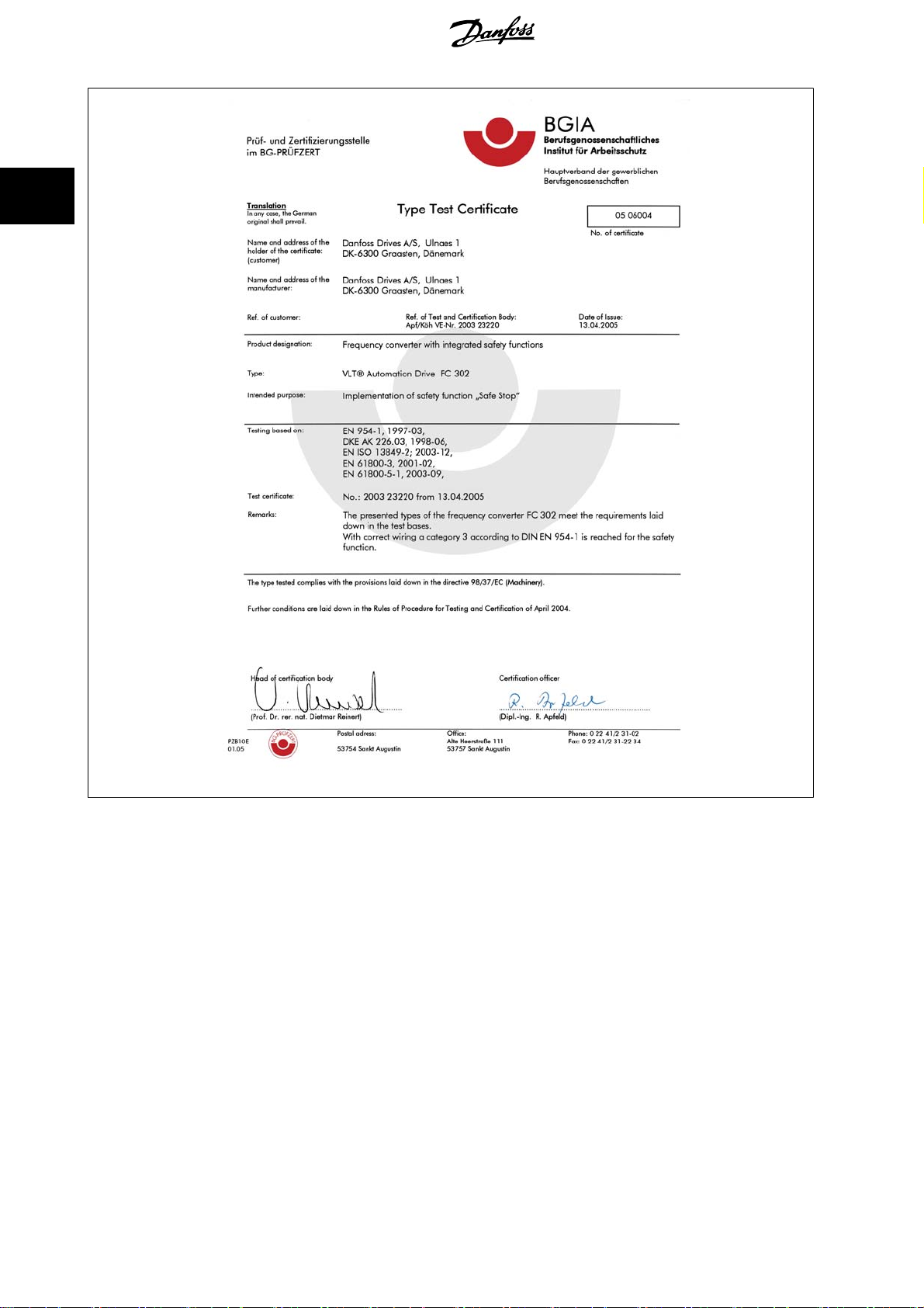
2.1.9 Safe Stop of the frequency converter
For versions fitted with a Safe Stop terminal 37 input, the frequency converter can perform the safety function
IEC 61800-5-2) or
It is designed and approved suitable for the requirements of Safety Category 3 in EN 954-1. This functionality is called Safe Stop. Prior to integration and
use of Safe Stop in an installation, a thorough risk analysis on the installation must be carried out in order to determine whether the Safe Stop functionality
and safety category are appropriate and sufficient. In order to install and use the Safe Stop function in accordance with the requirements of Safety
Category 3 in EN 954-1, the related information and instructions of the must be followed! The information and instructions of the Operating Instructions
are not sufficient for a correct and safe use of the Safe Stop functionality!
Stop Category 0
(as defined in EN 60204-1).
Safe Torque Off
(As defined by draft CD
MG.11.O1.02 - ADAP-KOOL® is a registered Danfoss trademark
9
Page 10
2
2 Safety ADAP-KOOL® Drive AKD 102 High Power
130BA491
10
MG.11.O1.02 - ADAP-KOOL® is a registered Danfoss trademark
Page 11
ADAP-KOOL® Drive AKD 102 High Power 2 Safety
2.1.10 IT mains
IT mains
Do not connect frequency converters with RFI-filters to mains supplies with a voltage between phase and earth of more than 440 V
for 400 V converters and 760 V for 690 V converters.
For 400 V IT mains and delta earth (grounded leg), mains voltage may exceed 440 V between phase and earth.
For 690 V IT mains and delta earth (grounded leg), mains voltage may exceed 760 V between phase and earth.
2
Par. 14-50
RFI Filter
can be used to disconnect the internal RFI capacitors from the RFI filter to ground.
2.1.11 Software Version and Approvals: ADAP-KOOL Drive AKD 102
ADAP-KOOL Drive AKD 102
This manual can be used with all ADAP-KOOL Drive AKD 102 frequency converters with software version 2.1.x.
The software version number can be seen from par. 15-43
Software version: 2.1.x
Software Version
.
2.1.12 Disposal instruction
Equipment containing electrical components must not be disposed of together with domestic waste.
It must be separately collected with electrical and electronic waste according to local and currently valid leg-
islation.
MG.11.O1.02 - ADAP-KOOL® is a registered Danfoss trademark
11
Page 12

3
3 Mechanical Installation ADAP-KOOL® Drive AKD 102 High Power
12
MG.11.O1.02 - ADAP-KOOL® is a registered Danfoss trademark
Page 13
ADAP-KOOL® Drive AKD 102 High Power 3 Mechanical Installation
3 Mechanical Installation
3.1 How to Get Started
3.1.1 About How to Install
This chapter covers mechanical and electrical installations to and from power terminals and control card terminals.
Electrical installation of
options
is described in the relevant Operating Instructions and Design Guide.
3.1.2 How to Get Started
The frequency converter is designed to achieve a quick and EMC-correct installation by following the steps described below.
Read the safety instructions before installing the unit.
3
Mechanical Installation
• Mechanical mounting
Electrical Installation
• Connection to Mains and Protecting Earth
• Motor connection and cables
• Fuses and circuit breakers
• Control terminals - cables
Quick setup
•Local Control Panel, LCP
• Automatic Motor Adaptation, AMA
• Programming
Frame size is depending on enclosure type, power range and mains volt-
age
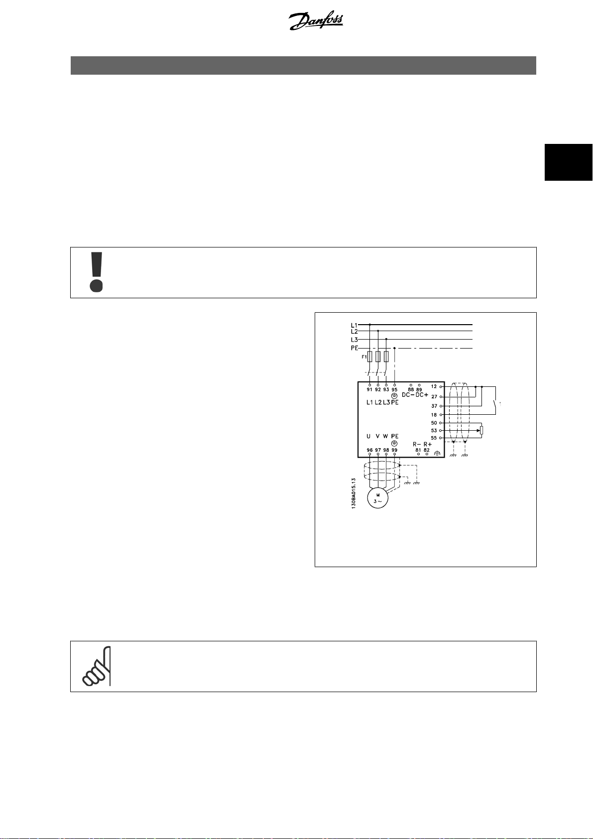
3.2 Pre-installation
Illustration 3.1: Diagram showing basic installation including
mains, motor, start/stop key, and potentiometer for speed
adjustment.
3.2.1 Planning the Installation Site
NB!
Before performing the installation it is important to plan the installation of the frequency converter. Neglecting this may result in extra
work during and after installation.
MG.11.O1.02 - ADAP-KOOL® is a registered Danfoss trademark
13
Page 14
3
3 Mechanical Installation ADAP-KOOL® Drive AKD 102 High Power
Select the best possible operation site by considering the following (see details on the following pages, and the respective Design
Guides):
• Ambient operating temperature
• Installation method
• How to cool the unit
• Position of the frequency converter
•Cable routing
• Ensure the power source supplies the correct voltage and necessary current
• Ensure that the motor current rating is within the maximum current from the frequency converter
• If the frequency converter is without built-in fuses, ensure that the external fuses are rated correctly.
3.2.2 Receiving the Frequency Converter
When receiving the frequency converter please make sure that the packaging is intact, and be aware of any damage that might have occurred to the
unit during transport. In case damage has occurred, contact immediately the shipping company to claim the damage.
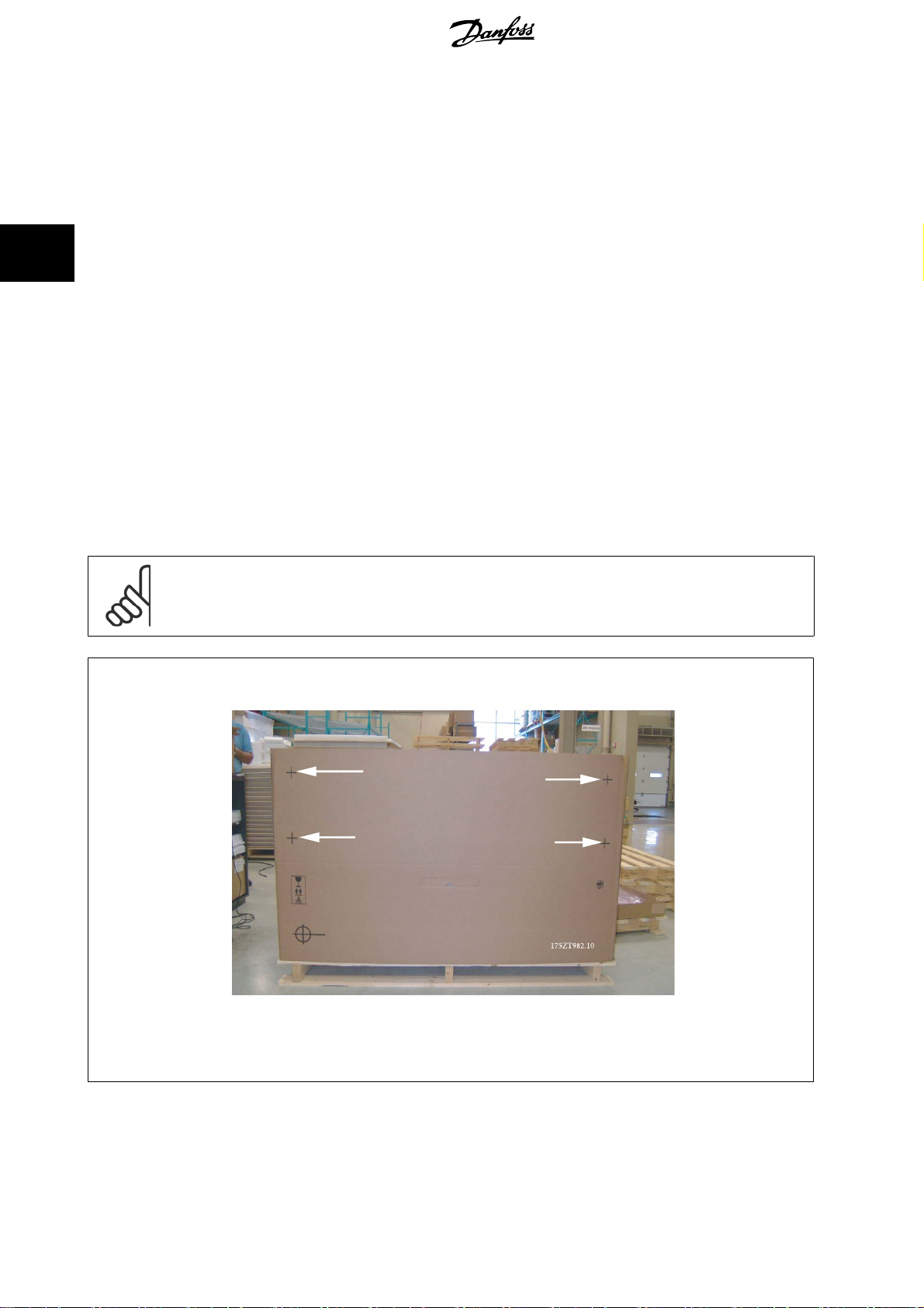
3.2.3 Transportation and Unpacking
Before unpacking the frequency converter it is recommended that it is located as close as possible to the final installation site.
Remove the box and handle the frequency converter on the pallet, as long as possible.
NB!
The card box cover contains a drilling master for the mounting holes in the D frames.
Illustration 3.2: Mounting Template
14
MG.11.O1.02 - ADAP-KOOL® is a registered Danfoss trademark
Page 15
ADAP-KOOL® Drive AKD 102 High Power 3 Mechanical Installation
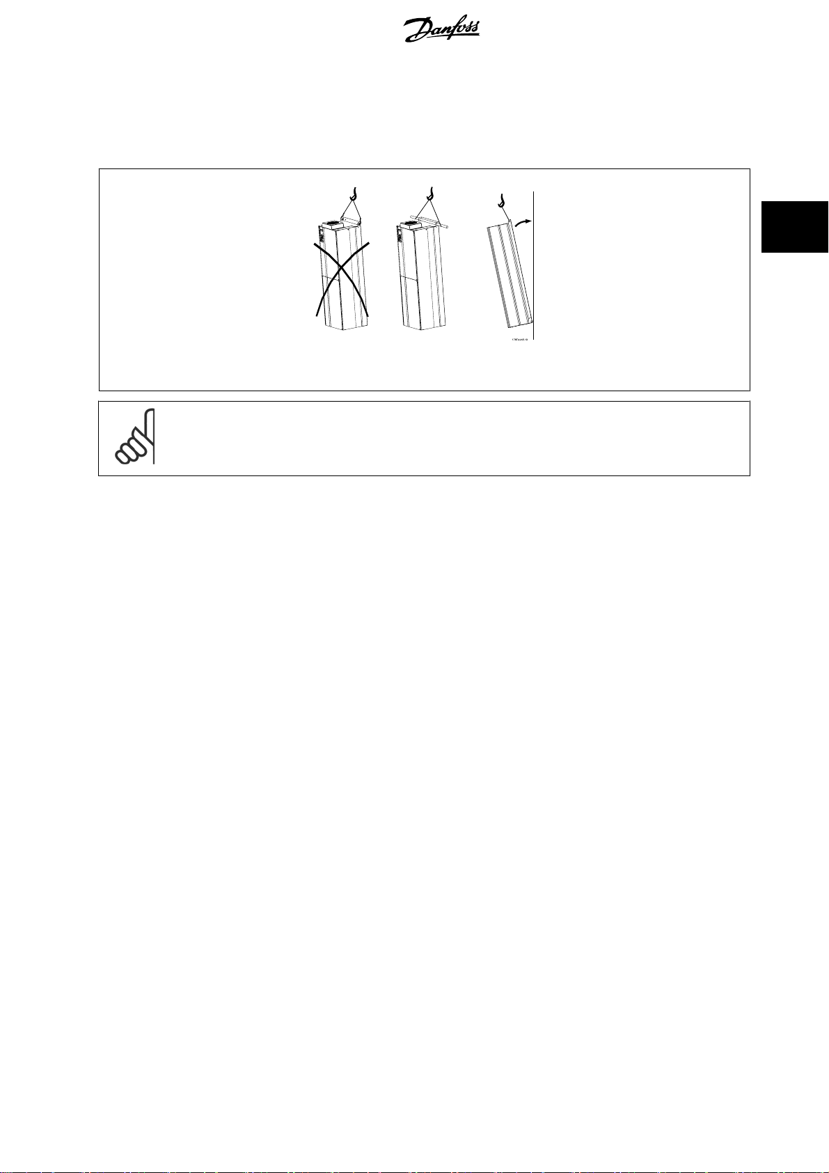
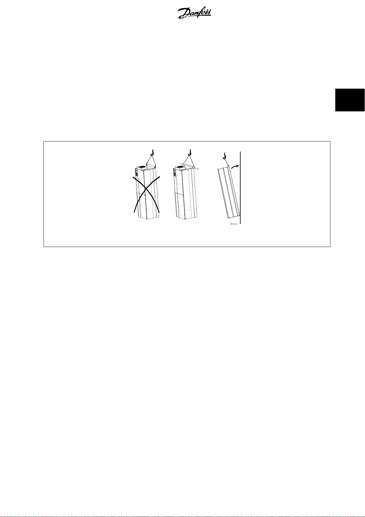
3.2.4 Lifting
Always lift the frequency converter in the dedicated lifting eyes. For all D and E2 (IP00) enclosures, use a bar to avoid bending the lifting holes of the
frequency converter.
3
Illustration 3.3: Recommended lifting method, size D.
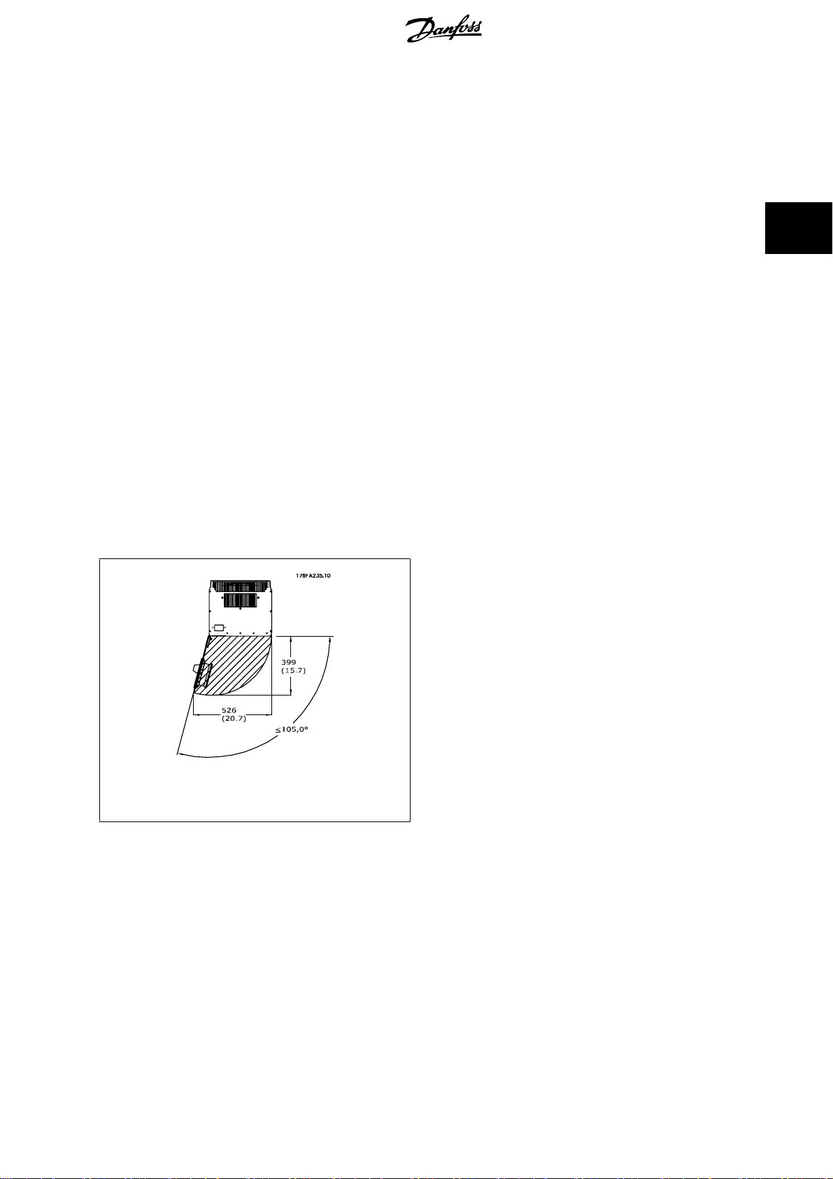
NB!
The lifting bar must be able to handle the weight of the frequency converter. See
frame sizes. Maximum diameter for bar is 2.5 cm (1 inch). The angle from the top of the drive to the lifting cable should be 60° C or
greater.
Mechanical Dimensions
for the weight of the different
MG.11.O1.02 - ADAP-KOOL® is a registered Danfoss trademark
15
Page 16
3
3 Mechanical Installation ADAP-KOOL® Drive AKD 102 High Power
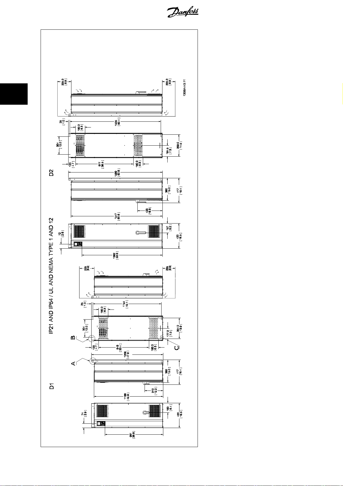
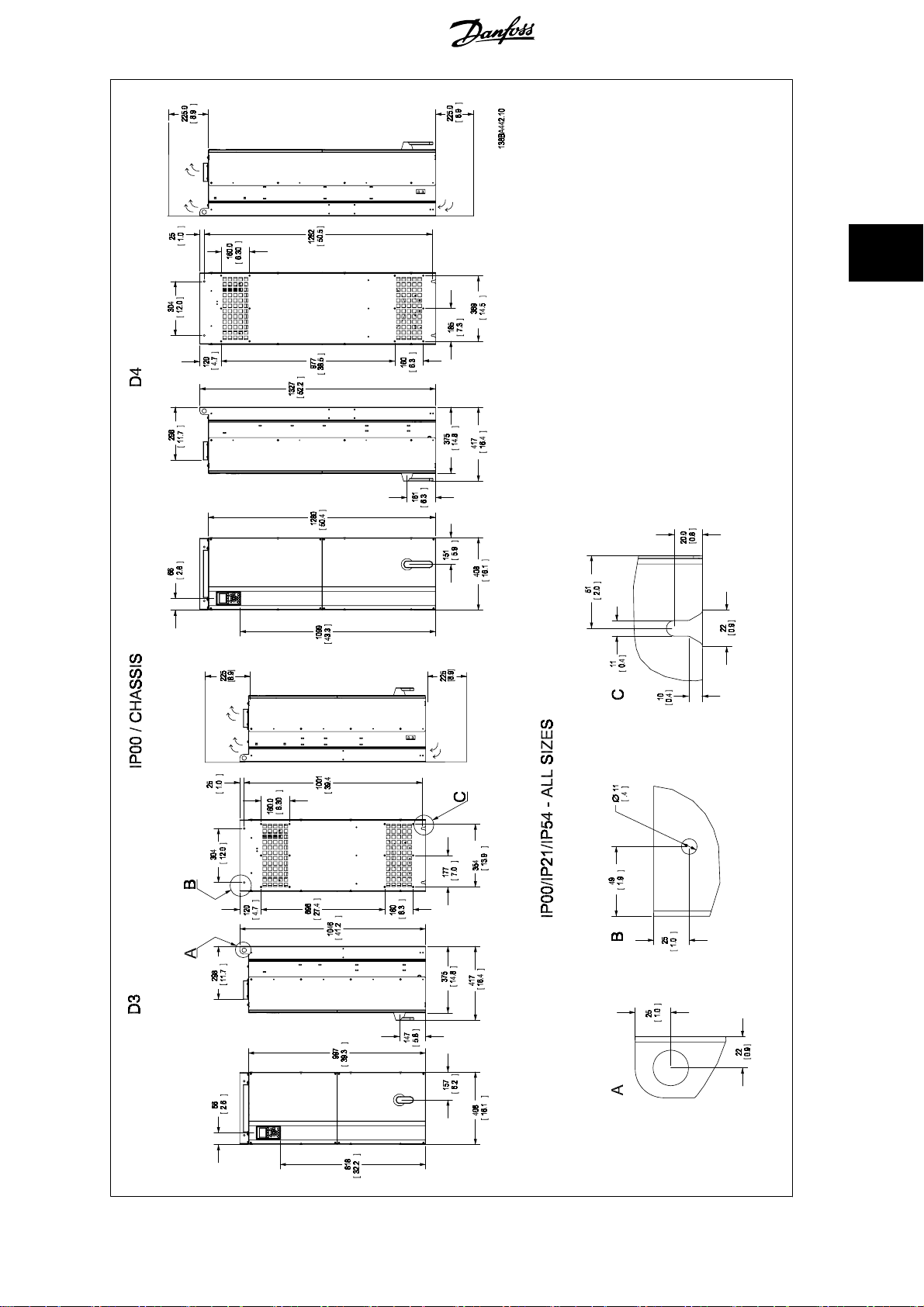
3.2.5 Mechanical Dimensions
16
Please note airflow direct ions
*
MG.11.O1.02 - ADAP-KOOL® is a registered Danfoss trademark
Page 17
ADAP-KOOL® Drive AKD 102 High Power 3 Mechanical Installation
3
MG.11.O1.02 - ADAP-KOOL® is a registered Danfoss trademark
Please note airflow direct ions
*
17
Page 18
3 Mechanical Installation ADAP-KOOL® Drive AKD 102 High Power
3
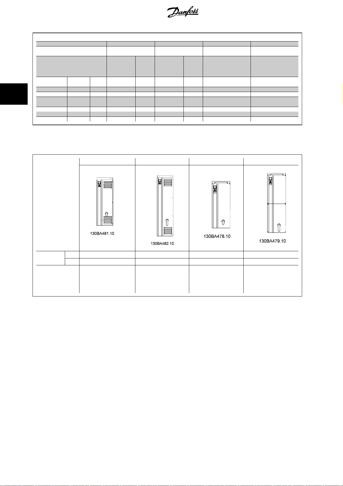
Frame Size D1 D2 D3 D4
IP
NEMA
Shipping dimensions
Drive dimensions
Height
Width 1730 mm 1730 mm 1730 mm 1730 mm 1220 mm 1490 mm
Depth 570 mm 570 mm 570 mm 570 mm 570 mm 570 mm
Height 1209 mm 1209 mm 1589 mm 1589 mm 1046 mm 1327 mm
Width 420 mm 420 mm 420 mm 420 mm 408 mm 408 mm
Depth 380 mm 380 mm 380 mm 380 mm 375 mm 375 mm
Max weight 104 kg 104 kg 151 kg 151 kg 91 kg 138 kg
110 - 132 kW at 400 V
Mechanical dimensions , Frame size D
(380 - 480 V)
21
Type 154Type 1221Type 154Type 12
650 mm 650 mm 650 mm 650 mm 650 mm 650 mm
160 - 250 kW at 400 V
(380 - 480 V)
110 - 132 kW at 400 V
(380 - 480 V)
00
Chassis
160 - 250 kW at 400 V
(380 - 480 V)
3.2.6 Rated Power
Frame size D1 D2 D3 D4
00
Chassis
Enclosure
protection
Normal overload
rated power - 110%
overload torque
IP 21/54 21/54 00 00
NEMA Type 1/ Type 12 Type 1/ Type 12 Chassis Chassis
110 - 132 kW at 400 V
(380 - 480 V)
45 - 160 kW at 690 V
(525-690 V)
150 - 250 kW at 400 V
(380 - 480 V)
200 - 400 kW at 690 V
(525-690 V)
110 - 132 kW at 400 V
(380 - 480 V)
45 - 160 kW at 690 V
(525-690 V)
150 - 250 kW at 400 V
(380 - 480 V)
200 - 400 kW at 690 V
(525-690 V)
18
MG.11.O1.02 - ADAP-KOOL® is a registered Danfoss trademark
Page 19
ADAP-KOOL® Drive AKD 102 High Power 3 Mechanical Installation
3.3 Mechanical Installation
Pre pa ra tion of the me ch an ic al installatio n o f t he frequency co nv er te r must be do ne ca refu lly to ensu re a p roper resu lt an d t o avoid additional work during
installation. Start taking a close look at the mechanical drawings at the end of this instruction to become familiar with the space demands.
3.3.1 Tools Needed
To perform the mechanical installation the following tools are needed:
• Drill with 10 or 12 mm drill
• Tape measure
• Wrench with relevant metric sockets (7-17 mm)
• Extensions to wrench
• Sheet metal punch for conduits or cable glands in IP 21/Nema 1 and IP 54 units
• Lifting bar to lift the unit (rod or tube max. Ø 25 mm (1 inch), able to lift minimum 400 kg (880 lbs)).
• Crane or other lifting aid to place the frequency converter in position
• A Torx T50 tool is needed to install the E1 in IP21 and IP54 enclosure types.
3.3.2 General Considerations
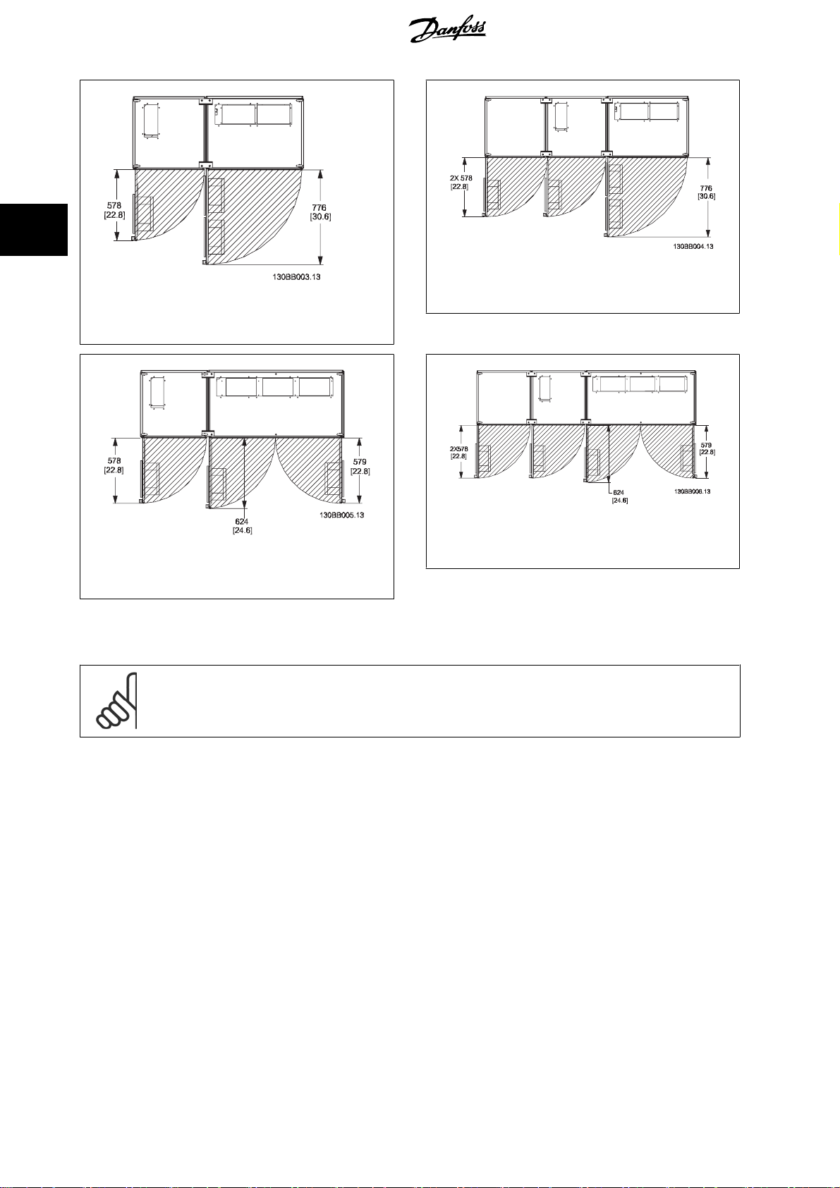
Space
Ensure proper space above and below the frequency converter to allow airflow and cable access. In addition space in front of the unit must be considered
to enable opening of the door of the panel.
3
Illustration 3.4: Space in front of IP21/IP54 enclosure type,
frame size D1 and D2 .
MG.11.O1.02 - ADAP-KOOL® is a registered Danfoss trademark
19
Page 20
3
3 Mechanical Installation ADAP-KOOL® Drive AKD 102 High Power
Illustration 3.6: Space in front of IP21/IP54 enclosure type,
frame size F3
Illustration 3.5: Space in front of IP21/IP54 enclosure type,
frame size F1
Illustration 3.8: Space in front of IP21/IP54 enclosure type,
Illustration 3.7: Space in front of IP21/IP54 enclosure type,
frame size F2
Wire access
Ensure that proper cable access is present including necessary bending allowance. As the IP00 enclosure is open to the bottom cables must be fixed to
the back panel of the enclosure where the frequency converter is mounted, i.e. by using cable clamps.
NB!
All cable lugs/ shoes must mount within the width of the terminal bus bar
frame size F4
20
MG.11.O1.02 - ADAP-KOOL® is a registered Danfoss trademark
Page 21
ADAP-KOOL® Drive AKD 102 High Power 3 Mechanical Installation
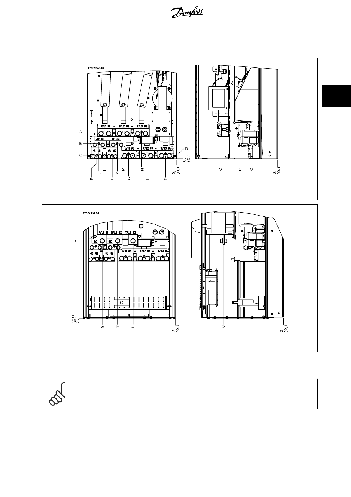
3.3.3 Terminal Locations - Frame size D
Take the following position of the terminals into consideration when you design for cables access.
3
Illustration 3.9: Position of power connections, frame size D3 and D4
Illustration 3.10: Position of power connections with disconnect switch, frame size D1 and D2
Be aware that the power cables are heavy and hard to bend. Consider the optimum position of the frequency converter for ensuring easy installation of
the cables.
NB!
All D frames are available with standard input terminals or disconnect switch. All terminal dimensions can be found in the following
table.
MG.11.O1.02 - ADAP-KOOL® is a registered Danfoss trademark
21
Page 22
3
3 Mechanical Installation ADAP-KOOL® Drive AKD 102 High Power
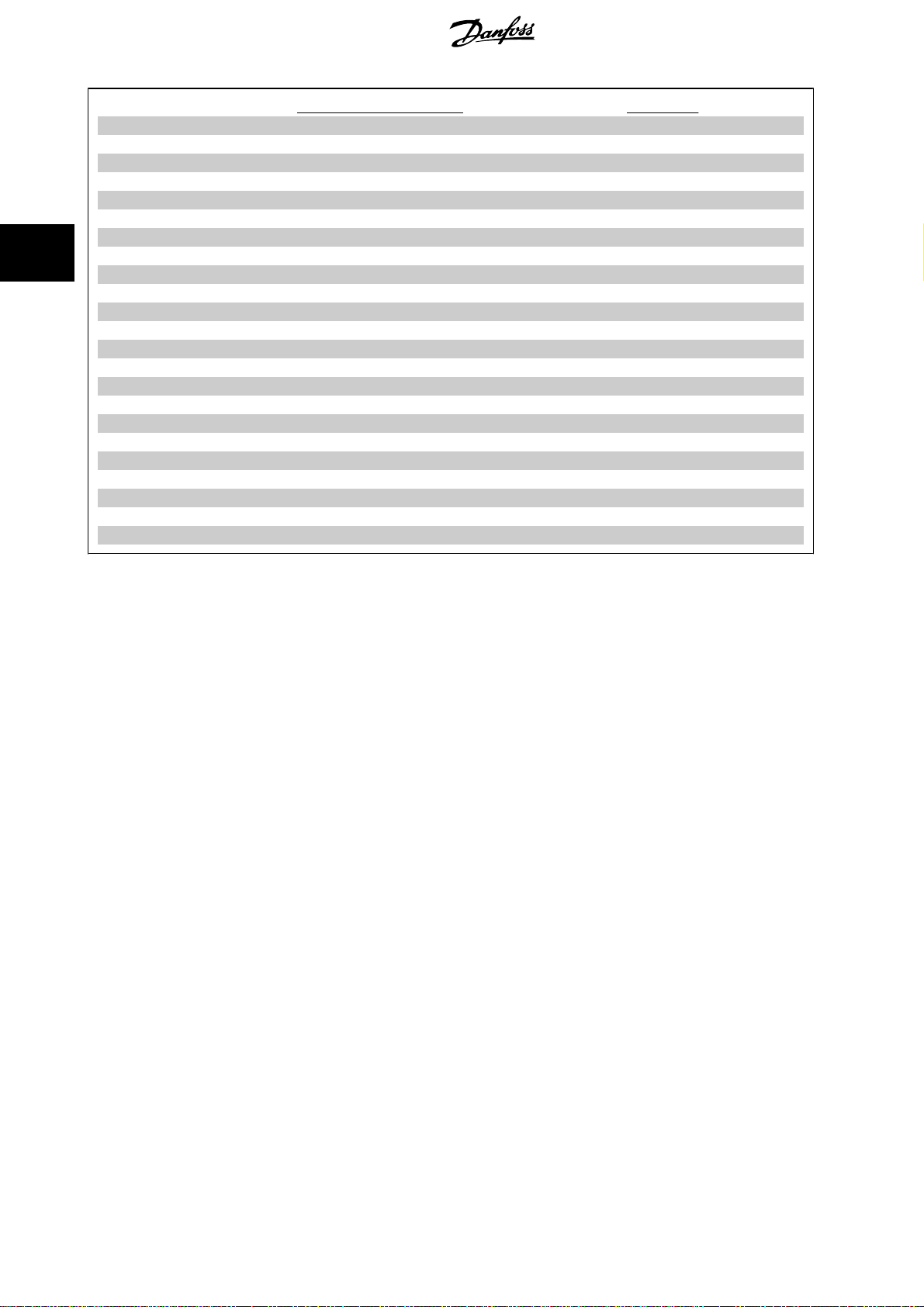
IP 21 (NEMA 1) / IP 54 (NEMA 12) IP 00 / Chassis
Frame size D1 Frame size D2 Frame size D3 Frame size D4
A 277 (10.9) 379 (14.9) 119 (4.7) 122 (4.8)
B 227 (8.9) 326 (12.8) 68 (2.7) 68 (2.7)
C 173 (6.8) 273 (10.8) 15 (0.6) 16 (0.6)
D 179 (7.0) 279 (11.0) 20.7 (0.8) 22 (0.8)
E 370 (14.6) 370 (14.6) 363 (14.3) 363 (14.3)
F 300 (11.8) 300 (11.8) 293 (11.5) 293 (11.5)
G 222 (8.7) 226 (8.9) 215 (8.4) 218 (8.6)
H 139 (5.4) 142 (5.6) 131 (5.2) 135 (5.3)
I 55 (2.2) 59 (2.3) 48 (1.9) 51 (2.0)
J 354 (13.9) 361 (14.2) 347 (13.6) 354 (13.9)
K 284 (11.2) 277 (10.9) 277 (10.9) 270 (10.6)
L 334 (13.1) 334 (13.1) 326 (12.8) 326 (12.8)
M 250 (9.8) 250 (9.8) 243 (9.6) 243 (9.6)
N 167 (6.6) 167 (6.6) 159 (6.3) 159 (6.3)
O 261 (10.3) 260 (10.3) 261 (10.3) 261 (10.3)
P 170 (6.7) 169 (6.7) 170 (6.7) 170 (6.7)
Q 120 (4.7) 120 (4.7) 120 (4.7) 120 (4.7)
R 256 (10.1) 350 (13.8) 98 (3.8) 93 (3.7)
S 308 (12.1) 332 (13.0) 301 (11.8) 324 (12.8)
T 252 (9.9) 262 (10.3) 245 (9.6) 255 (10.0)
U 196 (7.7) 192 (7.6) 189 (7.4) 185 (7.3)
V 260 (10.2) 273 (10.7) 260 (10.2) 273 (10.7)
Table 3.1: Cable positions as shown in drawings above. Dimensions in mm (inch).
22
MG.11.O1.02 - ADAP-KOOL® is a registered Danfoss trademark
Page 23
ADAP-KOOL® Drive AKD 102 High Power 3 Mechanical Installation
3.3.4 Cooling and Airflow
Cooling
Cooling can be obtained in different ways, by using the cooling ducts in the bottom and the top of the unit, by taking air in and out the back of the unit
or by combining the cooling possibilities.
Duct cooling
A dedicated option has been developed to optimize installation of IP00/chassis frequency converters in Rittal TS8 enclosures utilizing the fan of the
frequency converter for forced air cooling of the backchannel. The air out the top of the enclosure could but ducted outside a facility so the heat loses
from the backchannel are not dissipated within the control room reducing air-conditioning requirements of the facility.
Please see
Back cooling
The backchannel air can also be ventilated in and out the back of a Rittal TS8 enclosure. This offers a solution where the backchannel could take air from
outside the facility and return the heat loses outside the facility thus reducing air-conditioning requirements.
Installation of Duct Cooling Kit in Rittal enclosures
NB!
A doorfan(s) is required on the enclosure to remove the heat losses not contained in the backchannel of the drive and any additional
losses generated from other components installed inside the enclosure. The total required air flow must be calculated so that the
appropriate fans can be selected. Some enclosure manufacturers offer software for performing the calculations (i.e. Rittal Therm
software). If the drive is the only heat generating component in the enclosure, the minimum airflow required at an ambient temperature
o
of 45
C for the D3 and D4 drives is 391 m3/h (230 cfm).
, for further information.
3
Airflow
The necessary airflow over the heat sink must be secured. The flow rate is shown below.
Enclosure protection
IP21 / NEMA 1 D1 and D2
IP00 / Chassis D3 and D4
Table 3.2: Heatsink Air Flow
NB!
The fan runs for the following reasons:
1. AMA
2. DC Hold
3. Pre-Mag
4. DC Brake
5. 60% of nominal current is exceeded
6. Specific heatsink temperature exceeded (power size dependent).
Once the fan is started it will run for minimum 10 minutes.
Frame size Door fan / Top fan airflow Airflow over heatsink
170 m3/h (100 cfm) 765 m3/h (450 cfm)
3
/h (150 cfm) 765 m3/h (450 cfm)
255 m
MG.11.O1.02 - ADAP-KOOL® is a registered Danfoss trademark
23
Page 24
3
3 Mechanical Installation ADAP-KOOL® Drive AKD 102 High Power
External ducts
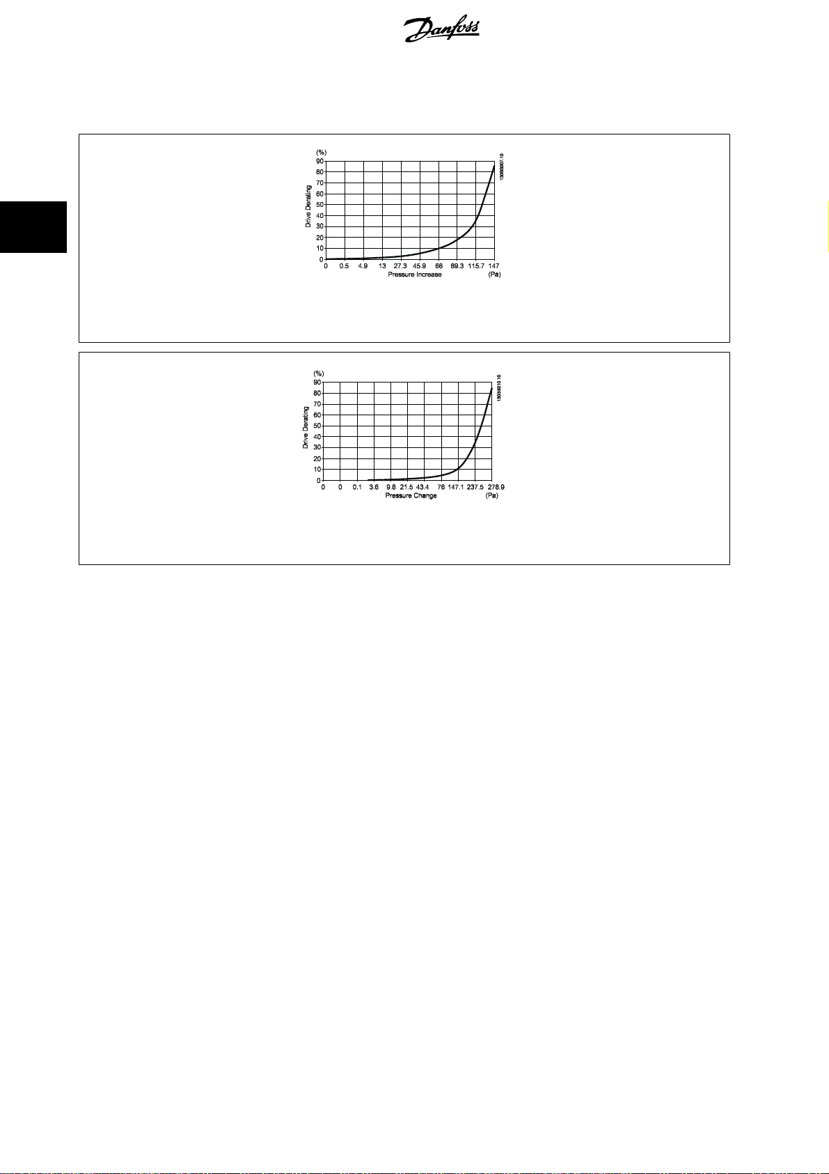
If additional duct work is added externally to the Rittal cabinet the pressure drop in the ducting must be calculated. Use the charts below to derate the
frequency converter according to the pressure drop.
Illustration 3.11: D frame Derating vs. Pressure Change
Drive air flow: 450 cfm (765 m
3
/h)
Illustration 3.12: E frame Derating vs. Pressure Change (Small Fan), P250T5 and P355T7-P400T7
3
Drive air flow: 650 cfm (1105 m
/h)
24
MG.11.O1.02 - ADAP-KOOL® is a registered Danfoss trademark
Page 25
ADAP-KOOL® Drive AKD 102 High Power 3 Mechanical Installation
3.3.5 Installation on the Wall - IP21 (NEMA 1) and IP54 (NEMA 12) Units
This only applies to frame sizes D1 and D2 . It must be considered where to install the unit.
Take the relevant points into consideration before you select the final installation site:
• Free space for cooling
• Access to open the door
• Cable entry from the bottom
Mark the mounting holes carefully using the mounting template on the wall and drill the holes as indicated. Ensure proper distance to the floor and the
ceiling for cooling. A minimum of 225 mm (8.9 inch) below the frequency converter is needed. Mount the bolts at the bottom and lift the frequency
converter up on the bolts. Tilt the frequency converter against the wall and mount the upper bolts. Tighten all four bolts to secure the frequency converter
against the wall.
3
Illustration 3.13: Lifting method for mounting drive on wall
MG.11.O1.02 - ADAP-KOOL® is a registered Danfoss trademark
25
Page 26
3
3 Mechanical Installation ADAP-KOOL® Drive AKD 102 High Power
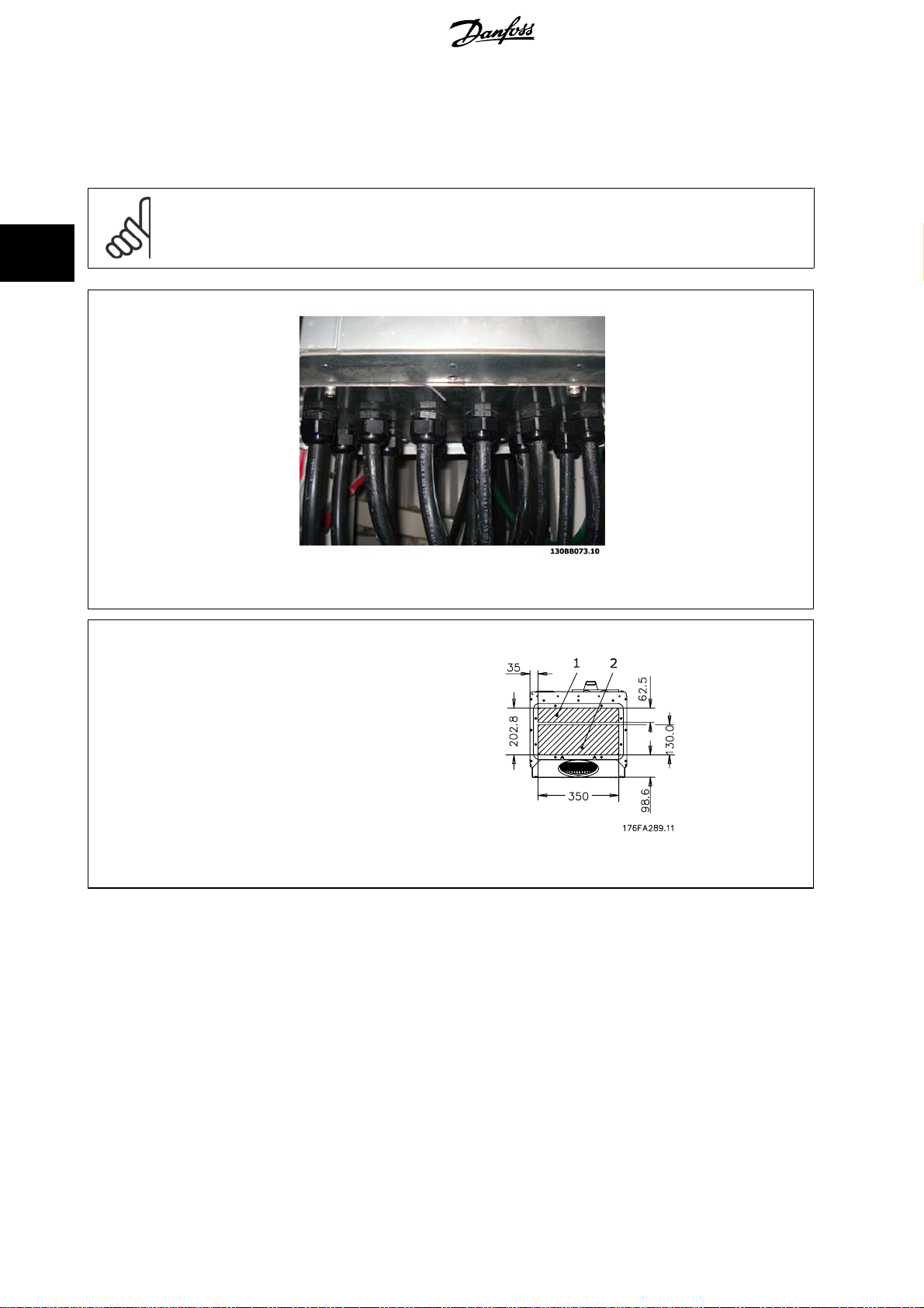
3.3.6 Gland/Conduit Entry - IP21 (NEMA 1) and IP54 (NEMA12)
Cables are connected through the gland plate from the bottom. Remove the plate and plan where to place the entry for the glands or conduits. Prepare
holes in the marked area on the drawing.
NB!
The gland plate must be fitted to the frequency converter to ensure the specified protection degree, as well as ensuring proper cooling
of the unit. If the gland plate is not mounted, the frequency converter may trip on Alarm 69, Pwr. Card Temp
Illustration 3.14: Example of proper installation of the gland plate.
Frame size D1 + D2
Cable entries viewed from the bottom of the frequency converter - 1) Mains side 2) Motor side
26
MG.11.O1.02 - ADAP-KOOL® is a registered Danfoss trademark
Page 27
ADAP-KOOL® Drive AKD 102 High Power 3 Mechanical Installation
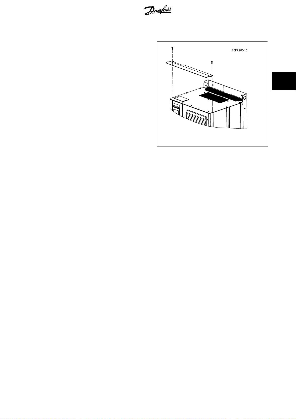
3.3.7 IP21 Drip Shield Installation (Frame size D1 and D2 )
To comply with the IP21 rating, a separate drip shi eld is to be
installed as explained below:
• Remove the two front screws
• Insert the drip shield and replace screws
• Torque the screws to 5,6 Nm (50 in-lbs)
3
Illustration 3.15: Drip shield installation.
MG.11.O1.02 - ADAP-KOOL® is a registered Danfoss trademark
27
Page 28
3
3 Mechanical Installation ADAP-KOOL® Drive AKD 102 High Power
3.4 Field Installation of Options
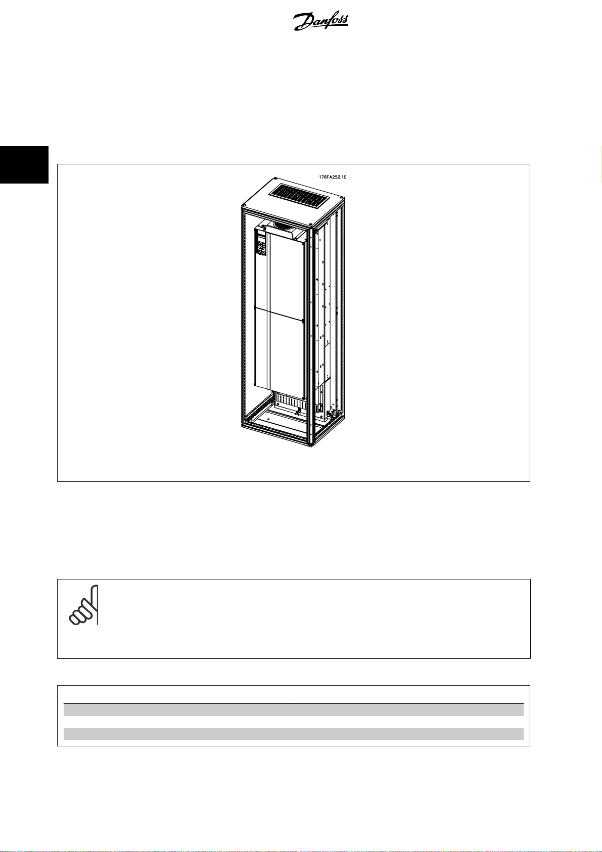
3.4.1 Installation of Duct Cooling Kit in Rittal Enclosures
This section deals with the installation of IP00 / chassis enclosed frequency converters with duct work cooling kits in Rittal enclosures. In addition to the
enclosure a 200 mm base/plinth is required.
Illustration 3.16: Installation of IP00 in Rittal TS8 enclosure.
The minimum enclosure dimension is:
• D3 and D4 frame: Depth 500 mm and width 600 mm.
The maximum depth and width are as required by the installation. When using multiple frequency converters in one enclosure it is recommended that
each drive is mounted on its own back panel and supported along the mid-section of the panel. These duct work kits do not support the “in frame”
mounting of the panel (see Rittal TS8 catalogue for details). The duct work cooling kits listed in the table below are suitable for use only with IP 00 /
Chassis frequency converters in Rittal TS8 IP 20 and UL and NEMA 1 and IP 54 and UL and NEMA 12 enclosures.
NB!
A doorfan(s) is required on the enclosure to remove the heat losses not contained in the backchannel of the drive and any additional
losses generated from other components installed inside the enclosure. The total required air flow must be calculated so that the
appropriate fans can be selected. Some enclosure manufacturers offer software for performing the calculations (i.e. Rittal Therm
software). If the drive is the only heat generating component in the enclosure, the minimum airflow required at an ambient temperature
o
C for the D3 and D4 drives is 391 m3/h (230 cfm).
of 45
Ordering Information
Rittal TS-8 Enclosure
1800 mm 176F1824 176F1823
2000 mm 176F1826 176F1825
Frame D3 Kit Part No. Frame D4Kit Part No.
28
MG.11.O1.02 - ADAP-KOOL® is a registered Danfoss trademark
Page 29
ADAP-KOOL® Drive AKD 102 High Power 3 Mechanical Installation
NB!
Please see the
External ducts
If additional duct work is added externally to the Rittal cabinet the pressure drop in the ducting must be calculated. Please see section
for further information.
Airflow
3.4.2 Outside Installation/ NEMA 3R Kit for Rittal Enclosures
Duct Kit Instruction Manual, 175R5640,
for further information
Cooling and
3
This section is for the installation of NEMA 3R kits available for the frequency converter frames D3 and D4 . These kits are designed and tested to be
used with IP00/ Chassis versions of these frames in Rittal TS8 NEMA 3R or NEMA 4 enclosures. The NEMA-3R enclosure is an outdoor enclosure that
provides a degree of protection against rain and ice. The NEMA-4 enclosure is an outdoor enclosure that provides a greater degree of protection against
weather and hosed water.
The minimum enclosure depth is 500 mm (600 mm for E2 frame) and the kit is designed for a 600 mm (800 mm for E2 frame) wide enclosure. Other
enclosure widths are possible, however additional Rittal hardware is required. The maximum depth and width are as required by the installation.
NB!
The current rating of drives in D3 and D4 frames are de-rated by 3%, when adding the NEMA 3R kit. Drives in E2 frames require no
derating
NB!
A doorfan(s) is required on the enclosure to remove the heat losses not contained in the backchannel of the drive and any additional
losses generated from other components installed inside the enclosure. The total required air flow must be calculated so that the
appropriate fans can be selected. Some enclosure manufacturers offer software for performing the calculations (i.e. Rittal Therm
software). If the drive is the only heat generating component in the enclosure, the minimum airflow required at an ambient temperature
o
of 45
C for the D3 and D4 drives is 391 m3/h (230 cfm).
Ordering information
Frame size D3: 176F4600
Frame size D4: 176F4601
Frame size E2: 176F1852
NB!
Please see the instructions
175R5922
for further information
MG.11.O1.02 - ADAP-KOOL® is a registered Danfoss trademark
29
Page 30
3 Mechanical Installation ADAP-KOOL® Drive AKD 102 High Power
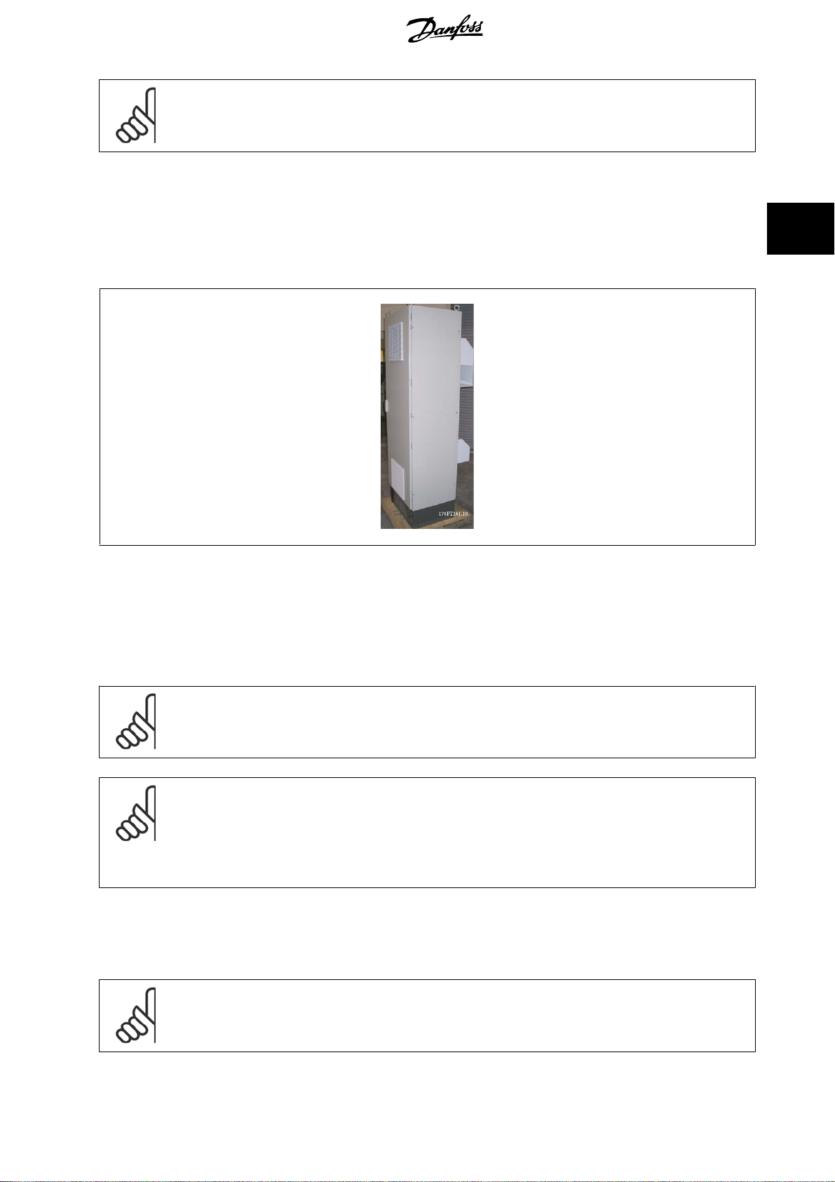
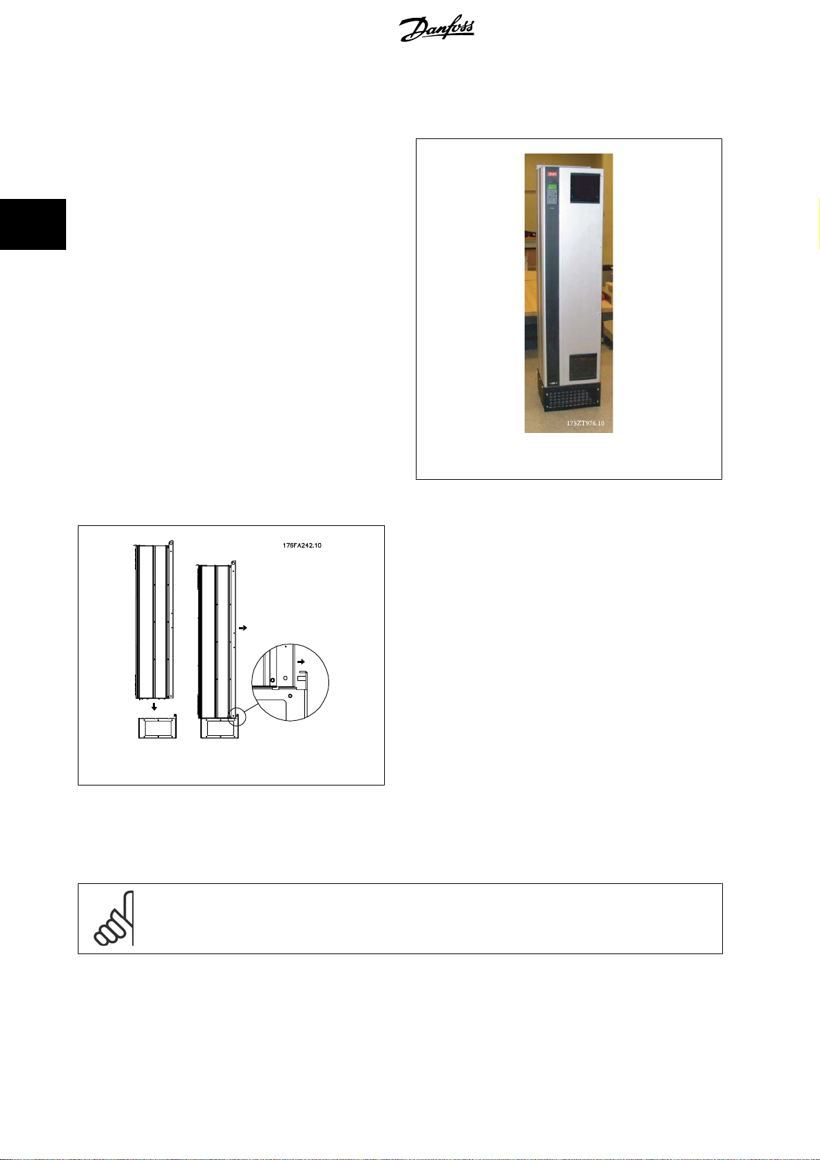
3.4.3 Installation on Pedestal
This section describes the installation of a pedestal unit available for the
frequency converters frames D1 and D2. This is a 200 mm high pedestal
that allows these frames to be floor mounted. The front of the pedestal
has openings for input air to the power components.
3
The frequency converter gland plate must be installed to provide ade-
quate cooling air to the control components of the frequency converter
via the door fan and to maintain the IP21/NEMA 1 or IP54/NEMA 12 de-
grees of enclosure protections.
Illustration 3.17: Drive on pedestal
There is one pedestal that fits both frames D1 and D2. Its ordering number is 176F1827. The pedestal is standard for E1 frame.
Illustration 3.18: Mounting of drive to pedestal.
3.4.4 Installation of Input Plate Options
This section is for the field installation of input option kits available for frequency converters in all D and E frames.
Do not attempt to remove RFI filters from input plates. Damage may occur to RFI filters if they are removed from the input plate.
NB!
Where RFI filters are available, there are two different type of RFI filters depending on the input plate combination and the RFI filters
interchangeable. Field installable kits in certain cases are the same for all voltages.
30
MG.11.O1.02 - ADAP-KOOL® is a registered Danfoss trademark
Page 31

ADAP-KOOL® Drive AKD 102 High Power 3 Mechanical Installation
380 - 480 V
380 - 500 V
D1 All D1 power sizes 176F8442 176F8450 176F8444 176F8448 176F8446
D2 All D2 power sizes 176F8443 176F8441 176F8445 176F8449 176F8447
525 - 690 V Fuses Disconnect Fuses RFI RFI Fuses RFI Disconnect
D1 AKD 102/ : 45-90 kW
: 37-75 kW
AKD 102/ : 110-160 kW
: 90-132 kW
D2 All D2power sizes 175L8827 175L8826 175L8825 NA NA
NB!
For further information, please see the Instruction Sheet,
Fuses Disconnect Fuses RFI RFI Fuses RFI Disconnect
Fuses
Fuses
175L8829 175L8828 175L8777 NA NA
175L8442 175L8445 175L8777 NA NA
175R5795
3.4.5 Installation of Mains Shield for Frequency Converters
This section is for the installation of a mains shield for the frequency converter series with D1, D2 and E1 frames. It is not possible to install in the IP00/
Chassis versions as these have included as standard a metal cover. These shields satisfy VBG-4 requirements.
3
Ordering numbers:
Frames D1 and D2 : 176F0799
NB!
For further information, please see the Instruction Sheet,
175R5923
MG.11.O1.02 - ADAP-KOOL® is a registered Danfoss trademark
31
Page 32

4
4 Electrical Installation ADAP-KOOL® Drive AKD 102 High Power
32
MG.11.O1.02 - ADAP-KOOL® is a registered Danfoss trademark
Page 33

ADAP-KOOL® Drive AKD 102 High Power 4 Electrical Installation
4 Electrical Installation
4.1 Electrical Installation
4.1.1 Power Connections
Cabling and Fusing
NB!
Cables General
All cabling must comply with national and local regulations on cable cross-sections and ambient temperature. UL applications require
75 °C copper conductors. 75 and 90 °C copper conductors are thermally acceptable for the frequency converter to use in non UL
applications.
The power cable connections are situated as shown below. Dimensioning of cable cross section must be done in accordance with the current ratings and
local legislation. See the
For protection of the frequency converter, the recommended fuses must be used or the unit must be with built-in fuses. Recommended fuses can be
seen in the tables of the fuse section. Always ensure that proper fusing is made according to local regulation.
Specifications section
for details.
4
The mains connection is fitted to the mains switch if this is included.
NB!
The motor cable must be screened/armoured. If an unscreened/unarmoured cable is used, some EMC requirements are not complied
with. Use a screened/armoured motor cable to comply with EMC emission specifications. For more information, see
tions
in the
Design Guide
See section
Screening of cables:
Avoid installation with twisted screen ends (pigtails). They spoil the screening effect at higher frequencies. If it is necessary to break the screen to install
a motor isolator or motor contactor, the screen must be continued at the lowest possible HF impedance.
Connect the motor cable screen to both the de-coupling plate of the frequency converter and to the metal housing of the motor.
Make the screen connections with the largest possible surface area (cable clamp). This is done by using the supplied installation devices within the
frequency converter.
Cable-length and cross-section:
The frequency converter has been EMC tested with a given length of cable. Keep the motor cable as short as possible to reduce the noise level and
leakage currents.
Switching frequency:
When frequency converters are used together with Sine-wave filters to reduce the acoustic noise from a motor, the switching frequency must be set
according to the instruction in par. 14-01
General Specifications
.
for correct dimensioning of motor cable cross-section and length.
Switching Frequency
.
EMC specifica-
MG.11.O1.02 - ADAP-KOOL® is a registered Danfoss trademark
33
Page 34

4 Electrical Installation ADAP-KOOL® Drive AKD 102 High Power
4
Term. no. 96 97 98 99
U1 V1 W1
U1 V1 W1
1)
Protected Earth Connection
U V W
W2 U2 V2 6 wires out of motor
1)
PE
1)
PE
1)
PE
Motor voltage 0-100% of mains voltage.
3 wires out of motor
Delta-connected
Star-connected U2, V2, W2
U2, V2 and W2 to be interconnected separately.
NB!
In motors without phase insulation paper or other in-
sulation reinforcement suitable for operation with volt-
age supply (such as a frequency converter), fit a Sine-
wave filter on the output of the frequency converter.
Illustration 4.1: Compact IP 21 (NEMA 1) and IP 54 (NEMA 12), frame size D1
Illustration 4.2: Compact IP 21 (NEMA 1) and IP 54 (NEMA 12) with disconnect, fuse and RFI filter, frame size D2
34
MG.11.O1.02 - ADAP-KOOL® is a registered Danfoss trademark
Page 35

ADAP-KOOL® Drive AKD 102 High Power 4 Electrical Installation
1) AUX Relay 5) Brake
01 02 03 -R +R
04 05 06 81 82
2) Temp Switch 6) SMPS Fuse (see fuse tables for part number)
106 104 105 7) AUX Fan
3) Line 100 101 102 103
R S T L1 L2 L1 L2
91 92 93 8) Fan Fuse (see fuse tables for part number)
L1 L2 L3 9) Mains ground
4) Load sharing 10) Motor
-DC +DC U V W
88 89 96 97 98
T1 T2 T3
4
Illustration 4.3: Compact IP 00 (Chassis), frame size D3
Illustration 4.4: Compact IP 00 (Chassis) with disconnect, fuse and RFI filter, frame size D4
MG.11.O1.02 - ADAP-KOOL® is a registered Danfoss trademark
35
Page 36

4
4 Electrical Installation ADAP-KOOL® Drive AKD 102 High Power
1) AUX Relay 5) Brake
01 02 03 -R +R
04 05 06 81 82
2) Temp Switch 6) SMPS Fuse (see fuse tables for part number)
106 104 105 7) AUX Fan
3) Line 100 101 102 103
R S T L1 L2 L1 L2
91 92 93 8) Fan Fuse (see fuse tables for part number)
L1 L2 L3 9) Mains ground
4) Load sharing 10) Motor
-DC +DC U V W
88 89 96 97 98
T1 T2 T3
Illustration 4.5: Position of earth terminals IP00, frame sizes
D
NB!
D2 and D4 shown as examples. D1 and D3 are equivalent.
Illustration 4.6: Position of earth terminals IP21 (NEMA type
1) and IP54 (NEMA type 12)
36
MG.11.O1.02 - ADAP-KOOL® is a registered Danfoss trademark
Page 37

ADAP-KOOL® Drive AKD 102 High Power 4 Electrical Installation
4.1.2 Earthing
The following basic issues need to be considered when installing a frequency converter, so as to ob tain electr omagnetic c ompati bility
(EMC).
• Safety earthing: Please note that the frequency converter has a high leakage current and must be earthed appropriately for safety reasons.
Apply local safety regulations.
• High-frequency earthing: Keep the earth wire connections as short as possible.
Connect the different earth systems at the lowest possible conductor impedance. The lowest possible conductor impedance is obtained by keeping the
conductor as short as possible and by using the greatest possible surface area.
The metal cabinets of the different devices are mounted on the cabinet rear plate using the lowest possible HF impedance. This avoids having different
HF voltages for the individual devices and avoids the risk of radio interference currents running in connection cables that may be used between the
devices. The radio interference will have been reduced.
In order to obtain a low HF impedance, use the fastening bolts of the devices as HF connection to the rear plate. It is necessary to remove insulating
paint or similar from the fastening points.
4.1.3 Extra Protection (RCD)
ELCB relays, multiple protective earthing or earthing can be used as extra protection, provided that local safety regulations are complied with.
In the case of an earth fault, a DC component may develop in the fault current.
4
If ELCB relays are used, local regulations must be observed. Relays must be suitable for protection of 3-phase equipment with a bridge rectifier and for
a brief discharge on power-up.
See also the section
Special Conditions
in the Design Guide.
4.1.4 RFI Switch
Mains supply isolated from earth
If the frequency converter is supplied from an isolated mains source (, floating delta and grounded delta) or TT/TN-S mains with grounded leg, the RFI
switch is recommended to be turned off (OFF) via par. 14-50
needed, parallel motors are connected or the motor cable length is above 25 m, it is recommended to set par. 14-50
In OFF, the internal RFI capacities (filter capacitors) between the chassis and the intermediate circuit are cut off to avoid damage to the intermediate
circuit and to reduce the earth capacity currents (according to IEC 61800-3).
Please also refer to the application note
power electronics (IEC 61557-8).
VLT on IT mains, MN.90.CX.02.
RFI Filter
. For further reference, see IEC 364-3. In case optimum EMC performance is
RFI Filter
to [ON].
It is important to use isolation monitors that are capable for use together with
MG.11.O1.02 - ADAP-KOOL® is a registered Danfoss trademark
37
Page 38

4
4 Electrical Installation ADAP-KOOL® Drive AKD 102 High Power
4.1.5 Torque
When tightening all electrical connections it is very important to tighten
with the correct torque. Too low or too high torque results in a bad elec-
trical connection. Use a torque wrench to ensure correct torque
Illustration 4.7: Always use a torque wrench to tighten the
bolts.
Frame size Terminal Torque Bolt size
D1, D2, D3 and D4 Mains
Motor
Load sharing
Brake
19 Nm (168 in-lbs) M10
9.5 Nm (84 in-lbs) M8
4.1.6 Shielded Cables
It is important that shielded and armoured cables are connected in a proper way to ensure high EMC immunity and low emissions.
Connection can be made using either cable glands or clamps:
• EMC cable glands: Generally available cable glands can be used to ensure an optimum EMC connection.
• EMC cable clamp: Clamps allowing easy connection are supplied with the frequency converter.
4.1.7 Motor Cable
The motor must be connected to terminals U/T1/96, V/T2/97, W/T3/98. Earth to terminal 99. All types of three-phase asynchronous standard motors
can be used with a frequency converter unit. The factory setting is for clockwise rotation with the frequency converter output connected as follows:
Terminal No.
96, 97, 98, 99 Mains U/T1, V/T2, W/T3
Function
Earth
38
MG.11.O1.02 - ADAP-KOOL® is a registered Danfoss trademark
Page 39

ADAP-KOOL® Drive AKD 102 High Power 4 Electrical Installation
• Terminal U/T1/96 connected to U-phase
• Terminal V/T2/97 connected to V-phase
• Terminal W/T3/98 connected to W-phase
4
The direction of rotation can be changed by switching two phases in the motor cable or by changing the setting of par. 4-10
Motor rotation check can be performed using par.1-28
Motor Rotation Check
and following the steps shown in the display.
Motor Speed Direction
4.1.8 Load Sharing
Terminal No. Function
88, 89 Loadsharing
The connection cable must be screened and the max. length from the frequency converter to the DC bar is limited to 25 metres (82 feet).
Load sharing enables linking of the DC intermediate circuits of several frequency converters.
Please note that voltages up to 1099 VDC may occur on the terminals.
Load Sharing calls for extra equipment and safety considerations. For further information, see load sharing Instructions MI.50.NX.YY.
Please note that mains disconnect may not isolate the frequency converter due to DC link connection
.
MG.11.O1.02 - ADAP-KOOL® is a registered Danfoss trademark
39
Page 40

4
4 Electrical Installation ADAP-KOOL® Drive AKD 102 High Power
4.1.9 Shielding against Electrical Noise
Before mounting the mains power cable, mount the EMC metal cover to ensure best EMC performance.
NOTE: The EMC metal cover is only included in units with an RFI filter.
Illustration 4.8: Mounting of EMC shield.
4.1.10 Mains Connection
Mains must be connected to terminals 91, 92 and 93. Earth is connected to the terminal to the right of terminal 93.
Terminal No.
91, 92, 93
94
Check the name plate to ensure that the mains voltage of the frequency converter matches the power supply of your plant.
Ensure that the power supply can supply the necessary current to the frequency converter.
If the unit is without built-in fuses, ensure that the appropriate fuses have the correct current rating.
Function
Mains R/L1, S/L2, T/L3
Earth
4.1.11 External Fan Supply
Frame size D-E-F
In case the frequency converter is supplied by DC or if the fan must run independently of the power supply, an external power supply can be applied.
The connection is made on the power card.
Terminal No.
100, 101
102, 103
The connector located on the power card provides the connection of line voltage for the cooling fans. The fans are connected from factory to be supplied
form a common AC line (jumpers between 100-102 and 101-103). If external supply is needed, the jumpers are removed and the supply is connected
to terminals 100 and 101. A 5 Amp fuse should be used for protection. In UL applications this should be LittleFuse KLK-5 or equivalent.
40
Function
Auxiliary supply S, T
Internal supply S, T
MG.11.O1.02 - ADAP-KOOL® is a registered Danfoss trademark
Page 41

ADAP-KOOL® Drive AKD 102 High Power 4 Electrical Installation
4.1.12 Fuses
Branch circuit protection:
In order to protect the installation against electrical and fire hazard, all branch circuits in an installation, switch gear, machines etc., must be short-circuited
and over-current protected according to national/international regulations.
Short-circuit protection:
The frequency converter must be protected against short-circuit to avoid electrical or fire hazard. Danfoss recommends using the fuses mentioned below
to protect service personnel and equipment in case of an internal failure in the drive. The frequency converter provides full short-circuit protection in case
of a short-circuit on the motor output.
Over-current protection
Provide overload protection to avoid fire hazard due to overheating of the cables in the installation. The frequency converter is equipped with an internal
over-current protection that can be used for upstream overload protection (UL-applications excluded). See par. 4-18
circuit breakers can be used to provide the over-current protection in the installation. Over-current protection must always be carried out according to
national regulations.
Non UL compliance
If UL/cUL is not to be complied with, we recommend using the following fuses, which will ensure compliance with EN50178:
P110 - P250 380 - 480 V type gG
P315 - P450 380 - 480 V type gR
Current Limit
. Moreover, fuses or
4
380-480 V, frame size D
The fuses below are suitable for use on a circuit capable of delivering 100,000 Arms (symmetrical), 240V, or 480V, or 500V, or 600V depending on the
drive voltage rating. With the proper fusing the drive Short Circuit Current Rating (SCCR) is 100,000 Arms.
Size/
Type
P110 FWH-
P132 FWH-
P160 FWH-
P200 FWH-
P250 FWH-
Table 4.1: Frame size D, Line fuses, 380-480 V
Bussmann
E1958
JFHR2**
300
350
400
500
600
Bussmann
E4273
T/JDDZ**
JJS300
JJS350
JJS400
JJS500
JJS600
2061032.315 L50S-300 A50-P300 NOS-
2061032.35 L50S-350 A50-P350 NOS-
2061032.40 L50S-400 A50-P400 NOS-
2061032.50 L50S-500 A50-P500 NOS-
2062032.63 L50S-600 A50-P600 NOS-
SIBA
E180276
JFHR2
LittelFuse
E71611
JFHR2**
Ferraz-
Shawmut
E60314
JFHR2**
Bussmann
E4274
H/JDDZ**
300
350
400
500
600
Bussmann
E125085
JFHR2*
170M3017 170M3018
170M3018 170M3018
170M4012 170M4016
170M4014 170M4016
170M4016 170M4016
Internal
Option
Bussmann
MG.11.O1.02 - ADAP-KOOL® is a registered Danfoss trademark
41
Page 42

4 Electrical Installation ADAP-KOOL® Drive AKD 102 High Power
4.1.13 Mains Disconnectors - Frame Size D
Frame size Power & Voltage Type
D1/D3 P110-P132 380-480V & P110-P160 525-690V ABB OETL-NF200A
D2/D4 P160-P250 380-480V & P200-P400 525-690V ABB OETL-NF400A
4.1.14 Motor Insulation
4
For motor cable lengths ≤ the maximum cable length listed in the General
Specifications tables the following motor insulation ratings are recom-
mended because the peak voltage can be up to twice the DC link voltage,
2.8 times the mains voltage, due to transmission line effects in the motor
cable. If a motor has lower insulation rating it recommended to use a du/
dt or sine wave filter.
Nominal Mains Voltage Motor Insulation
UN ≤ 420 V Standard ULL = 1300 V
420 V < U
500 V < UN ≤ 600 V Reinforced ULL = 1800 V
600 V < U
≤ 500 V Reinforced ULL = 1600 V
N
≤ 690 V Reinforced ULL = 2000 V
N
4.1.15 Motor Bearing Currents
All motors installed with 110 kW or higher power drives should have NDE (Non-Drive End) insulated bearings installed to eliminate circulating bearing
currents. To minimize DE (Drive End) bearing and shaft currents proper grounding of the drive, motor, driven machine, and motor to the driven machine
is required.
Standard Mitigation Strategies:
1. Use an insulated bearing
2. Apply rigorous installation procedures
- Strictly follow the EMC Installation guideline
- Provide a good high frequency connection between the motor and the frequency converter for instance by screened cable which has
a 360° connection in the motor and the frequency converter
- Provide a low impedance path from frequency converter to building ground/earth and from the motor to building ground/earth. This
can be difficult for pumps
- Make a direct earth connection between the motor and load machine
- Reinforce the PE so the high frequency impedance is lower in the PE
- Ensure the motor and load motor are aligned
3. Lower the IGBT switching frequency
4. Modify the inverter waveform, 60° AVM vs. SFAVM
5. Install a shaft grounding system or use an isolating coupling between motor and load
6. Apply conductive lubrication
7. If the application allows, avoid running at low motor speeds by using the minimum speed settings of the drive .
8. Try to ensure the line voltage is balanced to ground. This can be difficult for IT, TT, TN-CS or Grounded leg systems
9. Use a dU/dt or sine wave filter
42
MG.11.O1.02 - ADAP-KOOL® is a registered Danfoss trademark
Page 43

ADAP-KOOL® Drive AKD 102 High Power 4 Electrical Installation
4.1.16 Control Cable Routing
Tie down all control wires to the designated control cable routing as shown in the picture. Remember to connect the shields in a proper way to ensure
optimum electrical immunity.
Fieldbus connection
Connections are made to the relevant options on the control card. For details see the relevant fieldbus instruction. The cable must be placed to the left
inside the frequency converter and tied down together with other control wires (see picture).
4
Control card wiring path for the D3. Control card wiring for the D1, D2
and D4 use the same path.
In the Chassis (IP00) and NEMA 1 units it is also possible to connect the
fieldbus from the top of the unit as shown on the picture to the right. On
the NEMA 1 unit a cover plate must be removed.
Kit number for fieldbus top connection: 176F1742
Control card wiring path for the F1/F3. Control card wiring for the F2/F4
use the same path.
Illustration 4.9: Top connection for fieldbus.
MG.11.O1.02 - ADAP-KOOL® is a registered Danfoss trademark
43
Page 44

4 Electrical Installation ADAP-KOOL® Drive AKD 102 High Power
Installation of 24 Volt external DC Supply
Torque: 0.5 - 0.6 Nm (5 in-lbs)
Screw size: M3
4
No.
35 (-), 36 (+) 24 V external DC supply
24 VDC external supply can be used as low-voltage supply to the control card and any option cards installed. This enables full operation of the LCP
(including parameter setting) without connection to mains. Please note that a warning of low voltage will be given when 24 VDC has been connected;
however, there will be no tripping.
Use 24 VDC supply of type PELV to ensure correct galvanic isolation (type PELV) on the control terminals of the frequency converter.
Function
4.1.17 Access to Control Terminals
All terminals to the control cables are located beneath the LCP. They are accessed by opening the door of the IP21/ 54 version or removing the covers
of the IP00 version.
4.1.18 Electrical Installation, Control Terminals
To connect the cable to the terminal:
1. Strip insulation by about 9-10 mm
2.
Insert a screwdriver
3. Insert the cable in the adjacent circular hole.
4. Remove the screwdriver. The cable is now mounted in the terminal.
To remove the cable from the terminal:
1.
Insert a screw driver
2. Pull out the cable.
1)
Max. 0.4 x 2.5 mm
1)
in the square hole.
1)
in the square hole.
1.
3.
44
2.
MG.11.O1.02 - ADAP-KOOL® is a registered Danfoss trademark
Page 45

ADAP-KOOL® Drive AKD 102 High Power 4 Electrical Installation
4
MG.11.O1.02 - ADAP-KOOL® is a registered Danfoss trademark
45
Page 46

4 Electrical Installation ADAP-KOOL® Drive AKD 102 High Power
4.2 Connection Examples
4.2.1 Start/Stop
4
Terminal 18 = par. 5-10
Terminal 27 = par. 5-12
fault
coast inverse
Terminal 37 = Safe stop
Terminal 18 Digital Input
Terminal 27 Digital Input
)
4.2.2 Pulse Start/Stop
Terminal 18 = par. 5-10
Terminal 27= par. 5-12
Terminal 37 = Safe stop
Terminal 18 Digital Input
Terminal 27 Digital Input
[8]
Start
[0]
No operation
[9]
Latched start
[6]
Stop inverse
(De-
46
MG.11.O1.02 - ADAP-KOOL® is a registered Danfoss trademark
Page 47

ADAP-KOOL® Drive AKD 102 High Power 4 Electrical Installation
4.2.3 Speed Up/Down
Terminals 29/32 = Speed up/down:.
Terminal 18 = par. 5-10
fault)
Terminal 27 = par. 5-12
ence [19]
Terminal 29 = par. 5-13
Terminal 32 = par. 5-14
[22]
Note: Terminal 29 only in FC x02 (x=series type).
4.2.4 Potentiometer Reference
Voltage reference via a potentiometer:
Reference Source 1 = [1]
Terminal 53, Low Voltage = 0 Volt
Terminal 53, High Voltage = 10 Volt
Terminal 53, Low Ref./Feedback = 0 RPM
Terminal 53, High Ref./Feedback = 1500 RPM
Switch S201 = OFF (U)
Terminal 18 Digital Input
Terminal 27 Digital Input
Terminal 29 Digital Input
Terminal 32 Digital Input
Analog input 53
(default)
Start [9] (de-
Freeze refer-
Speed up [21]
Speed down
4
MG.11.O1.02 - ADAP-KOOL® is a registered Danfoss trademark
47
Page 48

4
4 Electrical Installation ADAP-KOOL® Drive AKD 102 High Power
4.3 Electrical Installation - additional
4.3.1 Electrical Installation, Control Cables
Illustration 4.10: Diagram showing all electrical terminals without options.
Terminal 37 is the input to be used for Safe Stop. For instructions on Safe Stop installation please refer to the section
tion
in the frequency converter Design Guide. See also sections Safe Stop and Safe Stop Installation.
Very long control cables and analogue signals may in rare cases and depending on installation result in 50/60 Hz earth loops due to noise from mains
supply cables.
If this occurs, it may be necessary to break the screen or insert a 100 nF capacitor between screen and chassis.
The digital and analog inputs and outputs must be connected separately to the frequency converter common inputs (terminal 20, 55, 39) to avoid earth
currents from both groups to affect other groups. For example, switching on the digital input may disturb the analog input signal.
48
MG.11.O1.02 - ADAP-KOOL® is a registered Danfoss trademark
Safe Stop Installa-
Page 49

ADAP-KOOL® Drive AKD 102 High Power 4 Electrical Installation
Input polarity of control terminals
4
NB!
Control cables must be screened/armoured.
Connect the wires as described in the Operating Instruction for the frequency converter. Remember to connect the shields in a proper way to ensure
optimum electrical immunity.
MG.11.O1.02 - ADAP-KOOL® is a registered Danfoss trademark
49
Page 50

4 Electrical Installation ADAP-KOOL® Drive AKD 102 High Power
4.3.2 Switches S201, S202, and S801
Switches S201 (A53) and S202 (A54) are used to select a current (0-20 mA) or a voltage (-10 to 10 V) configuration of the analog input terminals 53 and
54 respectively.
Switch S801 (BUS TER.) can be used to enable termination on the RS-485 port (terminals 68 and 69).
4
See drawing
Default setting:
Diagram showing all electrical terminals
S201 (A53) = OFF (voltage input)
S202 (A54) = OFF (voltage input)
S801 (Bus termination) = OFF
When changing the function of S201, S202 or S801 be careful not to use force for the switch over. It is recommended to remove the
LCP fixture (cradle) when operating the switches. The switches must not be operated with power on the frequency converter.
in section
Electrical Installation.
50
MG.11.O1.02 - ADAP-KOOL® is a registered Danfoss trademark
Page 51

ADAP-KOOL® Drive AKD 102 High Power 4 Electrical Installation
4.4 Final Set-up and Test
To test the set-up and ensure that the frequency converter is running, follow these steps.
Step 1. Locate the motor name plate
NB!
The motor is either star- (Y) or delta- connected (Δ). This information is located on the motor name plate data.
4
Step 2. Enter the motor name plate data in this parameter list.
To access this list first press the [QUICK MENU] key then select “Q2 Quick
Setup”.
Step 3. Activate the Automatic Motor Adaptation (AMA)
Performing an AMA will ensure optimum performance. The AMA measures the values from the motor model equivalent diagram.
1. Connect terminal 37 to terminal 12 (if terminal 37 is available).
2. Connect terminal 27 to terminal 12 or set par. 5-12
3. Activate the AMA par. 1-29
4. Choose between complete or reduced AMA. If a Sine-wave filter is mounted, run only the reduced AMA, or remove the Sine-wave filter during
the AMA procedure.
5. Press the [OK] key. The display shows “Press [Hand on] to start”.
6. Press the [Hand on] key. A progress bar indicates if the AMA is in progress.
Stop the AMA during operation
1. Press the [OFF] key - the frequency converter enters into alarm mode and the display shows that the AMA was terminated by the user.
Successful AMA
1. The display shows “Press [OK] to finish AMA”.
2. Press the [OK] key to exit the AMA state.
Automatic Motor Adaptation (AMA)
Terminal 27 Digital Input
.
1. Par. 1-20
Par. 1-21
2. Par. 1-22
3. Par. 1-23
4. Par. 1-24
5. Par. 1-25
to 'No function' (par. 5-12
Motor Power [kW]
Motor Power [HP]
Motor Voltage
Motor Frequency
Motor Current
Motor Nominal Speed
Terminal 27 Digital Input
[0])
MG.11.O1.02 - ADAP-KOOL® is a registered Danfoss trademark
51
Page 52

4 Electrical Installation ADAP-KOOL® Drive AKD 102 High Power
Unsuccessful AMA
1. The frequency converter enters into alarm mode. A description of the alarm can be found in the
2. "Report Value” in the [Alarm Log] shows the last measuring sequence carried out by the AMA, before the frequency converter entered alarm
mode. This number along with the description of the alarm will assist you in troubleshooting. If you contact Danfoss for service, make sure to
mention number and alarm description.
NB!
Unsuccessful AMA is often caused by incorrectly registered motor name plate data or a too big difference between the motor power
size and the frequency converter power size.
Warnings and Alarms
chapter.
4
Step 4. Set speed limit and ramp time
Par. 3-02
Par. 3-03
Table 4.2: Set up the desired limits for speed and ramp time.
Par. 4-11
Minimum Reference
Maximum Reference
Motor Speed Low Limit [RPM]
or par. 4-12
Speed Low Limit [Hz]
Par. 4-13
Motor Speed High Limit [RPM]
or par. 4-14
Speed High Limit [Hz]
Par. 3-41
Par. 3-42
Ramp 1 Ramp up Time
Ramp 1 Ramp Down Time
Motor
Motor
52
MG.11.O1.02 - ADAP-KOOL® is a registered Danfoss trademark
Page 53

ADAP-KOOL® Drive AKD 102 High Power 4 Electrical Installation
4.5 Additional Connections
4.5.1 Mechanical Brake Control
In hoisting/lowering applications, it is necessary to be able to control an electro-mechanical brake:
• Control the brake using any relay output or digital output (terminal 27 or 29).
• Keep the output closed (voltage-free) as long as the frequency converter is unable to ‘support’ the motor, for example due to the load being
too heavy.
•Select
• The brake is released when the motor current exceeds the preset value in par. 2-20
• The brake is engaged when the output frequency is less than the frequency set in par. 2-21
If the frequency converter is in alarm mode or in an over-voltage situation, the mechanical brake immediately cuts in.
4.5.2 Parallel Connection of Motors
The frequency converter can control several parallel-connected motors.
The total current consumption of the motors must not exceed the rated
output current I
Mechanical brake control
Brake Speed [Hz]
for the frequency converter.
M,N
[32] in par. 5-4* for applications with an electro-mechanical brake.
, and only if the frequency converter carries out a stop command.
Release Brake Current
Activate Brake Speed [RPM]
.
or par. 2-22
Activate
4
NB!
Installations with cables connected in a common joint
as in the illustration below, is only recommended for
short cable lengths.
NB!
When motors are connected in parallel, par. 1-29
tomatic Motor Adaptation (AMA)
NB!
The electronic thermal relay (ETR) of the frequency
converter cannot be used as motor protection for the
individual motor in systems with parallel-connected
motors. Provide further motor protection by e.g. ther-
mistors in each motor or individual thermal relays (cir-
cuit breakers are not suitable as protection).
Problems may arise at start and at low RPM values if motor sizes are widely different because small motors' relatively high ohmic resistance in the stator
calls for a higher voltage at start and at low RPM values.
cannot be used.
Au-
4.5.3 Motor Thermal Protection
The electronic thermal relay in the frequency converter has received UL-approval for single motor protection, when par. 1-90
is set for
ETR Trip
tion
For thermal motor protection it is also possible to use the MCB 112 PTC Thermistor Card option. This card provides ATEX certificate to protect motors in
explosion hazardous areas, Zone 1/21 and Zone 2/22. Please refer to the
and par. 1-24
Motor Current
MG.11.O1.02 - ADAP-KOOL® is a registered Danfoss trademark
is set to the rated motor current (see motor name plate).
Design Guide
for further information.
Motor Thermal Protec-
53
Page 54

5
5 How to Operate the Frequency Converter ADAP-KOOL® Drive AKD 102 High Power
54
MG.11.O1.02 - ADAP-KOOL® is a registered Danfoss trademark
Page 55

ADAP-KOOL® Drive AKD 102 High Power 5 How to Operate the Frequency Converter
5 How to Operate the Frequency Converter
5.1.1 Three ways of operating
The frequency converter can be operated in 3 ways:
1. Graphical Local Control Panel (GLCP), see 5.1.2
2. RS-485 serial communication or USB, both for PC connection, see 5.1.4
If the frequency converter is fitted with fieldbus option, please refer to relevant documentation.
5.1.2 How to operate graphical LCP (GLCP)
The following instructions are valid for the GLCP (LCP 102).
The GLCP is divided into four functional groups:
1. Graphical display with Status lines.
2. Menu keys and indicator lights (LED's) - selecting mode, changing parameters and switching between display functions.
3. Navigation keys and indicator lights (LEDs).
4. Operation keys and indicator lights (LEDs).
Graphical display:
The LCD-display is back-lit with a total of 6 alpha-numeric lines. All data is displayed on the LCP which can show up to five operating variables while in
[Status] mode.
Display lines:
a. Status line: Status messages displaying icons and graphics.
b. Line 1-2: Operator data lines displaying data and variables de-
fined or chosen by the user. By pressing the [Status] key, up to
one extra line can be added.
c. Status line: Status messages displaying text.
5
MG.11.O1.02 - ADAP-KOOL® is a registered Danfoss trademark
55
Page 56

5 How to Operate the Frequency Converter ADAP-KOOL® Drive AKD 102 High Power
The display is divided into 3 sections:
Top section (a) shows the status when in status mode or up to 2 variables when not in status mode and in the case of Alarm/Warning.
5
The number of the Active Set-up (selected as the Active Set-up in par. 0-10
Active Set-up, the number of the Set-up being programmed appears to the right in brackets.
The Middle section (b) shows up to 5 variables with related unit, regardless of status. In case of alarm/warning, the warning is shown instead of the
variables.
The Bottom section (c) always shows the state of the frequency converter in Status mode.
It is possible to toggle between three status read-out displays by pressing the [Status] key.
Operating variables with different formatting are shown in each status screen - see below.
Several values or measurements can be linked to each of the displayed operating variables. The values / measurements to be displayed can be defined
via par. 0-20
par. 0-24
Each value / measurement readout parameter selected in par. 0-20
of digits after a possible decimal point. Larger numeric values are displayed with few digits after the decimal point.
Ex.: Current readout
5.25 A; 15.2 A 105 A.
Status display I:
This read-out state is standard after start-up or initialization.
Use [INFO] to obtain information about the value/measurement linked to
the displayed operating variables (1.1, 1.2, 1.3, 2, and 3).
See the operating variables shown in the display in this illustration. 1.1,
1.2 and 1.3 are shown in small size. 2 and 3 are shown in medium size.
Display Line 1.1 Small
Display Line 3 Large
, par. 0-21
, which can be accessed via [QUICK MENU], "Q3 Function Setups", "Q3-1 General Settings", "Q3-13 Display Settings".
Display Line 1.2 Small
Display Line 1.1 Small
Active Set-up
, par. 0-22
) is shown. When programming in another Set-up than the
Display Line 1.3 Small
to p ar . 0 -24
1.1
1.2
Display Line 3 Large
, par. 0-23
has its own scale and number
Display Line 2 Large
and
130BP041.10
Status display II:
See the operating variables (1.1, 1.2, 1.3, and 2) shown in the display in
this illustration.
In the example, Speed, Motor current, Motor power and Frequency are
selected as variables in the first and second lines.
1.1, 1.2 and 1.3 are shown in small size. 2 is shown in large size.
2
130BP062.10
1.1
3
1.3
1.3
1.2
2
56
MG.11.O1.02 - ADAP-KOOL® is a registered Danfoss trademark
Page 57

30BP063.10
ADAP-KOOL® Drive AKD 102 High Power 5 How to Operate the Frequency Converter
Status display III:
This state displays the event and action of the Smart Logic Control. For
further information, see section
Display Contrast Adjustment
Smart Logic Control
.
1
Press [status] and [
Press [status] and [
Indicator lights (LEDs):
If certain threshold values are exceeded, the alarm and/or warning LED lights up. A status and alarm text appear on the control panel.
The On LED is activated when the frequency converter receives power from mains voltage, a DC bus terminal, or an external 24 V supply. At the same
time, the back light is on.
• Green LED/On: Control section is working.
• Yellow LED/Warn.: Indicates a warning.
• Flashing Red LED/Alarm: Indicates an alarm.
] for darker display
▲
] for brighter display
▼
Top section
Middle section
Bottom section
130BP074.10
5
MG.11.O1.02 - ADAP-KOOL® is a registered Danfoss trademark
57
Page 58

5
5 How to Operate the Frequency Converter ADAP-KOOL® Drive AKD 102 High Power
GLCP keys
Menu keys
The menu keys are divided into functions. The keys below the display and
indicator lamps are used for parameter set-up, including choice of display
indication during normal operation.
[Status]
indicates the status of the frequency converter and/or the motor. 3 different readouts can be chosen by pressing the [Status] key:
5 line readouts, 4 line readouts or Smart Logic Control.
Use [Status] for selecting the mode of display or for changing back to Display mode from either the Quick Menu mode, the Main Menu mode or Alarm
mode. Also use the [Status] key to toggle single or double read-out mode.
[Quick Menu]
allows quick set-up of the frequency converter. The most common ADAP-KOOL Drive AKD 102 functions can be progra mmed he re .
The [Quick Menu] consists of:
-My Personal Menu
- Quick Set-up
- Function Set-up
-Changes Made
- Loggings
The Function set-up provides quick and easy access to all parameters required for the majority of ADAP-KOOL Drive AKD 102 applications including most
VAV and CAV supply and return fans, cooling tower fans, Primary, Secondary and Condenser Water Pumps and other pump, fan and compressor appli-
cations. Amongst other features it also includes parameters for selecting which variables to display on the LCP, digital preset speeds, scaling of analog
references, closed loop single zone and multi-zone applications and specific functions related to Fans, Pumps and Compressors.
130BP045.10
The Quick Menu parameters can be accessed immediately unless a password has been created via par. 0-60
Main Menu w/o Password
It is possible to switch directly between Quick Menu mode and Main Menu mode.
[Main Menu]
is used for programming all parameters.The Main Menu parameters can be accessed immediately unless a password has been created via par. 0-60
Menu Password
For the majority of ADAP-KOOL Drive AKD 102 applications it is not necessary to access the Main Menu parameters but instead the Quick Menu, Quick
Set-up and Function Set-up provides the simplest and quickest access to the typical required parameters.
It is possible to switch directly between Main Menu mode and Quick Menu mode.
Parameter shortcut can be carried out by pressing down the [Main Menu] key for 3 seconds. The parameter shortcut allows direct access to any
parameter.
[Alarm Log]
displays an Alarm list of the five latest alarms (numbered A1-A5). To obtain additional details about an alarm, use the arrow keys to manoeuvre to the
alarm number and press [OK]. Information is displayed about the condition of the frequency converter before it enters the alarm mode.
The Alarm log button on the LCP allows access to both Alarm log and Maintenance log.
[Back]
reverts to the previous step or layer in the navigation structure.
[Cancel]
last change or command will be cancelled as long as the display has not been changed.
, par. 0-61
, par. 0-65
Personal Menu Password
Access to Main Menu w/o Password
or par. 0-66
,par. 0-65
Access to Personal Menu w/o Password
Personal Menu Password
or par. 0-66
Main Menu Password
.
Access to Personal Menu w/o Password
, par. 0-61
Access to
Main
.
[Info]
displays information about a command, parameter, or function in any display window. [Info] provides detailed information when needed.
58
MG.11.O1.02 - ADAP-KOOL® is a registered Danfoss trademark
Page 59

ADAP-KOOL® Drive AKD 102 High Power 5 How to Operate the Frequency Converter
Exit Info mode by pressing either [Info], [Back], or [Cancel].
Navigation Keys
The four navigation arrows are used to navigate between the different
choices available in [Quick Menu], [Main Menu] and [Alarm Log].
Use the keys to move the cursor.
[OK] is used for choosing a parameter marked by the cursor and for
enabling the change of a parameter.
5
Operation Keys for local control are found at the bottom of the control
panel.
130BP046.10
[Hand On]
enables control of the frequency converter via the GLCP. [Hand On] also starts the motor, and it is now possible to enter the motor speed data by means
of the arrow keys. The key can be selected as
The following control signals will still be active when [Hand On] is activated:
• [Hand On] - [Off] - [Auto on]
• Reset
• Coasting stop inverse
•Reversing
• Set-up select lsb - Set-up select msb
• Stop command from serial communication
•Quick stop
•DC brake
Enable
[1] or
Disable
[0] via par. 0-40
[Hand on] Key on LCP
.
NB!
External stop signals activated by means of control signals or a serial bus will override a “start” command via the LCP.
[Off]
stops the connected motor. The key can be selected as Enable [1] or Disable [0] via par. 0-41
and the [Off] key is inactive the motor can only be stopped by disconnecting the mains supply.
MG.11.O1.02 - ADAP-KOOL® is a registered Danfoss trademark
[Off] Key on LCP
. If no external stop function is selected
59
Page 60

5
5 How to Operate the Frequency Converter ADAP-KOOL® Drive AKD 102 High Power
[Auto on]
enables the frequency converter to be controlled via the control terminals and/or serial communication. When a start signal is applied on the control
terminals and/or the bus, the frequency converter will start. The key can be selected as Enable [1] or Disable [0] via par. 0-42
NB!
An active HAND-OFF-AUTO signal via the digital inputs has higher priority than the control keys [Hand on] – [Auto on].
[Reset]
is used for resetting the frequency converter after an alarm (trip). It can be selected as
The parameter shortcut can be carried out by holding down the [Main Menu] key for 3 seconds. The parameter shortcut allows direct access to any
parameter.
Enable
[1] or
Disable
[0] via par. 0-43
5.1.3 RS-485 bus connection
One or more frequency converters can be connected to a controller (or
master) using the RS-485 standard interface. Terminal 68 is connected
to the P signal (TX+, RX+), while terminal 69 is connected to the N signal
(TX-,RX-).
[Auto on] Key on LCP
[Reset] Key on LCP
.
.
If more than one frequency converter is connected to a master, use par-
allel connections.
Illustration 5.1: Connection example.
In order to avoid potential equalizing currents in the screen, earth the cable screen via terminal 61, which is connected to the frame via an RC-link.
Bus termination
The RS-485 bus must be terminated by a resistor network at both ends. If the drive is the first or the last device in the RS-485 loop, set the switch S801
on the control card for ON.
For more information, see the paragraph
Switches S201, S202, and S801
.
5.1.4 How to connect a PC to the frequency converter
To control or program the frequency converter from a PC, install the PC-based Configuration Tool MCT 10.
The PC is connected via a standard (host/device) USB cable, or via the RS-485 interface as shown in the ADAP-KOOL Drive AKD 102
How to Install > Installation of misc. connections
NB!
The USB connection is galvanically isolated from the supply voltage (PELV) and other high-voltage terminals. The USB connection is
connected to protection earth on the frequency converter. Use only an isolated laptop as PC connection to the USB connector on the
frequency converter.
.
De s ign Gui de, c h apt er
60
MG.11.O1.02 - ADAP-KOOL® is a registered Danfoss trademark
Page 61

ADAP-KOOL® Drive AKD 102 High Power 5 How to Operate the Frequency Converter
Illustration 5.2: For control cable connections, see section on
Control Terminals
.
5.1.5 PC software tools
PC-based Configuration Tool MCT 10
All Frequency converters are equipped with a serial communication port. Danfoss provides a PC tool for communication between PC and frequency
converter, PC-based Configuration Tool MCT 10. Please check the section on
MCT 10 set-up software
MCT 10 has been designed as an easy to use interactive tool for setting parameters in our frequency converters. .
The MCT 10 set-up software will be useful for:
• Planning a communication network off-line. MCT 10 contains a complete frequency converter database
• Commissioning frequency converters on line
• Saving settings for all frequency converters
• Replacing a frequency converter in a network
• Simple and accurate documentation of frequency converter settings after commissioning.
• Expanding an existing network
• Future developed frequency converters will be supported
Available Literature
for detailed information on this tool.
5
MCT 10 set-up software supports Profibus DP-V1 via a Master class 2 connection. It makes it possible to on line read/write parameters in a frequency
converter via the Profibus network. This will eliminate the need for an extra communication network.
Save frequency converter settings:
1. Connect a PC to the unit via USB com port. (Note: Use a PC, which is isolated from the mains, in conjunction with the USB port. Failure to do
so may damage equipment.)
2. Open MCT 10 Set-up Software
3. Choose “Read from drive”
4. Choose “Save as”
All parameters are now stored in the PC.
MG.11.O1.02 - ADAP-KOOL® is a registered Danfoss trademark
61
Page 62

5 How to Operate the Frequency Converter ADAP-KOOL® Drive AKD 102 High Power
Load frequency converter settings:
1. Connect a PC to the frequency converter via USB com port
2. Open MCT 10 Set-up software
3. Choose “Open”– stored files will be shown
4. Open the appropriate file
5. Choose “Write to drive”
All parameter settings are now transferred to the frequency converter.
5
A separate manual for MCT 10 Set-up Software is available
The MCT 10 Set-up software modu les
The following modules are included in the software package:
MCT Set-up 10 Software
Setting parameters
Copy to and from frequency converters
Documentation and print out of parameter settings incl. diagrams
Ext. user interface
Preventive Maintenance Schedule
Clock settings
Timed Action Programming
Smart Logic Controller Set-up
Ordering number:
Please order the CD containing MCT 10 Set-up Software using code number 130B1000.
: MG.10.Rx.yy
.
5.1.6 Tips and tricks
* For the majority of HVAC applications the Quick Menu, Quick Set-up and Function Set-up provides the simplest and quickest
access to all the typical parameters required.
* Whenever possible, performing an AMA, will ensure best shaft performance
*
* Under [Quick Menu] and [Changes Made] all parameters that have been changed from factory settings are displayed
* Press and hold [Main Menu] key for 3 seconds for access to any parameter
* For service purposes it is recommended to copy all parameters to the LCP, see par. 0-50
Table 5.1: Tips and tricks
Contrast of the display can be adjusted by pressing [Status] and [
brighter dispaly
] for darker display or by pressing [Status] and [▼] for
▲
LCP Copy
for further information
5.1.7 Quick transfer of parameter settings when using GLCP
Once the set-up of a frequency converter is complete, it is recommended to store (backup) the parameter settings in the GLCP or on a PC via MCT 10
Set-up Software Tool.
Stop the motor before performing any of these operations.
62
MG.11.O1.02 - ADAP-KOOL® is a registered Danfoss trademark
Page 63

ADAP-KOOL® Drive AKD 102 High Power 5 How to Operate the Frequency Converter
Data storage in LCP:
1. Go to par. 0-50
2. Press the [OK] key
3. Select “All to LCP”
4. Press the [OK] key
All parameter settings are now stored in the GLCP indicated by the progress bar. When 100% is reached, press [OK].
The GLCP can now be connected to another frequency converter and the parameter settings copied to this frequency converter.
Data transfer from LCP to Frequency converter:
1. Go to par. 0-50
2. Press the [OK] key
3. Select “All from LCP”
4. Press the [OK] key
The parameter settings stored in the GLCP are now transferred to the frequency converter indicated by the progress bar. When 100% is reached, press
[OK].
5.1.8 Initialisation to default setti ngs
LCP Copy
LCP Copy
5
There are two ways to initialise the frequency converter to default: Recommended initialisation and manual initialisation.
Please be aware that they have different impact according to the below description.
Recommended initialisation (via par. 14-22
1. Select par. 14-22
2. Press [OK]
3. Select “Initialisation” (for NLCP select “2”)
4. Press [OK]
5. Remove power to unit and wait for display to turn off.
6. Reconnect power and the frequency converter is reset. Note
that first start-up takes a few more seconds
7. Press [Reset]
Operation Mode
NB!
Parameters selected in par. 0-25
Operation Mode
My Personal Menu
)
, will stay present, with default factory setting.
Par. 14-22
Par. 14-50
Par. 8-30
Par. 8-31
Par. 8-32
Par. 8-35
Par. 8-36
Par. 8-37
Par. 15-00
Par. 15-20
Par. 15-30
Operation Mode
RFI Filter
Protocol
Address
Baud Rate
Minimum Response Delay
Max Response Delay
Maximum Inter-Char Delay
Operating Hours
Historic Log: Event
Alarm Log: Error Code
initialises all except:
to par. 15-05
to par. 15-22
to par. 15-32
Over Volt's
Historic Log: Time
Alarm Log: Time
MG.11.O1.02 - ADAP-KOOL® is a registered Danfoss trademark
63
Page 64

5 How to Operate the Frequency Converter ADAP-KOOL® Drive AKD 102 High Power
Manual initialisation
NB!
When carrying out manual initialisation, serial communication, RFI filter settings and fault log settings are reset.
Removes parameters selected in par. 0-25
My Personal Menu
.
5
1. Disconnect from mains and wait until the display turns off.
2a. Press [Status] - [Main Menu] - [OK] at the same time while
power up for Graphical LCP (GLCP)
2b. Press [Menu] while power up for LCP 101, Numerical Display
3. Release the keys after 5 s
4. The frequency converter is now programmed according to
default settings
This parameter initialises all except:
Par. 15-00
Par. 15-03
Par. 15-04
Par. 15-05
Operating Hours
Power Up's
Over Temp's
Over Volt's
64
MG.11.O1.02 - ADAP-KOOL® is a registered Danfoss trademark
Page 65

ADAP-KOOL® Drive AKD 102 High Power 6 How to Programme the Frequency Converter
6 How to Programme the Frequency Converter
6.1 How to Programme
6.1.1 Parameter Set-Up
Group Title Function
0- Operation and Display Parameters used to program the fundamental functions of the frequency converter and the LCP includ-
1- Load / Motor Parameters used to configure the frequency converter for the specific application and motor including:
2- Brakes Parameters used to configure braking functions of the frequency converter which although not common
3- Reference / Ramps Parameters used to program the minimum and maximum reference limits of speed (RPM/Hz) in open
4- Limits / Warnings Parameters used to program limits and warnings of operation including: allowable motor direction; min-
5- Digital In / Out Parameters used to program the functions of all digital inputs, digital outputs, relay outputs, pulse inputs
6- Analog In / Out Parameters used to program the functions associated with all analog inputs and analog outputs for the
8- Communication and Options Parameters used for configuring and monitoring functions associated with the serial communications /
14- Special Functions Parameters used to configure special functions of the frequency converter including: setting of the
15- FC Information Parameters providing operating data and other drive information including: operating and running hour
16- Data Readouts Read only parameters which display the status/value of many operating variables which can be displayed
18- Info & Readouts Read only parameters which display the last 10 preventative maintenance log items, actions and time
20- FC Closed Loop Parameters used to configure the closed loop PI(D) controller which controls the speed of the pump, fan
ing: selection of language; selection of which variables are displayed at each position in the display (e.g.
static duct pressure or condenser water return temperature can be displayed with the setpoint in small
digits in the top row and feedback in large digits in the centre of the dispay); enabling/disabling of the
LCP keys/buttons; passwords for the LCP; upload and download of commissioned parameters to/from
the LCP and setting the built in clock.
open or closed loop operation; type of application such as compressor, fan or centrifugal pump; motor
nameplate data; auto-tuning of the drive to the motor for optimum performance; flying start (typically
used for fan applications) and motor thermal protection.
in many ADAP-KOOL applications, can be useful on special fan applications. Parameters including: DC
braking and resistor braking.
6
loop or in actual units when operating in closed loop; digital/preset references; jog speed; definition of
the source of each reference (e.g. which analog input the reference signal is connected to); ramp up
and down times and digital potentiometer settings.
imum and maximum motor speeds ; torque and current limits to protect the pump, fan or compressor
driven by the motor; warnings for low/high current, speed, reference, and feedback; missing motor
phase protection; speed bypass frequencies including semi-automatic setup of these frequencies (e.g.
to avoid resonance conditions on cooling tower and other fans).
and pulse outputs for terminals on the control card and all option cards.
terminals on the control card and General Purpose I/O option (MCB108) (note: NOT Analog I/O option
MCB109, see parameter group 26-00) including: analog input live zero timeout function (which for example can be used to command a cooling tower fan to operate at full speed if the condenser water return
sensor fails); scaling of the analog input signals (for example to match the analog input to the mA and
pressure range of a static duct pressure sensor); filter time constant to filter out electrical noise on the
analog signal which can sometimes occur when long cables are installed; function and scaling of the
analog outputs (for example to provide an analog output representing motor current or kW to an analog
input of a DDC controller) and to configure the analog outputs to be controlled by the BMS via a high
level interface (HLI) (e.g. to control a chilled water valve) including ability to define a default value of
these outputs in the event of the HLI failing.
high level interface to the frequency converter
switching frequency to reduce audible noise from the motor (sometimes required for fan applications);
kinetic back-up function (especially useful for critical applications in semi-conductor installations where
performance under mains dip/mains loss is important); mains imbalance protection; automatic reset (to
avoid the need for a manual reset of Alarms); energy optimisation parameters (which typically do not
need changing but enable fine tuning of this automatic function (if necessary) ensuring the frequency
converter and motor combination operate at their optimum efficiency at full and partial load conditions)
and auto-derating functions (which enable the frequency converter to continue operation at reduced
performance under extreme operating conditions ensuring maximum up time).
counters; kWh counter; resetting of the running and kWh counters; alarm/fault log (where the past 10
alarms are logged along with any associated value and time) and drive and option card indentification
parameters such as code number and software version.
on the LCP or viewed in this parameter group. These parameters can be particularly useful during commissioning when interfacing with a BMS via a high level interface.
and the value of analog inputs and outputs on the Analog I/O option card which can be particularly useful
during commissioning when interfacing with a BMS via a high level interface.
or compressor in closed loop mode including: defining where each of the 3 possible feedback signals
come from (e.g. which analog input or the BMS HLI); conversion factor for each of the feedback signals
(e.g. where a pressure signal is used for indication of flow in an AHU or converting from pressure to
temperature in a compressor application); engineering unit for the reference and feedback (e.g. Pa, kPa,
m Wg, in Wg, bar, m3/s, m3/h, °C, °F etc); the function (e.g. sum, difference, average, minimum or
maximum) used to calculate the resulting feedback for single zone applications or the control philosophy
for multi-zone applications; programming of the setpoint(s) and manual or auto-tuning of the PI(D) loop.
Table 6.1: Parameter Groups
MG.11.O1.02 - ADAP-KOOL® is a registered Danfoss trademark
65
Page 66

6
6 How to Programme the Frequency Converter ADAP-KOOL® Drive AKD 102 High Power
Group Title Function
21- Extended Closed Loop Parameters used to configure the 3 extended closed loop PI(D) controllers which for example can be
used to control external actuators (e.g. chilled water valve to maintain supply air temperature in a VAV
system) including: engineering unit for the reference and feedback of each controller (e.g. °C, °F etc);
defining the range of the reference/setpoint for each controller; defining where each of the references/
setpoints and feedback signals come from (e.g. which analog input or the BMS HLI); programming of
the setpoint and manual or auto-tuning of each of the PI(D) controllers.
22- Application Functions Parameters used to monitor, protect and control pumps, fans and compressors including: no flow de-
tection and protection of pumps (including auto-setup of this function); dry pump protection; end of
curve detection and protection of pumps; sleep mode (especially useful for cooling tower and booster
pump sets); broken belt detection (typically used for fan applications to detect no air flow instead of
using a ∆p switch installed across the fan); short cycle protection of compressors and pump flow compensation of setpoint (especially useful for secondary chilled water pump applications where the ∆p
sensor has been installed close to the pump and not acoss the furthest most significant load(s) in the
system; using this function can compensate for the sensor installation and help to realise the maximum
energy savings).
23- Time Based Functions Time based parameters including: those used to initiate daily or weekly actions based on the built in real
time clock (e.g. change of setpoint for night set back mode or start/stop of the pump/fan/compressor
start/stop of an external equipment); preventative maintenance functions which can be based on running
or operating hour time intervals or on specific dates and times; energy log (especially useful in retrofit
applications or where information of the actual historical load (kW) on the pump/fan/compressor is of
interest); trending (especially useful in retrofit or other applications where there is an interest to log
operating power, current, frequency or speed of the pump/fan/compressor for analysis and a payback
counter).
24- Application Functions 2 Parameters used to set-up Fire Mode and/or to control a bypass contactor/starter if designed into the
system.
25- Pack Controller Parameters used to configure and monitor the built in compressor pack controller (typically used for
pump booster sets).
26- Analog I/O Option MCB 109 Parameters used to configure the Analog I/O option (MCB109) including: definition of the analog input
types (e.g. voltage, Pt1000 or Ni1000) and scaling and definition of the analog output functions and
scaling.
28- Compressor Functions Parameters related to compressor functions:
- Discharge temperature limits/ monitoring
- Day/ Night settings
- PO Optimization
- Injection control
Parameter descriptions and selections are displayed on the graphic (GLCP) or numeric (NLCP) display. (See relevant section for details.) Access the
parameters by pressing the [Quick Menu] or [Main Menu] button on the control panel. The Quick Menu is used primarily for commissioning the unit at
start-up by providing the parameters necessary to start operation. The Main Menu provides access to all parameters for detailed application programming.
All digital input/output and analog input/output terminals are multifunctional. All terminals have factory default functions suitable for the majority of
ADAP-KOOL applications but if other special functions are required, they must be programmed as explained in parameter group 5 or 6.
66
MG.11.O1.02 - ADAP-KOOL® is a registered Danfoss trademark
Page 67

ADAP-KOOL® Drive AKD 102 High Power 6 How to Programme the Frequency Converter
6.1.2 Quick Menu Mode
Parameter Data
The graphical display (GLCP) provides access to all parameters listed un-
der the Quick Menus. To set parameters using the [Quick Menu] button
- enter or change parameter data or settings in accordance with the fol-
lowing procedure:
1. Press Quick Menu button
2.
Use the [
change
3. Press [OK]
4.
Use [
5. Press [OK]
6. To move to a different digit within a parameter setting, use the
[
◀
7. Highlighted area indicates digit selected for change
8. Press [Cancel] button to disregard change, or press [OK] to ac-
cept change and enter the new setting
Select [My Personal Menu] to display only the parameters, which have been pre-selected and programmed as personal parameters. For example, an AHU
or pump OEM may have pre-programmed these to be in My Personal Menu during factory commissioning to make on-site commissioning / fine tuning
simpler. These parameters are selected in
If [No Operation] is selected in
If [Coast Inverse] (factory default value) is selected in
] and [▼] buttons to find the parameter you want to
▲
] and [▼] buttons to select the correct parameter setting
▲
] and [▶] buttons
par. 0-25 Personal Menu
par. 5-12 Terminal 27 Digital Input
par. 5-12 Terminal 27 Digital Input
. Up to 20 different parameters can be programmed in this menu.
, no connection to +24 V on terminal 27 is necessary to enable start.
Example of Changing Parameter Data
Assume parameter
you want to monitor the fan-belt condition - non- broken or broken -
according to the folowing procedure:
1. Press Quick Menu key
2.
Choose Function Setups with the [
3. Press [OK]
4.
Choose Application Settings with the [
5. Press [OK]
6. Press [OK] again for Fan Functions
7. Choose Broken Belt Function by pressing [OK]
8.
With [
The frequency converter will now trip if a broken fan-belt is detected.
22-60, Broken Belt Function
] button, choose [2] Trip
▼
, a connection to +24V is necessary to enable start.
is set to [Off]. However,
] button
▼
] button
▼
6
Select [Changes Made] to get information about:
• the last 10 changes. Use the up/down navigation keys to scroll between the last 10 changed parameters.
• the changes made since factory setting.
Select [Loggings] to get information about the display line read-outs. The information is shown as graphs.
Only display parameters selected in par. 0-20 and par. 0-24 can be viewed. It is possible to store up to 120 samples in the memory for later reference.
Efficient Parameter Set-up for ADAP -KOOL Ap plications
The parameters can easily be set up for the vast majority of the ADAP-KOOL applications only by using the [Quick Setup] option.
After pressing [Quick Menu], the different choices in the Quick Menu are listed. See also illustration 6.1 below and tables Q3-1 to Q3-4 in the follow-
Function Setups
ing
section.
MG.11.O1.02 - ADAP-KOOL® is a registered Danfoss trademark
67
Page 68

6 How to Programme the Frequency Converter ADAP-KOOL® Drive AKD 102 High Power
6
Example of using the Quick Setup option
Assume you want to set the Ramp Down Time to 100 seconds
1. Select [Quick Setup]. The first
up appears
2.
3. Press [OK]
4.
5.
6.
7.
8. Press [OK]
The new ramp-down time is now set to 100 seconds.
It is recommended to do the set-up in the order listed.
] repeatedly until
Press [
▼
appears with the default setting of 20 seconds
Use the [
Change '0' to '1' by using the [
Use the [
Change '2' to '0' with the [
] button to highlight the 3rd digit before the comma
◀
] button to highlight the digit '2'
▶
NB!
A complete description of the function is found in the
parameter sections of these Operating Instructions.
par. 0-01 Language
par. 3-42 Ramp 1 Ramp Down Time
] button
▲
] button
▼
in Quick Set-
The Quick Setup menu gives access to the 13 most important setup pa-
rameters of the drive. After programming the drive will, in most cases be
ready for operation. The 13* Quick Setup parameters are shown in the
table below. A complete description of the function is given in the pa-
rameter description sections of this manual.
The display showing depends on choices made in parameter 0-02 and
0-03. The default setting of parameters 0-02 and 0-03 depends on which
region of the world the frequency converter is supplied to but can be re-
programmed as required.
Par.
0-01 Language
1-03 Torque characteristics
1-20 Motor Power [kW]
1-21 Motor Power* [HP]
1-22 Motor Voltage [V]
1-23 Motor Frequency [Hz]
1-24 Motor Current [A]
1-25 Motor Nominal Speed [RPM]
1-39 Motor Poles
4-12 Motor Speed Low Limit* [Hz]
4-14 Motor Speed High Limit* [Hz]
3-02 Minimum Reference
3-03 Maximum Reference
3-41 Ramp 1 Ramp up Time [s]
3-42 Ramp 1 Ramp down Time [s]
3-13 Reference Site
5-10 Terminal 18 Digital Input
1-29 Automatic Motor Adaptation (AMA)
Designation [Units]
Illustration 6.1: Quick Menu view.
Table 6.2: Quick Setup parameters
68
MG.11.O1.02 - ADAP-KOOL® is a registered Danfoss trademark
Page 69

ADAP-KOOL® Drive AKD 102 High Power 6 How to Programme the Frequency Converter
0-01 Language
Option: Function:
Defines the language to be used in the display.
The frequency converter can be delivered with 4 different language packages. English and German
are included in all packages. English cannot be erased or manipulated.
[0] * English Part of Language packages 1 - 4
[1] German Part of Language packages 1 - 4
[2] French Part of Language package 1
[4] Spanish Part of Language package 1
[5] Italian Part of Language package 1
[7] Dutch Part of Language package 1
1-03 Torque Characteristics
Option: Function:
[0] * Compressor CT For speed control of screw and scroll compressors. Provides a voltage which is optimized for a
constant torque load characteristic of the motor in the entire range down to 15 Hz.
[1] Condenser VT For speed control of centrifugal pumps and fans. Also to be used when controlling more than one
motor from the same frequency converter (e.g. multiple condenser fans or cooling tower fans).
Provides a voltage which is optimized for a squared torque load characteristic of the motor.
[2] Compressor AEO CT
[3] Single fan/ pump AEO
Auto Energy Optimization Compressor
scroll compressors. Provides a voltage which is optimized for a constant torque load characteristic
of the motor in the entire range down to 15Hz but in addition the AEO feature will adapt the voltage
exactly to the current load situation, thereby reducing energy consumption and audible noise from
the motor. To obtain optimal performance, the motor power factor cos phi must be set correctly.
This value is set in par. 14-43, Motor cos phi. The parameter has a default value which is automat-
ically adjusted when the motor data is programmed. These settings will typically ensure optimum
motor voltage but if the motor power factor cos phi requires tuning, an AMA function can be carried
out using par. 1-29, Automatic Motor Adaptation (AMA). It is very rarely necessary to adjust the
motor power factor parameter manually.
Auto Energy Optimization VT
fans. Provides a voltage which is optimized for a squared torque load characteristic of the motor
but in addition the AEO feature will adapt the voltage exactly to the current load situation, thereby
reducing energy consumption and audible noise from the motor. To obtain optimal performance,
the motor power factor cos phi must be set correctly. This value is set in par. 14-43, Motor cos phi.
The parameter has a default value and is automatically adjusted when the motor data is program-
med. These settings will typically ensure optimum motor voltage but if the motor power factor cos
phi requires tuning, an AMA function can be carried out using par. 1-29, Automatic Motor Adaptation
(AMA). It is very rarely necessary to adjust the motor power factor parameter manually.
. For optimum energy efficient speed control of centrifugal pumps and
. For optimum energy efficient speed control of screw and
6
1-20 Motor Power [kW]
Range: Function:
4.00 kW* [0.09 - 3000.00 kW] Enter the nominal motor power in kW according to the motor nameplate data. The default value
corresponds to the nominal rated output of the unit.
This parameter cannot be adjusted while the motor is running. Depending on the choices made in
par. 0-03
made invisible.
Regional Settings
, either par.1-20
Motor Power [kW]
or par.1-21
Motor Power [HP]
1-21 Motor Power [HP]
Range: Function:
4.00 hp* [0.09 - 3000.00 hp] Enter the nominal motor power in HP according to the motor nameplate data. The default value
corresponds to the nominal rated output of the unit.
This parameter cannot be adjusted while the motor is running.
Depending on the choices made in par. 0-03
or par.1-21
MG.11.O1.02 - ADAP-KOOL® is a registered Danfoss trademark
Motor Power [HP]
is made invisible.
Regional Settings
, either par.1-20
Motor Power [kW]
is
69
Page 70

6 How to Programme the Frequency Converter ADAP-KOOL® Drive AKD 102 High Power
1-22 Motor Voltage
Range: Function:
400. V* [10. - 1000. V] Enter the nominal motor voltage according to the motor nameplate data. The default value corre-
sponds to the nominal rated output of the unit.
This parameter cannot be adjusted while the motor is running.
1-23 Motor Frequency
Range: Function:
50. Hz* [20 - 1000 Hz] Select the motor frequency value from the motor nameplate data.For 87 Hz operation with 230/400
V motors, set the nameplate data for 230 V/50 Hz. Adapt par.4-13
and par.3-03
NB!
This parameter cannot be adjusted while the motor is running.
Maximum Reference
to the 87 Hz application.
Motor Speed High Limit [RPM]
6
1-24 Motor Current
Range: Function:
7.20 A* [0.10 - 10000.00 A] Enter the nominal motor current value from the motor nameplate data. This data is used for cal-
culating motor torque, motor thermal protection etc.
NB!
This parameter cannot be adjusted while the motor is running.
1-25 Motor Nominal Speed
Range: Function:
1420. RPM* [100 - 60000 RPM] Enter the nominal motor speed value from the motor nameplate data. This data is used for calcu-
lating automatic motor compensations.
NB!
This parameter cannot be changed while the motor is running.
70
MG.11.O1.02 - ADAP-KOOL® is a registered Danfoss trademark
Page 71

ADAP-KOOL® Drive AKD 102 High Power 6 How to Programme the Frequency Converter
1-39 Motor Poles
Range: Function:
4. N/A* [2 - 100 N/A] Enter the number of motor poles.
Poles ~n
2 2700 - 2880 3250 - 3460
4 1350 - 1450 1625 - 1730
6 700 - 960 840 - 1153
The table shows the number of poles for normal speed ranges of various motor types. Define motors
designed for other frequencies separately. The motor pole value is always an even number, because
it refers to the total number of poles, not pairs of poles. The frequency converter creates the initial
setting of par.1-39
Motor Nominal Speed Motor Nominal Speed
1-25
This parameter cannot be adjusted while the motor is running.
@ 50 Hz ~nn@60 Hz
n
Motor Poles
based on par.1-23
.
Motor Frequency Motor Frequency
and par.
4-12 Motor Speed Low Limit [Hz]
Range: Function:
0 Hz* [0 - par. 4-14 Hz] Enter the minimum limit for motor speed. The Motor Speed Low Limit can be set to correspond to
the minimum output frequency of the motor shaft. The Speed Low Limit must not exceed the setting
in par.4-14
Motor Speed High Limit [Hz]
.
4-14 Motor Speed High Limit [Hz]
Range: Function:
50/60.0
Hz*
[par. 4-12 - par. 4-19 Hz] Enter the maximum limit for motor speed. The Motor Speed High Limit can be set to correspond to
the manufacturer’s recommended maximum of the motor shaft. The Motor Speed High Limit must
exceed the in par.4-12
par.4-12
Motor Speed Low Limit [Hz]
Menu and depending on default settings dependant on global location.
Motor Speed Low Limit [Hz]
will be displayed depending on other parameters in the Main
. Only par.4-11
Motor Speed Low Limit [RPM]
or
6
NB!
Max. output frequency cannot exceed 10% of the inverter switching frequency (par.14-01
3-02 Minimum Reference
Range: Function:
0.000 Ref-
erenceFeed-
backUnit*
[-999999.999 - par. 3-03 Referen-
ceFeedbackUnit]
Enter the Minimum Reference. The Minimum Reference is the lowest value obtainable by summing
all references. The Minimum Reference value and unit matches the configuration choice made in
par.1-00
Configuration Mode
Switching Frequency
and par. 20-12
NB!
This parameter is used in open loop only.
Reference/Feedback Unit
).
, respectively.
MG.11.O1.02 - ADAP-KOOL® is a registered Danfoss trademark
71
Page 72

6
6 How to Programme the Frequency Converter ADAP-KOOL® Drive AKD 102 High Power
3-03 Maximum Referen c e
Range: Function:
50.000 Ref-
erenceFeed-
backUnit*
[par. 3-02 - 999999.999 Referen-
ceFeedbackUnit]
3-41 Ramp 1 Ramp Up Time
Range: Function:
10.00 s* [1.00 - 3600.00 s] Enter the ramp-up time, i.e. the acceleration time from 0 RPM to par.1-25
3-42 Ramp 1 Ramp Down Time
Range: Function:
20.00 s* [1.00 - 3600.00 s] Enter the ramp-down time, i.e. the deceleration time from par.1-25
Enter the maximum acceptable value for the remote reference. The Maximum Reference value and
unit matches the configuration choice made in par.1-00
ence/Feedback Unit
Choose a ramp-up time such that the output current does not exceed the current limit in
par. 4-18
Time
.
par
.3 − 41 =
Choose a ramp-down time such that no over-voltage arises in the inverter due to regenerative
operation of the motor, and such that the generated current does not exceed the current limit set
in par. 4-18
par
.3 − 42 =
, respectively.
NB!
If operating with par.1-00
par. 20-14
Current Limit
tacc×nnorm par
Current Limit
tdec×nnorm par
Maximum Reference/Feedb.
during ramping. See ramp-down time in par.3-42
ref rpm
. See ramp-up time in par.3-41
ref rpm
.1 − 25
.1 − 25
s
Configuration Mode
Configuration Mode
must be used.
Ramp 1 Ramp Up Time
s
and par. 20-12
set for Closed Loop [3],
Motor Nominal Speed
Ramp 1 Ramp Down
Motor Nominal Speed
.
Refer-
to 0 RPM.
.
3-13 Reference Site
Option: Function:
Select which reference site to activate.
[0] * Linked to Hand / Auto Use local reference when in Hand mode; or remote reference when in Auto mode.
[1] Remote Use remote reference in both Hand mode and Auto mode.
[2] Local Use local reference in both Hand mode and Auto mode.
NB!
When set to Local [2], the frequency converter will start with this setting again
following a 'power down'.
5-10 Terminal 18 Digital Input
Option: Function:
[0] No operation No reaction to signals transmitted to terminal.
[1] Reset Resets frequency converter after a TRIP/ALARM. Not all alarms can be reset.
[2] Coast inverse Leaves motor in free mode. Logic ‘0’ => coasting stop.
(Default Digital input 27): Coasting stop, inverted input (NC).
[3] Coast and reset inverse Reset and coasting stop Inverted input (NC).
Leaves motor in free mode and resets the frequency converter. Logic ‘0’ => coasting stop and reset.
[5] DC-brake inverse Inverted input for DC braking (NC).
Stops motor by energizing it with a DC current for a certain time period. See par. 2-01
Current
par. 2-02
to par. 2-03
DC Braking Time
DC Brake Cut In Speed [RPM]
is different from 0. Logic ’0’ => DC braking.
. The function is only active when the value in
DC Brake
72
MG.11.O1.02 - ADAP-KOOL® is a registered Danfoss trademark
Page 73

ADAP-KOOL® Drive AKD 102 High Power 6 How to Programme the Frequency Converter
[6] Stop inverse Stop Inverted function. Generates a stop function when the selected terminal goes from logical level
‘1’ to ‘0’. The st op is performed according to the selected ramp time (par.3-42
Time
, par. 3-52
[7] External Interlock Same function as Coasting stop, inverse, but External Interlock generates the alarm message ’ex-
ternal fault’ on the display when the terminal which is programmed for Coast Inverse is logic ‘0’.
The alarm message will also be active via digital outputs and relay outputs, if programmed for
External Interlock. The alarm can be reset using a digital input or the [RESET] key if the cause for
the External Interlock has been removed. A delay can be programmed in par. 22-00
terlock Delay
above will be delayed with the time set in par. 22-00
[8] * Start Select start for a start/stop command. Logic ‘1’ = start, logic ‘0’ = stop.
(Default Digital input 18)
[9] Latched start Motor starts, if a pulse is applied for min. 2 ms. Motor stops when Stop inverse is activated
[10] Reversing Changes direction of motor shaft rotation. Select Logic ‘1’ to reverse. The reversing signal only
changes the direction of rotation. It does not activate the start function. Select both directions in
par.4-10
(Default Digital input 19).
[11] Start reversing Used for start/stop and for reversing on the same wire. Signals on start are not allowed at the same
time.
[14] Jog Used for activating jog speed. See par.3-11
(Default Digital input 29)
[15] Preset reference on Used for shifting between external reference and preset reference. It is assumed that
preset
[1] has been selected in par. 3-04
logic '1' = one of the eight preset references is active.
[16] Preset ref bit 0 Enables a choice between one of the eight preset references according to the table below.
[17] Preset ref bit 1 Enables a choice between one of the eight preset references according to the table below.
[18] Preset ref bit 2 Enables a choice between one of the eight preset references according to the table below.
Ramp 2 Ramp Down Time
NB!
When the frequency converter is at the torque limit and has received a stop
command, it may not stop by itself. To ensure that the frequency converter stops,
configure a digital output to
output to a digital input that is configured as coast.
, External Interlock Time. After applying a signal to the input, the reaction described
, par. 3-62, par. 3-72).
Torque limit & stop
[27] and connect this digital
External Interlock Delay
Motor Speed Direction
.
Jog Speed [Hz]
Reference Function
.
. Logic '0' = external reference active;
Ramp 1 Ramp Down
External In-
.
6
External/
Preset ref. bit
Preset ref. 0 0 0 0
Preset ref. 1 001
Preset ref. 2 0 1 0
Preset ref. 3 011
Preset ref. 4 1 0 0
Preset ref. 5 101
Preset ref. 6 1 1 0
Preset ref. 7 111
[19] Freeze ref Freezes actual reference. The frozen reference is now the point of enable/condition for Speed up
and Speed down to be used. If Speed up/down is used, the speed change always follows ramp 2
(par. 3-51
3-03
[20] Freeze output Freezes actual motor frequency (Hz). The frozen motor frequency is now the point of enable/con-
dition for Speed up and Speed down to be used. If Speed up/down is used, the speed change always
follows ramp 2 (par. 3-51
range 0 - par.1-23
Ramp 2 Ramp Up Time
Maximum Reference
Motor Frequency
NB!
When Freeze output is active, the frequency converter cannot be stopped via a
low ‘start [13]’ signal. Stop the frequency converter via a terminal programmed
for Coasting inverse [2] or Coast and reset, inverse [3].
and par. 3-52
. (For closed loop see par. 20-14, Maximum Reference/Feedb.).
Ramp 2 Ramp Up Time
.
2 1 0
Ramp 2 Ramp Down Time
and par. 3-52
Ramp 2 Ramp Down Time
) in the range 0 - par.
) in the
MG.11.O1.02 - ADAP-KOOL® is a registered Danfoss trademark
73
Page 74

6
6 How to Programme the Frequency Converter ADAP-KOOL® Drive AKD 102 High Power
[21] Speed up For digital control of the up/down speed is desired (motor potentiometer). Activate this function by
selecting either Freeze reference or Freeze output. When Speed up is activated for less than 400
msec. the resulting reference will be increased by 0.1 %. If Speed up is activated for more than 400
msec. the resulting reference will ramp according to Ramp 1 in par.3-41
[22] Speed down Same as Speed up [21].
[23] Set-up select bit 0 Selects one of the four set-ups. Set par. 0-10 to Multi Set-up.
[24] Set-up select bit 1 Same as Set-up select bit 0 [23].
(Default Digital input 32)
[34] Ramp bit 0 Select which ramp to use. Logic “0” will select ramp 1 while logic “1” will select ramp 2.
[36] Mains failure inverse Select to activate function selected in par. 14-10
“0” situation.
[39] Day/ Night Control
[52] Run Permissive The input terminal, for which the Run permissive has been programmed must be logic “1” before a
start command can be accepted. Run permissive has a logic ‘AND’ function related to the terminal
which is programmed for
start running the motor, both conditions must be fulfilled. If Run Permissive is programmed on
multiple terminals, Run permissive needs only be logic ‘1’ on one of the terminals for the function
to be carried out. The digital output signal for Run Request (
[20]) programmed in par. 5-3*, or par. 5-4*, will not be affected by Run Permissive.
[53] Hand start A signal applied will put the frequency converter into Hand mode as if button
has been pressed and a normal stop command will be overridden. If disconnecting the signal, the
motor will stop. To make any other start commands valid, another digital input must be assign to
Auto Start
The
On
Auto Start
to both
LCP the motor will stop regardless of signals on
[54] Auto start A signal applied will put the frequency converter into Auto mode as if the LCP button
been pressed. See also
[55] DigiPot Increase Uses the input as an INCREASE signal to the Digital Potentiometer function described in parameter
group 3-9*
[56] DigiPot Decrease Uses the input as a DECREASE signal to the Digital Potentiometer function described in parameter
group 3-9*
[57] DigiPot Clear Uses the input to CLEAR the Digital Potentiometer reference described in parameter group 3-9*
[62] Reset Counter A Input for reset of counter A.
[63] Counter B (up) (Terminal 29 and 33 only) Input for increment counting in the SLC counter.
[65] Reset Counter B Input for reset of counter B.
[66] Sleep Mode Forces frequency converter into Sleep Mode (see par. 22-4*).
[78] Reset Preventive Maintenance Word Resets all data in par. 16-96
[120] Lead Pump Start Starts/ stops the lead pump (controlled by AKD 102).
[130] Comp. 1 Interlock The input signal must be low before the AKD 102 is able to start compressor 1.
[131] Comp. 2 Interlock The input signal must be low before the AKD 102 is able to start compressor 2.
[132] Comp. 3 Interlock The input signal must be low before the AKD 102 is able to start compressor 3.
[139] Comp. 1 Inv. Interlock The input signal must be high before the AKD 102 is able to start compressor 1.
[140] Comp. 2 Inv. Interlock The input signal must be high before the AKD 102 is able to start compressor 2.
[141] Comp. 3 Inv. Interlock The input signal must be high before the AKD 102 is able to start compressor 3.
and a signal applied to this. The
Off
button on the LCP will override
button to make
, the motor will stop regardless of any normal Start command applied. If signal applied
Hand Start
START
Hand Start
and
Auto Start
Hand Start
[8],
Jog
Hand Start
and
Auto Start
, the function will be
[53]
Maintenance Word
Mains Failure
[14] or
Freeze Output
Hand On
and
and
active again. If no signal on neither
Hand Start
to 0.
. Mains failure is active in the Logic
[20], which means that in order to
Start
Auto On
Auto Start
Auto Start
and
Ramp 1 Ramp Up Time
[8],
Jog
[14] or
Freeze output
Hand On
on the LCP
buttons on the LCP has no impact.
. Press either the
. If pressing the
Auto Start
Hand On
or
Auto
Hand Start
Off
button on the
.
Auto On
nor
has
.
74
MG.11.O1.02 - ADAP-KOOL® is a registered Danfoss trademark
Page 75

ADAP-KOOL® Drive AKD 102 High Power 6 How to Programme the Frequency Converter
1-29 Automatic Motor Adaptation (AMA)
Option: Function:
The AMA function optimizes dynamic motor performance by automatically optimizing the advanced
motor parameters par. 1-30
motor is stationary.
[0] * Off No function
Stator Resistance (Rs)
to par. 1-35
Main Reactance (Xh)
) while the
[1] Enable complete AMA performs AMA of the stator resistance R
the rotor leakage reactance X
[2] Enable reduced AMA performs a reduced AMA of the stator resistance R
filter is used between the frequency converter and the motor.
Activate the AMA function by pressing [Hand on] after selecting [1] or [2]. See also the item
normal sequence, the display will read: “Press [OK] to finish AMA”. After pressing the [OK] key the frequency converter is ready for operation.
Note:
• For the best adaptation of the frequency converter, run AMA on a cold motor
• AMA cannot be performed while the motor is running
NB!
It is important to set motor par. 1-2* Motor Data correctly, since these form part of the AMA algorithm. An AMA must be performed
to achieve optimum dynamic motor performance. It may take up to 10 min., depending on motor power rating.
NB!
Avoid generating external torque during AMA.
and the main reactance Xh.
2
, the rotor resistance Rr, the stator leakage reactance X1,
S
in the system only. Select this option if an LC
s
Automatic Motor Adaptation
in the Design Guide. After a
6
NB!
See section:
If on e o f the s et tings in pa r. 1-2* M ot or Dat a i s c hange d, pa r. 1-3 0
parameters, will return to default setting.
This parameter cannot be adjusted while the motor is running.
NB!
Full AMA should be run without filter only while reduced AMA should be run with filter.
Application Examples > Automatic Motor Adaptation
in the Design Guide.
Stator Resistance (Rs)
to par.1-39
Motor Poles
, the advanced motor
6.1.3 Function Setups
The Function set-up provides quick and easy access to all parameters required for the majority of ADAP-KOOL applications including most VAV and CAV
supply and return fans, cooling tower fans, Primary, Secondary and Condenser Water Pumps and other pump, fan and compressor applications.
How to access Function Set-up - example
How to change the output on “Analog output 42”
MG.11.O1.02 - ADAP-KOOL® is a registered Danfoss trademark
75
Page 76

0
0
0
0
0
0
0
6 How to Programme the Frequency Converter ADAP-KOOL® Drive AKD 102 High Power
6
130BT110.1
Illustration 6.2: Step 1: Turn on the frequency converter
(yellow LED lights)
130BT111.1
Illustration 6.3: Step 2: Press the [Quick Menus] button
(Quick Menus choices appear).
130BT112.1
130BT114.1
Illustration 6.6: Step 5: Use the up/down navigation keys to
scroll down to i.e. 03-11
Illustration 6.7: Step 6: Choose parameter 6-50
Output
. Press [OK].
Analog Outputs
. Press [OK].
130BT115.1
Terminal 42
130BT116.1
Illustration 6.4: Step 3: Use the up/down navigation keys to
scroll down to Function Setups. Press [OK].
130BT113.1
Illustration 6.5: Step 4: Function Setups choices appear.
Choose 03-1
The Function Setup parameters are grouped in the following way:
Q3-10 Adv. Motor Settings Q3-11 Analog Output Q3-12 Clock Settings Q3-13 Display Settings
1-90 Motor Thermal Protection 6-50 Terminal 42 Output 0-70 Set date and time 0-20 Display Line 1.1 Small
1-93 Thermistor Source 6-51 Terminal 42 Output min. scale 0-71 Date format 0-21 Display Line 1.2 Small
1-29 Automatic Motor Adaption 6-52 Terminal 42 Output max. scale 0-72 Time format 0-22 Display Line 1.3 Small
14-01 Switching Frequency 0-74 DST/Summertime 0-23 Display Line 2 large
General Settings
. Press [OK].
Q3-1 General Settings
0-76 DST/Summertime start 0-24 Display Line 3 large
0-77 DST/Summertime end 0-37 Display Text 1
Illustration 6.8: Step 7: Use the up/down navigation keys to
select between the different choices. Press [OK].
0-38 Display Text 2
0-39 Display Text 3
76
MG.11.O1.02 - ADAP-KOOL® is a registered Danfoss trademark
Page 77

ADAP-KOOL® Drive AKD 102 High Power 6 How to Programme the Frequency Converter
1-00 Configuration Mode
Q3-2 Open Loop Settings
3-02 Minimum Reference
3-03 Maximum reference
3-15 Reference 1 Source
6-10 Terminal 53 Low Voltage
6-11 Terminal 53 High Voltage
6-14 Terminal 53 Low Reference / Feedb. value
6-15 Terminal 53 High ref / Feed. value
3-10 Preset reference
Q3-3 Closed Loop Settings
1-00 Configuration mode
20-00 Feedback 1 Source
20-12 Reference/Feedback Unit
6-20 Term 54 low voltage
6-21 Term 54 high voltage
6-22 Terminal 54 Low Current (only visible if switch set to I)
6-23 Terminal 54 High Current (only visible if switch set to I)
6-24 Terminal 54 Low ref / Feedb. value
6-25 Terminal 54 High ref / Feedb. value
3-02 Min. Reference
3-03 Max. Reference
20-21 Setpoint 1
20-93 PID Proportional Gain
20-94 PID Integral Time
3-13 Reference site
Q3-4 Application Settings
Compressor Condenser Single fan / pum p
22-75 Short Cycle Protection 22-40 Minimum run time 22-40 Minimum run time
22-76 Interval between Starts 22-41 Minumum sleep time 22-41 Minumum sleep time
22-77 Minimum Run Time 22-42 Wake-up Speed [RPM] 22-42 Wake-up Speed [RPM]
20-00 Feedback 1 Source 22-43 Wake-up Speed [Hz] 22-43 Wake-up Speed [Hz]
20-01 Feedback 1 Conversion 22-44 Wake up ref. /FB difference 22-44 Wake up ref. /FB difference
20-02 Feedback 1 Source Unit 20-00 Feedback 1 Source
20-30 Refrigerant 20-01 Feedback 1 Conversion
20-40 ThermostatPressostat 20-02 Feedback 1 Source Unit
20-41 Cut-out value 20-30 Refrigerant
20-42 Cut-in value 20-40 ThermostatPressostat
25-00 Pack Controller 20-41 Cut-out value
25-06 Number of compressors 20-42 Cut-in value
25-20 Neutral zone
25-21 +zone
25-22 -zone
6
See also
ADAP-KOOL® Drive AKD102 Programming Guide
for a detailed description of the Function Setups parameter groups.
MG.11.O1.02 - ADAP-KOOL® is a registered Danfoss trademark
77
Page 78

6
6 How to Programme the Frequency Converter ADAP-KOOL® Drive AKD 102 High Power
0-20 Display Line 1.1 Small
Option: Function:
Select a variable for display in line 1, left position.
[0] None No display value selected
[37] Display Text 1 Present control word
[38] Display Text 2 Enables an individual text string to be written, for display in the LCP or to be read via serial com-
munication.
[39] Display Text 3 Enables an individual text string to be written, for display in the LCP or to be read via serial com-
munication.
[89] Date and Time Readout Displays the current date and time.
[953] Profibus Warning Word Displays Profibus communication warnings.
[1005] Readout Transmit Error Counter View the number of CAN control transmission errors since the last power-up.
[1006] Readout Receive Error Counter View the number of CAN control receipt errors since the last power-up.
[1007] Readout Bus Off Counter View the number of Bus Off events since the last power-up.
[1013] Warning Parameter View a DeviceNet-specific warning word. One separate bit is assigned to every warning.
[1115] LON Warning Word Shows the LON-specific warnings.
[1117] XIF Revision Shows the version of the external interface file of the Neuron C chip on the LON option.
[1118] LON Works Revision Shows the software version of the application program of the Neuron C chip on the LON option.
[1501] Running Hours View the number of running hours of the motor.
[1502] kWh Counter View the mains power consumption in kWh.
[1600] Control Word View the Control Word sent from the frequency converter via the serial communication port in hex
code.
[1601] Reference [Unit] Total reference (sum of digital/analog/preset/bus/freeze ref./catch up and slow-down) in selected
unit.
[1602] * Reference % Total reference (sum of digital/analog/preset/bus/freeze ref./catch up and slow-down) in percent.
[1603] Status Word Present status word
[1605] Main Actual Value [%] One or more warnings in a Hex code
[1609] Custom Readout View the user-defined readouts as defined in par. 0-30, 0-31 and 0-32.
[1610] Power [kW] Actual power consumed by the motor in kW.
[1611] Power [hp] Actual power consumed by the motor in HP.
[1612] Motor Voltage Voltage supplied to the motor.
[1613] Motor Frequency Motor frequency, i.e. the output frequency from the frequency converter in Hz.
[1614] Motor Current Phase current of the motor measured as effective value.
[1615] Frequency [%] Motor frequency, i.e. the output frequency from the frequency converter in percent.
[1616] Torque [Nm] Present motor load as a percentage of the rated motor torque.
[1617] Speed [RPM] Speed in RPM (motor shaft speed in revolutions per minute). The accuracy is dependent on the set
slip compensation, par. 1-62 or on the motor speed feedback - if available.
[1618] Motor Thermal Thermal load on the motor, calculated by the ETR function. See also parameter group 1-9* Motor
Temperature.
[1622] Torque [%] Shows the actual torque produced, in percentage.
[1630] DC Link Voltage Intermediate circuit voltage in the frequency converter.
[1632] BrakeEnergy/s Present brake power transferred to an external brake resistor.
Stated as an instantaneous value.
[1633] BrakeEnergy/2 min Brake power transferred to an external brake resistor. The mean power is calculated continuously
for the most recent 120 seconds.
[1634] Heatsink Temp. Present heat sink temperature of the frequency converter. The cut-out limit is 95 ±5 oC; cutting
back in occurs at 70 ±5° C.
[1635] Thermal Drive Load Percentage load of the inverters
[1636] Inv. Nom. Current Nominal current of the frequency converter
78
MG.11.O1.02 - ADAP-KOOL® is a registered Danfoss trademark
Page 79

ADAP-KOOL® Drive AKD 102 High Power 6 How to Programme the Frequency Converter
[1637] Inv. Max. Current Maximum current of the frequency converter
[1638] SL Control State State of the event executed by the control
[1639] Control Card Temp. Temperature of the control card.
[1650] External Reference Sum of the external reference as a percentage, i.e. the sum of analog/pulse/bus.
[1652] Feedback [Unit] Reference value from programmed digital input(s).
[1653] Digi Pot Reference View the contribution of the digital potentiometer to the actual reference Feedback.
[1654] Feedback 1 [Unit] View the value of Feedback 1. See also par. 20-0*.
[1655] Feedback 2 [Unit] View the value of Feedback 2. See also par. 20-0*.
[1656] Feedback 3 [Unit] View the value of Feedback 3. See also par. 20-0*.
[1660] Digital Input Displays the status of the digital inputs. Signal low = 0; Signal high = 1.
Regarding order, see par. 16-60. Bit 0 is at the extreme right.
[1661] Terminal 53 Switch Setting Setting of input terminal 53. Current = 0; Voltage = 1.
[1662] Analog Input 53 Actual value at input 53 either as a reference or protection value.
[1663] Terminal 54 Switch Setting Setting of input terminal 54. Current = 0; Voltage = 1.
[1664] Analog Input 54 Actual value at input 54 either as reference or protection value.
[1665] Analog Output 42 [mA] Actual value at output 42 in mA. Use par. 6-50 to select the variable to be represented by output
42.
[1666] Digital Output [bin] Binary value of all digital outputs.
[1667] Freq. Input #29 [Hz] Actual value of the frequency applied at terminal 29 as a pulse input.
[1668] Freq. Input #33 [Hz] Actual value of the frequency applied at terminal 33 as a pulse input.
[1669] Pulse Output #27 [Hz] Actual value of pulses applied to terminal 27 in digital output mode.
[1670] Pulse Output #29 [Hz] Actual value of pulses applied to terminal 29 in digital output mode.
[1671] Relay Output [bin] View the setting of all relays.
[1672] Counter A View the present value of Counter A.
[1673] Counter B View the present value of Counter B.
[1675] Analog input X30/11 Actual value of the signal on input X30/11 (General Purpose I/O Card. Option)
[1676] Analog input X30/12 Actual value of the signal on input X30/12 (General Purpose I/O Card. Optional)
[1677] Analog output X30/8 [mA] Actual value at output X30/8 (General Purpose I/O Card. Optional) Use Par. 6-60 to select the var-
iable to be shown.
[1680] Fieldbus CTW 1 Control word (CTW) received from the Bus Master.
[1682] Fieldbus REF 1 Main reference value sent with control word via the serial communications network e.g. from the
BMS, PLC or other master controller.
[1684] Comm. Option STW Extended fieldbus communication option status word.
[1685] FC Port CTW 1 Control word (CTW) received from the Bus Master.
[1686] FC Port REF 1 Status word (STW) sent to the Bus Master.
[1690] Alarm Word One or more alarms in a Hex code (used for serial communications)
[1691] Alarm Word 2 One or more alarms in a Hex code (used for serial communications)
[1692] Warning Word One or more warnings in a Hex code (used for serial communications)
[1693] Warning Word 2 One or more warnings in a Hex code (used for serial communications)
[1694] Ext. Status Word One or more status conditions in a Hex code (used for serial communications)
[1695] Ext. Status Word 2 One or more status conditions in a Hex code (used for serial communications)
[1696] Maintenance Word The bits reflect the status for the programmed Preventive Maintenance Events in parameter group
23-1*
[1830] Analog Input X42/1 Shows the value of the signal applied to terminal X42/1 on the Analog I/O card.
[1831] Analog Input X42/3 Shows the value of the signal applied to terminal X42/3 on the Analog I/O card.
[1832] Analog Input X42/5 Shows the value of the signal applied to terminal X42/5 on the Analog I/O card.
[1833] Analog Out X42/7 [V] Shows the value of the signal applied to terminal X42/7 on the Analog I/O card.
[1834] Analog Out X42/9 [V] Shows the value of the signal applied to terminal X42/9 on the Analog I/O card.
6
MG.11.O1.02 - ADAP-KOOL® is a registered Danfoss trademark
79
Page 80

6
6 How to Programme the Frequency Converter ADAP-KOOL® Drive AKD 102 High Power
[1835] Analog Out X42/11 [V] Shows the value of the signal applied to terminal X42/11 on the Analog I/O card.
[2117] Ext. 1 Reference [Unit] The value of the reference for extended Closed Loop Controller 1
[2118] Ext. 1 Feedback [Unit] The value of the feedback signal for extended Closed Loop Controller 1
[2119] Ext. 1 Output [%] The value of the output from extended Closed Loop Controller 1
[2137] Ext. 2 Reference [Unit] The value of the reference for extended Closed Loop Controller 2
[2138] Ext. 2 Feedback [Unit] The value of the feedback signal for extended Closed Loop Controller 2
[2139] Ext. 2 Output [%] The value of the output from extended Closed Loop Controller 2
[2157] Ext. 3 Reference [Unit] The value of the reference for extended Closed Loop Controller 3
[2158] Ext. 3 Feedback [Unit] The value of the feedback signal for extended Closed Loop Controller 3
[2159] Ext. 3 Output [%] The value of the output from extended Closed Loop Controller 3
[2230] No-Flow Power The calculated No Flow Power for the actual operating speed
[2580] Pack Status Status for the operation of the Pack Controller
[2581] Compressor Status Status for the operation of each individual compressor controlled by the Pack Controller
0-21 Display Line 1.2 Small
The options are the same as those listed for par 0-20
Option: Function:
[1614] * Motor Current [A]
Display Line 1.1 Small
Select a variable for display in line 1, middle position.
0-22 Display Line 1.3 Small
The options are the same as those listed for par 0-20
Display Line 1.1 Small
Option: Function:
Select a variable for display in line 1, right position.
[1610] * Power [kW]
0-23 Display Line 2 Large
The options are the same as those listed for par 0-20
Display Line 1.1 Small
Option: Function:
Select a variable for display in line 2.
[1613] * Frequency [Hz]
0-24 Display Line 3 Large
The options are the same as those listed for par 0-20
Display Line 1.1 Small
Option: Function:
Select a variable for display in line 3.
[1502] * Counter [kWh]
0-37 Display Text 1
Range: Function:
0 N/A* [0 - 0 N/A] In this parameter it is possible to write an individual text string for display in the LCP or to be read
via serial communication. If to be displayed permanently select Display Text 1 in par. 0-20
Line 1.1 Small
Line 2 Large
character. Use the
cursor, it can be changed. Use the
can be inserted by placing the cursor between two characters and pressing
, par. 0-21
or par. 0-24
Display Line 1.2 Small
Display Line 3 Large
and ▶ buttons to move the cursor. When a character is highlighted by the
◀
or ▼ buttons on the LCP to change a character. A character
▲
, par. 0-22
. Use the ▲ or ▼ buttons on the LCP to change a
Display Line 1.3 Small
▲
, par. 0-23
or ▼.
Display
Display
80
MG.11.O1.02 - ADAP-KOOL® is a registered Danfoss trademark
Page 81

ADAP-KOOL® Drive AKD 102 High Power 6 How to Programme the Frequency Converter
0-38 Display Text 2
Range: Function:
0 N/A* [0 - 0 N/A] In this parameter it is possible to write an individual text string for display in the LCP or to be read
via serial communication. If to be displayed permanently select Display Text 2 in par. 0-20
Line 1.1 Small
Line 2 Large
character. Use the
cursor, this character can be changed. A character can be inserted by placing the cursor between
two characters and pressing
, par. 0-21
or par. 0-24
Display Line 1.2 Small
Display Line 3 Large
and ▶ buttons to move the cursor. When a character is highlighted by the
◀
or ▼.
▲
, par. 0-22
. Use the ▲ or ▼ buttons on the LCP to change a
Display Line 1.3 Small
, par. 0-23
0-39 Display Text 3
Range: Function:
0 N/A* [0 - 0 N/A] In this parameter it is possible to write an individual text string for display in the LCP or to be read
via serial communication. If to be displayed permanently select Display Text 3 in par. 0-20
Line 1.1 Small
Line 2 Large
character. Use the
cursor, this character can be changed. A character can be inserted by placing the cursor between
two characters and pressing
,par. 0-21
or par. 0-24
Display Line 1.2 Small
Display Line 3 Large
and ▶ buttons to move the cursor. When a character is highlighted by the
◀
or ▼.
▲
, par. 0-22
. Use the ▲ or ▼ buttons on the LCP to change a
Display Line 1.3 Small
, par. 0-23
Display
Display
Display
Display
6
0-70 Date and Time
Range: Function:
0 N/A* [0 - 0 N/A] Sets the date and time of the internal clock. The format to be used is set in par.0-71
and par.0-72
Time Format
.
0-71 Date Format
Option: Function:
Sets the date format to be used in the LCP.
[0] * YYYY-MM-DD
[1] * DD-MM-YYYY
[2] MM/DD/YYYY
0-72 Time Format
Option: Function:
Sets the time format to be used in the LCP.
[0] * 24 h
[1] 12 h
0-74 DST/Summertime
Option: Function:
Choose how Daylight Saving Time/Summertime should be handled. For manual DST/Summertime
enter the start date and end date in par.0-76
End
.
DST/Summertime Start
and par.0-77
DST/Summertime
Date Format
[0] * Off
[2] Manual
0-76 DST/Summertime Start
Range: Function:
0 N/A* [0 - 0 N/A] Sets the date and time when summertime/DST starts. The date is programmed in the format se-
lected in par.0-71
MG.11.O1.02 - ADAP-KOOL® is a registered Danfoss trademark
Date Format
.
81
Page 82

6
6 How to Programme the Frequency Converter ADAP-KOOL® Drive AKD 102 High Power
0-77 DST/Summertime End
Range: Function:
0 N/A* [0 - 0 N/A] Sets the date and time when summertime/DST ends. The date is programmed in the format selected
in par.0-71
1-00 Configuration Mode
Option: Function:
[0] * Open loop Motor speed is determined by applying a speed reference or by setting desired speed when in Hand
Mode.
Open Loop is also used if the frequency converter is part of a closed loop control system based on
an external PID controller providing a speed reference signal as output.
[3] Closed loop Motor Speed will be determined by a reference from the built-in PID controller varying the motor
speed as part of a closed loop control process (e.g. constant pressure or flow). The PID controller
must be configured in par. 20-**, Drive Closed Loop or via the Function Setups accessed by pressing
the [Quick Menus] button.
This parameter can not be changed when motor is running.
NB!
When set for Closed Loop, the commands Reversing and Start Reversing will not reverse the direction of the motor.
Date Format
.
1-90 Motor Thermal Protection
Option: Function:
The frequency converter determines the motor temperature for motor protection in two different
ways:
• Via a thermistor sensor connected to one of the analog or digital inputs (par.1-93
mistor Source
• Via calculation (ETR = Electronic Thermal Relay) of the thermal load, based on the actual
load and time. The calculated thermal load is compared with the rated motor current
and the rated motor frequency f
I
M,N
load at lower speed due to less cooling from the fan incorporated in the motor.
[0] * No protection If the motor is continuously overloaded and no warning or trip of frequency converter is wanted.
[1] Thermistor warning Activates a warning when the connected thermistor in the motor reacts in the event of motor over-
temperature.
[2] Thermistor trip Stops (trips) the frequency converter when the connected thermistor in the motor reacts in the
event of motor over-temperature.
[3] ETR warning 1
[4] * ETR trip 1
[5] ETR warning 2
[6] ETR trip 2
[7] ETR warning 3
[8] ETR trip 3
[9] ETR warning 4
[10] ETR trip 4
).
. The calculations estimate the need for a lower
M,N
Ther-
ETR (Electronic Thermal Relay) functions 1-4 will calculate the load when set-up where they were selected is active. For example ETR-3 starts calculating
when set-up 3 is selected. For the North American market: The ETR functions provide class 20 motor overload protection in accordance with NEC.
82
MG.11.O1.02 - ADAP-KOOL® is a registered Danfoss trademark
Page 83

ADAP-KOOL® Drive AKD 102 High Power 6 How to Programme the Frequency Converter
NB!
Danfoss recommends using 24 VDC as thermistor supply voltage.
1-93 Thermistor Source
Option: Function:
Select the input to which the thermistor (PTC sensor) should be connected. An analog input option
[1] or [2] cannot be selected if the analog input is already in use as a reference source (selected in
par.3-15
Reference 1 Source
When using MCB112, choice [0]
[0] * None
[1] Analog input 53
[2] Analog input 54
[3] Digital input 18
[4] Digital input 19
[5] Digital input 32
[6] Digital input 33
NB!
This parameter cannot be adjusted while the motor is running.
, par.3-16
Reference 2 Source
None
must always be selected.
or par. 3-17
Reference 3 Source
6
).
NB!
Digital input should be set to [0]
PNP - Active at 24V
in parameter 5-00.
3-10 Preset Reference
Array [8]
Range: Function:
0.00 %* [-100.00 - 100.00 %] Enter up to eight different preset references (0-7) in this parameter, using array programming. The
preset reference is stated as a percentage of the value Ref
closed loop see par. 20-14
set ref. bit 0 / 1 / 2 [16], [17] or [18] for the corresponding digital inputs in parameter group 5-1*
Digital Inputs.
MG.11.O1.02 - ADAP-KOOL® is a registered Danfoss trademark
Maximum Reference/Feedb.
(par.3-03
MAX
). When using preset references, select Pre-
Maximum Reference
, for
83
Page 84

6 How to Programme the Frequency Converter ADAP-KOOL® Drive AKD 102 High Power
3-13 Reference Site
Option: Function:
Select which reference site to activate.
6
[0] * Linked to Hand / Auto Use local reference when in Hand mode; or remote reference when in Auto mode.
[1] Remote Use remote reference in both Hand mode and Auto mode.
[2] Local Use local reference in both Hand mode and Auto mode.
NB!
When set to Local [2], the frequency converter will start with this setting again
following a 'power down'.
3-15 Reference 1 Source
Option: Function:
[0] No function
[1] * Analog input 53
[2] Analog input 54
[7] Pulse input 29
[8] Pulse input 33
[20] Digital pot.meter
[21] Analog input X30/11
[22] Analog input X30/12
[23] Analog Input X42/1
[24] Analog Input X42/3
[25] Analog Input X42/5
[30] Ext. Closed Loop 1
[31] Ext. Closed Loop 2
[32] Ext. Closed Loop 3
Select the reference input to be used for the first reference signal. par.3-15
par.3-16
Reference 2 Source
signals. The sum of these reference signals defines the actual reference.
This parameter cannot be adjusted while the motor is running.
and par. 3-17
Reference 3 Source
define up to three different reference
Reference 1 Source
,
6-10 Terminal 53 Low Voltage
Range: Function:
0.07 V* [0.00 - par. 6-11 V] Enter the low voltage value. This analog input scaling value should correspond to the low reference/
84
feedback value set in par.6-14
MG.11.O1.02 - ADAP-KOOL® is a registered Danfoss trademark
Terminal 53 Low Ref./Feedb. Value
.
Page 85

ADAP-KOOL® Drive AKD 102 High Power 6 How to Programme the Frequency Converter
6-11 Terminal 53 High Voltage
Range: Function:
10.00 V* [par. 6-10 - 10.00 V] Enter the high voltage value. This analog input scaling value should correspond to the high refer-
ence/feedback value set in par.6-15
6-14 Terminal 53 Low Ref./Feedb. Value
Range: Function:
0.000 N/A* [-999999.999 - 999999.999 N/A] Enter the analog input scaling value that corresponds to the low voltage/low current set in par.
6-10
Terminal 53 Low Voltage
6-15 Terminal 53 High Ref./Feedb. Value
Range: Function:
50.000 N/A* [-999999.999 - 999999.999 N/A] Enter the analog input scaling value that corresponds to the high voltage/high current value set in
par.6-11
Terminal 53 High Voltage
6-20 Terminal 54 Low Voltage
Range: Function:
0.07 V* [0.00 - par. 6-21 V] Enter the low voltage value. This analog input scaling value should correspond to the low reference/
feedback value, set in par.6-24
Terminal 53 High Ref./Feedb. Value
and par. 6-12
and par. 6-13
Terminal 54 Low Ref./Feedb. Value
Terminal 53 Low Current
Terminal 53 High Current
.
.
.
6
.
6-21 Terminal 54 High Voltage
Range: Function:
10.00 V* [par. 6-20 - 10.00 V] Enter the high voltage value. This analog input scaling value should correspond to the high refer-
ence/feedback value set in par.6-25
Terminal 54 High Ref./Feedb. Value
.
6-22 Terminal 54 Low Current
Range: Function:
4.00 mA* [0.00 - par. 6-23 mA] Enter the low current value. This reference signal should correspond to the low reference/feedback
value, set in par.6-24
to activate the Live Zero Time-out Function in par.6-01
Terminal 54 Low Ref./Feedb. Value
. The value must be set at >2 mA in order
Live Zero Timeout Function
.
6-23 Terminal 54 High Current
Range: Function:
20.00 mA* [par. 6-22 - 20.00 mA] Enter the high current value corresponding to the high reference/feedback value set in par.
6-25
Terminal 54 High Ref./Feedb. Value
.
6-24 Terminal 54 Low Ref./Feedb. Value
Range: Function:
0.000 N/A* [-999999.999 - 999999.999 N/A] Enter the analog input scaling value that corresponds to the low voltage/low current value set in
par.6-20
Terminal 54 Low Voltage
and par.6-22
Terminal 54 Low Current
.
6-25 Terminal 54 High Ref./Feedb. Value
Range: Function:
100.000 N/A* [-999999.999 - 999999.999 N/A] Enter the analog input scaling value that corresponds to the high voltage/high current value set in
par.6-21
Terminal 54 High Voltage
and par.6-23
Terminal 54 High Current
.
6-50 Terminal 42 Output
Option: Function:
Select the function of Terminal 42 as an analog current output. A motor current of 20 mA corre-
sponds to I
[0] * No operation
[100] * Output freq. 0-100 : 0 - 100 Hz, (0-20 mA)
MG.11.O1.02 - ADAP-KOOL® is a registered Danfoss trademark
max
.
85
Page 86

6 How to Programme the Frequency Converter ADAP-KOOL® Drive AKD 102 High Power
[101] Reference Min-Max : Minimum reference - Maximum reference, (0-20 mA)
6
[102] Feedback +-200% : -200% to +200% of par. 20-14
[103] Motor cur. 0-Imax : 0 - Inverter Max. Current (par. 16-37
[104] Torque 0-Tlim : 0 - Torque limit (par. 4-16
[105] Torque 0-Tnom : 0 - Motor rated torque, (0-20 mA)
[106] Power 0-Pnom : 0 - Motor rated power, (0-20 mA)
[107] * Speed 0-HighLim : 0 - Speed High Limit (par.4-13
[Hz]
), (0-20 mA)
[113] Ext. Closed Loop 1 : 0 - 100%, (0-20 mA)
[114] Ext. Closed Loop 2 : 0 - 100%, (0-20 mA)
[115] Ext. Closed Loop 3 : 0 - 100%, (0-20 mA)
[130] Out frq 0-100 4-20mA : 0 - 100 Hz
[131] Reference 4-20mA : Minimum Reference - Maximum Reference
[132] Feedback 4-20mA : -200% to +200% of par. 20-14
[133] Motor cur. 4-20mA : 0 - Inverter Max. Current (par. 16-37
[134] Torq.0-lim 4-20 mA : 0 - Torque limit (par. 4-16
[135] Torq.0-nom 4-20mA : 0 - Motor rated torque
[136] Power 4-20mA : 0 - Motor rated power
Maximum Reference/Feedb.
Inv. Max. Current
Torque Limit Motor Mode
Motor Speed High Limit [RPM]
Maximum Reference/Feedb.
Inv. Max. Current
Torque Limit Motor Mode
, (0-20 mA)
), (0-20 mA)
), (0-20 mA)
and par.4-14
)
)
Motor Speed High Limit
[137] Speed 4-20mA : 0 - Speed High Limit (4-13 and 4-14)
[139] Bus ctrl. : 0 - 100%, (0-20 mA)
[140] Bus ctrl. 4-20 mA : 0 - 100%
[141] Bus ctrl t.o. : 0 - 100%, (0-20 mA)
[142] Bus ctrl t.o. 4-20mA : 0 - 100%
[143] Ext. CL 1 4-20mA : 0 - 100%
[144] Ext. CL 2 4-20mA : 0 - 100%
[145] Ext. CL 3 4-20mA : 0 - 100%
NB!
Values for setting the Minimum Reference is found in open loop par.3-02
- values for maximum reference for open loop is found in par.3-03
Feedb.
.
Feedb.
Minimum Reference
Maximum Reference
and for closed loop par. 20-13
and for closed loop par. 20-14
6-51 Terminal 42 Output Min Scale
Range: Function:
0.00 %* [0.00 - 200.00 %] Scale for the minimum output (0 or 4 mA) of the analogue signal at terminal 42.
Set the value to be the percentage of the full range of the variable selected in par.6-50
42 Output
.
Minimum Reference/
Maximum Reference/
Terminal
86
MG.11.O1.02 - ADAP-KOOL® is a registered Danfoss trademark
Page 87

ADAP-KOOL® Drive AKD 102 High Power 6 How to Programme the Frequency Converter
6-52 Terminal 42 Output Max Scale
Range: Function:
100.00 %* [0.00 - 200.00 %] Scale for the maximum output (20 mA) of the analog signal at terminal 42.
Set the value to be the percentage of the full range of the variable selected in par.6-50
Output
.
Terminal 42
6
It is possible to get a value lower than 20 mA at full scale by programming values >100% by using
a formula as follows:
20 mA/
desired maximum current
i.e
. 10mA:
20
10
mA
× 100 % = 200 %
mA
× 100 %
EXAMPLE 1:
Variable value= OUTPUT FREQUENCY, range = 0-100 Hz
Range needed for output = 0-50 Hz
Output signal 0 or 4 mA is needed at 0 Hz (0% of range) - set par.6-51
Output signal 20 mA is needed at 50 Hz (50% of range) - set par.6-52
EXAMPLE 2:
Variable= FEEDBACK, range= -200% to +200%
Range needed for output= 0-100%
Output signal 0 or 4 mA is needed at 0% (50% of range) - set par.6-51
Output signal 20 mA is needed at 100% (75% of range) - set par.6-52
Terminal 42 Output Min Scale
Terminal 42 Output Max Scale
Terminal 42 Output Min Scale
Terminal 42 Output Max Scale
to 0%
to 50%
to 50%
to 75%
MG.11.O1.02 - ADAP-KOOL® is a registered Danfoss trademark
87
Page 88

6
6 How to Programme the Frequency Converter ADAP-KOOL® Drive AKD 102 High Power
EXAMPLE 3:
Variable value= REFERENCE, range= Min ref - Max ref
Range needed for output= Min ref (0%) - Max ref (100%), 0-10 mA
Output signal 0 or 4 mA is needed at Min ref - set par.6-51
Output signal 10 mA is needed at Max ref (100% of range) - set par.6-52
(20 mA / 10 mA x 100%=200%).
Terminal 42 Output Min Scale
Terminal 42 Output Max Scale
to 0%
to 200%
14-01 Switching Frequency
Option: Function:
Select the inverter switching frequency. Changing the switching frequency can help to reduce
acoustic noise from the motor.
[0] 1.0 kHz
[1] 1.5 kHz
[2] 2.0 kHz
[3] 2.5 kHz
[4] 3.0 kHz
[5] 3.5 kHz
[6] 4.0 kHz
[7] * 5.0 kHz
[8] 6.0 kHz
NB!
The output frequency value of the frequency converter must never exceed 1/10
of the switching frequency. When the motor is running, adjust the switching fre-
quency in par.14-01
possible. See also par. 14-00
Switching Frequency
Switching Pattern
until the motor is as noiseless as
and the section
Derating
.
88
MG.11.O1.02 - ADAP-KOOL® is a registered Danfoss trademark
Page 89

ADAP-KOOL® Drive AKD 102 High Power 6 How to Programme the Frequency Converter
[9] 7.0 kHz
[10] 8.0 kHz
[11] 10.0 kHz
[12] 12.0 kHz
[13] 14.0 kHz
[14] 16.0 kHz
20-00 Feedback 1 Source
Option: Function:
Up to three different feedback signals can be used to provide the feedback signal for the frequency
converter’s PID Controller.
This parameter defines which input will be used as the source of the first feedback signal.
Analog input X30/11 and Analog input X30/12 refer to inputs on the optional General Purpose I/O
board.
[0] No function
[1] Analog input 53
[2] * Analog input 54
[3] Pulse input 29
[4] Pulse input 33
[7] Analog input X30/11
[8] Analog input X30/12
[9] Analog Input X42/1
[10] Analog Input X42/3
[11] Analog Input X42/5
[100] Bus feedback 1
[101] Bus feedback 2
[102] Bus feedback 3
[104] Sensorless Flow Requires set up by MCT10 with sensorless specific plug in.
6
[105] Sensorless Pressure Requires set up by MCT10 with sensorless specific plug in.
NB!
If a feedback is not used, its source must be set to
feedbacks will be used by the PID Controller.
No Function
[0]. Par.20-20
Feedback Function
20-01 Feedback 1 Conversion
This parameter allows a conversion function to be applied to Feedback 1.
Option: Function:
[0] Linear
[1] Square root
[2] * Pressure to temperature
Linear
[0] has no effect on the feedback.
Square root
(
(
flow ∝pressure
Pressure to temperature
using a pressure sensor. The temperature of the refrigerant is calculated using the following for-
mula:
Temperature =
stants. The refrigerant must be selected in parameter 20-30. Parameters 20-31 through 20-33 allow
the values of A1, A2 and A3 to be entered for a refrigerant that is not listed in parameter 20-30.
[1] is commonly used when a pressure sensor is used to provide flow feedback
).
)
[2] is used in compressor applications to provide temperature feedback
A
(
ln(Pe
2
+1)−A1
A
3
, where A1, A2 and A3 are refrigerant-specific con-
−
)
determines how the three possible
MG.11.O1.02 - ADAP-KOOL® is a registered Danfoss trademark
89
Page 90

6 How to Programme the Frequency Converter ADAP-KOOL® Drive AKD 102 High Power
20-02 Feedback 1 Source Unit
This parameter determines the unit that is used for this Feedback Source, prior to applying the feedback conversion of
Conversion
. This unit is not used by the PID Controller. It is used only for display and monitoring purposes.
Option: Function:
[70] mbar
[71] * bar
[72] Pa
[73] kPa
[74] m WG
[170] psi
[171]
[172] in WG
[173] ft WG
lb/in
2
par. 20-01, Feedback 1
6
NB!
This parameter is only available when using Pressure to Temperature Feedback Conversion.
20-12 Reference/Feedback Unit
This parameter determines the unit that is used for the setpoint reference and feedback that the PID Controller will use for controlling the output
frequency of the frequency converter.
Option: Function:
[60] * °C
[160] °F
20-21 Setpoint 1
Range: Function:
0.000 Proc-
essCtrlU-
nit*
[-999999.999 - 999999.999 Proc-
essCtrlUnit]
Setpoint 1 is used in Closed Loop Mode to enter a setpoint reference that is used by the frequency
converter’s PID Controller. See the description of par.20-20
NB!
Setpoint reference entered here is added to any other references that are enabled
(see par. group 3-1*).
Feedback Function
.
20-30 Refrigerant
Select the refrigerant used in the compressor application. This parameter must be specified correctly for the pressure to temperature conversion to
be accurate. If the refrigerant used is not listed in choices [0] through [6], select
A1, A2 and A3 for the equation below:
A
Temperature =
(
ln(Pe
2
+1)−A1
A
3
−
)
User defined
[7]. Then, use par. 20-31, 20-32 and 20-33 to provide
Option: Function:
[0] * R user
[1] R12
[2] R22
[3] R134a
[4] R502
[5] R717
[6] R13
[7] R13b1
90
MG.11.O1.02 - ADAP-KOOL® is a registered Danfoss trademark
Page 91

ADAP-KOOL® Drive AKD 102 High Power 6 How to Programme the Frequency Converter
[8] R23
[9] R500
[10] R503
[11] R114
[12] R142b
[14] R32
[15] R227
[16] R401A
[17] R507
[18] R402A
[19] R404A
[20] R407C
[21] R407A
[22] R407B
[23] R410A
[24] R170
[25] R290
[26] R600
[27] R600a
[28] R744
[29] R1270
[30] R417A
[31] Isceon 29
6
20-40 Thermostat/Pressostat Function
Set whether the Thermostat/ Pressostat function is active (On) or inactive (Off).
Option: Function:
[0] * Off
[1] On
20-41 Cut-out Value
Range: Function:
1 bar* [-3000 - par.20-42] Select the Cut-out Level where the stop signal is activated and the compressor stops.
20-42 Cut-in Value
Range: Function:
3 bar* [Par. 20-41 - 3000] Select the Cut-in Level where the stop signal is de-activated and the compressor starts.
20-93 PID Proportional Gain
Range: Function:
0.50 N/A* [0.00 - 10.00 N/A]
If (Error x Gain) jumps with a value equal to what is set in par. 20-14
equal to what is set in par.4-13
The proportional band (error causing output to change from 0-100%) can be calculated by means of the formula:
(
1
Proportional Gain
NB!
Always set the desired for par. 20-14
)
Motor Speed High Limit [RPM]
(
×
Max Reference
Maximum Reference/Feedb.
)
Maximum Reference/Feedb.
/par.4-14
Motor Speed High Limit [Hz]
before setting the values for the PID controller in par. group 20-9*.
the PID controller will try to change the output speed
but in practice of course limited by this setting.
MG.11.O1.02 - ADAP-KOOL® is a registered Danfoss trademark
91
Page 92

6
6 How to Programme the Frequency Converter ADAP-KOOL® Drive AKD 102 High Power
20-94 PID Integral Time
Range: Function:
20.00 s* [0.01 - 10000.00 s] Over time, the integrator accumulates a contribution to the output from the PID controller as long
as there is a deviation between the Reference/Setpoint and feedback signals. The contribution is
proportional to the size of the deviation. This ensures that the deviation (error) approaches zero.
Quick response on any deviation is obtained when the integral time is set to a low value. Setting it
too low, however, may cause the control to become unstable.
The value set, is the time needed for the integrator to add the same contribution as the proportional
part for a certain deviation.
If the value is set to 10,000, the controller will act as a pure proportional controller with a P-band
based on the value set in par.20-93
from the proportional controller will be 0.
22-40 Minimum Run Time
Range: Function:
10 s* [0 - 600 s] Set the desired minimum running time for the motor after a start command (digital input or Bus)
before entering Sleep Mode.
22-41 Minimum Sleep Time
Range: Function:
10 s* [0 - 600 s] Set the desired Minimum Time for staying in Sleep Mode. This will override any wake up conditions.
PID Proportional Gain
. When no deviation is present, the output
22-42 Wake-up Speed [RPM]
Range: Function:
0 RPM* [par. 4-11 - par. 4-13 RPM] To be used if par. 0-02
Only to be used if par.1-00
by an external controller.
Set the reference speed at which the Sleep Mode should be cancelled.
Motor Speed Unit
22-43 Wake-up Speed [Hz]
Range: Function:
0 Hz* [par. 4-12 - par. 4-14 Hz] To be used if par. 0-02
Only to be used if par.1-00
by an external controller controlling the pressure.
Set the reference speed at which the Sleep Mode should be cancelled.
Motor Speed Unit
22-44 Wake-up Ref./FB Difference
Range: Function:
10 %* [0 - 100 %] Only to be used if par.1-00
is used for controlling the pressure.
Set the pressure drop allowed in percentage of set point for the pressure (Pset) before cancelling
the Sleep Mode.
NB!
If used in application where the integrated PI controller is set for inverse control (e.g. cooling tower applications) in par. 20-71
Performance
, the value set in par.22-44
Wake-up Ref./FB Difference
has been set for RPM (parameter not visible if Hz selected).
Configuration Mode
, has been set for Hz (parameter not visible if RPM selected).
Configuration Mode
Configuration Mode
will automatically be added.
is set for Open Loop and speed reference is applied
, is set for Open Loop and speed reference is applied
is set for Closed Loop and the integrated PI controller
PID
22-75 Short Cycle Protection
Option: Function:
[0] Disabled Timer set in
[1] Enabled Timer set in
92
MG.11.O1.02 - ADAP-KOOL® is a registered Danfoss trademark
Interval Between Starts
Interval between Starts
, par. 22-76 is disabled.
, par. 22-76 is enabled.
Page 93

ADAP-KOOL® Drive AKD 102 High Power 6 How to Programme the Frequency Converter
22-76 Interval Between Starts
Range: Function:
300 s* [0 - 3600 s] Sets the time desired as minimum time between two starts. Any normal start command (Start/Jog/
Freeze) will be disregarded until the timer has expired.
22-77 Minimum Run Time
Range: Function:
0 s* [0 - par. 22-76 s] Sets the time desired as minimum run time after a normal start command (Start/Jog/Freeze). Any
normal stop command will be disregarded until the set time has expired. The timer will start counting
following a normal start command (Start/Jog/Freeze).
The timer will be overridden by a Coast (Inverse) or an External Interlock command.
NB!
Does not work in pack controller mode.
25-00 Pack Controller
Option: Function:
For operation of multiple devices (compressor) systems where capacity is adapted to actual load by
means of speed control combined with on/off control of the devices. For simplicity only compressor
systems are described.
[0] * Disabled The Pack Controller is not active. All built-in relays assigned to compressor motors in the Pack func-
tion will be de-energized. If a variable speed compressor is connected to the frequency converter
directly (not controlled by a built-in relay), this compressor will be controlled as a single compressor
system.
[1] Enabled The Pack Controller is active and will stage/destage compressors according to load on the system.
NB!
This parameter can only be
Enabled
[1], if parameter 28-00
Short Cycle Protection
is set to
Disabled
[0].
25-06 Number of Compressors
Option: Function:
The number of compressors connected to the Pack Controller including the variable speed com-
pressor. If the variable speed compressor is connected directly to the frequency converter and the
other fixed speed compressors (lag compressors) are controlled by the two built in relays, three
compressors can be controlled. If both the variable speed and fixed speed compressors are to be
controlled by built-in relays, only two compressors can be connected.
[0] * 2 compressors If
[1] 3 compressors
Fixed Lead Compressor
speed compressor; both controlled by built in relay. If
Yes
[1]: one variable speed compressor and one fixed speed compressor controlled by built-in relay
3 Compressors
compressors controlled by built-in relays.
[1]: One lead compressor, see
, par. 25-05, is set to No [0]: one variable speed compressor and one fixed
Fixed Lead Compressor
Fixed Lead Compressor
, par. 25-05, is set to
, par. 25-05. Two fixed speed
6
25-20 25-20 Neutral Zone [unit]
Range: Function:
4.00* [0-9999.99] Set the neutral zone (NZ) to accommodate normal system pressure fluctuations. In pack control
systems, to avoid frequent switching of fixed speed compressors, the desired system pressure is
typically kept within a zone rather than at a constant level.
The NZ is programmed in the same unit as selected in par. 20-12
places a zone above and below the set-point in which staging and destaging will not occur. For
MG.11.O1.02 - ADAP-KOOL® is a registered Danfoss trademark
Reference/Feedback Unit
.. It
93
Page 94

30BP066.10
6 How to Programme the Frequency Converter ADAP-KOOL® Drive AKD 102 High Power
example, if the set-point is - 20˚C and the NZ is set to 4˚C, a suction pressure equivalent to a
temperature between - 24˚C and - 16˚C is tolerated. No staging or destaging will occur within this
zone.
25-21 +Zone [unit]
Range: Function:
3.00* [0-9999.99] When a large and quick change in the system demand occurs, the system pressure rapidly changes
and a quicker staging or destaging of a fixed speed compressor becomes necessary to match the
requirement. The +Zone defines the range where the + zone delay is active.
Setting the +Zone too close to zero could defeat the purpose with frequent staging at momentary
pressure changes. Setting the +Zone too high might lead to an unacceptably high or low pressure
in the system while the +Zone Delay timer (par. 25-24) is running. The +Zone value can be opti-
mized with increased familiarity with the system. See ++Zone Delay, par. 25-26.
To avoid unintended staging during the commissioning phase and fine tuning of the controller,
initially set the +Zone to a large value beyond any expected pressure peak. This implicitly disables
the override function for pressure peaks. When the fine tuning is complete, the +Zone should be
set to the desired value. An initial value of 3˚C is suggested.
6
25-22 -Zone [unit]
Range: Function:
3.00* [0-9999.99] When a large and quick change in the system demand occurs, the system pressure rapidly changes
and a quicker staging or destaging of a fixed speed compressor becomes necessary to match the
requirement. The -Zone defines the range where the - zone delay is active.
Setting the -Zone too close to zero could defeat the purpose with frequent staging at momentary
pressure changes. Setting the -Zone too high might lead to an unacceptably high or low pressure
in the system while the -Zone Delay timer (par. 25-25) is running. The -Zone value can be optimized
with increased familiarity with the system. See --Zone Delay, par. 25-27.
To avoid unintended staging during the commissioning phase and fine tuning of the controller,
initially set the -Zone to a large value beyond any expected pressure drop. This implicitly disables
the override function for pressure drops. When the fine tuning is complete, the -Zone should be set
to the desired value. An initial value of 3˚C is suggested.
6.1.4 Main Menu Mode
Select the Main Menu mode by pressing the [Main Menu] key. Illustration
6.2 shows the resulting read-out, which appears on the display of the
GLCP.
Lines 2 through 5 on the display show a list of parameter groups which
can be chosen by toggling the up and down buttons.
1
Illustration 6.9: Display example.
Each parameter has a name and number which remain the same regardless of the programming mode. In the Main Menu mode, the parameters are
divided into groups. The first digit of the parameter number (from the left) indicates the parameter group number.
All parameters can be changed in the Main Menu. The configuration of the unit (par.1-00) will determine other parameters available for programming.
For example, selecting Closed Loop enables additional parameters related to closed loop operation. Option cards added to the unit enable additional
parameters associated with the option device.
94
MG.11.O1.02 - ADAP-KOOL® is a registered Danfoss trademark
Page 95

30BP067.10
ADAP-KOOL® Drive AKD 102 High Power 6 How to Programme the Frequency Converter
6.1.5 Parameter Selection
In the Main Menu mode, the parameters are divided into groups. Select
a parameter group by means of the navigation keys.
The following parameter groups are accessible:
After selecting a parameter group, choose a parameter by means of the
navigation keys.
The middle section on the GLCP display shows the parameter number and
name as well as the selected parameter value.
Group no. Parameter group:
0 Operation/Display
1Load/Motor
2 Brakes
3 References/Ramps
4 Limits/Warnings
5Digital In/Out
6 Analog In/Out
8 Comm. and Options
11 AKD Lon*
13 Smart Logic
14 Special Functions
15 Drive Information
16 Data Readouts
18 Info & Readouts
20 Internal Control
21 Extended PID
22 Application Functions
23 Time-based Functions
25 Pack Controller
26 Analog I/O Option MCB 109**
28 Compressor functions
* Only when MCA 107 AKLon is installed
**Only when MCB 109 is installed
Table 6.3: Parameter groups.
6
1
Illustration 6.10: Display example.
6.1.6 Changing data
1. Press [Quick Menu] or [Main Menu] key.
2.
3. Press [OK] key.
4.
5. Press [OK] key.
6.
7. Press [Cancel] key to disregard change, or press [OK] key to accept change and enter new setting.
] and [▼] keys keys to find parameter group to edit.
Use [
▲
] and [▼] keys to find parameter to edit.
Use [
▲
Use [
] and [▼] keys to select correct parameter setting. Or, to move to digits within a number, use keys. Cursor indicates digit selected to
▲
change. [
] key increases the value, [▼] key decreases the value.
▲
6.1.7 Changing a text value
If the selected parameter is a text value, change the text value by means
of the up/down navigation keys.
The up key increases the value, and the down key decreases the value.
Place the cursor on the value to be saved and press [OK].
MG.11.O1.02 - ADAP-KOOL® is a registered Danfoss trademark
95
Page 96

6
6 How to Programme the Frequency Converter ADAP-KOOL® Drive AKD 102 High Power
130BP068.10
Illustration 6.11: Display example.
6.1.8 Changing a group of numeric data values
If the chosen parameter represents a numeric data value, change the
chosen data value by means of the [◄] and [►] navigation keys as well
as the up/down [
keys to move the cursor horizontally.
] [▼] navigation keys. Use the ◄] and [►] navigation
▲
130BP069.10
Illustration 6.12: Display example.
Use the up/down navigation keys to change the data value. The up key
enlarges the data value, and the down key reduces the data value. Place
the cursor on the value to be saved and press [OK].
Illustration 6.13: Display example.
6.1.9 Changing of data value, Step-by-Step
Certain parameters can be changed step by step or infinitely variably. This applies to par.1-20
Motor Frequency
1-23
The parameters are changed both as a group of numeric data values and as numeric data values infinitely variably.
.
Motor Power [kW]
6.1.10 Read-out and programming of indexed parameters
, par.1-22
130BP070.10
Motor Voltage
and par.
Parameters are indexed when placed in a rolling stack.
Par. 15-30
up/down navigation keys to scroll through the value log.
Use par.3-10
Choose the parameter, press [OK], and use the up/down navigation keys keys to scroll through the indexed values. To change the parameter value,
select the indexed value and press [OK]. Change the value by using the up/down keys. Press [OK] to accept the new setting. Press [Cancel] to abort.
Press [Back] to leave the parameter.
Alarm Log: Error Code
Preset Reference
96
to par. 15-32
as another example:
Alarm Log: Time
contain a fault log which can be read out. Choose a parameter, press [OK], and use the
MG.11.O1.02 - ADAP-KOOL® is a registered Danfoss trademark
Page 97

ADAP-KOOL® Drive AKD 102 High Power 6 How to Programme the Frequency Converter
6.2 Parameter list
Parameters for ADAP-KOOL® Drive AKD102 are grouped into various parameter groups for easy selection of the correct parameters for optimized operation
of the frequency converter.
The vast majority of applications can be programmed using the Quick Menu button and selecting the parameters under Quick Setup and Function Setups.
Descriptions and default settings of parameters may be found under the section Parameter Lists at the back of this manual.
0-xx Operation/Display
1-xx Load/Motor
2-xx Brakes
3-xx Reference/Ramps
4-xx Limits/ Warnings
5-xx Digital In/Out
6-xx Analog In/Out
8-xx Comm. and Options
11-xx ADAP-KOOL Lon
13-xx Smart Logic Controller
14-xx Special Functions
15-xx FC Information
16-xx Data Readouts
18-xx Info & Readouts
20-xx FC Closed Loop
21-xx Ext. Closed Loop
22-xx Application Functions
23-xx Time Based Functions
24-xx Application Functions 2
25-xx Pack Controller
26-xx Analog I/O Option MCB 109
28-xx Compressor Functions
6
MG.11.O1.02 - ADAP-KOOL® is a registered Danfoss trademark
97
Page 98

6
6 How to Programme the Frequency Converter ADAP-KOOL® Drive AKD 102 High Power
Type
Conver-
sion index
tion
Local Mode Unit [0] As Motor Speed Unit 2 set-ups FALSE - Uint8
Par. No. # Parameter description Default value 4-set-up Change during opera-
0-0* Basic Settings
0-01 Language [0] English 1 set-up TRUE - Uint8
0-02 Motor Speed Unit [1] Hz 2 set-ups FALSE - Uint8
0-04 Operating State at Power-up [0] Resume All set-ups TRUE - Uint8
0-1* Set-up Operations
0-10 Active Set-up [1] Set-up 1 1 set-up TRUE - Uint8
6.2.1 0-** Operation and Display
0-03 Regional Settings [0] International 2 set-ups FALSE - Uint8
0-11 Programming Set-up [9] Active Set-up All set-ups TRUE - Uint8
0-05
0-12 This Set-up Linked to [0] Not linked All set-ups FALSE - Uint8
98
Readout: Prog. Set-ups / Channel 0 N/A All set-ups TRUE 0 Int32
0-13 Readout: Linked Set-ups 0 N/A All set-ups FALSE 0 Uint16
0-2* LCP Display
0-20 Display Line 1.1 Small ExpressionLimit All set-ups TRUE - Uint16
0-21 Display Line 1.2 Small ExpressionLimit All set-ups TRUE - Uint16
0-23 Display Line 2 Large ExpressionLimit All set-ups TRUE - Uint16
0-25 My Personal Menu ExpressionLimit 1 set-up TRUE 0 Uint16
0-3* LCP Custom Readout
0-30 Custom Readout Unit [1] % All set-ups TRUE - Uint8
0-14
0-22 Display Line 1.3 Small ExpressionLimit All set-ups TRUE - Uint16
0-24 Display Line 3 Large ExpressionLimit All set-ups TRUE - Uint16
MG.11.O1.02 - ADAP-KOOL® is a registered Danfoss trademark
0-31 Custom Readout Min Value ExpressionLimit All set-ups TRUE -2 Int32
0-32 Custom Readout Max Value 100.00 CustomReadoutUnit All set-ups TRUE -2 Int32
0-37 Display Text 1 0 N/A 1 set-up TRUE 0 VisStr[25]
Display Text 3 0 N/A 1 set-up TRUE 0 VisStr[25]
0-38 Display Text 2 0 N/A 1 set-up TRUE 0 VisStr[25]
0-4* LCP Keypad
0-39
0-40 [Hand on] Key on LCP [1] Enabled All set-ups TRUE - Uint8
0-41 [Off] Key on LCP [1] Enabled All set-ups TRUE - Uint8
0-43 [Reset] Key on LCP [1] Enabled All set-ups TRUE - Uint8
0-45 [Drive Bypass] Key on LCP [1] Enabled All set-ups TRUE - Uint8
0-5* Copy/Save
0-50 LCP Copy [0] No copy All set-ups FALSE - Uint8
0-42 [Auto on] Key on LCP [1] Enabled All set-ups TRUE - Uint8
0-44 [Off/Reset] Key on LCP [1] Enabled All set-ups TRUE - Uint8
0-51 Set-up Copy [0] No copy All set-ups FALSE - Uint8
Page 99

ADAP-KOOL® Drive AKD 102 High Power 6 How to Programme the Frequency Converter
Type
Conver-
sion index
tion
6
Par. No. # Parameter description Default value 4-set-up Change during opera-
0-6* Password
0-60 Main Menu Password 100 N/A 1 set-up TRUE 0 Uint16
0-61 Access to Main Menu w/o Password [0] Full access 1 set-up TRUE - Uint8
0-66 Access to Personal Menu w/o Password [0] Full access 1 set-up TRUE - Uint8
0-7* Clock Settings
0-70 Set Date and Time ExpressionLimit All set-ups TRUE 0 TimeOfDay
0-71 Date Format null 1 set-up TRUE - Uint8
0-72 Time Format null 1 set-up TRUE - Uint8
0-76 DST/Summertime Start ExpressionLimit 1 set-up TRUE 0 TimeOfDay
0-79 Clock Fault [0] Disabled 1 set-up TRUE - Uint8
0-82 Additional Working Days ExpressionLimit 1 set-up TRUE 0 TimeOfDay
0-65 Personal Menu Password 200 N/A 1 set-up TRUE 0 Uint16
0-74 DST/Summertime [0] Off 1 set-up TRUE - Uint8
0-77 DST/Summertime End ExpressionLimit 1 set-up TRUE 0 TimeOfDay
0-89 Date and Time Readout 0 N/A All set-ups TRUE 0 VisStr[25]
0-81 Working Days null 1 set-up TRUE - Uint8
0-83 Additional Non-Working Days ExpressionLimit 1 set-up TRUE 0 TimeOfDay
MG.11.O1.02 - ADAP-KOOL® is a registered Danfoss trademark
99
Page 100

6
6 How to Programme the Frequency Converter ADAP-KOOL® Drive AKD 102 High Power
Type
Conver-
sion index
tion
Par. No. # Parameter description Default value 4-set-up Change during opera-
6.2.2 1-** Load / Motor
100
Automatic Motor Adaptation (AMA) [0] Off All set-ups FALSE - Uint8
1-0* General Settings
1-00 Configuration Mode null All set-ups TRUE - Uint8
1-03 Torque Characteristics [0] Compressor CT All set-ups TRUE - Uint8
1-20 Motor Power [kW] ExpressionLimit All set-ups FALSE 1 Uint32
1-21 Motor Power [HP] ExpressionLimit All set-ups FALSE -2 Uint32
1-22 Motor Voltage ExpressionLimit All set-ups FALSE 0 Uint16
1-24 Motor Current ExpressionLimit All set-ups FALSE -2 Uint32
1-28 Motor Rotation Check [0] Off All set-ups FALSE - Uint8
1-3* Adv. Motor Data
1-30 Stator Resistance (Rs) ExpressionLimit All set-ups FALSE -4 Uint32
1-31 Rotor Resistance (Rr) ExpressionLimit All set-ups FALSE -4 Uint32
1-36 Iron Loss Resistance (Rfe) ExpressionLimit All set-ups FALSE -3 Uint32
1-5* Load Indep. Setting
1-50 Motor Magnetisation at Zero Speed 100 % All set-ups TRUE 0 Uint16
1-51 Min Speed Normal Magnetising [RPM] ExpressionLimit All set-ups TRUE 67 Uint16
1-6* Load Depen. Setting
1-60 Low Speed Load Compensation 100 % All set-ups TRUE 0 Int16
1-61 High Speed Load Compensation 100 % All set-ups TRUE 0 Int16
1-63 Slip Compensation Time Constant 0.10 s All set-ups TRUE -2 Uint16
1-65 Resonance Dampening Time Constant 5 ms All set-ups TRUE -3 Uint8
1-71 Start Delay 00.0 s All set-ups TRUE -1 Uint16
1-72 Start Function [2] Coast All set-ups TRUE - Uint8
1-73 Flying Start [0] Disabled All set-ups FALSE - Uint8
1-75 Start Speed [Hz] ExpressionLimit All set-ups TRUE -1 Uint16
1-77 Compressor Start Max Speed [RPM] ExpressionLimit All set-ups TRUE 67 Uint16
1-79 Compressor Start Max Time to Trip 5.0 s All set-ups TRUE -1 Uint8
1-8* Stop Adjustments
1-80 Function at Stop [0] Coast All set-ups TRUE - Uint8
1-81 Min Speed for Function at Stop [RPM] ExpressionLimit All set-ups TRUE 67 Uint16
1-82 Min Speed for Function at Stop [Hz] ExpressionLimit All set-ups TRUE -1 Uint16
1-87 Compressor Min. Speed for Trip [Hz] ExpressionLimit All set-ups TRUE -1 Uint16
1-9* Motor Temperature
1-90 Motor Thermal Protection [0] No protection All set-ups TRUE - Uint8
1-91 Motor External Fan [0] No All set-ups TRUE - Uint16
1-2* Motor Data
1-23 Motor Frequency ExpressionLimit All set-ups FALSE 0 Uint16
1-25 Motor Nominal Speed ExpressionLimit All set-ups FALSE 67 Uint16
1-29
1-35 Main Reactance (Xh) ExpressionLimit All set-ups FALSE -4 Uint32
1-39 Motor Poles ExpressionLimit All set-ups FALSE 0 Uint8
MG.11.O1.02 - ADAP-KOOL® is a registered Danfoss trademark
1-52 Min Speed Normal Magnetising [Hz] ExpressionLimit All set-ups TRUE -1 Uint16
1-62 Slip Compensation 0 % All set-ups TRUE 0 Int16
1-64 Resonance Dampening 100 % All set-ups TRUE 0 Uint16
1-7* Start Adjustments
1-74 Start Speed [RPM] ExpressionLimit All set-ups TRUE 67 Uint16
1-76 Start Current 0.00 A All set-ups TRUE -2 Uint32
1-78 Compressor Start Max Speed [Hz] ExpressionLimit All set-ups TRUE -1 Uint16
1-86 Compressor Min. Speed for Trip [RPM] ExpressionLimit All set-ups TRUE 67 Uint16
1-93 Thermistor Source [0] None All set-ups TRUE - Uint8
 Loading...