

Page 1
RC.1J.Z3.02 → RC.1J.Z4.02 09-1999
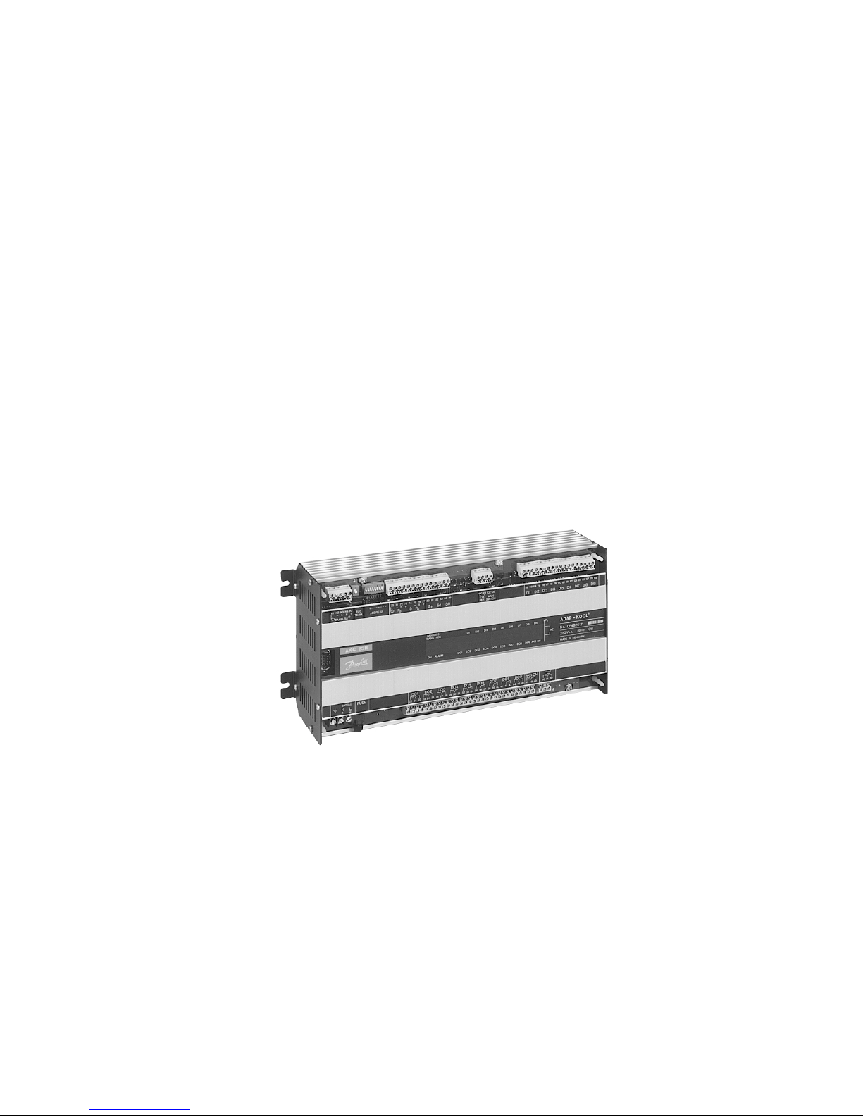
Compressor Pack Controller
AKC 25H1
ADAP-KOOL
®
Function description
Page 2

2 Function description RC.1J.Z4.02 © Danfoss 09/1999 AKC 25H1
Contents
Introduction............................................................................................................................... 3
Operation .................................................................................................................................. 4
System information ................................................................................................................. 4
Language .................................................................................................................................. 4
Capacity regulation of compressor........................................................................................ 5
Regulation...................................................................................................................... 5
External displacement of reference ...............................................................................5
Neutral zone and regulating band................................................................................. 6
Compressor definition .................................................................................................... 6
Time delays for cut ins and cut outs............................................................................... 6
Sequence for cut in and cut out of capacity ...................................................................7
Signal from the compressor's safety controls ................................................................ 7
Hourmeter ......................................................................................................................8
Temperature sensor ....................................................................................................... 8
Forced control of compressor capacity ..........................................................................8
Capacity regulation of condenser .......................................................................................... 9
Regulation...................................................................................................................... 9
Neutral zone and regulating band................................................................................. 9
Condenser definition ...................................................................................................... 9
Signal from the condenser's safety controls ................................................................ 10
Hourmeter ....................................................................................................................10
Forced control of condenser capacity.......................................................................... 10
Overriding ............................................................................................................................... 11
Monitoring ............................................................................................................... 12
Monitoring of maximum discharge gas temperature ........................................ 12
Monitoring of maximum discharge pressure .................................................... 1 2
Monitoring of minimum suction pressure......................................................... 13
Monitoring of suction gas superheat................................................................ 13
Monitoring of the different parts of the compressor's safety circuit..................1 4
Monitoring of other automatic controls ............................................................ 14
Supply voltage ........................................................................................................................15
Function switch ...................................................................................................................... 15
Clock function ........................................................................................................................ 15
Refrigerant..............................................................................................................................16
Service....................................................................................................................................17
System measurements/data ................................................................................................ 18
Alarms and messages .......................................................................................................... 19
Access codes ........................................................................................................................ 23
Supporting text .......................................................................................................................23
Installation considerations ................................................................................................... 23
List of literature ...................................................................................................................... 24
This function description was revised in September 1999 and applies to AKC 25H1 with code
numbers 084B2017 and 084B2018.
Validity
Page 3
AKC 25H1 Function description RC.1J.Z4.02 © Danfoss 09/1999 3
Introduction AKC 25H1 is a complete control unit for capacity regulation of compressors and condensers
in commercial refrigeration.
The controller can be used in combination with other controllers in the Danfoss ADAP-KOOL
®
refrigeration control system.
In addition to capacity regulation the controller can transmit signals to other controllers about
operating conditions, e.g. forced closing of expansion valves, alarm signals and alarm
messages.
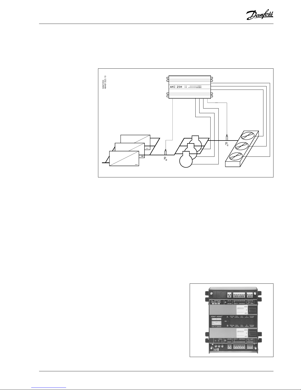
The controller’s main function is to control the compressors and condensers, so that they will
constantly operate at the optimum pressure conditions from an energy point of view. Both
suction pressure and condensing pressure will be controlled by signals from pressure
transmitters type AKS 32.
Among the various functions can briefly be mentioned:
- It can control a total of nine capacity steps distributed on compressor steps and condenser
steps, as required.
- There are nine digital imputs for monitoring the various automatic controls. The inputs can
be defined to monitor compressors, condensers or other ON/OFF signals, at your option. If
failure of a compressor is registered, the controller will control the capacity with the
remaining compressors.
- When the compressors stop, signals may be transmitted to the electronic expansion valves,
so that they close.
- LED’s on the front plate show the status of outputs and inputs.
- Alarm signals can be generated directly from the controller and via DANBUSS Data
Communication.
- Alarms are displayed with texts, so that it is easy to see the cause of the alarm.
The monitoring of a compressor’s safety
circuit may be extended from being a simple
type of monitoring to a more differentiated
monitoring of several parts of the safety
circuit. To achieve this, the controller must
be linked up with an alarm module type AKC
22H. This alarm module will then receive
signals from the different parts of the safety
circuit and will subsequently give an exact
report on the exact location of the problems
in the circuit.
Page 4

4 Function description RC.1J.Z4.02 © Danfoss 09/1999 AKC 25H1
Controller type AKC 25H1 is a unit in the ADAP-KOOL® refrigeration control system. The
controller can be linked up with other controllers in the system via a two-core connection - the
DANBUSS Data Communication. Through this connection information can be transmitted
between the units, like settings, measurements, alarms etc.
Remote service
The different messages and alarms can, via the telephone network, be transmitted by
modems to, say, a service company.
Address coding
An address code must be set by means of a number of switches on the controller’s front plate.
There are seven switches for the coding. How coding is performed is explained in the
installation instructions for the data communication cable (literature No. RC.0X.A).
Connection of control panel type AKA 21
A plug for the connection of control panel AKA 21 is mounted right on the front plate of AKC
25H1. (If the control panel is to be used in any other place, a terminal box will have to be
installed (cf. the installation instructions for the data communication cable, literature No.
RC.0X.A).)
Data communication
To obtain correct data communication it is important that the installation instructions for the
data communication cable be adhered to (literature No. RC.0X.A).
The controller can be operated in two different ways. Either by using control panel type AKA
21 or by means of a PC with system software type AKM.
AKA 21 operation
Setting of the different functions is performed via a menu system. The menu system is built up
on several levels where you change around between the different menus by means of arrow
keys.
The complete list of menus is contained in the document “Menu operation via AKA 21”. (Cf.
list of literature).
PC operation
Operation takes place from a PC where Microsoft-Windows and System Software type AKM
have been installed. (The PC is connected to the system via Gateway type AKA 243/244).
Setting of the different functions is performed by means of rolling menus and dialogue boxes.
Settings can either be made via the keyboard or by using a mouse.
For users of AKM system software the complete list of menus is found in the document “Menu
operation via AKM”. (Cf. list of literature).
There are three languages in the controller. Depending on the code number selected, the
languages are either: English, German and French or English, Danish and Spanish.
When the required language has been selected, the individual functions will be shown in this
language, both when there is operation via AKA 21 and system software type AKM.
NB! When you operate system software type AKM it is important that the language code is set
before an upload of the controller’s data is carried out to the AKM programme (it is the set
language that will be picked up by the AKM programme). Select one of the controller’s three
languages by means of the following settings:
0: English
1: German
2: French
3: Danish
4: Spanish
Activate the selected language by pushing "Enter" and then push "Clear".
Main Function Main Function Settings Language___
System information
Operation
Language
Page 5
AKC 25H1 Function description RC.1J.Z4.02 © Danfoss 09/1999 5
The step regulator in the controller can control up to nine capacity steps that can be
distributed on one, two or more compressors. (The controller has a total of nine relay outputs
that have to be distributed between compressor steps and condenser steps).
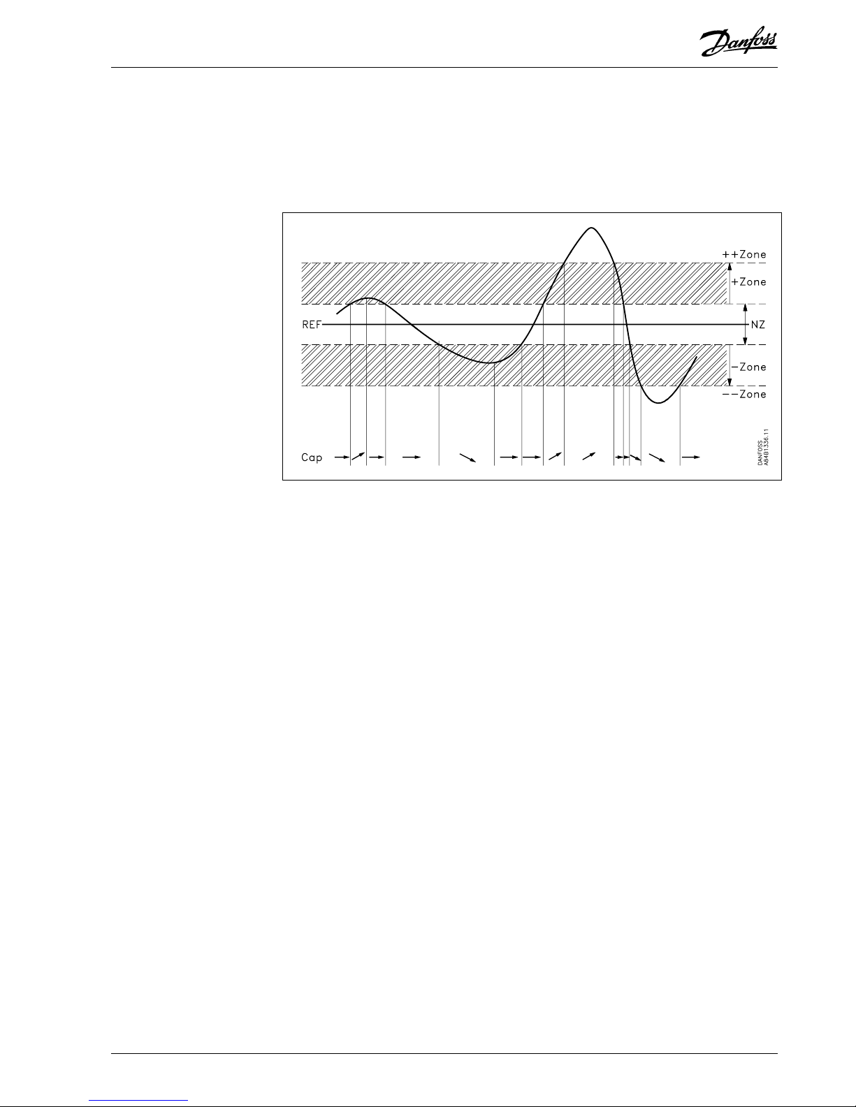
Regulation
The cut in compressor capacity is controlled by the actual value of the suction pressure and
whether the pressure is rising or falling.
- In the neutral zone there is no cut in/cut out of capacity steps.
- In the “+zone” and “-zone” bands cut in/cut out will depend on whether the pressure is rising
or falling. Cut in/cut out takes place with the selected time delays.
- In the “++zone” and “--zone” bands cut in/cut out takes place with the selected time delays.
- Refrigeration is stopped at pressures that are lower than the set “limit” value. (Cf. section on
“monitoring”).
Control reference
The regulation is based on the set value and the pressure measured by pressure transmitter
PO.
Compressor Capacity Ctrl. Settings Compressor Ctrl. P0 SP °C ___
External displacement of reference
The reference for the regulation can be displaced by means of two functions:
1. An external voltage signal transmitted to the “EXT.REF” terminal. The voltage must be 0-10 V.
With this signal the reference can be displaced by up to 50 K in positive or negative
direction. 10 V gives max. displacement.
The reference change is damped with a time constant of approx. 300 seconds.
Compressor Capacity Ctrl. Settings Compressor Ctrl. K1 Gain K ___
New reference = set reference + voltage signal x “K1 Gain K”/10
2. A night setback signal connected to terminal “S6”. The signal must short circuit the input.
With this signal the reference can be displaced by up to 25 K in positive or negative
direction. (Cf. also later section “Temperature sensor”).
The reference change is damped with a time constant of approx. 300 seconds.
Compressor Capacity Ctrl. Settings Compressor Ctrl. Night Ref. K ___
The “Forced Nght” signal can also be generated via a setting in the controller.
Compressor Capacity Ctrl. Settings Compressor Ctrl. Forced Nght OFF/ON ___
(This setting can also be made from a mastergateway’s override function).
New reference = set reference + voltage signal x “K1 Gain K”/10 + “Night Ref.K”.
Capacity regulation of
compressor
Page 6

6 Function description RC.1J.Z4.02 © Danfoss 09/1999 AKC 25H1
Neutral zone and regulating band
Neutral zone is set.
+zone and -zone bands are set.
Time delay in +zone and -zone band is set.
Time delay in ++zone and --zone band is set.
Compressor Capacity Ctrl. Settings Compressor Ctrl. NZ K ___
+Zone K ___
+Zone s ___
++Zone s ___
-Zone K ___
-Zone s ___
- -Zone s ___
Compressor definition
The controller can regulate up to nine compressor steps distributed on one, two or more
compressors. (If all nine steps are used for compressor control, there is no room left for the
control of condenser steps).
The controller is based on all the connected compressor steps being equally sized but this is
not a requirement.
The compressor steps must be defined in groups, so that the controller will know which steps
belong to compressor 1, which to compressor 2, etc. This definition is made by setting relay
outputs DO1 to DO9.
For each relay output you select the compressor that is to belong to it. If several are selected
with the same compressor number, it will be the relay with the lowest number that stops and
starts the compressor. The subsequent relays will control the individual unloaders.
Output Configuration DO Relay No. ( ) DO( ) Type = 1(1=compressor)
DO( ) Dev. No
Example:
A system consists of two compressors. One with three steps and one with two steps. The
definition here is performed, as follows:
Output Configuration DO Relay No. 1 DO1 Type = 1(1=compressor)*
DO1 Dev. No = 1
DO2 Type = 1(1=compressor)
DO2 Dev. No = 1
DO3 Type = 1(1=compressor)
DO3 Dev. No = 1
DO4 Type = 1(1=compressor)*
DO4 Dev. No = 2
DO5 Type = 1(1=compressor)
DO5 Dev. No = 2
The two relay outputs marked with a * will start and stop the compressors, and the others will
cut in and cut out the unloaders.
Time delays for cut ins and cut outs
To protect the compressor motor against frequent restarts, two time delays can be set.
- a minimum period which shall pass from a compressor starts till it can be restarted.
- a minimum period (on-time), during which the compressor must be operating, before it can be
stopped again (to avoid a cutout before the suction pressure has had time to become stable).
The setting ranges are from 0 to 25 minutes.
Output Configuration DO Relay No. ( ) DO( ) Recy m ___
DO( ) ON m ___
Page 7
AKC 25H1 Function description RC.1J.Z4.02 © Danfoss 09/1999 7
Sequence for cut in and cut out of capacity
The sequence for cut in and cut out of capacity can be defined in two ways. Either with a fixed
defined sequence or with automatic equalisation of run time between the connected
compressors. The sequence will be established by the following setting:
1. Sequential (Step Mode = 1).
In general the numbers with which the different compressors are defined will establish the
sequence for the cut ins (the compressor defined with a low number will start before a
compressor with the next number).
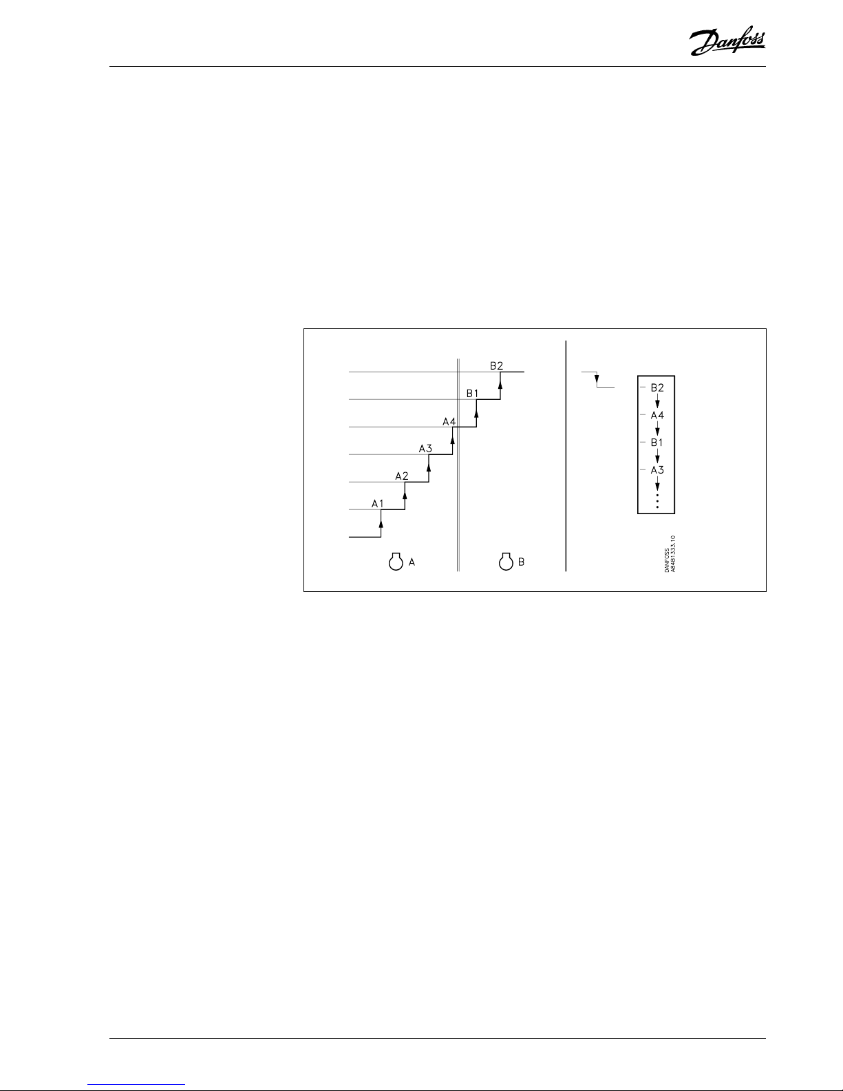
The sequence for the cut outs will furthermore be established by the compressor type:
Compressors with one step
The sequence is not changed (last cut in step will be cut out first, when the required
capacity drops again).
Compressors with several steps
When there are cut outs, the steps on the borderline between the two compressors will
be changed around. The function will produce the effect that the last started compressor
will not stop until the control has cut out the “last” step of the previous compressor.
Example:
Cut in Cut out
2. Automatic equalisation of run time between compressors (Step Mode = 2).
This setting should only be used if capacities of the same size are cut in or out but it is not a
requirement. (Regulation can also be carried out on compressors with several steps).
- At the different starts, the compressor with the lowest amount of run time will be started
first.
- At the different stops, the compressor with the highest amount of run time will be stopped
first.
- For compressors with several steps there will be no changes of the steps, as is the case
with sequential cut ins and cut outs.
Compressor Capacity Ctrl. Settings Compressor ctrl. Step Mode 1 / 2
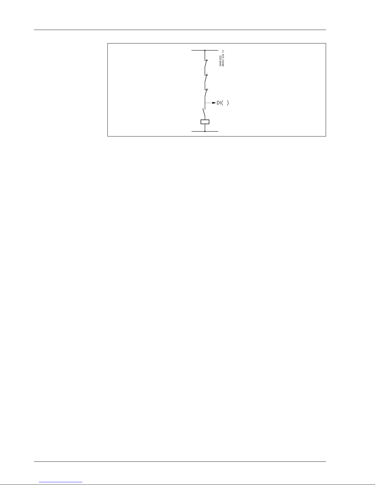
Signal from the compressor's safety controls
The controller requires a signal on the status of each compressor’s safety circuit. The signal
taken directly from the safety circuit is connected to a “DI” input. This input is a 230 V a.c.
input.
(The safety circuit must stop the compressor without the help of AKC 25H1).
If the safety circuit is broken, the controller will cut out all output relays for the compressor in
question and give an alarm. The other compressors will continue the regulation. (A broken
circuit at the DI input cuts out the outputs).
An input from a compressor and the compressor’s number are defined.
Input Configuration Alarm input No. 1..9 DI( ) Type = 1(1=compressor)
DI( ) Dev. No. ___ (compressor No.)
A time delay has to be defined in connection with all alarms. It covers the period of time from
the cut out moment until the alarm is registered.
Input Configuration Alarm input No. 1..9 DI( ) Del. m ___
Page 8
8 Function description RC.1J.Z4.02 © Danfoss 09/1999 AKC 25H1
The alarm message concerning a failure in the safety circuit can be extended into a more
concrete message by using alarm module type AKC 22H. Read the later section on
monitoring.
Hourmeter
The run time of a compressor motor is constantly registered. It can be shown on the display
how many hours the compressor has been operating since the hourmeter was last reset, and
how many starts there have been during the past 24 hours. (About resetting, see later).
Compressor Status Compressor No.( ) ( ) Run time
Compressor Status Compressor No.( ) ( ) Cut / 24 h
All relay outputs are registered by a counter. The run time is registered here for whatever has
been connected to the output. This registration can be shown on the display, and reset, if
required.
Output Configuration DO Relay No.( ) DO( ) Time h
The hourmeter range is from 0 to 30,000 hours.
Temperature sensor
The controller has an input, S6, for temperature measurement. The measurement has no
influence on any regulating functions. The input is, however, used for the night setback signal
when the regulation has to change between two different suction pressures. (A short circuited
input raises the suction pressure).
If data are to be logged from the input, it cannot at the same time be used as signal input for
the change between the two suction pressures.
The service function is used for displaying the temperature values.
Service Mode Measurements of input terminals S6 °C
Forced control of compressor capacity
There can be forced control of the capacity where the normal regulation and the safety
function are disregarded. The capacity is set in per cent of the regulated capacity.
Compressor Capacity ctrl. Settings Compressor ctrl Man. Cap OFF/ON
Man. Cap. % ___
Compressor control, but no condenser control
The controller is normally used for controlling both the compressor and the condenser. If the
controller is only used for controlling the compressor, a missing signal at the pressure
transmitter input Pc will trigger an alarm signal. To avoid this alarm, a signal can be picked up
from pressure transmitter PO. Connect terminal 72 to 76 (“s” to “s”). The monitoring function
for PCmax must be set at the highest possible value.
Page 9

AKC 25H1 Function description RC.1J.Z4.02 © Danfoss 09/1999 9
The step regulator in the controller can control up to nine capacity steps that may be
distributed on one or more condensers. (The controller has nine relay outputs that may be
distributed between compressor steps and condenser steps).
Regulation
The cut in condenser capacity is controlled by the actual value of the condensing pressure,
and on whether the pressure is rising or falling.
- In the neutral zone there is no cut in/cut out of capacity steps.
- In the “+zone” and “-zone” bands cut in/cut out depends on whether the pressure is rising or
falling.
Cut in/cut out takes place with the selected time delays.
- In the “++zone” and “--zone” bands cut in/cut out takes place with the selected time delays.
The regulation is based on the set value and the pressure measured by pressure transmitter
Pc.
Condenser Capacity Ctrl. Settings Condenser Ctrl. Pc SP °C ___
Neutral zone and regulating band
The neutral zone is set.
The +zone and -zone bands are set.
The time delay for the +zone and -zone bands is set.
The time delay for the ++zone and --zone bands is set.
Condenser Capacity Ctrl. Settings Condenser Ctrl. NZ K ___
+Zone K ___
+Zone s ___
++Zone s ___
-Zone K ___
-Zone s ___
- -Zone s ___
Condenser definition
The controller can control several condenser steps.
The condenser steps must be defined in a sequence so that the controller will know which
output belongs to condenser step 1, which output to condenser step 2, etc. The individual
condenser steps can control the same capacity and they will be cut in and out in sequence.
The steps defined with the lowest number will be cut in first, then the step defined with a
higher number, etc. Cut out takes place in the opposite sequence. Thus, the last cut in step
will be cut out first.
Output Configuration DO Relay No. ( ) DO( ) Type 2 (2=condenser)
DO( ) Dev. No
Capacity regulation of
condenser
Page 10

10 Function description RC.1J.Z4.02 © Danfoss 09/1999 AKC 25H1
Example:
A system consists of three condenser steps. Here the definition can be made, as follows:
Output Configuration DO Relay No. ( ) DO5 Ttype = 2 (2=condenser)
DO5 Dev. No = 2
DO6 Type = 2 (2=condenser)
DO6 Dev. No = 1
DO9 Type = 2 (2=condenser)
DO9 Dev. No = 3
Here the cut in and cut out sequence will be, as follows: 1, 2, 3 - 3, 2, 1.
I.e., the relay outputs will be activated in this sequence: DO6, DO5, DO9 - DO9, DO5, DO6.
Signal from the condenser's safety controls
The controller can receive signals on the status of each condenser step’s safety circuit. The
signal is taken directly from the safety circuit and is connected to a “DI” input.
This input is a 230 V a.c. input.
If the safety circuit is broken, the controller will cut out the output relay for the relevant step
and give an alarm. The remaining steps will continue the regulation. (A broken connection on
the DI input will cut out the output).
An input from a condenser step and the number of the condenser step are defined.
Input Configuration Alarm input No. 1..9 DI( ) Type = 2 (2= condenser)
DI( ) Dev. No. ___
A time delay must be defined for the period from the alarm is registered until it is transmitted.
Input Configuration Alarm input No. 1..9 DI( ) Del. m ___
Hourmeter
The run time of the different outputs is registered by a counter. This registration can be
displayed and reset, if required.
Output Configuration DO Relay No.( ) DO( ) Time h
The hourmeter’s range is from 0 to 30,000 hours.
Forced control of condenser capacity
Forced control of the capacity can be arranged, where the normal regulation is disregarded.
The capacity is set in per cent of the regulated capacity.
Condensor Capacity ctrl. Settings Condenser ctrl. Man. Cap OFF/ON
Man. Cap. % ___
Condenser control, but no compressor control
The controller is normally used for controlling both compressors and condensers. If the
controller is only used for controlling condensers, a missing signal from pressure transmitter
input PO will trigger an alarm signal. To avoid this alarm, a signal may be picked up from
pressure transmitter Pc. Connect terminal 72 to 76 (“s” to “s”). The monitoring function for
POmin is now set at the lowest possible value.
Page 11
AKC 25H1 Function description RC.1J.Z4.02 © Danfoss 09/1999 11
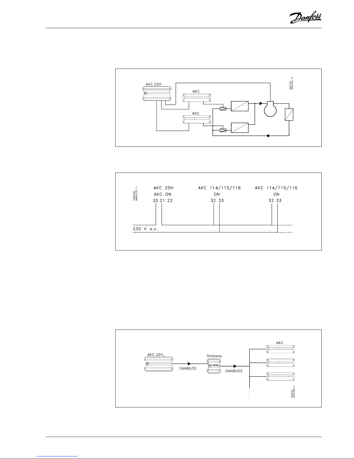
Overriding Forced closing signal to AKC 114, 115 and 116 controllers.
The electronic expansion valves must close, when all compressors are stopped. This is to
avoid the evaporators filling with liquid which is then passed on to a compressor when it starts
up again.
Either use the signal input “ON” on the AKC controllers.
When this signal is cut out, the controller will close the connected AKV valves.
During normal operation a 230 V signal must be transmitted to the AKC 114-116 controllers.
This signal must be supplied via the “AKC ON” relay switches. This relay is operated during
normal operation.
The “AKC ON” relay cuts out when all compressor steps are stopped.
E.g. when:
- the function switch “Main Sw.” on AKC 25H1 has been put in position 0
- the “Main Switch” input is broken.
- or during normal regulation when one of the monitoring functions has cut out the regulation.
Or the “ON” signal can be transmitted via the data communication.
The override signal can be obtained in another way than through the wirings shown, but only
if a gateway type AKA 243/244 has also been fitted in the system.
The “ON” signal is here sent via DANBUSS to the gateway which will then retransmit the
message about closing to the relevant controllers. Cf. the gateway manual and AKM’s
override function.
Page 12

12 Function description RC.1J.Z4.02 © Danfoss 09/1999 AKC 25H1
Monitoring of maximum discharge gas temperature
This function gradually cuts out compressor steps, if the discharge gas temperature becomes
higher than the permitted value. The cut out limit can be defined in the range between 0 and
+150°C.
The discharge gas temperature is measured with the temperature sensor on the Sd input (this
sensor should always be mounted).
The function starts with a value that is 10 K below the set value. At this point the entire
condenser capacity is cut in at the same time as half of the compressor capacity is cut out.
The alarm function is activated.
If the temperature rises to the set limit value, all compressor steps are immediately cut out,
and the function “AKC ON” is interrupted.
The alarm ceases when the temperature has dropped to the 10 K below the limit value for 60
seconds
Renewed cut in of the compressor step is allowed when the following conditions are
complied with:
- the temperature has dropped to the 10 K below the limit value
Safety functions Limits with 1.Priority Sd Max °C ___
Monitoring of maximum discharge pressure
The function cuts in all condenser steps and gradually cuts out compressor steps, if the
condensing pressure exceeds the permitted value. The cut out limit can be defined in the
range between -30 and +70°C.
The condensing pressure is measured with the pressure transmitter on the Pc input.
The function starts at a value that is 3 K below the set value. At this point the entire condenser
capacity is cut in at the same time as half of the compressor capacity is cut out. The alarm
function is activated.
If the temperature (pressure) rises to the set limit value, the following happens:
- all compressor steps are immediately cut out
- the condenser capacity remains cut in
- the function “AKC ON” is interrupted.
The alarm ceases again when the temperature (pressure) has dropped to the 3 K below the
limit value for 60 seconds.
Renewed cut in of compressor steps is allowed when the following conditions are complied
with:
- the temperature (pressure) has dropped to the 3 K below the limit value
Safety functions Limits with 1.Priority Pc Max °C ___
Monitoring
Page 13

AKC 25H1 Function description RC.1J.Z4.02 © Danfoss 09/1999 13
Monitoring of minimum suction pressure
The function immediately cuts out all compressor steps if the suction pressure becomes lower
than the permitted value. The cut out limit can be defined in the range between -100 and
+30°C.
The suction pressure is measured with the pressure transmitter on the PO input.
Cut outs activate:
- the alarm function and
- the function “AKC ON” is interrupted.
The alarm ceases when the following conditions are complied with:
- the pressure (temperature) is above the cut out limit
- the delay time has ecpired (see later)
Renewed cut in of compressor steps is allowed when the following conditions are complied
with:
- the alarm has stopped (the time delay has expired)
- the time delay prior to renewed cutin has expired
Safety functions Limits with 1.Priority P0 Min °C ___
Time delay
There is a common time delay period for the three earlier mentioned functions: Monitoring of
max. discharge temperature, max. discharge pressure, and min. suction pressure.
After a cut out, regulation cannot commence again until the time delay has expired.
The time delay starts when the temperature has again dropped to 10 K and 3 K, respectively,
below the limit value. Or when the pressure has risen above the P0min value.
The time delay can be defined in the range between 0 and 30 minutes.
Safety functions Limits with 1.Priority Restart m ___
Monitoring of suction gas superheat
The function monitors the superheat and gives an alarm, if the superheat becomes higher or
lower than the defined values.
Superheat is measured with the pressure transmitter on the PO input and the temperature
sensor on the Ss input.
Maximum superheat
The alarm limit can be defined in the range between 20 and +80 K.
Minimum superheat
The alarm limit can be defined in the range between 0 and +20 K.
Time delay
The alarm will not be sounded until the time delay has expired. The time delay can be defined
in the range between 0 and 60 minutes.
Safety functions Limits with 1.Priority SH Max K ___
SH Min K ___
SH Delay m ___
Page 14

14 Function description RC.1J.Z4.02 © Danfoss 09/1999 AKC 25H1
Monitoring of the different parts of the compressor's safety circuit
Instead of a simple monitoring of the safety circuit, this monitoring may be extended with an
alarm module, type AKC 22H. It will now be possible to deliver a definitive alarm message
telling you which part of the safety circuit has fallen out. The connection must be established
in this way:
The connections and the individual alarm messages are fixed and cannot be changed:
- Compr. No ( ) oil press. cut out (too low oil pressure)
- Compr. No ( ) current cut out (motor overload cut out)
- Compr. No ( ) motor prot. cut out (too high temperature in motor winding)
- Compr. No ( ) disch. temp. cut out (too high pressure gas temp.)
- Compr. No ( ) disch. press. cut out (too high discharge pressure)
- Compr. No ( ) safety cut out (signal missing from alarm module)
- Compr. No ( ) not in auto (switch in manual mode)
Carry out the settings mentioned in the earlier section “Signal from the safety controls”.
All alarm modules are double, i.e. one module can monitor two safety circuits. Each circuit is
connected to a DI input on AKC 25H1. Only inputs DI1 to DI8 can be used as inputs from an
alarm module. DI9 is only for monitoring of other automatic controls.
Monitoring of other automatic controls
The controller is provided with nine digital inputs. Some of the inputs are used for information
pertaining to the status of the safety circuits for the individual compressors, others for the
individual condenser steps. The remaining inputs may be used for other purposes to the
required extent. If an input is used for another purpose, an alarm text can be defined which is
transmitted when the input is broken. The following alarm texts can be defined:
Input Configuration Alarm input No. 1..9 DI( ) Type = 3 (3 = Other automatic)
DI( ) Dev. No. ___ 1: Low liquid level
2: Refrigerant leak
3: Current fault
4: Phase fault
5: Liquid flow switch
6: Air flow switch
7: Flow pump fault
8: Condensate pump fault
9: High codensate level
Time delays are defined for the individual alarm inputs.
Input Configuration Alarm input No. 1..9 DI( ) Del. m ___
Page 15

AKC 25H1 Function description RC.1J.Z4.02 © Danfoss 09/1999 15
The controller must be supplied with 230 V a.c., with live connected to terminal No. 2. It is a
requirement that the controller has earth connection. It is installed at the terminal next to the
mains connection.
A 1 A slow-blowing Ø5 x 20 mm fuse should be mounted in series with the live.
The controller has been factory-set at a network frequency of 50 Hz. If the supply is 60 Hz, the
setting must be changed to this value.
Main function Main switch Mains freq ____
The controller has two functions that can start and stop the regulation. A function switch inside
the unit that can be set via the control function and an external input that can be connected to
a switch.
Internal
The switch has three positions:
- Normal regulation (setting = +1)
- Regulation stopped (setting = 0)
- Service function. (setting = -1)
Main function Main switch Main switch +1/0/-1
If the switch is set in pos. 0 or -1, all the controller’s functions are inactive. An alarm with the
text “Standby mode” is generated to indicate that regulation has stopped. If the switch is in
pos. +1, regulation has begun for the functions selected with “ON”.
External
If the external function switch is used, a switch for the “Main Switch” input must be connected.
If it is not used, the input must be shortcircuited. There are two menu groups that only can
be set when the MAIN SWITCH input is interrupted. The two groups are the following:
“Input Configuration” and “Output Configuration”.
The combination of internal and external switch is, as follows:
- Regulation is only carried out when both switches are in pos. ON (internal = +1 and external
= shortcircuited).
- Service settings can be made when the internal switch is put in pos. “Service Function”
(setting = -1) External = shortcircuited.
- All other combinations will stop the regulation.
The controller contains a clock function. Setting of days, hours and minutes can be performed
here.
AKC 25H1 Adr: -- Clock: day: 1-7 (1=Monday, 7=Sunday)
AKC 25H1 Adr: -- Clock: hour: 0-23
AKC 25H1 Adr: -- Clock: min: 0-59
Note:
If the controller is connected to an installation with gateway, type AKA 243/244, the gateway
will reset the clock function after a power failure.
Supply voltage
Function switch
(Main Switch)
Sensor failure
If a missing signal from one of the connected temperature sensors or pressure transmitters is
registered, an alarm will be given. If it is PO (the pressure transmitter for the suction pressure)
that fails, the refrigeration will immediately be stopped. If it is the Pc unit (the pressure
transmitter for the condensing pressure) that fails, the whole condenser capacity will be cut in.
Clock function
Page 16

16 Function description RC.1J.Z4.02 © Danfoss 09/1999 AKC 25H1
Before regulation can be commenced, the refrigerant must be defined.
You may select one of the following refrigerants:
1 R12 9 R500 17 R507
2 R22 10 R503 18 R402A
3 R134a 11 R114 19 R404A
4 R502 12 R142b 20 R407C
5 R717 (ammonia) 13 User-defined 2 1 R40 7A
6 R13 14 R32 22 R407B
7 R13b1 15 R227 23 R410A
8 R23 16 R401A
The refrigerant is selected by keying a figure between 1 and 23. If you push 0, no refrigerant
has been selected.
Warning: Incorrect selction of refrigerant can cause damage to the compressor.
Main function Rfg. type 1..23 Rfg. type ___
Rfg. Fac. a1 ___
Rfg. Fac. a2 ___
Rfg. Fac. a3 ___
A subsequent change of refrigerant can only be performed in this way:
- Select new type
- The controller reports an error
- Interrupt supply voltage to the controller
- Wait five seconds
- Reconnect supply voltage
- Regulation can be started again
Other refrigerants?
The function has been prepared for the definition of a refrigerant that differs from the above
mentioned types. This definition can be made by keying the figure “13” plus a number of
subsequent parameters. This setting can only be made with assistance from Danfoss.
Refrigerant
Page 17

AKC 25H1 Function description RC.1J.Z4.02 © Danfoss 09/1999 17
The function is used in connection with installation, service and trouble-shooting on the
system. With this function, the connected functions can be checked, fx. temperature sensors,
pressure transmitters, ON/OFF inputs and alarm function.
Measurements
The following functions can be read and checked here:
- sensor values
- signal value on the “Ext.Ref.” input
- status of “Ext.Main” input
- status of input signals
- status of output signals
Service mode Measurements of input terminals P0 Bar
Pc Bar
Ss °C
Sd °C
S6 °C
Ext. Ref. V
Ext. Main
DI1....9
Measurements of output terminals DO1 Relay ...... DO9 Relay
AKC ON
Alarm Relay
Forced control of outputs
Components connected to the controller’s outputs can be forced control.
NB! There is no monitoring when the outputs are subject to forced control.
Man. Ctrl. (access requirements)
To use this service function, two settings have to be made:
1. The function switch is put in pos. Service
Main function Main Function Settings Main switch = -1
(This will trigger an alarm message “Standby mode” to indicate that regulation has
stopped, and that all outputs are in pos. OFF).
2. “Manual control” is put in pos. ON
Service Mode Manual control output Man. ctrl = ON
(Service function is activated).
The individual outputs can now be controlled by force.
DO1 Relay
ON/OFF setting of relay outputs DO1...DO9
If a compressor with unloaders has been connected, one of the outputs will control the
compressor while the remaining relays will control the unloaders.
Service Mode Manual control output DO( ) Relay: OFF/ON
AKC ON
ON/OFF setting of relay output “AKC ON”
(The function stops the regulation in all connected AKC 114, 115 and 116 controllers).
Only the relay output is force-controlled. No signal is transmitted to the DANBUSS.
Service Mode Manual control output AKC ON: OFF/ON
Alarm Relay
ON/OFF setting of alarm output
OFF activates the alarm (interrupted output = active alarm).
Service Mode Manual control output AlarmRelay: OFF/ON
When operation with forced control is terminated (the service function is abandoned and the
setting of the function switch is changed (Main Switch = 0 or 1), “Man. ctrl.” will automatically be
put in pos. OFF. At the same time the settings of the outputs will change back to the factory-set
values.
Service
Page 18

18 Function description RC.1J.Z4.02 © Danfoss 09/1999 AKC 25H1
System measurements/
data
Functions and measurements pertaining to the refrigerating system can be shown on the
control panel’s display or on the PC screen by system software type AKM.
Displayed temperatures are indicated in °C or K, and functions with ON or OFF.
AKA 21 operation
A display with ***** indicates that there is a defective sensor or that a sensor has not been
mounted.
Compressor regulation
P0 °C Actual suction pressure in °C
P0 Ref °C Suction pressure reference
Comp. Cap.% Actual cut in compressor capacity
Req. Cap. % Compressor capacity reference
Pc °C Actual discharge pressure in °C
Sd °C Actual discharge temperature
SH K Actual superheat
Night s.b. Status of night-setback function (ON or OFF)
( ) Cap. % Actual cut in capacity for this compressor (()=1-9)
( ) Run time Compressor’s accumulated run time in hours (()=1-9)
( ) Cut / 24 h Compressor’s number of starts the past 24 hours
Condenser regulation
Pc °C Actual discharge pressure in °C
Pc Ref. °C Discharge pressure reference in °C
Cond. Cap. % Actual cut in condenser capacity
Req. Cap. % Condenser capacity reference
Controller data
Code no. Controller’s code number and software version
System address Controller’s system address (set from a PC)
Address Controller address (set on the controller’s switches)
Alarm report to System address (end receiver) to whom alarms are to be sent
(set from a PC)
Gateway address Address of nearest gateway that is to transmit alarms
(set from a PC)
Constant updating
If constant display of a menu is required, e.g. a temperature value, the display on the control
panel can be locked to the menu.
Procedure: Show the required menu on the display, push the ENTER key for three seconds.
The function is cancelled by pushing one of the arrow keys.
PC operation
In addition to the earlier described measurements with control panel type AKA 21 it is with
operation from a PC, also possible to define the importance of the various alarms. Read the
section: “Alarms and messages”.
Page 19

AKC 25H1 Function description RC.1J.Z4.02 © Danfoss 09/1999 19
In connection with the controller’s functions there are a number of alarms and messages
which become visible in case of a fault or incorrect operation.
Distinction is made between important information and not so important information. The
degree of importance is fixed for some, whilst others can be changed if required. (This
change can only be made when a PC is connected to the system and settings have to be
made in each of the relevant controllers).
The importance is indicated by means of the following:
1. "Alarms"
This is important information from the controller.
- The controller’s alarm output is activated.
- Information is transmitted on the DANBUSS network together with status value 1.
- If a gateway type AKA 243/244 is connected and it is defined as master, its relay output
DO2 will be activated for two minutes.
- Later, when the alarm is discontinued, the same information will be repeated, but this time
with status value 0.
2. "Messages"
This is less important information from the controller.
- The information is transmitted on the DANBUSS
network together with status value 2.
- Later, when the “message” is discontinued, the same information will be repeated but this
time with status value 0.
0. “Suppressed information”
This information stops at the controller. It is not transmitted anywhere.
List of alarm activities
mralA
ecnatropmi
mralA
sutats
1H52CKA
yalermrala
1H52CKA
DELmrala
12AKA
DEL
442/342AKA
yaler2OD
1
mralAFFOSEHSALFSEHSALF.nim2FFO
mralaoNNOFFOFFONO
2
mralANOSEHSALFSEHSALFNO
mralaoNNOFFOFFONO
0
mralANOFFOFFONO
mralaoNNOFFOFFONO
Information from the controller
Below, the information is shown together with the importance of it. The information is shown in
brackets “[ ]”. If there are several figures in the bracket, the setting can be changed (the
factory setting is shown in bold type).
Standby mode [ 1, 2, 0 ]
Regulation can be stopped manually with the “Main Switch” menu, or by means of the
external input MAIN SWITCH.
When the regulation has been stopped, there will in addition to this message, only be
transmitted alarms for sensor faults. All other alarms and messages will be
suppressed.
RFG. type not selected [ 1,
2, 0 ]
No refrigerant has been selected.
Before regulation can be started, a refrigerant type will have to be selected.
RFG. type change after power up [ 1,
2, 0 ]
Refrigerant type changed after the controller was started.
Warning!! Change of refrigerant type can cause damage to the compressor. Cf.
section on selection of refrigerant.
Alarms and
messages
Page 20

20 Function description RC.1J.Z4.02 © Danfoss 09/1999 AKC 25H1
Manual capacity control set ON [ 1, 2, 0 ]
Capacity regulation inactive and the capacity is set by the forced control function for
compressor capacity or condenser capacity.
Suction temp. too low [ 1, 2, 0 ]
The suction pressure is too low.
The compressor has stopped. Wait for an increase of the pressure.
Discharge press. too high [ 1, 2, 0 ]
The discharge pressure is too high.
The compressor has stopped. Wait for a temperature drop.
Discharge temp. too high [ 1, 2, 0 ]
The discharge gas temperature is too high.
The compressor has stopped. Wait for a temperature drop.
Suction gas SH too high [ 1,
2, 0 ]
The superheat is too high.
Check the injection function.
Suction gas SH too low [ 1,
2, 0 ]
The superheat is too low.
Check the injection function.
Px Error [ 1 ]
Pressure transmitter interrupted, shortcircuited or not mounted. In case of an error the
controller will stop the belonging regulation and cut out the group of capacity steps.
Sx Error [ 1 ]
Sensor interrupted, shortcircuited, or not mounted.
Check the sensor.
No DI defined for compressor [ 1,
2, 0 ]
A compressor is defined but not a "DI input" to the compressor. If not wanted the
importance must be set to "0".
Page 21

AKC 25H1 Function description RC.1J.Z4.02 © Danfoss 09/1999 21
The following messages can be connected to a “DI input” at your option. This is done with the
“configuration of inputs” setting.
For each individual DI input you may furthermore define the importance of the alarm:
DI( ) Dest [ 1,
2, 0 ]
Air flow switch Error report from the air flow switch.
Check the flow switch.
Compr. no( ) current cut out Alarm from AKC 22H.
Check the alarm input on AKC 22H.
Compr. no( ) disch temp cut out Alarm from AKC 22H.
Check the alarm input on AKC 22H.
Comp. no( ) disch press. cut out Alarm from AKC 22H.
Check alarm input on AKC 22H.
Compr. no( ) motor prot. cut out Alarm from AKC 22H.
Check alarm input on AKC 22H.
Compr. no( ) not in auto Wrong setting of switch on alarm module
AKC 22H. Put switch in pos. “AUT”.
Comp. no( ) safety cut out Signal on input DI( ) interrupted.
Check the compressor’s safety circuit.
Comp. no( ) oil press. cut out Alarm from AKC 22H.
Check alarm input on AKC 22H.
Cond. no( ) safety cut out Signal on input DI( ) interrupted.
Check the condenser’s safety circuit.
Condensate pump fault Drip tray pump defective.
Check the pump.
Current fault Faulty supply voltage.
Check the earth-leakage circuit breaker.
Flow pump fault Fault in the refrigerant circulation.
Check the refrigerant pump.
High condensate level Drip tray level too high.
Check the drip tray.
Liquid flow switch Error report from the liquid flow switch.
Check the flow switch.
Low liquid level Low refrigerant level.
Check the amount of refrigerant.
Phase fault Faulty supply voltage.
Check the supply voltage.
Refrigerant leak Refrigerant is leaking.
Check the unit that monitors leakage of
refrigerant.
This is how the various messages are transmitted:
Information is in principle sent twice.
1) An alarm message when the error is discovered.
2) A message about cancellation of the alarm situation, when the error disappears again.
(In connection with a sensor alarm, there may be 10 minutes between the two messages).
This procedure has a different influence on the below-mentioned systems:
Single systems (systems with control panel type AKA 21)
Information can be shown on the screen, when an “E” (error) is observed.
The error message cannot be removed from AKA 21, as long as the cause of the error
has not been removed. When the cause of the error message has been removed, the
error message will remain visible in AKA 21 until it is acknowledged by pushing
“Enter”.
Page 22

22 Function description RC.1J.Z4.02 © Danfoss 09/1999 AKC 25H1
Network (Systems with PC or AKA 243/244 with printer and control panel type AKA 21)
Here the information can be transmitted to the PC or the printer. Accompanying this
message is indication whether it is a new error or an earlier error that has been
transmitted. On control panel type AKA 21 only “new” alarms can be seen in this
situation. Old errors that are transmitted cannot be seen.
To use this function, you have to make a setting in the controller. This setting can only
be made from a PC.
The "Auto reset" setting is put in position "ON".
The individual messages will now be sent to the printer or the PC along with a status
which is either 1, 2 or 0.
1 means that it is new and important information (information defined with setting = 1)
2 means that it is new, but not quite so important information (information defined with
setting = 2)
0 means that the error has been deleted.
Who are the alarm receivers?
Single systems
Control panel type AKA 21 will here be the receiver of alarms from the connected
units.
- Each controller is given an address, so that the unit is defined in the system. Setting
of the address is performed directly in each controller via a number of switches (cf.
instructions).
Network systems
A defined PC or AKA 243/244 with printer will here be the receiver of alarms for the
connected units.
- Each controller is given an address, so that the unit is defined in the system. Setting
of the address is performed via a number of switches (cf. instructions).
- Each controller is given a system address. A system address consists of a network
number and an address (the address is the same as the one set in in the controller).
The network number must be set via the PC.
- The addresses of the receivers of all alarms must be set on each controller. There are
two kinds of settings which can only be carried out via the PC.
• The system address of the nearest gateway type AKA 243/244 which has to
retransmit alarms and messages.
• The system address of the final receiver of alarms and messages.
Alarm output on AKC 25H1
The output will only be activated when the setting is [1] (see above). Activation takes
place as long as the error is active.
The output is a “change-over function” to which the following applies:
No alarm: Terminals 50 and 51 are short circuited.
Alarm: Terminals 51 and 52 are short circuited.
Page 23

AKC 25H1 Function description RC.1J.Z4.02 © Danfoss 09/1999 23
The controller can be operated with system software type AKM and control panel type AKA 21.
Both operating modes may give access to several levels, depending on the user’s knowledge
of the various functions.
System software type AKM:
The different users are defined here with initials and passwords. Access is now granted to
exactly the functions the user is allowed to operate.
The operation is described in the AKM manual.
Control panel type AKA 21:
Access can be given to three user levels here:
1) Access without use of password.
See alarms. Display selected temperatures. Change temperature in the refrigeration
appliance. Start defrost.
2) Access via code 1
Setting of selected functions, acknowledgement of alarms.
3) Access via code 2
All settings in the menu system can be performed.
The operation is described in “Menu operation via AKA 21”.
If access code is set in pos. “0” (factory setting), there is free access to the system without the
use of a password.
AKC 25H1 Adr: --. Chg. Code1 ___
Chg. Code 2 ___
Access codes
When the controller is set from control panel type AKA 21, it is possible to show auxiliary texts
in the display for a few functions.
This is done by pushing the key “Help” when the required function is shown in the display. A
brief text will now appear which describes the setting. For example:
Function is shown Push "Help" Auxiliary line 1 appears
Push "↓" Auxiliary line 2 appears
etc.
Finish by pushing "←", and you will return to the function.
In the menu is shown which functions are provided with auxiliary texts.
Supporting text
Accidental damage, poor installation, or site conditions, can give rise to malfunctions of the
control system, and ultimately lead to a plant breakdown.
Every possible safeguard is incorporated into our products to prevent this. However, a wrong
installation, for example, could still present problems. Electronic control is no substitute for
normal, good engineering practice.
Danfoss wil not be responsible for any goods, or plant components, damaged as a result of
the above defects. It is the installer's responsibility to check the installation thoroughly, and to
fit the necessary safety devices.
Particular attention is drawn to the need for a “force closing” signal to controllers in the event of
compressor stoppage, and to the requirement for suction line accumulators.
Your local Danfoss agent will be pleased to assist with further advice, etc.
Installation considerations
Page 24

24 Function description RC.1J.Z4.02 © Danfoss 09/1999 AKC 25H1
List of literature
Technical brochure AKC 25H1, AKC 25H3 and AKC 25H5 ........................................ RC.1J.4
Catalogue. Pressure transmitters type AKS 32............................................................ RK.00.H
Catalogue. Temperature sensors ................................................................................ RK.00.H
Function description AKC 25H1 (this document)......................................................... RC.1J.Z
Function description AKC 25H5................................................................................... RC.1J.5
Installation guide for Data communication cable ......................................................... RC.0X.A
Mounting instructions AKC 25H1 (bypacked unit) ....................................................... RI.1J.T
Mounting instructions AKC 25H5 (bypacked unit) ....................................................... RI.1J.Z
Mounting instructions AKC 22H (bypacked unit) ......................................................... RI.1J.U
Menu operation via AKA 21, AKC 25H1 (software-based).......................................... RC.1J.X
Menu operation via AKA 21, AKC 25H5 (software-based).......................................... RC.1J.2
Menu operation via AKM, AKC 25H1 (software-based) .............................................. RC.1J.V
Menu operation via AKM, AKC 25H5 (software-based) .............................................. RC.1J.3
Table for entry of menu settings AKC 25H1 (bypacked unit)....................................... RI.1J.V
Table for entry of menu settings AKC 25H1 (bypacked unit)....................................... RI.1J.3
Table for entry of menu settings AKC 25H5 (bypacked unit)....................................... RI.1J.0
Table for entry of menu settings AKC 25H5 (bypacked unit)....................................... RI.1J.1
Danfoss can accept no responsibility for possible errors in catalogues, brochures and other printed material. Danfoss reserves the right to alter its products without notice. This also applies to products
already on order provided that such alternations can be made without subsequential changes being necessary in specifications already agreed.
All trademarks in this material are property of the respecitve companies. Danfoss and Danfoss logotype are trademarks of Danfoss A/S. All rights reserved.
AC-RDT
 Loading...