

Page 1
REFRIGERATION AND
AIR CONDITIONING
Gateway
AKA 245
Manual
Page 2

Validity
This manual is from August 2004, and applies to AKA 245 with software version 6.0x.
Contents
System survey ......................................................................................................................................3
Technical data ......................................................................................................................................4
Connections ............................................................................................................................................................... 4
Data ............................................................................................................................................................................... 5
Dimensions ................................................................................................................................................................. 5
Mounting .................................................................................................................................................................... 5
Function overview ...................................................................................................................................................6
Ordering ...................................................................................................................................................................... 6
Connections ......................................................................................................................................... 7
DANBUSS .................................................................................................................................................................... 7
LON ................................................................................................................................................................................8
DI1, DI2, DO1 and DO2 ........................................................................................................................................... 8
Printer ...........................................................................................................................................................................8
Manual change-over of alarm routing .............................................................................................................9
Alarm relay ..................................................................................................................................................................9
Battery .......................................................................................................................................................................... 9
PC, Modem or Server connection ....................................................................................................................10
Functional description ...................................................................................................................... 12
Network information ............................................................................................................................................12
Communication control ......................................................................................................................................13
Clock function .........................................................................................................................................................13
Automatic setup of controller alarm function .............................................................................................13
Alarm handling .......................................................................................................................................................13
AKA Alarm Table .....................................................................................................................................................16
Printer function .......................................................................................................................................................17
Data collection in master gate way .................................................................................................................18
Modem connection ...............................................................................................................................................19
TCP/IP server connection ....................................................................................................................................19
AKA override function ..........................................................................................................................................20
Operation ...........................................................................................................................................22
Principle .....................................................................................................................................................................22
Operation via AKA 21 ...........................................................................................................................................22
Operation via system software type AKM .....................................................................................................23
Access limitation ....................................................................................................................................................23
Password function .................................................................................................................................................23
Printer function .......................................................................................................................................................23
Settings .............................................................................................................................................. 24
General .......................................................................................................................................................................24
GATEWAY, Code. Access display and access code ........................................................25
Time setting. Clock function .........................................................................................26
Confi guration. Access codes and display ....................................................................27
Address & GWtype Address and gateway type .................................................................28
Communication setup. Setup of communication .....................................................................29
Appendix ........................................................................................................................................... 33
Routing ......................................................................................................................................................................33
Repeat routines for alarm handling ................................................................................................................37
Data collection takes up this much room .....................................................................................................38
Terminology .............................................................................................................................................................39
Menu survey AKA 245 ..........................................................................................................................................40
2 Manual RS8DT102 © Danfoss 09/2004 AKA 245
Page 3

System survey
Gateway types AKA 245 is a system component to be used in conjunction with controllers in the
ADAP-KOOL® series of controls for refrigerating systems.
When the gateway is used it is possible to build complex control systems with alarm moni toring and
data logging into decentralised refrigerating plant.
All controllers in the AKC series are linked up in a two-core data communication system that is
registered under the name DANBUSS Data Communication System.
A Gateway is the control unit used when the data communication system has to be connected to a PC,
a printer, a TCP/IP server or a modem.
Principle
Operation of gateway and the controllers in ADAP-KOOL®
refrigerating systems is performed with control panel type AKA 21
or with system software type AKM (installed on PC).
The control panel is connected to the two-core data
communication cable at any random point. After that, all settings
and adjustments pertaining to the day-to-day operation of the
system can be made.
Cold rooms and refrigeration appliances are regulated by AKC 72A
and AKC 114-116.
A gateway type AKA 245 is attached to the data communication
system and connected to a modem or printer.
If a PC is to be used in the actual system, one more gateway will
have to be connected. This gateway may also be an AKA 245, but
if the gateway is required for simple operation of the system, the
smaller type AKA 241 may be employed.
The printer can make printouts of all alarm reports registered on
the refrigeration system by the AKC controllers.
If the alarms are to be transferred to the security centre or to the
refrigeration company’s PC or printer, it must take place via the
modem connection.
Log data can be collected from all connected controllers. This data
may then be picked up by a PC and displayed.
Log data can also be stored as documentation for correct temperature behaviour (demands to temperature registration on the part
of the authorities).
It is also possible to communicate with other control lers via the LonWorks output. Primarily controllers
from the EKC 201, 300, 400, 500 or AK 2 series.
Example
Example
AKA 245 Manual RS8DT102 © Danfoss 09/2004 3
Page 4
Technical data
AKA 21
When mounted, AKA 21 is connected for setting of address, etc.
DANBUSS
Here there is a DANBUSS connection from one of the other units in the system.
The connections are described in a separate document bearing literature number RC0XA---
LON
Here the data communication is connected to controllers with a LONWORKS
®
- RS 485 interface (eg
EKC 201, 300, 400, 500 or AK 2 controllers). The connection is described in a separate document bearing literature number RC8AC---
Number of controllers
Up to 120 controllers distributed on DANBUSS and LON can be connected. Part of the range must be
assigned to the LON bus. The remaining part is used by the DANBUSS.
RS 232 / PC / TCP/IP
Used for connection of a PC, a modem or a TCP/IP server. Only one of these can be connected. Which
one can be defi ned with a setting in the gateway.
Printer
A printer is connected here.
Only printers with parallel interface can be used.
The two relay outputs DO1 and DO2 and the two inputs DI1 and DI2 have in this manual been described
with the most frequently used function. If you wish to use an input or an output diff erently, it must be given
a new confi guration. For this purpose system software type AKM must be used. Cf. the AKM manual.
Relay outputs (D01, D02)
The DO1 output is used with modem connection or TCP/IP connection. Via the relay output,
supply voltage is connected to the modem or TCP/IP connection. The DO2 output can be used for
transmitting a joint alarm signal to external equip ment. (DO2 is activated for two minutes when the
alarm handler in the master gateway (address 125) receives an alarm message of status 1 from a
controller).
When you use the alarm routing function it is possible to select D02 active or inactive within specifi ed
periods of time (cf. section “AKA Alarm Table”).
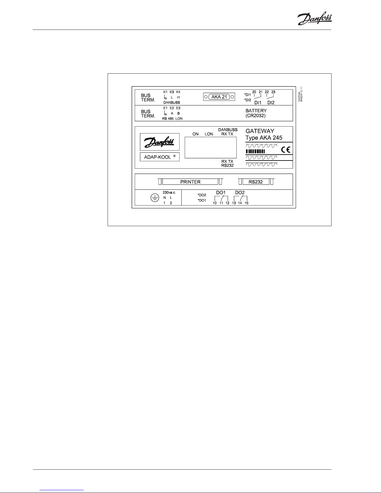
Connections
AKA 245
4 Manual RS8DT102 © Danfoss 09/2004 AKA 245
Page 5
Data
On/off inputs (DI1, DI2)
Input DI1 is used for the printer’s paper function. DI1 is connected to a contact function which is
operated when the paper has been placed in the printer. (Top of form setting).
The DI2 input is used for manual change-over between “default” and “optional” alarm destinations in
connection with the extended alarm routing (cf. section “AKA Alarm Table”).
Light-emitting diodes
- For each communication gate (RS 232/DANBUSS) there are two light-emitting diodes (LED), one
for sending and one for receiving. The diodes are lit, when there is communication to or from the
gateway.
- The status of the ON/OFF inputs and relay-outputs are also indicated with light-emitting diodes.
- There is an LED for power ON
- There is a LED for LON-communication
AKA 245
Supply voltage 230 V a.c. -15/+10% 50/60 Hz
Power consumption 4 VA
Relay outputs Max.contact load 1 A / 230 V ohmic
Digital inputs Off -cycle voltage >12 V d.c.
Short-circuit current >15 mA, <50 mA
Changeover level off : < 2 V
Changeover level ON: > 6 V
Ambient temperature During operation 0 to +55°C
During transport -40 to +70°C
Humidity 10 to 90% RH
Enclosure IP 00
Immunity EN 50082-1 Normative requirements
Radiation EN 50081-1 Normative requirements
Protection of data in the event of a
power failure
RAM Backup for approx.1 year
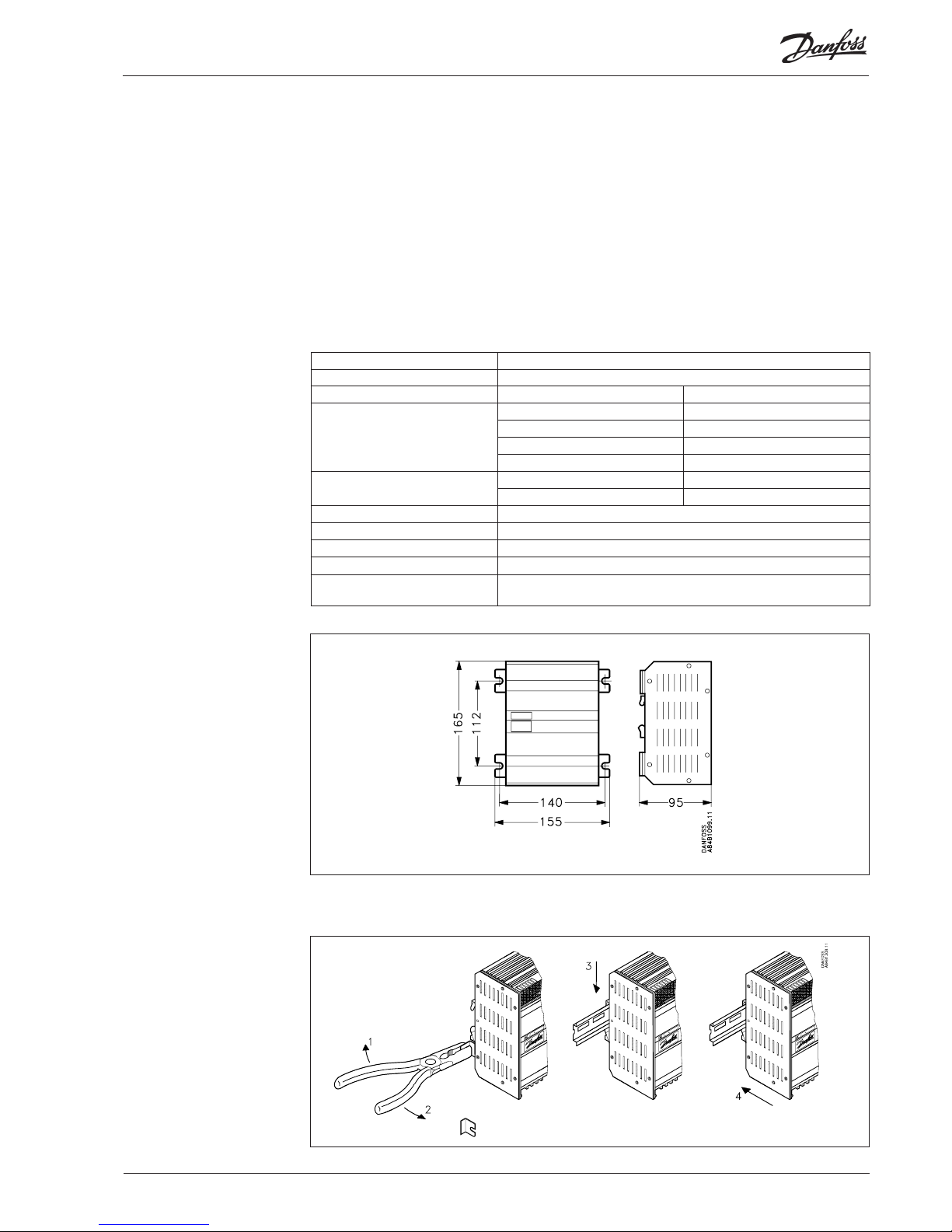
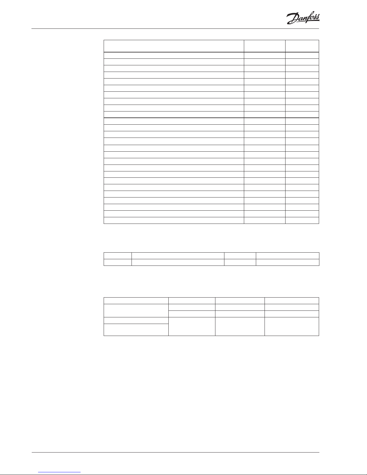
Mounting
The housing can be screwed into place by means of the screw brackets, or it may be mounted on a DIN
rail. When the housing is mounted on a DIN rail, the screw brackets must be broken off .
Dimension
AKA 245 Manual RS8DT102 © Danfoss 09/2004 5
Page 6
Cables
(see fi g. page 10 and 11)
Ordering
Functions overview
Type Specifi cation Number Code no.
AKA 245 Gateway 1 only 084B2268
Connection between Plug Length Code no.
PC and Gateway
9 pol - 9 pol 3 m 084B2094
9 pol - 25 pol 3 m 084B2096
PC and Lantronix MSS
9 pol - 25 pol 3 m 084B2098
Lantronix MSS server and
Gateway
Connection/function Gateway
type AKA 245
More details
on page
Connection:
PC x10
Modem x 11
TCP/IP server x 11
DANBUSS x 7
LON RS 485 x 8
Printer x8
Battery backup x 9
AKA 21 x7
Funcion:
Communication control x 13
Clock function x 13
Automatic setup of controllers alarm function
x13
Alarm handling x 13
Alarm recipient x 14
Alarm list x 15
Alarm status x 15
AKA Alarm table x 16
Printer function x 17
Data colleciton x 18
PC, Modem or TCP/IP connection x 19
AKA override function x 20
Operation via system software type AKM / AK Monitor x 23
Access limitation x 23
Password function x 23
6 Manual RS8DT102 © Danfoss 09/2004 AKA 245
Page 7
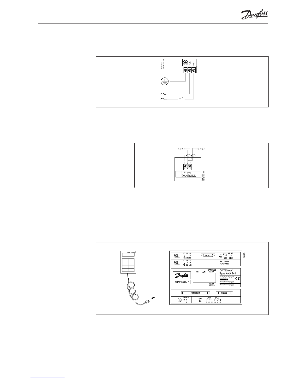
AKA 245 must always be provided with earth connection. This is to guarantee safety for persons and noise
immunity.
Data communication cable
Terminals
No.
K4 H
K3 L
K1 Screen
In general, the data communication is connected from controller to controller, so that L is connected
to L, and H is connected to H. The cable must be twisted in pairs and with screen.
NOTE
As regards installation of the data communication cable, reference is made to our special literature, No.
RC.0X.A.
Connections
Supply voltage
230 V a.c.
Max. fuse 10 A
Connection of control panel
DANBUSS
AKA 245 Manual RS8DT102 © Danfoss 09/2004 7
Page 8

DI1, DI2, DO1 and DO2
Termination
To obtain correct data transmission, the data transmission cable must be termina ted.
On the PC board next to the DANBUSS connection there are two wire switches which must either be
closed or open, depending on where the gateway is placed in the system.
The connection is a LonWorks® interface RS 485.
Cf. separate literature RC8AC---
Termination: the wire switch must be closed.
The two relay outputs DO1 and DO2 and the two inputs DI1 and DI2 have in this manual been described
with the most frequentlky used function. If you wish to use an input or an output diff erently, it must be given
a new confi guration. For this purpose system software type AKM must be used. Cf. the AKM manual.
Warning! DO1 and DO2 must not be connected to low voltage on one output and high voltage on the other.
Both outputs must have the same voltage level.
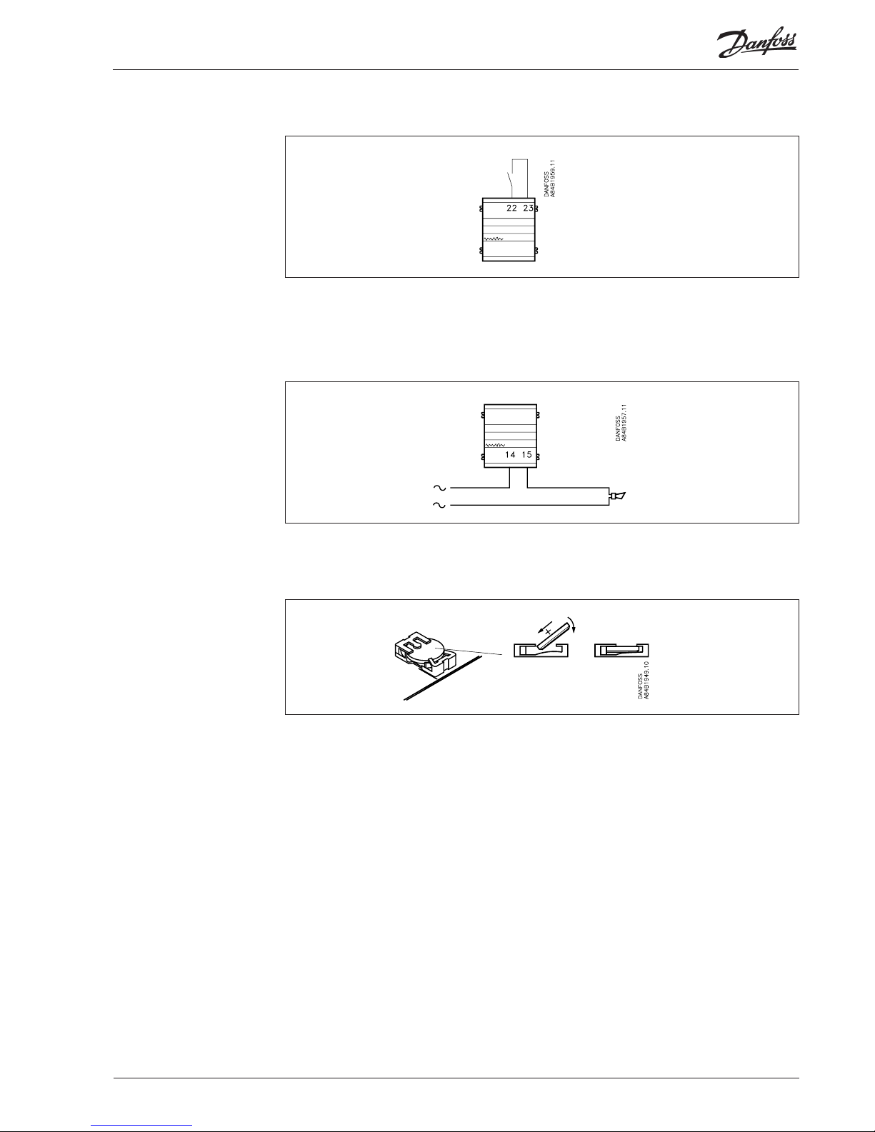
The printer port has been designed as a parallel printer port. An ordinary parallel printer cable is used
for the connection.
An EPSON compatible matrix printer can be connected.
The on/off input DI1 is connected to a pushbutton switch (pulse pressure with spring return).
When you push the switch, a signal is sent that the printer is ready and that the paper is correctly
placed.
1) As the last unit on the data
transmission cable:
The wire switches are kept
closed (BUS TERM “ON”)
2) The gateway retransmits the
signal:
The wire switches are opened
(BUS TERM "OFF").
Terminals:
No.
E3 B
E2 A
E1
LON
Printer
8 Manual RS8DT102 © Danfoss 09/2004 AKA 245
Page 9
You may change manually between two diff erent alarm routes. The DI2 ON/OFF input can be
connected to a contact function. When the DI2 input is cut in, the alarms will be sent via route 2
(optional des ti nations). (Cf. section “AKA Alarm Table”).
The DO2 output can be used for connecting an alarm function. There is connection between terminals
13 and 14 when the gateway is energised and there is no alarm. This connec tion is interrupted for two
minutes when a status 1 alarm is received from a control ler, or if the supply voltage to the gateway
fails.
Manual change-over of
alarm routing
Alarm relay
Battery
The gateway is provided with battery backup securing the settings and log collections.
When the battery needs to be replaced, an alarm message is sent.
When a battery is replaced, make sure that the supply voltage is not removed from the gateway. If the battery and supply voltage are both removed at the same time, the clock setup, log setup, collected log data,
master control setups and possibly EKC installation data will all be lost.
3 V
CR2032
AKA 245 Manual RS8DT102 © Danfoss 09/2004 9
Page 10
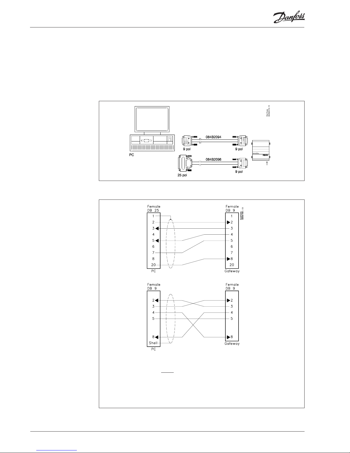
PC, Modem or server connection
(Only handshake signals DTR and CTS can be used)
The PC can stop the communication from AKA 245.
AKA 245 cannot stop communica tion from the PC.
The connection is made with a screened cable, wire diameter = 0.25 mm.
The screen is only connected to the plug at one end.
The length of the cable must not exceed 15 m.
A PC, a modem or a TCP/IP server can be connected to the RS232 plug. A setting in the gateway determines the application.
Warning!
In order not to destroy the output on the PC, the modem or the server the following precautions must be
taken:
- Establish the correct earth connection on AKA 245
- Interrupt the supply voltage to the gateway and to the PC / the Modem / the server, when the cable is
mounted and dismounted.
PC to gateway
Check whether the PC has a 9-pole or a 25-pole plug for this connection. A 3 m cable with plugs fi tted
can be supplied. See Ordering. If the cable has to be longer than 3 m, mount it based on the following
instructions:
10 Manual RS8DT102 © Danfoss 09/2004 AKA 245
Page 11
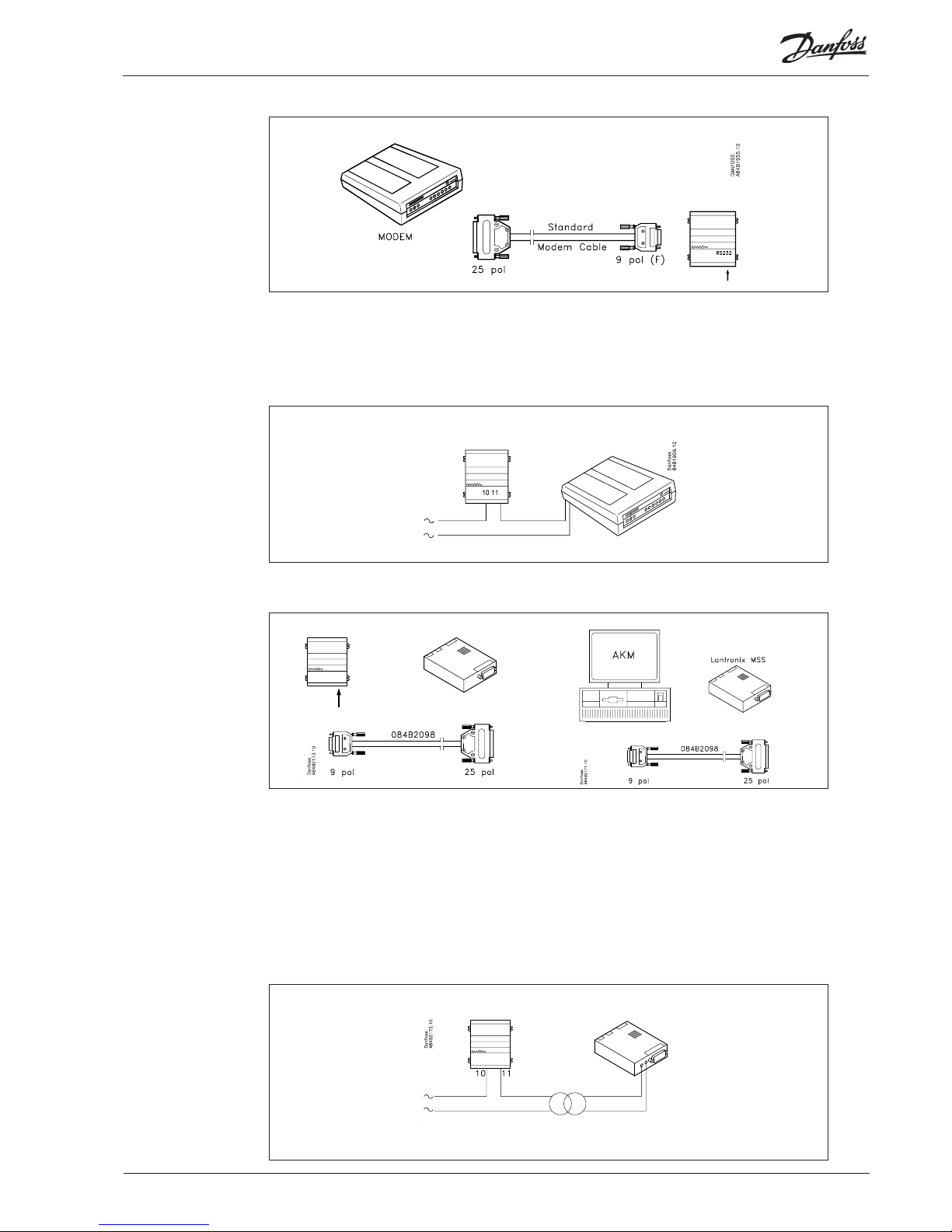
Modem to gateway
Use a standard modem cable.
Supply voltage to the modem must be connected, as illustrated (via DO1). This will permit AKA 245
to reset the modem. Also, the modem will be switched on and its start controlled, when AKA 245 is
switched on.
TCP/IP server to gateway and TCP/IP server to PC
So far two servers have been tested:
- ”Lantronix MSS 100” (shown above)
The server to be ordered from a Lantronix dealer.
A 3 m cable with plugs mounted to be ordered from Danfoss. See Ordering.
- ”Digi One SP” (Enclosure about half the size illustrated)
Server to be ordered from a Digi International dealer. Code number is 70001971.
Cable with plug is bypacked.
Supply voltage to the TCP/IP server must be connected, as illustrated (via DO1). This will permit
AKA 245 to reset the TCP/IP server. Also, the TCP/IP server will be switched on and its start controlled,
when AKA 245 is switched on.
AKA 245 Manual RS8DT102 © Danfoss 09/2004 11
Page 12
Functional description
The gateway that has been assigned the master function in a network automatically establishes a
table (plant list) containing the addresses of all connected units.
The gateway then picks up data from all these addresses (also its own) for this table. The obtained data
are the unit’s code number and software version.
For each address a user-defi ned text may now be added, logical name (ID code) or text describing the
function of the controller at the address in question.
This text can only be entered in the table by using the PC and system software type AKM (text may
contain max. 16 characters).
The master gateway may for example give a system name, and the other units a name for what they
are used for.
The entered text can now be displayed via system software type AKM or on control panel type AKA 21:
AKM: The text is used in many menu surveys in the programme. The text bears the designation
“ID code”.
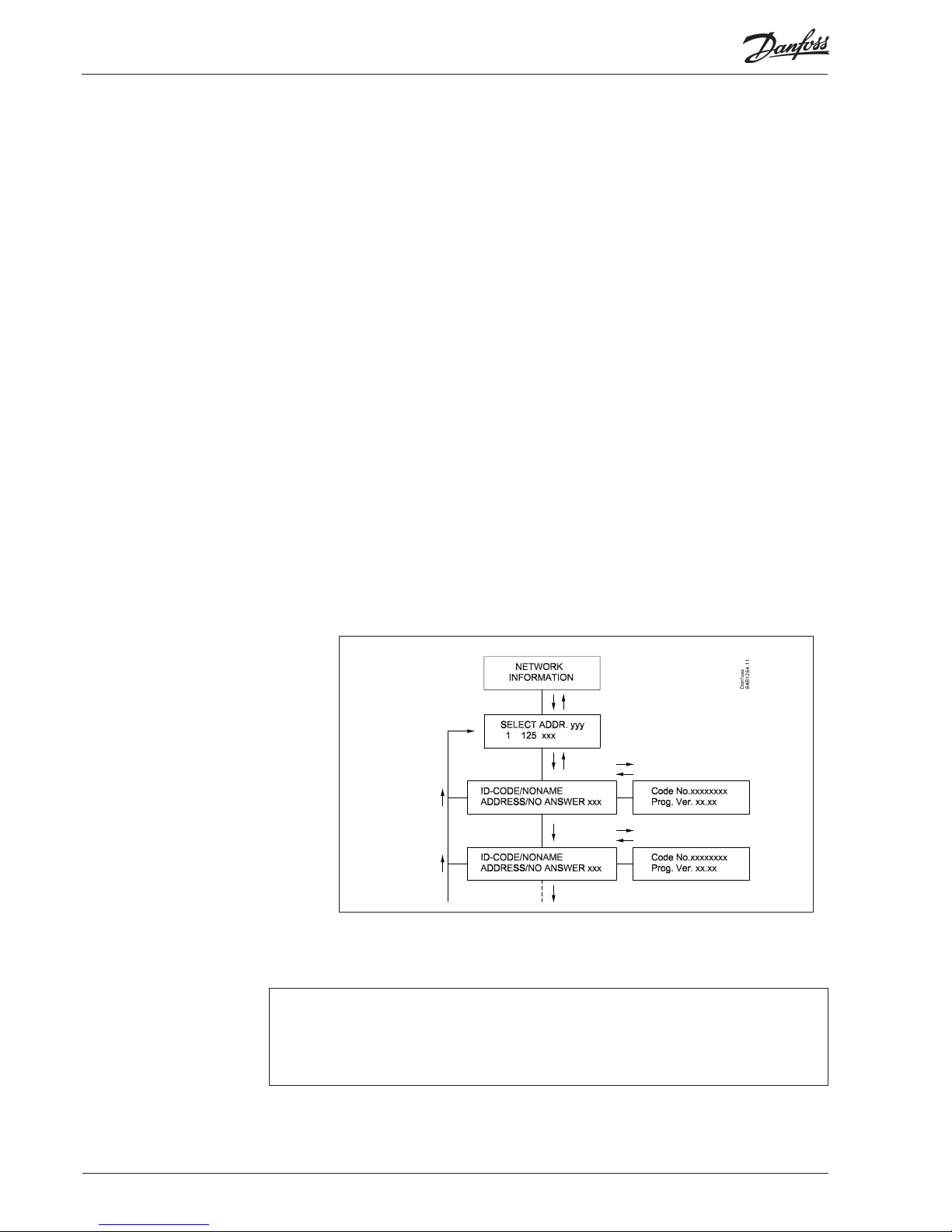
AKA 21: “Network information” can be read in the control panel’s display, as follows:
- select master gateway (address = 125).
- push key “F2” on AKA 21. The text Network-information will then appear. Now select
the individual addresses and read the text, code number and software version for each
controller.
The text will also appear in an alarm message on the printer, e.g.:
Transmitter 5:125
System-address: 5:1 LONDON_SOUTH_03 MILK
Received: 2000-08-17 14:06:47 Sta tus: 0
Communication OK (DANBUSS)
Network information
12 Manual RS8DT102 © Danfoss 09/2004 AKA 245
Page 13

This function will ensure that there is correct communication between the connected units on
DANBUSS and LON. There will be constant scanning of all units on DANBUSS and LON. If there are any
changes on DANBUSS (a unit drops out due to power failure, or a new unit suddenly appears on the
network), the function will discover it and issue an “Communication error (DANBUSS)” or “Communi-
ca tion OK (DANBUSS)”.
New units are found within fi ve minutes. Units that drop out will be found within two minutes (shortterm drop-outs will not be discovered).
In the LON communication an alarm will also appear if one of the connected controllers drops out. (A
new controller in the network will only be registered when the required function is activated in the
new controller (service pin message).
Alarm delay: A time delay can be set by means of system software type AKM. An alarm will follow when
two minutes plus the time delay have elapsed, at the latest.
The control function only applies to the gateway that has been assigned the master function (address
125).
The master gateway has a built-in clock function which is used for the following:
- time stamping of alarms
- synchronising the clocks in all connected AKC controllers, AK2 controllers and slave gateways
- change-over between summer/winter settings
The function is only active in the gateway that has been assigned the master function (address 125)
in a network. Only control lers in the same network as the gateway will have their clocks synchronised.
The clocks are synchronised after each start-up of the gateway, and after that at least once a day. If a
controller has been without power for more than two minutes, the clock will be synchronised when
the controller is again registered on network.
To set this function, use system software type AKM:
a) If you select “Auto setup” = “Enable”, the master gateway will set the following values in all connect-
ed control lers on the network:
- Fill in “System address” with the network’s own number and the control ler’s own number.
- Fill in “Alarm report to” with the master gate way’s own system address.
All controller alarms will now be transmitted to the master gateway.
b) If you select “Auto setup” = “No setup” (the factory setting in AKA 245), the master gateway will not
change the setting in the controllers. Chan ges can only be made on each individual AKC controller.
If a new unit is added to the network, the gateway will register it. Depending on whether “Auto setup”
is set in pos. “Enable” or “No setup”, the unit’s two menus will either be set or remain unchanged.
(In EKC controllers and AK 2 controllers a systems address is automatically set in the gateway for the
controller in question. The address cannot be read in the controller.)
c) If “Auto setup” = “Disable” is selected, the master gateway will cancel the alarm transmission in all
AKC and AK 2 controllers on the network. The procedure is, as follows: the gateway will itself set
“System address” to 000:000 in AK 100 and 20 and AK 2 control lers, and “Alarm report to” to 000:000
in all AKC and AK 2 control lers. With these settings, the control lers cannot send alarms to the
master gateway.
EKC controllers are not aff ected, but the gateway will stop the function asking for alarms in each
controller.
The AKA 245 defi ned as master gateway in a network will register all alarms that occur in this network.
The alarms are entered on a list (alarm list) where they will be ready for further processing.
The fi rst thing that happens is that a acknowledge (transport receipt) will be transmitted to the
controller that triggered the alarm (AKC controller/AK 2 controller). The controller will now know
that the alarm has been received and registered (if it did not receive this accept, the controller would
repeat the alarm message fi ve minutes later). The second thing that happens is that the alarm is timestamped and ID codes (net ID and bus ID) must be entered, if applicable.
The third, that the alarm will be passed on to the defi ned alarm receiver(s).
Communication control
Clock function
Automatic setup of
controllers alarm function
Alarm handling
AKA 245 Manual RS8DT102 © Danfoss 09/2004 13
Page 14

Alarms from EKC controllers will also be registered by AKA 245, but if the data connection between the
EKC controllers and the gateway is interrupted, only an active alarm, if any, will be present when the
connection is reestablished. In other words, all alarms occurring during the period without data communication will not be registered.
Alarm receipt
Alarms can be received in four ways:
1) The alarm is not passed on(factory setting).
The alarm is entered on the alarm list, but is not pro cessed. The DO2 alarm relay will however be
activated for two minutes on receiving a “status 1” alarm from a controller. The alarm list can be
displayed via control panel type AKA 21 or via system soft ware type AKM.
The alarm list can contain max. 250 alarm messages (the oldest ones are deleted).
System software type AKM is used for setting this function. In the alarm receipt menu for the
gateway in question, put “AKA Alarm Report To” in pos. “No ne”.
2) Alarm is passed on to the printer connected to the printer output.
The alarm is entered on the alarm list, but is also trans mitted to the printer.
DO2 is activated for two minutes when a “status 1” alarm is received from a control ler.
With the factory setting, the receiver of the alarm is the master gateway’s own system address.
(When system software type AKM is used, this system address will as regards function be identical
with setting 000:000).
3) Alarm is passed on in the system.
The alarm is transmitted to another master gateway in another network, or to the address of system
software type AKM.
DO2 is activated for two minutes when a “status 1” alarm is received from a control ler.
Use system software type AKM for setting this function. In the alarm receipt menu for the gateway
in question, put “AKA Alarm Report To” to “System address”, and defi ne the system address.
4) AKA alarm routing
The alarm is transmitted to the receivers defi ned in the alarm table. This function may for instance
be used when the gateway is mounted in a network, where a PC with AKM has not been connected.
Cf. the section “AKA Alarm Table”. (System software type AKM is used for setting this function).
Ad 2), 3) and 4):
It is a requirement that a recipient (also copy receivers) is always able to receive the message. If the
message cannot be delivered, the gateway will lock the relevant alarm line, so that the alarm can
be trans mitted at a later time. If the gateway receives further alarms, they will be entered as new
alarms. If the alarm in qu estion is then numbered “249”, no new alarms can be entered on the alarm
list. This will produce the system alarm “Alarm list overfl ow”.
In case of “Alarm list overfl ow” alarm relay DO2 will be activated every fi fth minute, until the alarms
can again be transmitted to the alarm receiver.
Example of alarm list overfl ow:
In the master gateway, the alarm receiver “AKA send alarm to” has been set to “System address”, but
no printer has been connected, or it has been turned off :
In this situation it will be able to receive the fi rst 249 alarms, and after that it will try every fi fth
minute to retransmit the oldest alarm to the printer. Alarm No. 250 will trigger the system alarm
“Alarm list overfl ow”, and from now on no more alarms can be received. If there should be more
alarms from the control lers, these alarms will be retransmitted every fi fth minute, and these
retransmissions will gradually hamper the communication in DANBUSS so much that the data
transmission is blocked. If more alarms should occur in an AKC controller than it can hold (20), these
new alarms will not be registered.
If the printer is connected at this point, it will make a printout of all alarms, and the master gateway
will again be able to receive alarms.
In this example, the selected setting “AKA send alarm to” should be “none”, rather than “System
address”.
Appendix B contains a description of repeat routines for alarm transmissions when calls are not
successful.
14 Manual RS8DT102 © Danfoss 09/2004 AKA 245
Page 15

Alarm list in AKA 245
The alarm list can be displayed from system software type AKM or from control panel type AKA 21.
From AKM: via the “History" - "AKA Alarm List” menu.
From AKA 21, as follows:
- select the master gateway (address = 125)
- push key “F1” on AKA 21. The text ALARM LIST will then appear.
- now select the individual alarm numbers and display the text for each of them.
Alarm status
The individual messages on the alarm list will contain information about the status of the alarm.
Each alarm is defi ned with a degree of importance in the individual controllers. When an alarm is dealt
with, it will be assigned an actual status.
A sensor error, for example, will generate two independent alarm messages. One when the error arises
(status = 1), and another when the error is corrected (status = 0).
Status: 0 Alarm cancelled (error corrected)
1 Alarm is active. The alarm is sent out on DANBUSS and the master gate way’s alarm relay is
at the same time operated for two minutes (impor tant alarm)
2 Alarm is active. The alarm is only sent out on DAN BUSS, as a not so impor tant alarm (a mes-
sage).
3 As "1", but the alarm relay on the master gateway will not be activated.
AKA 245 Manual RS8DT102 © Danfoss 09/2004 15
Page 16

AKA Alarm Table
(alarm routing)
This function can retransmit received alarms to diff erent alarm receivers via the DANBUSS data communication system.
The alarm routing can only be defi ned in the gateway that has been assigned the master function (address 125).
Alarm routing takes place on the basis of an alarm table where two diff erent groups of receivers can
be set.
1) Default destinations, route 1, which is the normal receiver group.
2) Optional destinations, route 2. This is the route you use if one of the following conditions is met:
- Contact function DI2 is cut in (manual change-over)
- The time lies within the defi ned time limits (time-based change-over)
The table can contain ten lines, and each line shows an interval (a start and stop time with
indication of day of the week, hour and minu tes).
A line in the table cannot overlap a change of week. Where Sunday changes to Monday, two lines
have to be used in the time table.
Four receivers can be defi ned for each route, as follows:
- Primary:
Alarms are sent to this receiver, if a system address has been defi ned.
- Alternative:
Alarms may be sent to this receiver, if a system address has been defi ned. The alarm will
however only be sent to this receiver, if the primary receiver has not been able to receive the
alarm.
- Copy:
“Alarms” may be sent to this receiver, if a system address has been defi ned. An alarm will not be
sent to this receiver until the primary or alternative receiver has received it, and acknowledged
receipt of it.
- DO:
The DO2 relay output of the defi ned master gateway is activated for two minutes if the function
is selected. The activation of DO2 is independent of the settings made for primary, alternative
and copy receivers, irrespective of whether alarms are to be retransmitted at all. (DO2 is only
activated for status 1 alarms).
The alarm table has to be set by means of system software type AKM. Please note that AKM is also
capable of routing alarms. It is recommended that only one of the two options be used on the same
system.
(When AKA 245 is delivered ex stock, the alarm table is not active).
Appendix B contains a description of repeat routines for alarm transmissions when calls are not
successful.
16 Manual RS8DT102 © Danfoss 09/2004 AKA 245
Page 17

Printer function Alarm printout
The master gateway (adr. 125) contains a function that can receive alarm reports from controllers,
reformat the messages and print them on a connected printer, type Epson compatible matrix printer.
For this function to be used, the controllers must be set to transmit its alarms to a gateway with
connected printer. Cf. section: “Automatic setup of controllers alarm functions”, page 13.
The alarm printout function supports AKC controllers in series AK 20 and AK 100. As well as EKC
controllers in the 200, 300,400, 500 and AK 2 series.
Example of alarm printout from an AKC controller:
Transmitter 5:125
System-address: 5:1 LONDON_SOUTH_03 MILK
Received: 2000-08-17 14:06:47 Sta tus: 0
Communication OK (DANBUSS)
Alarm printout from PC
A printer connected to AKA 245 can print an alarm report from a PC connected to DANBUSS.
To use this function, a datagram of a special format has to be transmitted to the gateway. This means
that it is in practice the application software in the PC and the internal software in the gateway that
use this facility.
If the alarm is routed from the AKM alarm table directly to the gateway printer, custom texts, if any, will
be included in the print. If the alarm is however routed to “AKA Alarm receiver” the custom texts will not
appear, but the alarm relay - DO2 - will be activated for two minutes.
Printer alarm
The printer function can send an alarm message to a connected PC, if errors arise on the connected
printer. Alarms will be sent to the master gateway on its own network. This will however not happen if
the printer is connected to a ”slave gateway”.
If no printer has been connected to a gateway, this will also produce an alarm message at the
gateway’s fi rst start-up.
Control panel type AKA 21 cannot control a printout function.
Certain texts in connection with printout of alarms etc. can be set from the AKM programme.
AKA 245 Manual RS8DT102 © Danfoss 09/2004 17
Page 18

Data collection in the master
gate way
Data collection can take place in the gateway, defi ned to be the system’s master.
In connection with defi nition, start, stop and display of a data collection (logs), a switch will be
required for the PC. During the remaining time the gateway will take care of its own collection of data.
Data may thus be collected in a system which is not directly connected to a PC. The collected data may
subsequently be trans mitted to a PC from time to time, so that it can be displayed. The transmission
can, for example, be accomplished via a telephone connection.
Two diff erent log types can be established in the master gateway:
1) Food Safety logs (logs required by the authorities) and
2) AKA Service logs.
The diff erence between these log types is mainly the intervals at which data can be logged, and hence
the duration of the period of time the memory is able to accommodate.
Limitations:
- Max. 170 logs can be set up in a master gateway (120 Food Safety logs and 50 AKA Service logs).
- Each log will represent one controller
- Each log can max. contain 13 parameters.
- The time interval for Food Safety logs is between 15 minutes and 24 hours.
- The time interval for AKA Service logs is between 1 minute and 4 hours.
- The master gateway can totally contain about 60,000 data collections.
Examples of log capacities for diff erent sizes of systems are shown in Appendix C.
The log function will continuously collect and store data from the controllers connected to the
network for which the gateway in question is the master.
Defi nition, start, stop and display of a data collection (logs) must be carried out with system software
type AKM.
All logs in the master gateway are “rolling” (temporary) logs, in other words, the data will be
overwritten, if they have not been collected during the set period of time (deadline).
The log setup will be deleted and all collected data lost, if the system address of a master
gateway is changed or if the supply voltage is removed and the battery is defective or
dismantled.
If logs are deleted (one log or all of them), without the logged data having been stored, such data will
be lost. There will be no alarm when such deletion takes place.
When a log is started, data collection will not necessarily take place immediately, as all readings of
data will be carried out at set times after the log interval.
This means, for example, that for logs with 15-minute intervals the data will be read at times that are
multiples of the 15 minute-period, i.e. when the minute hand points to 0, 15, 30 and 45. Similarly, a log
with an interval of two hours will be read every other even hour, i.e. at 0am, 2am, 4am, 6am etc., up to
and including 10pm. And a log with an interval of six hours, at 0, 6, 12, 18. These fi xed logging intervals
cannot be changed.
If a log has been stopped for a while, and is then restarted, some data will be missing for the period
that was skipped.
The master gateway constantly controls all log setups via a simple check-sum calculation. If there is an
error, the log in question will be deleted. An alarm will now be given with information about the log
number.
18 Manual RS8DT102 © Danfoss 09/2004 AKA 245
Page 19

AKA 245 can act as connecting link between DANBUSS and a modem.
(DANFOSS can provide information about other modem types that can be used with the gateway)
By connecting the supply to the modem via a relay switch (DO 1) on the gateway, the gateway will
be able to reset the modem. At the same time the modem will be switched on, when the gateway is
switched on. This ensures that the modem start will always be controlled.
Read the section “Connections”.
It is possible for the gateway to use commands for control ling the connec ted modem. These
commands are in the form of an initialisa tion string transmitted to the modem when it is switched on.
From the factory a modem gateway contains the following AT command string:
AT Z < CR > AT E1 SO = 2 &D2 V1
The command has the following meaning:
AT Attention sequence
Z Reset modem to power-up status
E1 Echo on
V1 Verbose result codes(e.g.”CONNECT 1200" instead of “4”).
&D2 HW mode for on hook via DTR
S0=2 Auto answer ON, answer after 2 rings
The initialisation command string can be changed by means of system software type AKM.
E0, V0, S0=0, S0=0, &D0, &D1 and &D3 must not be contained in the command string.
For further information about these commands, please refer to your modem manual.
A number of modem codes can be keyed in together with a telephone number.
These modem codes attach to a specifi c telephone number and are sent on to the modem together
with the telephone number.
The following codes can be keyed and attached to a telephone number in the router table:
P: Pulse dialling. Used in old telephone exchanges and private switching systems.
T: Tone dialling. Used in new telephone exchanges.
W: Wait for ringback tone (dial tone)
, : 2-second pause
%n: Modifi es the calling speed for this particular call
* : Special character for private switching system
# : Special character for private switching system
For further information about these commands and codes, see the modem manual.
Call-back function
The function can be used for service and transmission of log data via the telephone network.
The call-back function is selected from the AKM programme and is essential for all systems from which
service or log data are collected.
The function sees to it that the gateway will return the call to the AKM programme, and hence pay for
the transmission time.
Procedure
The AKM programme calls the master gateway and starts the call-back function. The master gateway
then checks if the AKM programme’s system address is found in the router table.
15 seconds later the master gateway establishes a telephone connection to the AKM programme. If
the connection is not established at the fi rst try, two more attempts will be made at 5-minute intervals.
When the master gateway has established the telephone connection the AKM programme will take
over.
An automatic log transmission is carried out in this way:
Based on the individual log defi nitions, the AKM programme knows how often it has to collect data
from a system. The AKM programme starts the procedure, and when the connection has been established, the collection will commence.
If the master gateway does not manage to establish a telephone connection, the AKM programme will
call the master gateway again, and collection will then be started immediately.
Modem connection
TCP/IP server connection If data communication is to take place via a LAN network (TCP/IP) the gateway can be connected to a
server.
Principle, connection and settings are described in the installation instructions for AKM.
Literature No. RI8B.P--.
AKA 245 Manual RS8DT102 © Danfoss 09/2004 19
Page 20

AKA override function AKA 245 contains a function capable of reading values from a given function in a given controller on
Data communication. The gateway will treat the information and then set the values in other selected
controllers in the system. Each individual controller will subsequently carry out the given function. You
can max. download data from 100 controllers. Otherwise the data communication will be overloaded.
The functions are also described in the document ”Overriding, RI8AL-”.
At the moment the following functions can be arranged:
AKC ON signal
This function is used for stopping the regulation (closing the valve) in all controllers regulating a refrigeration appliance when all belonging compressors are stopped.
Example: When the compressor is stopped, the compressor control sends a signal via data communication. The master gateway subsequently sends this signal on to the defi ned controllers which will then
close the valve.
Displacement of alarm limit
This function is used for raising the alarm limit during a period where the compressor control is unable
to cut in more capacity.
Example: On an extremely hot summer day where the outdoor tempera ture exceeds a set value, the
control will generate an off set signal that will depend on a signal from a room sensor. The off set signal
will then be retransmitted to the defi ned controllers which will raise the limit of the high-temperature
alarm.
Defrost control
The function can transmit signal concerning defrost start to the diff erent refrigeration points.
All defi ned controllers will follow the signal. When defrost has started it is up to the individual controllers how it is to be stopped again. Some are based on time, others on temperature. The defrost is started
by a week-based one-year clock in the gateway.
Day/night function
The function can send signals about night operation to the diff erent refrigeration points. All the defi ned
controllers will follow the signal. The signal is generated by a week-based one-year clock in the gateway
or from a digital signal on a controller.
20 Manual RS8DT102 © Danfoss 09/2004 AKA 245
Page 21

PO optimisation
The function adapts the refrigeration system’s suction pressure so that it will not become so low that
the most heavily loaded refrigeration appliance is unable to maintain the required temperature.
The procedure is that the gateway constantly makes enquiries with the selected refrigeration
appliances following which it transmits signals to the compressor control.
AKA 245 Manual RS8DT102 © Danfoss 09/2004 21
Page 22

Operation
On AKA 245 there are no buttons. The unit is ex clusively operated via control panel type AKA 21 or
system software type AKM.
Operation from AKA 21 takes place via a menu system coded into the gateway.
The gateway menu structure has been “lowered” in relation to the menu struc ture of the AKC
controllers. Change between menus takes place by means of the control module’s arrow keys.
Display
The display in AKA 21 has two lines with 16 characters each.
Function
The fi eld describes the available menu.
Value/setting
The fi eld shows the current value.
Min and Max
The fi eld indicates the possible min. and max. values
of the setting.
New
In this fi eld a new value is selected. The fi eld will be
empty when there is a para meter that cannot be set.
F1
Used for displaying the “alarm list” found in the master gateway (address
125).*).
F2
Used for displaying the “NETWORK INFORMATION” (system table) found in the master gateway
(address 125).*)
Clear
Return to the gateway's access menu.
Arrow keys
Used for moving about in the gateway’s programme (menus).
Digit
Used for selecting the digit that has to be changed.
+/On , -/Off
Used for selecting a new value. It will either be a fi gure or a changeover bet ween on/off functions.
Enter
Used for confi rming new settings. If a changed display is left without “Enter” having been pushed, the
new value will not be stored.
F3, “key” and Help
Not used for gateway operation.
*
) If national characters and ID codes are used for alarm texts from AKC controllers, these characters
will not be presented correctly in the AKA 21 display.
Principle
Operation via AKA 21
22 Manual RS8DT102 © Danfoss 09/2004 AKA 245
Page 23

Access limitation
Printer function
Operation via system
software type AKM
If a PC with system software type AKM is connected to the system, it will be possible to:
- perform all settings from the PC
- receive alarms on the PC
- connect a printer to the PC where printouts will be made of all alarms
AKA 245 are protected against inadvertent settings and changes of parameters from AKA 21. This is
done by means of access limi tation dis tributed on three levels:
1) Normal “Daily user level”
2) Extended “Engineers level”
3) Service “Service level”
The level limits can be changed in the unit (see section “Settings”).
When the gateway is used in conjunction with system software type AKM, a password function may be
used. This function will block settings when the system is operated via the telephone network and the
password is not known.
For the sake of users of AKM it is however permitted to read and set a few functions. However, access
will not be given to important functions like router lines, upload functions and ID-codes.
The password function must be initiated with system software type AKM.
On AKA 245 there is one way only of operating the printer function.
By activating input DI 1, the gateways internal line counter is zero-set. In this way it is possible to keep
a check on the printer paper perforation.
DI 1 is activated when the printer is switched on, and the printing head is placed in start position on
the fi rst writing line (top of form).
Re setup, installation, insertion of paper in the printer etc., reference is made to the printer’s own
manual.
Password function
AKA 245 Manual RS8DT102 © Danfoss 09/2004 23
Page 24

Settings
General In the gateway you have to set up the parameters that are to govern the individual functions. The
parameter setup is grouped accor ding to the functions governed by the parame ters.
GATEWAY, Code
Access display and keying of number giving access to the gateway setup.
Time setting
Setting of gateway timer; including changeover between summer and winter time.
Confi guration
Reading of programme version.
Setting of access codes.
Settings concerning “AKA 21 log off ”
Reading of whether password is used, and deletion of the use of it, if applicable.
System adderess: (and GW type at AKA 245)
Setting of the gateways actual DANBUSS system address.
An AKA 245 nust be defi ned for either PC gateway, modem gateway or TCP/IP gateway.
Communication setup
Router: Setup of router tables.
RS 232: Communication speed at port.
LON port: Setup of address range for LON bus
The individual setups are explained on the following pages.
At the end of the manual there is a complete menu survey.
When initial startups are made on systems with two or more gateway's on the same network, special
precautions have to be taken.
If a network with several identical addresses is started, the DANBUSS system will not function.
All gateways are factory-set with address 125. (0:125).
The initial start-up must be carried out in one of the following two ways:
1) Set all addresses before the gateway is placed in the network. (AKA 21 is used)
2) Connect only supply voltage to one gateway at a time, assigning the master status to the last unit to
be connected (master address = 125). (AKA 21 is used).
Note 2
When changes are made in the unit setup, they are stored in the unit’s memory. Activate the “Boot
Gateway” display (AKA 21 must not be operated again, until the gateway has fi nished its
initialisation and scanning functions in the connected DANBUSS network, which takes approx. 30
seconds). After that, the new settings will be active.
Note 3
If the gateway type has to be changed (PC/Modem/TCP/IP) it can only be done with the battery
mounted.
24 Manual RS8DT102 © Danfoss 09/2004 AKA 245
Page 25

GATEWAY, Code. Access
display and access code
Access to the gateway takes place with control panel AKA 21 in the same way as for other controllers
on DANBUSS.
Shown in the AKA 21 display are the units that are connected to DANBUSS. The AKA 245 gate way is
symbolised with a “G”.
< 125 > 125
AAE A A G
AKA 245 with assigned address = 125 is depicted here
A gateway that has been assigned the master function will have address No. 125.
When you push “arrow right”, the display will show addresses higher than 16.
Select gateway by using the “+/ON” or the “-/OFF” key, and then pushing “Enter”.
The following access display will now appear in connection with a PC gateway:
PC GATEWAY
Push “arrow down” to proceed to the menu where the access code has to be keyed.
Code
XX
Factory-set access codes:
Extended access code = 40. This will give access up to and including the menu section “TIME
SETTINGS”.
Service access code = 99. This will give you access to the whole unit.
After keying the code, push “Enter”, and the access display will appear again. Now push “arrow right” to
continue the setup.
AKA 245 Manual RS8DT102 © Danfoss 09/2004 25
Page 26

Time setting.
Clock function
“Time setting” Access to setting of timer and changeover between summer and winter time.
The timer in the gateway is an annual timer that can change between summer and
winter time.
The timer will itself determine the day of the week based on year and date, and it
will not accept incorrect settings. If an attempt to set the month, for example, is not
crowned with success, it may be because the date has a wrong value.
The timer’s second-counter is zero-set when the minutes are set.
The timer is provided with battery back-up and will keep on working if there is a
power failure.
“Year” Setting of year.
“Month” Setting of month
“Date” Setting of date.
“Hour” Setting of time.
“Minute” Setting of minute.
“Summer time” Display of changeover between summer and winter time, and access to settings.
Select either “off ”, “auto” or “manual”:
“Off ” Changeover between summer and winter time interrupted.
“Auto” Changeover is performed automatically based on the rules applying to most of
Europe. (Last Sunday in March and October)
“Manual” Here you specify the date and hour of the two changeovers. The change over can
only be made with full hours. The settings will remain valid, until a new setting is
made.
If “Auto” has been selected, settings cannot be made.
“Start” Access display for setting the start of the summer time.
“Stop” Access display for setting the stop of the summer time.
“Month”, “Date”, “Hour”:
Setting of time
26 Manual RS8DT102 © Danfoss 09/2004 AKA 245
Page 27

Confi guration.
Access codes and
display
“Confi guration” Access to reading of programme version and setting of access codes/
parameters concerning DANSETT logoff .
“Code no.” Reading of AKA part No.
“Prog. ver.” Reading of programme version
“Normal limit” Setting of access level without using an access code. (A complete
menu survey is shown at the back of the manual).
Choose between the following settings:
1: No access to settings
2: Access up to and including “Time setting”.
3: Access up to and including “Confi guration”.
4. Access up to and including "System address".
5: Access to all menus
“Extended limit” Setting of access level with the use of the “Extended code".
Choose between the following settings:
1: No access to settings
2: Access up to and including “Time setting”.
3: Access up to and including “Confi guration”.
4. Access up to and including "System address".
5: Access to all menus
“Extended code” Setting of code to be keyed at logon, to obtain extended access.
“Service code” Setting of code to be keyed at logon, to obtain service access (access to all
menu items).
“Dansett time” Setting of time of automatic logoff . (If the gateway has not been operated
during this period, there will be logoff ). The time will be indicated in
seconds.
“Dansett logoff ” Show the display possibility on AKA 21 of automatic logoff :
“Supervise mode”, “Select mode” or “Reset”. See next point.
“Change logoff ” Selection of displays for “Dansett logoff ”. Setting = 2 should be used, if AKA
21 receives its power from an AKC controller or from an external power
pack:
0: “Supervise mode”: This setting can be used with advantage in small
systems.
When AKA 21 is not operated for, say, three minutes, the display will by
turns show access pictures on all connected controllers.
1: “Select mode”: AKA 21 shows the menu where DANBUSS unit is selected.
2: "Reset": AKA 21 shows "Dansett" ready, press any key”.
When a key is pushed, AKA 21 will show the menu where a DANBUSS
unit is selected.
Password Settings can be protected with a password. The password can only be set
via the AKM programme version 4 (but may be deleted via AKA 21 without
it being known).
The password will protect against:
- reading of router lines and system confi gurations
- setting of router lines and alarm setups
AKA 245 Manual RS8DT102 © Danfoss 09/2004 27
Page 28

“Network”
Setting of the network number at which the gateway is installed.
Valid network numbers: 1 to 255.
“Address”
Setting of gateways address.
This setting corresponds to the setting of addresses on the AKC controllers’ DIP switches.
To allow communication there must be one, and only one, master on each network. This is arranged
by always giving the master address No. 125.
If there is only one gateway on the network, it is given address 125. Other gateways on the same
network are assigned other addresses. This also applies to such units as AKC controllers.
(The factory-set address in a gateway 125. The address no. 124 is not polled on DANBUSS. The valid
address for a AKA 245 will there for be 1 to 123 (not within the LON address range, however) or 125.
"Change GW-Type"
An AKA 245 can be defi ned to either operate as a PC gateway, a modem gateway or a TCP/IP server.
The defi nition is made with the following setting:
0: PC gateway
1: Modem gateway
2: TCP
The actual setting may always be seen in the gateway’s access display.
Address & GWtype
Address and gateway type
28 Manual RS8DT102 © Danfoss 09/2004 AKA 245
Page 29

Communication setup. Setup
of communication
“Communication setup”
The menu gives access to the following three submenus.
1) Router (Routing)
Before the router function is set, it is necessary to know the principle of how the messages are circulating
between the diff erent units.
This principle is explained in Appendix A.
“Edit line” Here you select a line that has been established in the router table. Only previously
established lines can be selected and subsequently changed. If no router lines
have been established, the display will show “No lines to edit”.
“Add line” Will establish a new router line immediately after the last existing line in the router
table.
After the establishment of a line, change to “Edit line” to continue the setup.
The router table can max. contain 10 lines if it is set for PC or TCP/IP gateway, and
250 lines if it is set for Modem gateway.
“Delete line” Deletes a selected line in the router table.
“Lower limit” Display of the “Lower Limit” fi eld for a line selected in the router table.
The value indicates the network to which a message is to be transmitted. Setting
takes place in the “Network” menu.
“Upper limit” Display of the “Upper Limit” for a selected line in the router table.
The value indicates the fi nal network to which a datagram has to be trans mitted.
Setting takes place in the “Network” menu.
“Port no.” Setting of the “Port No.” fi eld for a selected line in the router table.
The datagram is routed to a port, according to the settings shown below.
1: Datagrams to be sent via DANBUSS.
2: Datagrams for either PC, modem or TCP/IP server connection.
“Address” The menu contents are determined by the setting in the gateway type and of the
value selected under “Port No.”:
a) PC :
Display and setting of the “Address” fi eld for a
selected line in the router table.
Selection of port number =
1: Address number of the unit the datagram is to
be sent to in the net work is indicated here
2: Address is not set.
PC: See "a"
Modem: See "b"
TCP: See "c"
AKA 245 Manual RS8DT102 © Danfoss 09/2004 29
Page 30

b) Modem
Display and setting of the “Address”
fi eld for a selected line in the router table.
Selection of port number =
1: Address number of the unit the
datagram is to be sent to in the network is indicated here
2: The telephone number the
modem is to call is indicated
here.
“Telephone number”
Acess display
“______________x”
The actual telephone number for the selected line in the router table.
The telephone number may consist of up to max. 30 signifi cant digits
compo sed of fi gures and modem codes. All telephone numbers must be
terminated with ‘x’ (see below).
“Digit”
Selection of digit to be keyed/changed. Only one digit is selected.
“Digit xx Value.”
Digits/codes that can be keyed:
The fi gures 0... 9 are digits of the telephone number.
Figures above 10 are modem codes.
For a description of the codes, see the modem manual.
0... 9
10 = x: End of telephone number
11 = P: Pulse signalling
12 = T: Tone signalling
13 = W: Wait for new dial tone
14 = ,: Pause for 2 seconds
15 = %n: Modifi es baud rate
16 = *: Special character for private switching system
17 = #: Special character for private switching system
Example:
0W 12 34 56 WP 78 9x
where the digits have the following signifi cance:
0 “get a public line”
W “wait for new dial tone”
1 - 6 “phone number 123456”
W “wait for new dial tone”
P “choose pulse signalling”
7 - 9 “through-call to extension 789”
x “end of telephone number”
c) TCP/IP
Setting performed as for modem. Just set an IP address instead of a telephone
number.
30 Manual RS8DT102 © Danfoss 09/2004 AKA 245
Page 31

2) RS232 Port (PC Port)
The setup depends on the setting in the gateway type:
PC
“RS 232 Speed”
Display of the communication speed on
the RS 232 line, and access display
for settings.
“Change speed”
The required communication speed
is set here.
1: 1200 Baud
2: 2400 Baud
3: 4800 Baud
4: 9600 Baud (factory setting)
5: 19200 Baud
6: 38400 Baud
Re selection of communication speed, see the PC manual/software appli cation manual.
"Boot gateway"
When changes have been made in the unit’s communication settings, they have to be stored in the
unit’s memory. Activate the “Boot Gateway” function. Now Wait about 30 seconds. The new settings
will now be active.
Modem and TCP/IP
“Lifetime”
This is the period during which a gateway
maintains a connec tion after a datagram has
been transmitted via the line.
Selection of this parameter is based on the
point of view that there should be time for
the answer datagram to be returned during
the same connection. The time is set in
seconds (e.g. 10 sec.).
“RS 232 Port speed”
Display of communication speed, and access to settings.
"Changed speed"
The required communication speed is set here.
0 = 300 Baud
1 = 1200 Baud
2 = 2400 Baud
3 = 4800 Baud
4 = 9600 Baud (factory setting)
5 = 19200 Baud
6 = 38400 Baud
Re selection of communication speed, see the modem manual.
“Boot gateway”
When changes have been made in the unit’s communication settings, they have to be stored in the
unit’s memory. Activate the “Boot Gateway” function. Now Wait about 30 seconds. The new settings
will now be active.
AKA 245 Manual RS8DT102 © Danfoss 09/2004 31
Page 32

3) LON Port
The function defi nes a valid address range for controllers on the LON bus.
The function can also replace the activation of menu O04 in all EKC controllers as well as activation of
”Service pin” in an AK 2 controller.
Settings must be terminated through activation of BOOT-Gateway – Press ENTER.
Address range
The total address range for the connected controllers is from 1 to 120. Part of the range must be assigned to the LON bus. The remaining part is used by the DANBUSS.
Example
32 Manual RS8DT102 © Danfoss 09/2004 AKA 245
Page 33

Appendix A
Routing
This section contains a more detailed description of the router setting on page 27.
The DANBUSS system is a so-called compact coupled network. This means that information is
transmitted through the system as single messages, also referred to as datagrams. To ensure that the
datagrams reach the correct receivers in systems with many connected units, the transmitter must
enter the receiver’s address in the datagram. It is now up to the router in the DANBUSS system to
direct the datagram to the correct receiver.
To enable the router to distinguish between the individual units connected to the DANBUSS system,
each unit must be given a DANBUSS system address.
This system address is written in the “Network:Address” mode, where “Network” is the network number
and “Address” the address of the unit in question.
“Network” can assume values in the range 0-255.
“Address” can assume values in the range 1-125.
It is important that all units on the same network have the same network number.
Example:
The example shows a system consisting of two networks.
1) PC connected to AKA 245
2) AKA 245 and AKC controller
1:1 means network number 1 with address 1.
2:115 means network number 2 with address 115.
The example shows 1:1 sending a datagram addressed to 2:115.
The datagram is delivered to DANBUSS who will now be responsible for the transmission.
To ensure that datagrams are sent to the correct receiver, the system must contain information
about the composition of the DANBUSS network (the network may consist of several interconnected
networks). Information about the composition of the DANBUSS network must be entered in the socalled router tables.
There must in principle be router tables in all units that are connected to
DAN BUSS. Certain units, like AKC controllers, can however do without them.
To enable communication in systems with several networks, there must be at least one router table in
each network. The gateway enables you to set up one or more router tables.
General
Routertable
AKA 245 Manual RS8DT102 © Danfoss 09/2004 33
Page 34

A router table may have a varying number of lines. In the example shown below there is one line.
The table always consists of four fi elds when operation takes place with AKA 21:
“Lower Limit”, “Upper Limit”, “Port No.”, and “Address”.
1234
Lower limit Upper limit Port No.
Address/
Telephone no/
IP Address
112
In principle the fi elds indicate the following:
Fields 1 and 2: a group of units capable of receiving / sending a messa ge.
Field 3: the direction in which the message is to be sent.
Field 4: indicates the unit which is the next receiver of the message. From this position the following
may happen:
1) The message is sent on to another network (in which case a new router has to be
established with a new port and a new address).
2) The message is sent to a PC on the RS 232 output.
Below follows a more detailed description of the fi elds.
Field 1 + 2: “Lower Limit”, “Upper Limit”
These are network no. which together indicate an interval range between a lower and an
upper network limit.
Field no. 3: “Port No”.
There are two ports through which datagrams can be directed. “Port No.” indicates the
direction in which the datagram has to be transmitted.
Port 1: Access to units connected to DANBUSS
Port 2: Access to either a PC, a modem or a TCP/IP server.
Field 4: “Address”
The contents depend on what was specifi ed in the fi eld “Port No.” :
If “Port No.” = 1 (DANBUSS):
An address is indicated for the next receiver of the datagram. This may either be the
fi nal receiver for whom the datagram was intended, or it may be the address of another
AKA 245, say, a modem gateway that has to re-transmit the datagram.
If “Port No.” = 2 (RS 232):
At connection to a PC no address has to be entered, as only one PC can be connected.
In operation via the control panel the menu system will automatically detect this, and it
will not be possible to key an address.
On modem gateway or TCP/IP server you key the telephone number (in the fi eld “Address”) that is to be called or the actual IP address.
Appendix A - continued
34 Manual RS8DT102 © Danfoss 09/2004 AKA 245
Page 35

When an AKA 245 receives a datagram that has to be re-transmitted to an AKC controller, for example,
the gateway checks its router table to see where this AKC is placed. It is either placed in the same
network as the gateway, or it is placed in another network. In the former case, the gateway can send
the datagram directly to the fi nal receiver. In the latter case, the gateway must send the datagram to
another AKA 245 which will then re-transmit the datagram.
The access key to the router table is the system address (Network : Address) of the receiver of the
datagram.
Example 1.
A system consists of a PC on network 1, and two AKC controllers on network 2.
The AKC’s are addressed with 2:1 and 2:2, respectively.
The PC is addressed with 1:1.
AKA 245 is addressed with 2:125 (and this makes it the DANBUSS Master).
The PC wants to send a message to the AKC with system address 2:1.
The datagram is fi rst sent to AKA 245 who checks its router table to see where the datagram has to be
routed.
As the controller is on the same network as the master gateway, it will transmit directly to the controller (a router line will not be required).
The router lines shown are needed to allow messages to be sent from the AKC controllers to the PC.
Example 2.
A system consists of a PC in network No. 1, a PC gateway, two AKC controllers and a modem gateway
in network No. 2.
Network 5 consists of one more modem gateway as well as two AKC controllers.
The AKC controllers are addressed with 2:1, 2:2, 5:1 and 5:2, respectively.
The PC gateway is addressed with 2:120.
The two modem gateways are addressed with 2:125 and 5:125. So in both networks it is the modem
gateway which is the Master.
The PC is addressed with 1:1.
Appendix A - continued
Function
AKA 245
AKA 245 Manual RS8DT102 © Danfoss 09/2004 35
Page 36

The PC will now send a message to the AKC unit which is addressed 5:2.
The datagram is fi rst sent to the PC gateway which checks in its router table to see where the
datagram has to go.
In checking the router table the PC gateway will look for the line in the table where the receiver’s
network are contained. This requirement has been fulfi lled by line 2, as it indicates the network No. 5.
After the “Port No.” fi eld has been read, the datagram is directed out of gate 1 which is DANBUSS.
After furthermore having read the “Address” fi eld, it will be seen that the datagram is to be sent to
address 125 which in this case is a modem gateway.
The modem gateway receives the datagram and checks its router table. Line 2 here indicates the
network 5. By reading the “Port No.” fi eld, the datagram is directed out of gate 2 which is the modem.
By furthermore reading the “Address” fi eld it will be seen that a telephone number will have to be
called.
Modem gateway (2:125) transmits the datagram to modem gateway (5:125) in the other network. This
will now check its router table and fi nd that it is on its own network. The datagram is now transmitted
straight to the AKC controller for which it was intended.
For answers use the router lines again. But now from the other side.
The router tables need not be changed, until a new network has to be included.
When a gateway checks its router table, it will always look from line 1 and downward. The fi rst line
containing a usable network for a given receiver system address will be used. Subsequent lines that
may contain the same receiver system address will not be detected.
As router tables in several gateways have to co-operate on the conveyance of messages in a DANBUSS
system, there must be care taken in the setup of these. Errors resulting in datagrams not reaching the
correct receivers will not trigger an alarm.
Make sure that you have an easily legible list of addresses and network numbers on all relevant
gateways and PC’s before establish ment of router lines is commenced!
Don’t forget that messages are also returned in the system.!
Appendix A - continued
36 Manual RS8DT102 © Danfoss 09/2004 AKA 245
Page 37

Appendix B
Repeat routines for alarm handling
Depending on who has been selected to receive alarms, AKA 245 will have the following repeat
routines if it cannot get in touch with the receivers:
Setting of “AKA send alarm to”:
“System address NNN:AAA”
If an alarm message cannot be delivered within fi ve minutes, it will be retransmitted every fi fth minute
until it can be delivered.
If more alarms are received before the oldest alarm is delivered, nothing is done about it. Alarm No.
250 will trigger the system alarm “Alarm list overfl ow”, and the gateway can then receive no more
alarms from the controllers. Alarm relay DO2 will now be activated every fi fth minute (each time the
oldest alarm is retransmitted).
When an alarm has been delivered, it will become history in the alarm list, and the next one will now
be the oldest active alarm.
“AKA alarm table”
The following repeat routine will be performed in connection with alarm routing and when the alarm
is not delivered.
Start
Normal
attempt /
Pri.
Pause in minutes: /
after taht, repeat attempt: /
to destination Primary or Alternative:
5 /
1/
Pri.
5/
2/
Alt
5/
3/
Alt
5/
4/
Pri.
5/
5/
Pri.
5/
6/
Alt
5/
7/
Alt
5/
8/
Pri
5/
9/
Pri.
5/
10/
Alt
etc.
When the alarm has been delivered to a primary or alternative alarm receiver, a copy will be
transmitted to the copy receiver, if such a receiver has been defi ned.
If the copy alarm cannot be delivered, it will also be repeated every fi ve minutes. This situation will not
stop the gateway from transmitting Pri./Alt. alarms, until all 249 spaces have been used.
AKA 245 Manual RS8DT102 © Danfoss 09/2004 37
Page 38

Appendix C
Data collection takes up this much room
When a log is established in an AKA 245 master gateway, room is set aside for data. Just how much
room is reserved is determined by various parameters.
The amount of room that will be reserved can be seen when new logs are established.
Example:
Only Food Safety logs are collected.
If six parameters from 20 controllers with one hour time interval are logged, the gateway will have a
storage capacity of 540 hours (22½ days and nights) which is 48.5% utilisation of the storage capacity.
After the 540 hours the oldest data will be overwritten by new data.
Below examples are given of three system sizes with diff erent log defi nition options:
Number of
controllers
Log type
Number of
logs
Number of
parameters
per log
Time interval Period of time
Utilised capacity (%)
One type Combination
20
One type Food Safety
20 6 1 h 540 h 48.5
20 12 4 h 960 h 44
Combination
Food Safety 20 6 1 h 180 h 17
46
AKA Service 4 13 1 min. 12 h 29
50
One type Food Safety
50 6 1 h 216 h 50
50 6 4 h 864 h 50
Combination
Food Safety 50 6 4 h 360 h 21
42.5
AKA Service 6 13 1 min. 6 h 21.5
100
One type Food Safety
100 6 1 h 100 h 46
100 6 4 h 360 h 42
Combination
Food Safety 100 8 4 h 120 h 19
46.5
AKA Service 10 10 2 min. 12 h 27.5
38 Manual RS8DT102 © Danfoss 09/2004 AKA 245
Page 39

Appendix D
Address All units in a network are given an address. The address only concerns the network in which the unit is
mounted. In each network there must only be one unit with the same address. Addresses in the range
1 - 125 can be assigned (except 124).
Baud Unit indicating data communication speed.
DANBUSS A data communication system developed by Danfoss A/S for communication between units.
DANBUSS datalink Master Det er den enhed, der har Masterfunktionen på et bestemt netværk (datalink), og fore tager The
unit with the master function in a given network (datalink), handling the polling sequen ce. The unit
carrying out the master function in a network always has address No. 125. This will typically be an AKA
245 gateway.
Only one unit in a network can be designated as master.
If there are no AKA 245 units in the network, AKA 21 will automatically be the master.
Datagram This is a packet with a message transmitted via DANBUSS.
It could for instance be an enquiry about a certain parameter, a new reference value for a controller,
the answer to an en quiry, etc.
Datagrams in a DANBUSS system can max. comprise 127 bytes, 110 of which can be information.
DCE “Data Communicating Equipment”. Modem arranged as DCE.
DTE “Data Terminal Equipment”. AKA 245 and PC’s arranged as DTE.
Handshake Control signals on an interface, e.g. RS 232.
The control signal sees to it that data communication takes place in a “disciplined” manner.
If a handshake is to be used, both parties to the communication must agree on it.
Network AKA 245 and up to max. 123 addressable units together constitute a net work.
A connection between a gateway and a PC is an independent network.
A connection between a gateway and a modem is not an independent network.
The DANBUSS system is a combination of several networks. The individual net works are given
individual numbers. These numbers are entered in the DANBUSS system address. Network numbers
can only be assigned in the range 0 - 255.
Polling A method of maintaining “law and order” in a data communication system.
One unit is nominated as master. This master will allow the other units time to communicate, one after
the other. In this way only one message will be routed through DANBUSS at a time.
Router The part that ensures that datagrams will be received by the correct party.
In principle each unit in the DANBUSS system should contain a router function, but in certain cases
one in each network will suffi ce.
The router uses a table for routing the datagrams.
Router table A table containing information as to how the DANBUSS system is composed as well as a telephone
number at a modem gateway.
The system operator has to encode these tables.
System address An address identifying each individual unit in a complete DANBUSS system comprising one or several
networks. The system address is composed of the network number and the address. It is written in the
NETWORK:ADDRESS mode (Net work:Address).
Example:
1:2 where 1 is the network and 2 the address.
2:115 where 2 is the network and 115 the address.
Terminology
AKA 245 Manual RS8DT102 © Danfoss 09/2004 39
Page 40

Appendix E
Menu survey AKA 245
*1) For PC gateway only
*2) For modem gateway only /TCP/IP
40 Manual RS8DT102 © Danfoss 09/2004 AKA 245
Page 41

AKA 245 Manual RS8DT102 © Danfoss 09/2004 41
Page 42

42 Manual RS8DT102 © Danfoss 09/2004 AKA 245
Page 43

AKA 245 Manual RS8DT102 © Danfoss 09/2004 43
Page 44

Danfoss can accept no responsibility for possible errors in catalogues, brochures and other printed material. Danfoss reserves the right to alter its products without notice. This also applies to products
already on order provided that such alternations can be made without subsequential changes being necessary in specifi cations already agreed.
All trademarks in this material are property of the respecitve companies. Danfoss and Danfoss logotype are trademarks of Danfoss A/S. All rights reserved.
RC-ET
44 Manual RS8DT102 © Danfoss 09/2004 AKA 245
 Loading...