

Page 1

AK2-SC 255
Reference Manual
RE FR IG ER ATI ON A ND
AI R CONDITIONING
Users Manual
Page 2

AK2-SC 255 Rack Controller
System Reference Manual
RS.8D.M1.22 AK2-SC 255 Reference Manual 1
Page 3

2 AK2-SC 255 Reference Manual RS.8D.M1.22
Page 4

AK2-SC 255 Rack Controller
System Reference Manual
What this manual
covers This manual covers configuration and operation of the Danfoss AK2-SC 255 Rack
Controller and systems based upon it. In this manual we very often refer to the
controller as “SC 255,’ a shortened version of its official name.
This manual is intended for the user who requires detailed information about any
aspect of the controller’s operation and software.
Although the manual does not at this time have an index, the Table of Contents that
follows this page is quite extensive and should be a useful guide to the text.
Other manuals for
this system Other Danfoss manuals that you should have are the On Site Guide for the AK2-SC
255, which covers installation and start-up of the controller, and the AK2 I/O Module
manual, which details installation and operation of the I/O modules and their software
interface using the AK2-SC 255 and earlier controllers.
If you can, you should check the Danfoss web site at
select the menu item for product literature. The AK2-SC 255 literature will be in the
Supermarket electronics section.
DISCLAIMER Where this manual discusses control and monitoring of equipment not manufactured
by Danfoss, or discusses interface to software not published by Danfoss, the accuracy of the text is in some cases dependent upon information furnished by the manufacturers of such non-Danfoss products, and Danfoss cannot be held responsible for
the accuracy of lthe information. Nevertheless, we have made every effort to ascertain correct information from all parties invol
Copyright © 1999, 2003, 2004, 2005 Danfoss Inc. All rights reserved.
At Danfoss, continuous improvement to documentation goes hand-in-hand
with the product refinement and quality for which Danfoss is justifiably world
famous. We welcome your suggestions for additions or improvements to any
of our manuals or other literature. Please address your comments to:
Danfoss Inc.
Literature Department
7941 Corporate Drive
Baltimore, MD 21236-4925
T elephone: (410) 931-8250
F AX: (410) 931-8256
www.acr.danfoss.com and
RS.8D.M1.22 AK2-SC 255 Reference Manual 3
Page 5

Table of Contents
P ART ONE Configuration
1.1 Initial Configuration ........................................................................................................1 1 - 12
Introduction ..................................................................................................................................... 11
Battery ..................................................................................................................................... 11
Authorization codes .............................................................................................................................. 11 - 12
Using Menus ..................................................................................................................................... 12
Selection of units and languages ................................................................................................................. 12
1.2 Configuring Refrigeration............................................................................................. 13 - 63
Starting with a partially configured AK2-SC 255........................................................................................ 13
Starting with a completely un-configured AK2-SC 255 .............................................................................. 14
Navigation and making changes.................................................................................................................. 14
Entering numerals ..................................................................................................................................... 14
Entering labels ..................................................................................................................................... 14
Constrained fields .............................................................................................................................. 14 - 15
Configuring Rack Info..........................................................................................................................15 - 16
Adding a rack ..................................................................................................................................... 16
Configuring Suction Info ...................................................................................................................... 16 - 19
Configuring two-stage systems ...................................................................................................... 19 - 20
Configuring compressors...................................................................................................................... 20 - 22
Compressor oil and safety information...........................................................................................22 - 23
Neutral Zone control ............................................................................................................................. 23
Compressor capacity staging patterns ........................................................................................... 24 - 25
Configuring Evaporators ...................................................................................................................... 25 - 31
Case lights button .................................................................................................................................. 27
Configuring AK2-SC 255 refrigeration circuits..................................................................................... 28
Configuring defrost 32 - 33
Configuring evaporators ....................................................................................................................... 33 - 34
Configuring condensers ........................................................................................................................34 - 46
Aircooled condensers..................................................................................................................... 35 - 42
Split condenser control ............................................................................................................. 39 - 40
Reaction zone and time................................................................................................................... 40
Enviroguard systems ...................................................................................................................... 41 - 42
Evaporative condensers .................................................................................................................42 - 47
Pump, louver, and sump schedules...........................................................................................44 - 45
Inverter settings; freeze protection; dump valve...................................................................... 45 - 46
Dump schedules....................................................................................................................... 46 - 47
Receiver configuration ................................................................................................................................ 47
Heat reclaim configuration ...................................................................................................................47 - 49
Refrigeration alarms configuration ....................................................................................................... 49 - 50
Board & Points configuration...................................................................................................................... 50
Navigation ..................................................................................................................................... 51
Board & Points, relay outputs (digital outputs) ..............................................................................51 - 52
Board & Points, sensor inputs (analog inputs) ............................................................................... 52 - 54
Board & Points, on-off inputs (digital inputs)................................................................................. 54 - 55
4 AK2-SC 255 Reference Manual RS.8D.M1.22
Page 6

Board & Points, variable outputs (analog outputs)...................................................................................... 56
Board & Points, other controllers (case controllers, VFDs, etc., that are on the 255 network) ..........57 - 62
AKC 16x circuits, board & points........................................................................................................ 57
Network re-scan and initialization................................................................................................... 58
Navigation ..................................................................................................................................... 58
EKC circuits, board & points ......................................................................................................... 58 - 60
Network re-scan and initialization............................................................................................59 - 60
Wink ..................................................................................................................................... 60
Degree Master board & points ...................................................................................................... 60 - 61
Locate procedure ............................................................................................................................ 61
Activating the service pin from the display .....................................................................................61
Initialization ..................................................................................................................................... 61
Wink ..................................................................................................................................... 61
VLT and AKD drives, board & points........................................................................................... 61 - 62
DCU circuits, board & points ............................................................................................................... 62
1.3 Configuring HV AC ..........................................................................................................63 - 1 13
Introduction63 - 64
RTU Configuration ..............................................................................................................................64 - 76
R TU fan configuration ................................................................................................................... 64 - 66
RTU cooling configuration .............................................................................................................66 - 69
R TU heating configuration ............................................................................................................. 69 - 72
RTU dehumidification configuration...............................................................................................72 - 75
R TU air damper configuration .......................................................................................................75 - 76
R TU alarms configuration ..................................................................................................................... 76
R TU board & points configuration........................................................................................................ 76
AHU Configuration ..............................................................................................................................76 - 80
AHU fan configuration ..................................................................................................................76 - 78
AHR outside air coil configuration.................................................................................................79 - 80
RTC Configuration ..............................................................................................................................80 - 93
R TC fan configuration....................................................................................................................80 - 83
RTC cooling configuration..............................................................................................................83 - 84
R TC heating configuration ............................................................................................................. 85 - 86
RTC dehumidification configuration............................................................................................... 86 - 87
R TC air damper configuration........................................................................................................87 - 89
RTC schedules ..................................................................................................................................... 89
RTC alarm configuration....................................................................................................................... 89
R TC I/O points configuration ......................................................................................................... 89 - 92
Relay outputs (digital outputs)......................................................................................................... 90
Sensor inputs (analog inputs) ................................................................................................... 90 - 91
On-off inputs (digital inputs) ....................................................................................................91 - 92
RTC I/O variable outputs (analog outputs) ..............................................................................92 - 93
R TC address and Initialization........................................................................................................93 - 94
Seasons 4 Smart Coil configuration......................................................................................................94 - 98
Fan configuration, Seasons 4 Smart Coil............................................................................................... 94
Cooling configuration, Seasons 4 Smart Coil..................................................................................95 - 96
Heating configuration, Seasons 4 Smart Coil ................................................................................. 96 - 97
Dehumidification configuration, Seasons 4 Smart Coil...................................................................98 - 99
Condenser configuration, Seasons 4 Smart Coil ...................................................................................99
Alarms configuration, Seasons 4 Smart Coil......................................................................................... 99
RS.8D.M1.22 AK2-SC 255 Reference Manual 5
Page 7

Board & points configuration, Seasons 4 Smart Coil ............................................................................ 99
ClimaTECH configuration................................................................................................................ 100 - 109
Fan configuration, ClimaTECH................................................................................................... 100- 101
Cooling configuration, ClimaTECH............................................................................................ 101 - 102
Heating configuration, ClimaTECH ........................................................................................... 102 - 103
Dehumidification configuration, ClimaTECH............................................................................. 103 - 104
Economizer configuration, ClimaTECH .............................................................................................. 104
Alarm configuration, ClimaTECH....................................................................................................... 105
Schedule configuration, ClimaTECH .................................................................................................. 105
I/O configuration, ClimaTECH ........................................................................................................... 105
Relay outputs (digital outputs), ClimaTECH ................................................................................. 106
Sensor inputs (analog inputs), ClimaTECH........................................................................ 106 - 107
On-off inputs (digital inputs), ClimaTECH........................................................................... 107 - 108
Address and Initialization, ClimaTECH ........................................................................................ 108
Uploading ClimaTECH configuration to the AK2-SC 255 .................................................. 108 - 109
1.4 Lighting Configuration ................................................................................................110 - 1 1 4
Beginning configuration ..............................................................................................................................110
AK2-SC 255 lighting zone setup ........................................................................................................110 -11 3
Board & points configuration, lighting ........................................................................................................113
Powerlink configuration..............................................................................................................................113
Cutler-Hammer configuration ....................................................................................................................113
Powerlink and Cutler-Hammer board & point configuration .....................................................................113
Locate procedure ....................................................................................................................................114
1.5 Energy Meter Configuration (including demand limiting) .......................................114 - 121
Installation ....................................................................................................................................114
Configuration ...........................................................................................................................114 - 118
W attnode Plus configuration ......................................................................................................................118
About soft starts ....................................................................................................................................119
Configuring demand limiting ............................................................................................................... 119-121
HV AC demand limiting .............................................................................................................. 119 - 120
Lighting demand limiting...................................................................................................................... 120
How demand limiting works....................................................................................................... 120 - 121
1.6 Configuring Alarms...................................................................................................... 121 - 140
The Configure Alarms menu..................................................................................................................... 121
Configuring refrigeration alarms ...................................................................................................... 122 - 135
Alarms suspended ...............................................................................................................
....... 123 - 124
Suspending rack alarms ...................................................................................................................... 124
Configuring alarm settings.......................................................................................................... 124 - 126
Analog alarms .......................................................................................................................... 126 - 127
Field limits and units for analog alarms ......................................................................................... 127
Disabling alarms ................................................................................................................................... 127
What alarms are needed? ......................................................................................................................... 127
(Some) Frequently Asked Questions.................................................................................................. 127-128
T ypes of suction alarms, listed .................................................................................................................. 128
Compressor alarms .......................................................................................................................... 128 - 129
Circuit alarms .......................................................................................................................... 129 - 132
AK2-SC 255 circuits.................................................................................................................. 130 - 131
AKC 164 circuits ....................................................................................................................... 131 - 132
6 AK2-SC 255 Reference Manual RS.8D.M1.22
Page 8

1.6 Configuring Alarms (continued)........................................................................... 121 - 132
EKCK, DCU, and Degree Master circuits......................................................................................... 132
AKC 165 subcooling circuits............................................................................................................... 132
Condenser alarms ................................................................................................................................... 133
“Other” rack alarms ............................................................................................................................ 134
Configuring Bitzer rack alarms ........................................................................................................ 134 - 135
HVAC alarm configuration .............................................................................................................. 135 - 138
AHU, RTU, and SC4 alarms .............................................................................................................. 136
RTC alarms ................................................................................................................................... 137
ClimaTECH alarms....................................................................................................................137 - 138
Miscellaneous alarms ....................................................................................................................... 138 - 140
Example miscellaneous alarm .................................................................................................... 139 - 140
Number of alarms field ....................................................................................................................... 140
1.7 Miscellaneous Points Configuration......................................................................... 140 - 154
Starting configuration ................................................................................................................................141
Plan strategy first ................................................................................................................................... 141
Miscellaneous relay outputs ............................................................................................................. 141 - 142
Miscellaneous sensor inputs ...................................................................................................................... 142
Miscellaneous on-off inputs....................................................................................................................... 142
Specifying miscellaneous conversiosn.............................................................................................. 142 - 143
Miscellaneous calculations ............................................................................................................... 143 - 144
Point creation .......................................................................................................................... 144 - 145
Custom strategy example ................................................................................................................. 145 - 153
Creating the miscellaneous points -- Sensor inputs .................................................................... 145 - 146
Writing the custom strategy ................................................................................................................ 146
Data definitions .......................................................................................................................... 146 - 148
The rules area .......................................................................................................................... 148 - 149
Writing rules .......................................................................................................................... 149 - 150
Creating the miscellaneous points relay output ........................................................................... 151- 154
Configuring Authorization........................................................................................................... 154
Configuring Units and Languages ............................................................................................. 155
PART TWO Using the Status Screens and Service Functions
Authorization -- “Just Looking” .............................................................................................................................. 157 - 158
Geeting Authorized to make changes ...................................................................................................................... 158 - 159
Units and Languages -- Selecting .................................................................................................................................... 159
2.1 Navigation and Making Changes ............................................................................. 159 - 164
Getting back to the icon menu................................................................................................................... 162
Viewing and changing setting.................................................................................................................... 162
Changing numeric values .......................................................................................................................... 162
Changing list fields .................................................................................................................................. 163
Changing the “From” and “T o” times ....................................................................................................... 163
Changing the days of the week and holidays ............................................................................................ 164
Changin g label fi elds ................................................................................................................................. 164
RS.8D.M1.22 AK2-SC 255 Reference Manual 7
Page 9

2.2 Using the Service Screens....................................................................................... 165 - 167
Auto/Manual Relays ....................................................................................................................... 165 - 166
<Reset> ................................................................................................................................... 166
Sensor adjustment ................................................................................................................................... 166
Maintenance hours ..........................................................................................................................166 - 167
Bd/Pt locations ................................................................................................................................... 167
2.3 Using the Smart Case Controller Screens............................................................... 168 - 174
Introduction .......................................................................................................................... 168 - 171
Evaporator settings .......................................................................................................................... 171 - 172
Evaporator schedules ................................................................................................................................ 172
Evaporator service .......................................................................................................................... 172 - 174
Manual operation........................................................................................................................ 172 - 173
AKC 16x shutdown ............................................................................................................................ 173
Case cleaning .......................................................................................................................... 173 - 174
2.4 Using the Refrigeration Screens for Refrigeration Circuits.................................. 174 - 175
Evaporator Status screen ................................................................................................................. 174 - 175
Evaporator settings screen ........................................................................................................................ 175
Evaporator Schedules screen, Evaporator Alarms screen, and Evaporator Service screen ..................... 175
2.5 Using the Communications Screens......................................................................... 176 - 187
Host Network screen ................................................................................................................................ 176
I/O Network Status screen .............................................................................................................. 176 - 177
List Points .......................................................................................................................... 177 - 179
List Nodes .......................................................................................................................... 179 - 180
IP Network (Ethernet) ..................................................................................................................... 180 - 181
Alarm routing for Ethernet ............................................................................................................... 181 - 182
Printer Settings screen ..................................................................................................................... 182 - 183
Modem configuration ....................................................................................................................... 183 - 186
Messages screen ................................................................................................................................... 186
2.6 Using the History Screens (for History Retrieval) .................................................. 187 - 192
Selecting points to view............................................................................................................................. 189
Displaying history .......................................................................................................................... 189 - 191
Graphing history .......................................................................................................................... 191 - 192
Stat (for statistics) ................................................................................................................................... 192
2.7 Using the Alarms Screens.......................................................................................... 193 - 197
The Alarms menu .......................................................................................................................... 193 - 194
The Active Alarms screen ............................................................................................................... 194 - 195
The Cleared Alarms screen ...................................................................................................................... 195
The Alarm Status screen.................................................................................................................. 195 - 196
The Network Alarms screen ..................................................................................................................... 196
The Alarm Service screen ............................................................................................................... 196 - 197
2.8 Overrides ............................................................................................................ 198 - 200
Overrides using service screens ........................................................................................................ 198-199
Overriding sensor values ........................................................................................................................... 199
Overrides using RO8S switches .............................................................................................................. 199
8 AK2-SC 255 Reference Manual RS.8D.M1.22
Page 10

Overrides using the Manager’s Override box.................................................................................. 199 - 200
Keyswitch Override for refrigeration high temperature alarms................................................................ 200
2.9 Using the Audit Trail................................................................................................... 200 - 202
RS.8D.M1.22 AK2-SC 255 Reference Manual 9
Page 11

10 AK2-SC 255 Reference Manual RS.8D.M1.22
Page 12
PART ONE
Configuration
1 - 1. Initial Configuration
Battery The unit’s backup battery power is automatically enabled when the unit is first
Note: We use the formal type designation “AK2-SC 255” occasionally in this manual, but
most often you will see the short form of the name: “SC 255.”
Configuration of an AK2-SC 255 is easy using the keypad and display, and even
easier using Danfoss AKA 65 Network Interface software running opn a PC connected to the controller. This chapter describes configuration from the AK2-SC 255
keypad. You can easily adapt these instructions for the PC keyboard and mouse after
reading Chapter 3, “Using AKA 65 Software on Your PC.”
We will address configuration of each area of a supermarket control system in this
section of the manual. Initial configuration for equipment start-up may be limited to
such items as are necessary to check out the mechanical equipment or provide basic
service. The configuration can be changed or added to at any time later.
externally powered. Note that if you receive the unit partially configured, the battery
will have been enabled. Normal battery life is a minimum of ten months, but the
battery is only used when main power is interrupted. In a unit which rarely experiences power interruptions, the battery can last as long as eight years.
If the battery is disabled (by removing it, or when it ultimately discharges completely)
any information stored in the unit (set points, schedules, etc.) will be lost. Do not
remove the battery.
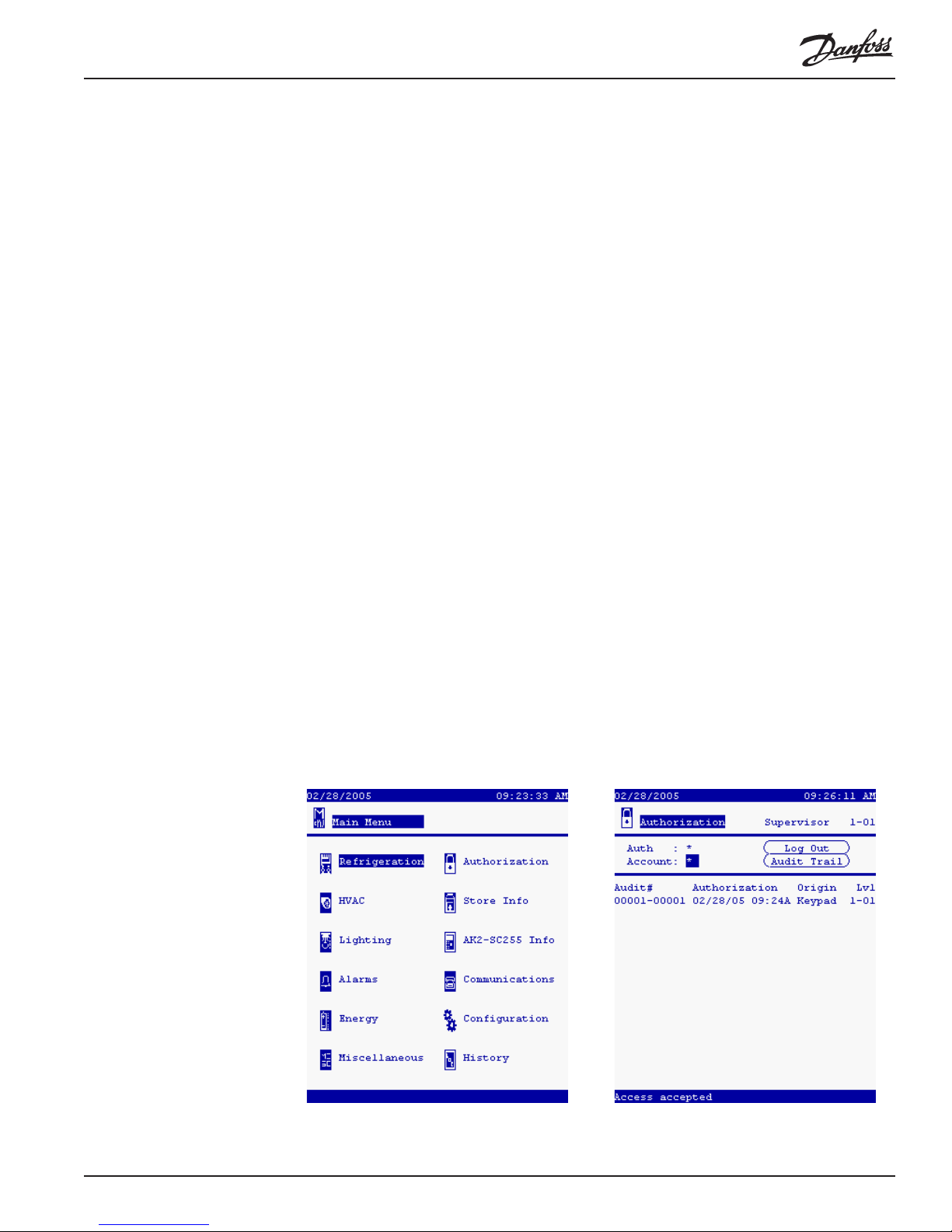
Authorization codes When the SC 255 is turned on for the first time, the Main Menu will appear as at left
below:
Before you can enter configuration information, you must select Authorization and
RS.8D.M1.22 AK2-SC 255 Reference Manual 1 1
Page 13

enter a valid authorization code and account code. Using the right arrow , move the
cursor to Authorization and press ENTER. The Authorization Menu will appear as
at right above, with the cursor in the Auth field.
When you have entered the access code and account number given to you by the
system owner, you will see the words Authorization accepted appear briefly in
reverse video at the very bottom of the screen. In the upper right, the screen will
show what the authorization level is.
After initial configuration, you will be able to make changes by several different
avenues, which are discussed in Chapter 5, “Using the System.”
Using menus To select from any SC 255 menu, first use the arrow keys to move the cursor to the
item you want, then press the ENTER key. You can use the EXIT key to retrace
your steps level by level.
Selection of Units
and Language Before using the system, you may wish to change the language used on the screens,
the units used for pressure and temperature, or the date and time format. These
settings will be for the local PC only, and will not af fect the displays of any SC 255 in
the system. To change the displayed units, select Store Information from the main
menu and then choose Units/Languages. In the Configuration Units/Languages
screen, select the language you want to see in the controller screens, then select
either psi or bar for pressure; either °F or °C for temperature; and either % or fc
(footcandles) for light level.
12 AK2-SC 255 Reference Manual RS.8D.M1.22
Page 14
1 - 2. Configuring Refrigeration
There are two “routes” you may need to navigate to begin configuring refrigeration.
One begins by selecting Refrigeration from the Main menu, and the other by
selecting Configuration.
Starting with a
Partially Configured
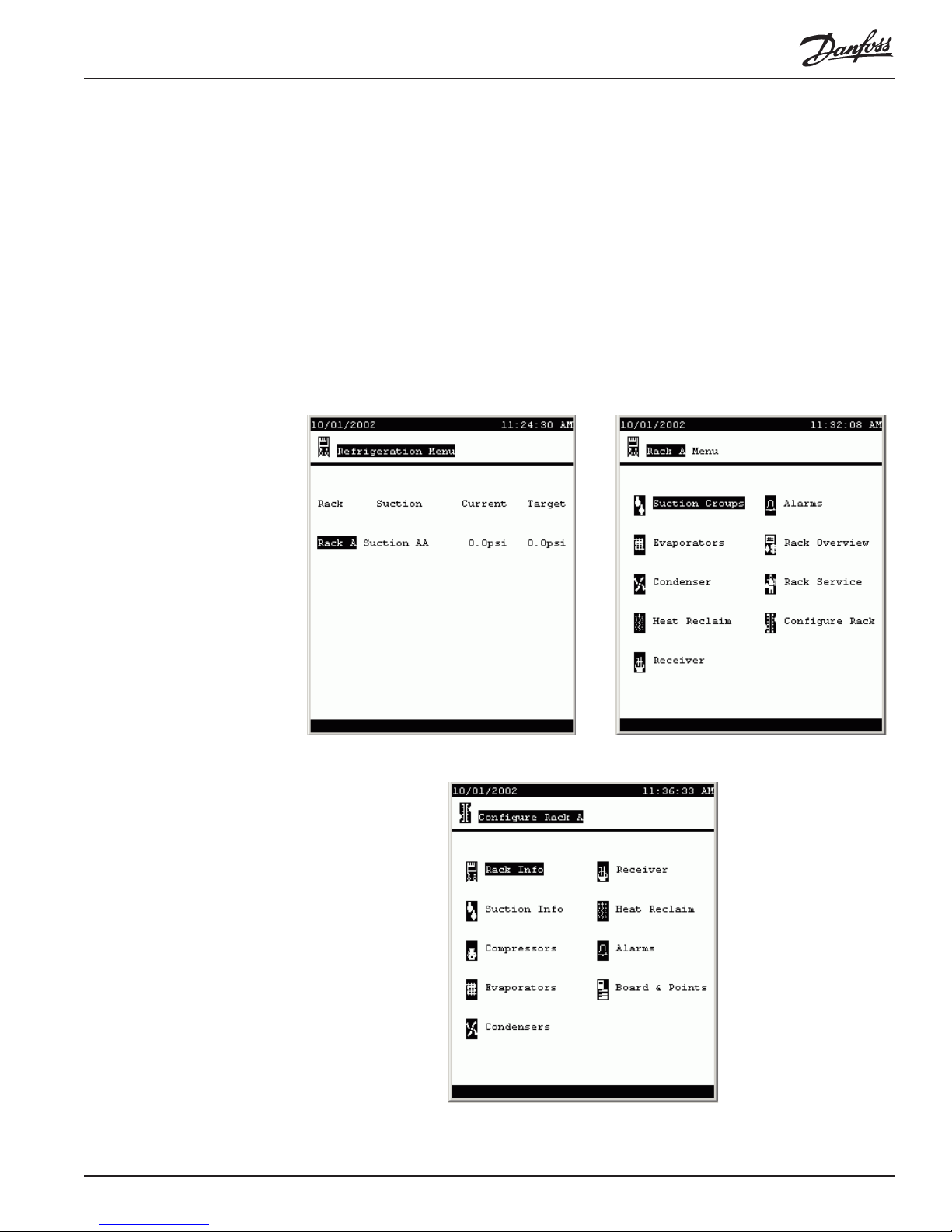
AK2-SC 255 If the AK2-SC 255 you are working with was supplied with a rack, the controller may
have been partially configured by the rack manufacturer. In that case, when you
select Refrigeration from the Main Menu, the SC 255 will display the Refrigeration
Menu (left). It lists the rack or racks that are partly configured. If you want to
change or add to the configuration of one of these racks, move the cursor to the rack
name and press ENTER. The Rack menu (right) will appear. In this example, only
one rack has been previously configured.
Select Configure Rack and the Configure Rack menu appears.
Now select the type of information you want to supply. We’ll cover a typical cat-
RS.8D.M1.22 AK2-SC 255 Reference Manual 1 3
Page 15
Starting with a
Completely
Un-configured
AK2-SC 255
egory right after we talk briefly about the other “route” configuration may take.
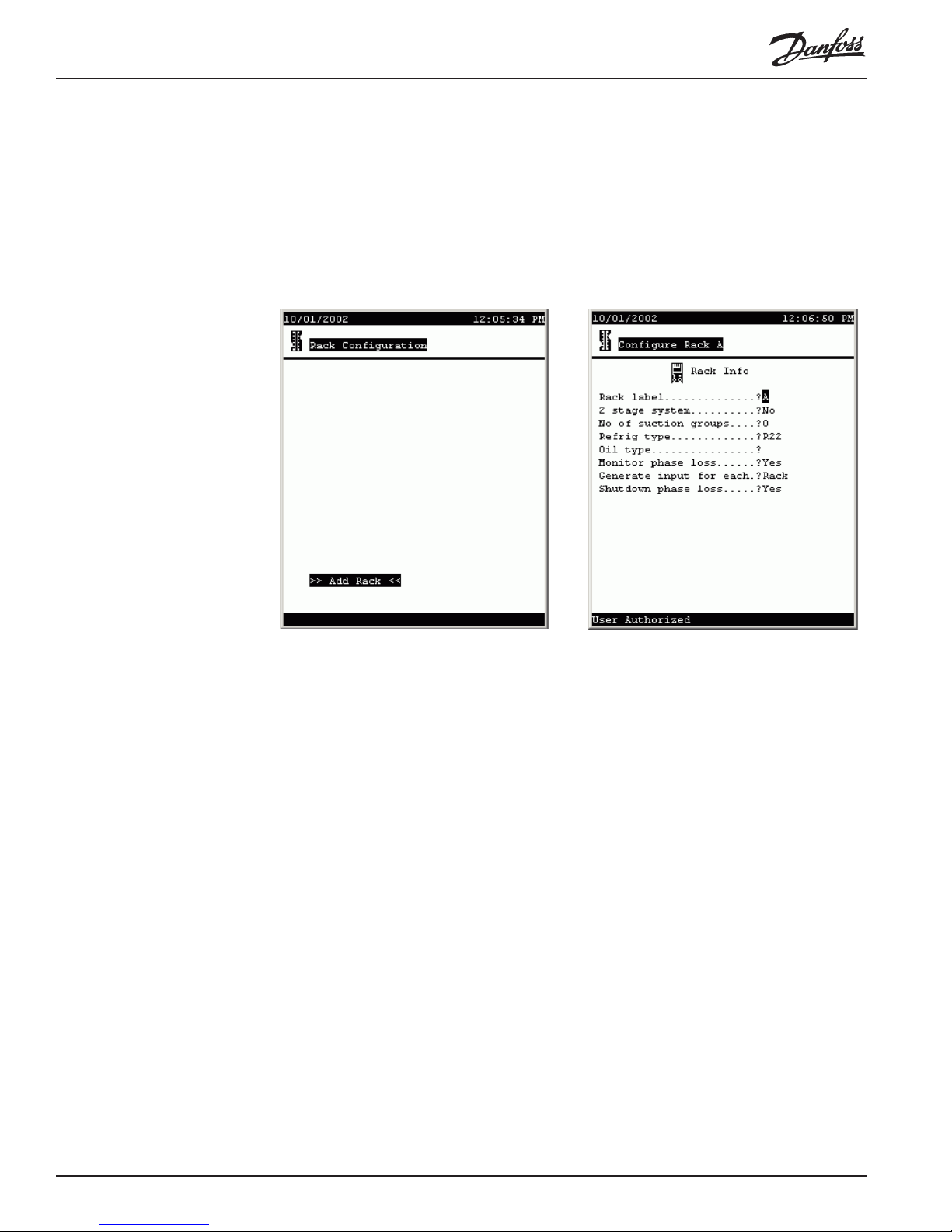
If the AK2-SC 255 you are working with has no refrigeration configuration at all,
select Refrigeration from the Main menu, and the Rack Configuration menu will
appear (left). The only selection which can be made from this screen is Add Rack.
Selecting Add Rack takes you to the Configure Rack, Rack Info screen (right).
Navigation and
making changes The Configure Rack A screen shown at right above has information fields that can be
changed by any user with a proper authorization code. To make changes, use the
arrow keys to move the cursor to the field you want to change
Entering numerals To enter numerals for a field like No of suction groups, use the numeral keys on the
controller keypad., then press ENTER.
Entering labels Labels are entries that you need to spell out. The Rack label field contains a label
one character in length. The Oil type field is also a label field, but it is 9 characters
long, allowing you to spell out a word or words indicating the oil type, for example,
“Mineral.”
To enter a label, place the cursor on the field, then press the +/- key. This action
toggles the function of the arrow keys so that the UP and DOWN arrows scroll
through the alphabet and all the other possible characters. Once the character you
want in that space appears, use the RIGHT arrow to move to the next space (when
the field has more than one space). Again, use the UP and DOWN arrows to reach
the character you want. When all the characters in the field are as you want them,
press ENTER to save the entry.
Constrained fields The Rack label field is a constrained field. It will only accept an upper case letter,
even though lower case letters appear as you scroll through the characters. The No
of suction groups field is also constrained. It will only accept a single numeric
character from 0 to 5, because a single AK2-SC 255 can control up to 5 suction
14 AK2-SC 255 Reference Manual RS.8D.M1.22
Page 16
Selecting from list boxes
groups. Note that in the case of this particular field, entering a 0 (zero) will pop up a
warning box letting you know that a zero response here will eliminate the suction
groups already configured and will delete all information stored for the rack; you will
be asked to confirm the entry.
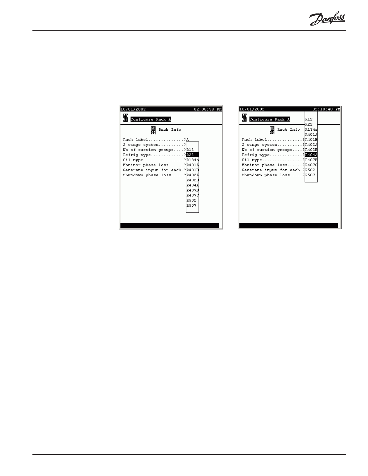
The next pair of illustrations shows how the controller uses list boxes.
The list box appears, as shown at left above, when you move the cursor to the field
and then press the +/- key (or, at your PC, right click). Then, using the UP and
DOWN arrow keys, you can move the cursor to make a selection. In the example at
right, R404A has been chosen. The cursor actually stayed in the same position, but
the “window” moved.
When you have put the list box’s cursor on the selection you want, press ENTER to
save your selection.
Some list boxes contain only two choices (for example, Yes and No in the Monitor
phase loss field). Some may contain many choices. When that is the case, one of the
lines in the box will contain three dots. When the cursor is moved to the three dots,
additional choices appear.
Now that we understand navigation and making changes, we can go on to a discussion of each of the configuration screens.
Configuring Rack Info In the rack Info screens, the following are the fields, and their possible contents:
Rack label (Upper case letters, A to Z) The “name” of the rack.
2 stage system (List box: Yes, No)
No of suction groups (0 to 5) Note that for a rack with existing configura-
tion, entering and confirming a 0 will cause deletion of
all existing rack information.
Refrig type (List box) The kind of refrigerant.
Oil type (9 characters, not constrained)
Monitor phase loss (List box: Yes, No) Whether or not there will be a
RS.8D.M1.22 AK2-SC 255 Reference Manual 1 5
Page 17
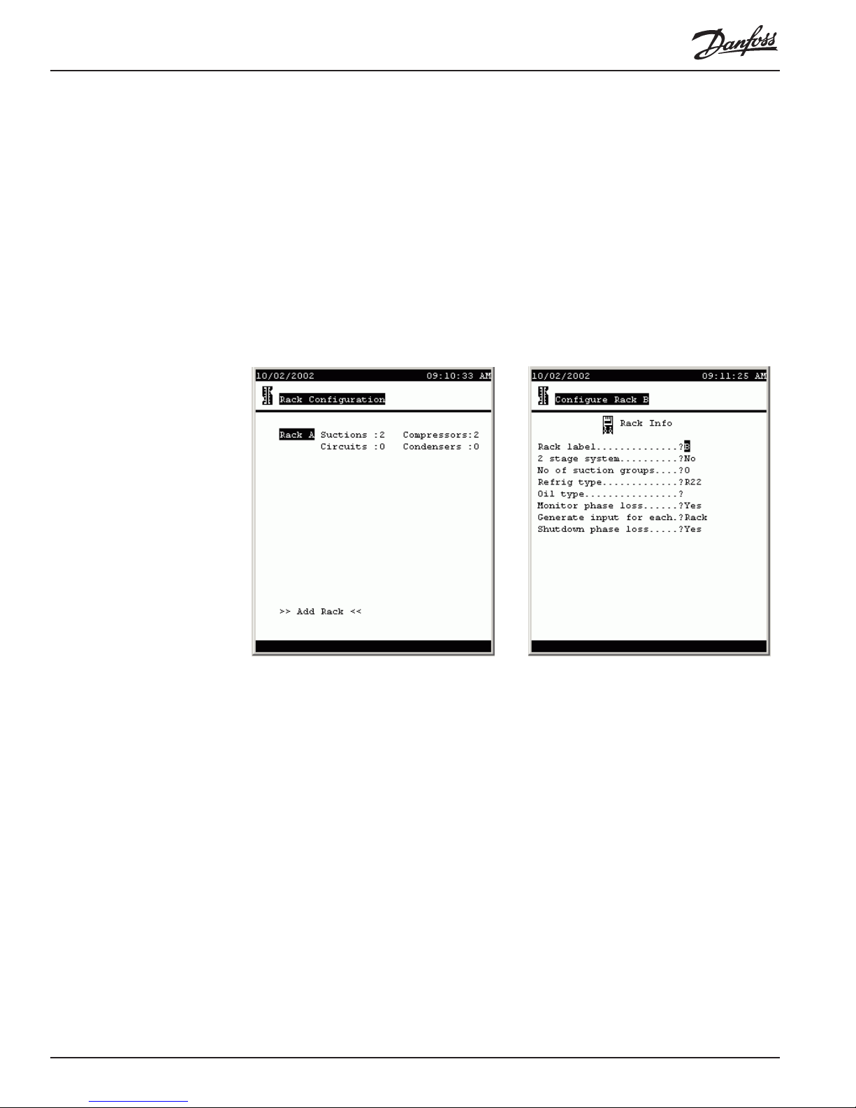
digital input from a phase loss monitor.
Generate input for each [appears only after a Yes answer to the preceding
question] (List box) Whether there is a phase loss
input for each rack or each suction group.
Shutdown phase loss [appears only after a Yes answer to the Monitor phase
loss question] (List box: Yes, No)
When all of the items on the Rack Info screen have been configured, press MENU to
return to the Main Menu.
Adding a Rack There is only one way to add a rack. From the Main Menu select Configuration,
then Refrigeration, and the Rack Configuration screen appears. At the bottom left of
the screen are the words >> Add Rack<<. Move the cursor there and press
ENTER. A new Rack Info screen will appear.
Notice that the Rack Label field contains the letter B by default, since the previously
configured rack was rack A. You can change the default label if you want.
Configuring
Suction Info T o configure a suction group, press MENU to return to the Main Menu, then select
Configuration, then Refrigeration. The Rack Configuration screen appears as at
left above. Select the rack and a Configure Rack menu appears (as at left below) .
16 AK2-SC 255 Reference Manual RS.8D.M1.22
Page 18
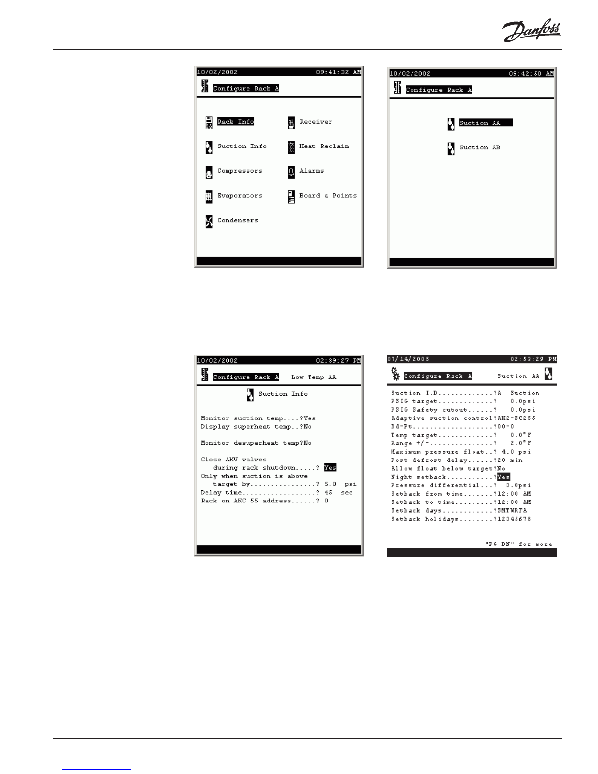
Once at suction configuration menu shown at right above, select the suction group you
want to configure and press ENTER. The Suction Info screen for that group will
appear as at right below. As you configure, questions may appear that are not
included on the default screen. The screen at left below shows all the possible lines
revealed.
The fields and their contents are as follows:
Suction I.D. (2 label fields: the first is a list box: A to Z; the second
PSIG target (-50.0 to 500.0) The pressure that the controller will
RS.8D.M1.22 AK2-SC 255 Reference Manual 1 7
is 9 characters not constrained) This is the identification you wish to assign to the suction group. The entry
will modify the screen title. For example, if you enter a
B in the first field and Low Temp in the second, the
right portion of the screen title for the configuration
and status screens for this group will read Low Temp
AB.
maintain, subject to capabilities of mechanical equip-
Page 19

ment, for this suction group.
PSIG Safety cutout (-50.0 to 150.0) The gauge pressure at which the
controller will stop the compressors in this suction
group.
Adaptive suction control (List box)
None: No adaptive suction control.
AK2-SC 255: Target pressure is adjusted based on
discharge temperature of a single fixture.
AKC 16x: Adaptive control of individual evaporators
by an AKC 164 or AKC 161 Smart Case Controller.
Sensor: Target pressure is adjusted based on any
sensor on the AKC 55 I/O network
Dynamic: The SC 255 analyzes the performance of
every case on each individual circuit, and adjusts target
pressure intelligently by using the case sensor that
varies most from the setpoint.
Bd-Pt (For the first group, to the left of the hyphen, 01 to 99;
for the second group, to the right of the hyphen, 1 to 8).
The board and point address of the fixture sensor used
by the adaptive control algorithm. (Does not appear
when dynamic adaptive control is selected.) Note that
board and point numbers use a different format with
AK2 modules. See the AK2 I/O user manual for more
information.
Temp target (-50.0 to 100.0) The temperature that the adaptive
control algorithm will seek to maintain in the fixture.
(Does not appear when dynamic adaptive control is
selected.)
Range +/- (0.0 to 100.0) The dead band around the temperature
target. As long as the fixture temperature remains in
this range, the suction pressure target will not be
modified. (Does not appear when dynamic adaptive
control is selected.)
Maximum pressure float (0 to 99.9) The number of psig that the adaptive
algorithm will be allowed to cumulatively add or
subtract from the suction pressure target.
Post defrost delay (0 to 60) The number of minutes after termination of
defrost during which there will be no target adjustment.
(Does not appear when Sensor is selected as the type
of adaptive control.)
Allow float below target (List box: Yes, No) Determines whether or not the
adaptive algorithm will be allowed to adjust suction
pressure below the target if fixture temperature is
above target temperature + range.
Night setback (List box: Yes, No) Determines whether or not suction
pressure will be offset according to a schedule to be
specified in the following lines.
Setback from time (Time field) The start time for night setback.
Setback to time (Time field) The ending time for night setback.
Setback days (Days selection field) The days on which night setback
will be effective.
18 AK2-SC 255 Reference Manual RS.8D.M1.22
Page 20
Setback holidays (Holidays selection field) The holiday numbers on
which night setback will occur. Holiday numbers are
defined in Store Info configuration.
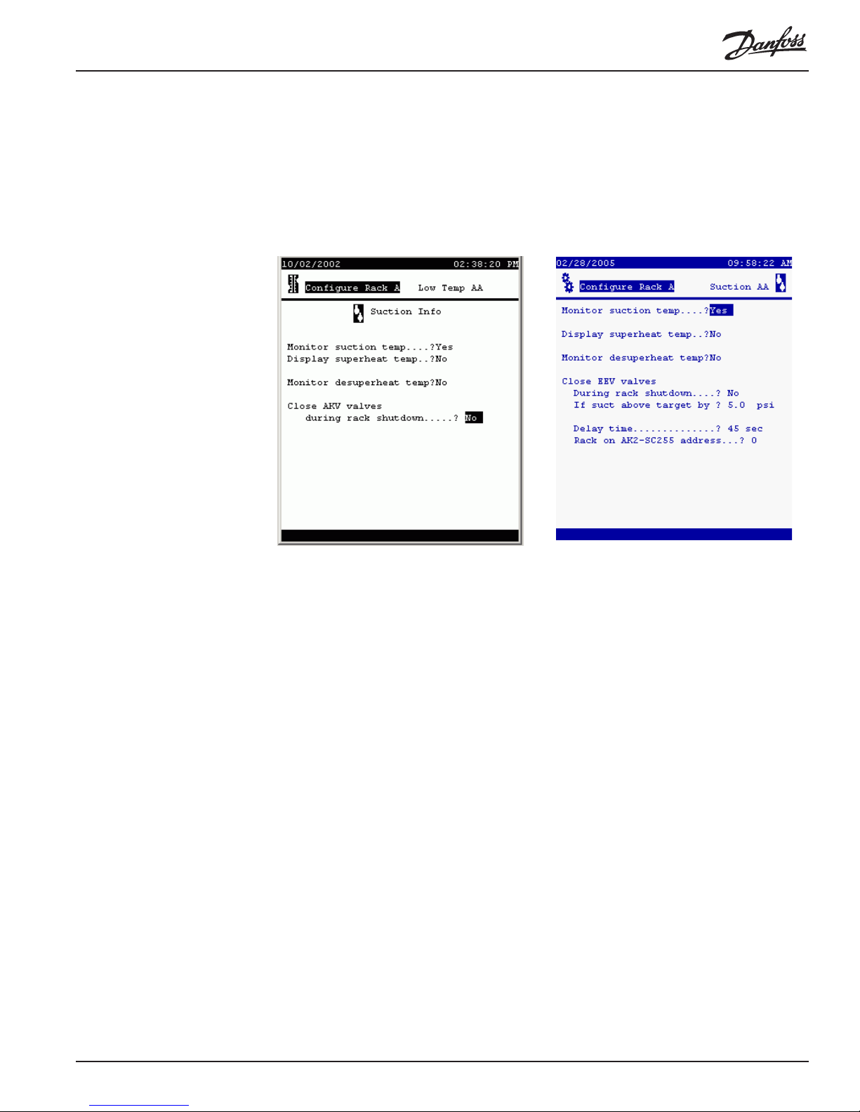
At the bottom right of the Suction Info screen are the words “PG DN” for more.
Use the controller’s PG DN key to reach the next screen; shown at left is the default
screen in which not all the questions and fields appear; the screen on the right shows
all the fields.
Configuring
two-stage systems
The fields and their contents are as follows:
Monitor suction temp (List box: Yes, No)
Display superheat temp (List box: Y es, No)
Monitor desuperheat temp (List box: Yes, No)
Close EEV valves during
rack shutdown (List box: Yes, No)
If suct above target by (0 to 999.9) Number of psig above target when AKV
valves will be closed during rack shutdown.
Delay time (0 to 45) Number of seconds after suction pressure
reaches target + the number specified in the preceding
field that AKV valves will be closed.
Rack on AK2-SC 255 address
(0 to 15) The address of the SC 255 controlling the
rack that serves these EEVs.
Press EXIT to return to the Configure Rack Menu and continue refrigeration configuration.
and de-superheaters If (and only if) a rack is configured as a two-stage system, the
suction configuration for each suction group will include a special page for the low
side. The screen looks like this:
RS.8D.M1.22 AK2-SC 255 Reference Manual 1 9
Page 21
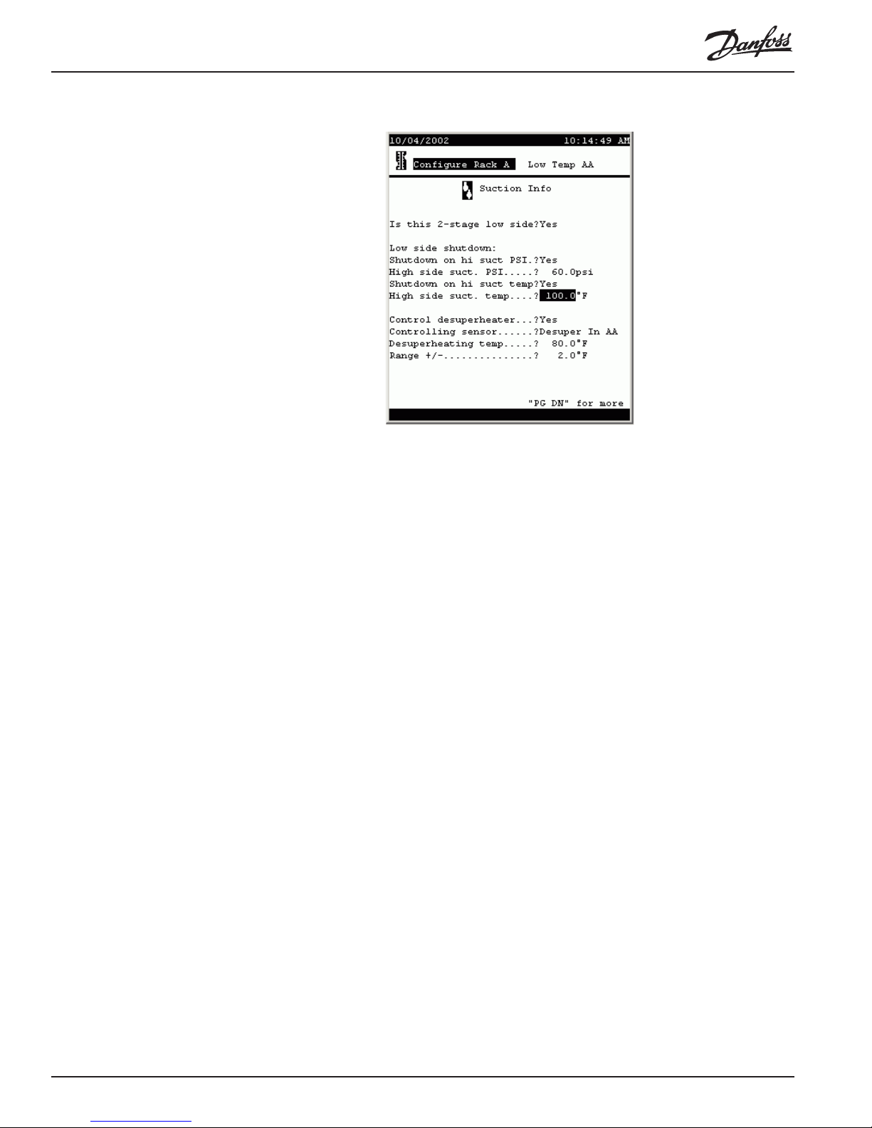
The fields and their contents are as follows:
Is this 2-stage low side (List box: Yes, No) Is this the low side of the two?
Low side shutdown:
Shutdown on hi suct PSI (List box: Yes, No) Whether or not to shut down the
low side compressors when high side reaches a
specified suction pressure.
High side suct. PSI (-99.0 to 200.0) The high side suction pressure at
which the low side will be shut down.
Control desuperheater (List box: Yes, No) Whether or not de-superheater
control is implemented on this rack.
Controlling sensor (List box:)
Desuper In AA: Control is based on a sensor moni-
toring the liquid in temperature at the de-superheater.
Desuper Out AA: Control is based on a sensor
monitoring the liquid out temperature at the de-superheater.
Suction Temp AA: Control is based on a sensor
monitoring suction temperature.
Desuperheating temp (-50.0 to 200.0)
Range +/- (1.0 TO 10.0)
Configuring
compressors To begin configuring compressors, select Compressors from the Configure Rack
menu. The first page of the screen looks like this:
20 AK2-SC 255 Reference Manual RS.8D.M1.22
Page 22
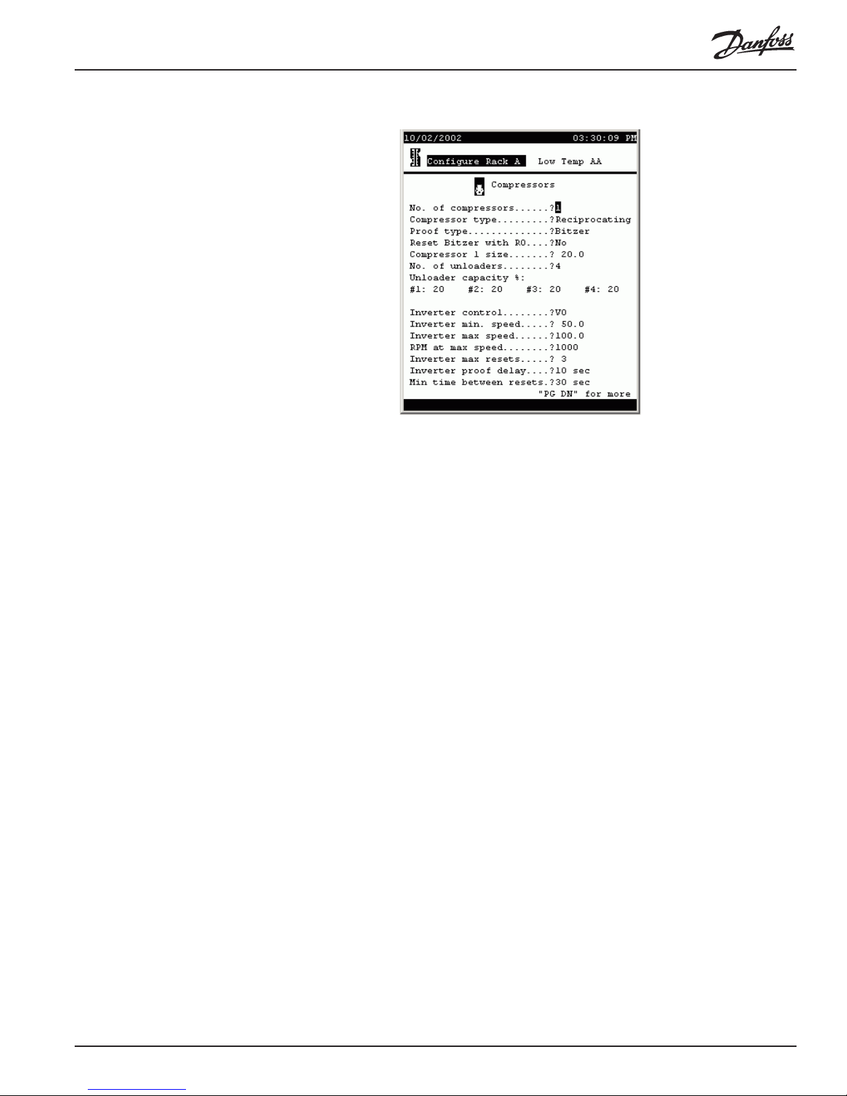
The fields and their contents are as follows:
No. of compressors (0 to 9)
Proof type (List box:) The means by which proof of compressor
operation is monitored.
None: No proof
OI: A digital input (on-of f input) is used for proof.
CT: A current transformer is used for proof.
Bitzer: Proof is obtained from a Bitzer electronic
module.
Reset Bitzer with RO (List box: Yes, No) Whether or not Bitzer compres-
sors are reset by a digital output (relay output).
Compressor size (1 to 500) The capacity of the compressor.
No. of unloaders (0 to 4) The number of compressor unloader stages.
Unloader capacity % (1 field per unloader: 0-99) The percent of capacity
shed by the respective unloader.
Inverter control (List box:) Type of variable speed control.
None: No inverter control
VO: An inverter is controlled by an analog output
(variable output).
VLT: A Danfoss VLT adjustable frequency drive is
used.
Inverter min. speed (1.0 to 150.0) The minimum percentage of rated
speed at which the inverter will run the compressor.
Inverter max speed (1.0 to 150.0) The maximum percentage of rated
speed at which the inverter will run the compressor.
RPM at max speed (1 to 9999) The RPM that will be displayed at maxi-
mum percentage.
Inverter max resets (0 to 10) The number of resets after which the
inverter will be put in override.
Inverter proof delay (0-99) The number of seconds without proof that must
elapse before an inverter reset occurs.
Min time between resets (0 to 99) The number of seconds that must elapse
before second and subsequent inverter resets.
RS.8D.M1.22 AK2-SC 255 Reference Manual 2 1
Page 23
Configuring other
compressors in the
suction group Paging down, you will find a page for each compressor in the suction group. These
subsequent screens will have only questions pertaining to the individual compressors,
not the rack questions found at the top of the screen for compressor number one.
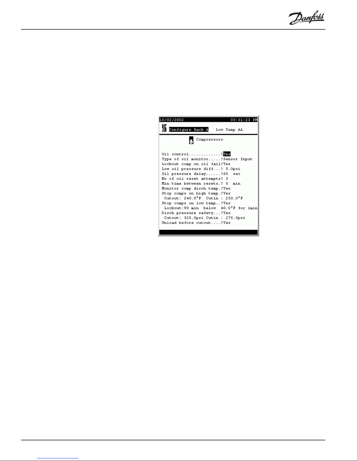
Compressor oil and
safety information After basic operating data has been entered for all compressors, paging down will
produce this screen:
The fields and their contents are as follows:
Oil control (List box: Yes, No) Whether or not oil control is
implemented.
Type of oil monitor (List box:)
Sensor Input: An analog input (sensor input) is used
to monitor oil pressure.
On/Off: A digital input (on-off input) is used to monitor
an oil pressure switch.
Copeland: A Copeland oil monitor is used.
Lockout comp on oil fail (List box: Yes, No) Whether or not compressors will
be locked out when an oil failure is detected.
Low oil pressure diff (0 to 50) The oil pressure differential, when an analog
sensor input is used, that will cause compressor
shutdown.
Oil pressure delay (0 to 255) When an analog sensor is used, the number
of seconds after oil failure is detected before compressors are reset.
No of oil reset attempts (0 to 10) After oil failure is detected, the number of
reset attempts before compressors are locked out.
Min time between resets (0 to 60) After a reset (whether successful or not) the
number of minutes that must elapse before another
reset attempt.
Monitor comp disch temp (List box: Yes, No) Whether or not compressor
discharge temperature is monitored.
22 AK2-SC 255 Reference Manual RS.8D.M1.22
Page 24

Stop comps on high temp (List box: Yes, No) Whether or not compressors are to
be shut down on high discharge temperature.
Cutout (0.0 to 300.0) The discharge temperature at which
compressors are to be cut out.
Cutin (0.0 to 300.0) After a cut-out on high discharge
temperature, the discharge temperature at which
compressors are to be cut in.
Stop comps on low temp (List box: Yes, No) Whether or not comrpessors are to
be cut out on low discharge temperature.
Lockout (0 to 255) The number of minutes that must elapse
before a lockout on low discharge temperature. (See
note on next field).
below (0 to 300) The temperature that discharge must be
below for the time specified in the preceding field
before lockout on low discharge temperature occurs.
Note: If discharge temperature rises above the
setpoint, the time for lockout will restart from zero.
Disch pressure safety (List box: Yes, No) Whether or not comrpessors are to
be cut out on high discharge pressure.
Cutout (0.0 to 500.0) The discharge pressure at which com-
pressors are to be cut out.
Cutin (0.0 to 500.0) After a cut-out on high discharge
pressure, the discharge pressure at which compressors
are to be cut in.
Unload before cutout (List box: Yes, No) Whether or not comrpessors are to
be unloaded before being cut out.
Neutral Zone
control The next page of compressor configuration deals with neutral zone control. Basically,
neutral zone control acts to bring the current pressure toward target pressure more
quickly the greater the difference between the two. The screen looks like this:
The default settings are as shown in the screen above. It is recommended that the
values not be changed without a thorough understanding of the algorithm. A thorough
explanation of neutral zone control is available as an appendix to this manual.
RS.8D.M1.22 AK2-SC 255 Reference Manual 2 3
Page 25
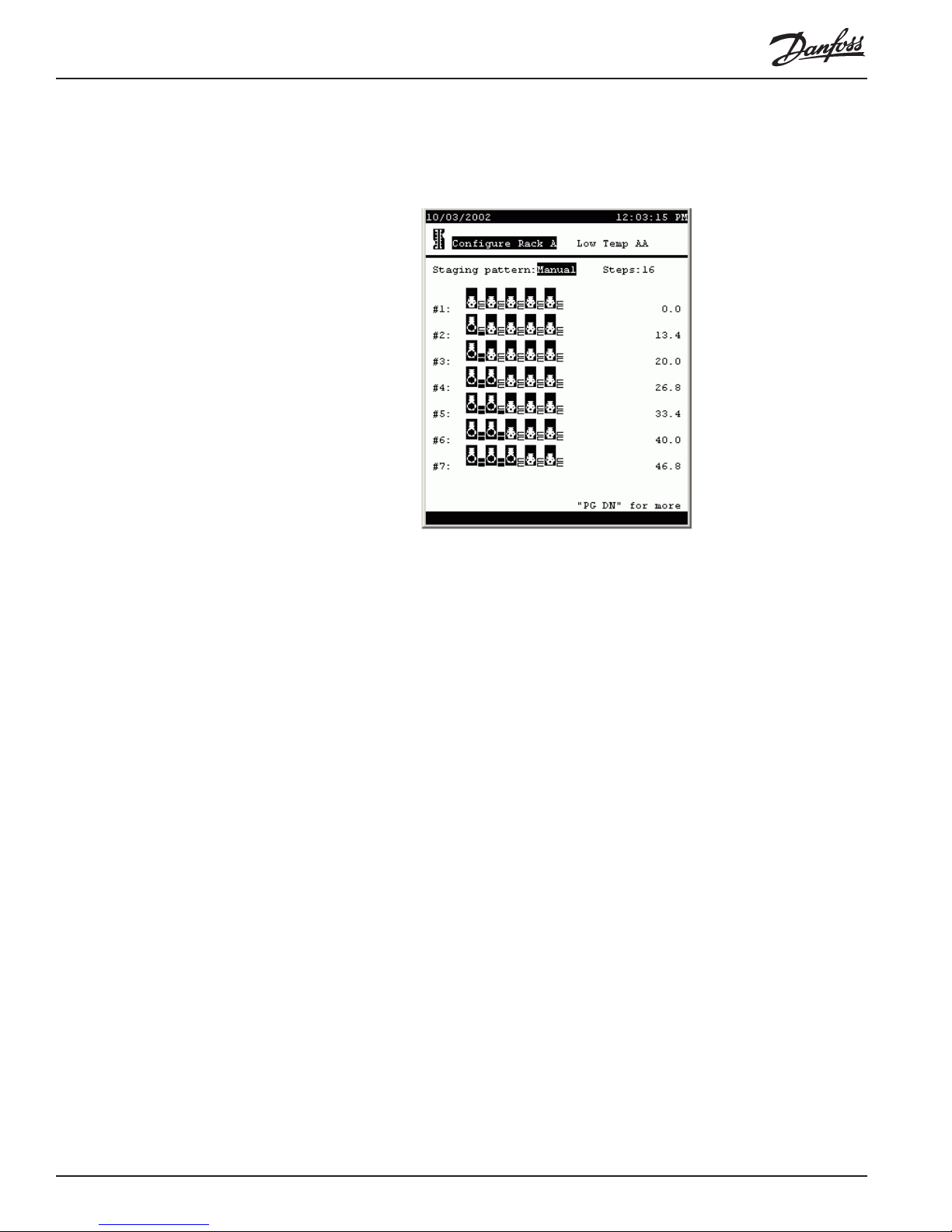
Compressor capacity
staging patterns Paging down from the neutral zone screen reveals the compressor staging pattern
screen:
In the default screen, the staging pattern is Auto, for automatic staging, and there is
no selection for Steps. The controller will stage rack capacity in the smallest steps
possible from lowest total capacity to highest, automatically selecting the compressors
combination to run for each stage (based on the the configured compressor capacities
available on the rack).
When there are a large number of steps, manual staging can be used to eliminate
needlessly small steps and compressor cycling.
T o use manual staging, select Manual from the pattern list box, then specify the
number of steps you want. The display that results will show a row compressor icons
for each stage. A compressor’s unloaders are represented by the small rectangles to
the right of the compressor icon.
In the sample screen, compressors are all 20 HP and each has 2 unloaders. Each
unloader is 33% of compressor capacity. These settings were determined on the
configuration page for each compressor.
Stage #1 is fixed at zero capacity and cannot be changed.
To change stage #2 or any higher stage, move the cursor to a compressor icon and
press enter. You will notice that the “piston” in the icon moves. When it is up, the
compressor is on. If there are unloaders on a compressor, subsequent clicks on the
compressor icon will turn the unloader steps on, one at a time. The small rectangles
will change color to indicate that the step is on. When all steps are on for a compressor, the next click on the icon will turn everything off.
As you change a stage’s capacity, the number in the right column of the screen will
24 AK2-SC 255 Reference Manual RS.8D.M1.22
Page 26
change for that stage, giving the total horsepower you have selected for that stage.
You can change the number of steps at any time.
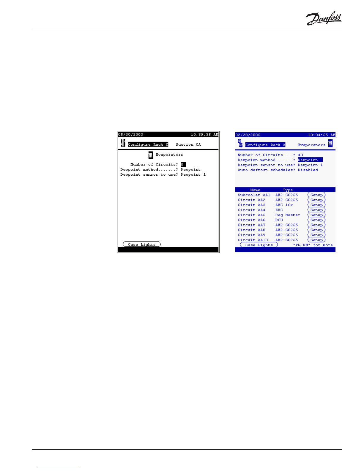
Configuring
evaporators To begin configuration of evaporators, return to the Configure Rack menu and select
Evaporators. Or, from the Main Menu (which you can always reach with the
MENU key) select Configuration, Refrigeration, the particular rack, and Evaporators.
The evaporator menu will initially look like as on the left below , with no evaporators
listed, but as soon as you enter a number in answer to the top question, and select
from the Type list box for some of the evaporators, the screen will look something
like the one at right:
There are six kinds of evaporator control shown. In this manual, we will discuss the
configuration of SC 255 circuits and AKC 16x circuits. For the other types of evaporators, please see the manuals on the individual controllers. In the future, when a
Danfoss Case Control manual is created, we will remove the AKC 16x material from
this manual.
First, the changeable fields in the Evaporator Menu (shown above on the right) are as
follows:
Number of circuits (1 to 40) The number of circuits in the suction group.
Dewpoint method (List box:)
Dewpoint: A dewpoint sensor or sensors will be used
for anti-sweat control.
Calc Dewpoint: Dewpoint for anti-sweat control will
be calculated using the values of relative humidity and
temperature sensors.
Dewpoint sensor to use [If Dewpoint has been selected](List box:) How anti-
sweat control dewpoint will be determined if a
dewpoint sensor is used.
Min Dewpoint: The lowest-reading of a number of
dewpoint sensors will be used.
Max Dewpoint: The highest-reading of a number of
RS.8D.M1.22 AK2-SC 255 Reference Manual 2 5
Page 27

dewpoint sensors will be used.
Average: The average of a number of dewpoint
sensors will be used.
Dewpoint 1: A single dewpoint sensor will be used for
control.
[others]: Other dewpoint sensors, if they exist, will be
listed also.
Humidity sensor to use: [If Calc Dewpoint has been selected](List box:) How
dewpoint will be determined if a humidity sensor is
used.
Min Humidity: The lowest-reading of a number of
humidity sensors will be used.
Max Humidity: The highest-reading of a number of
humidity sensors will be used.
Average: The average of a number of humidity
sensors will be used.
Inside RH 1: A single humidity sensor will be used
for control.
[others]: Other humidity sensors, if they exist, will be
listed also.
Auto defrost schedules (List box: Disabled, Enabled)
Enabling this option will cause the controller to suggest
a defrost schedule based on the following two additional questions.
Maximum concurrent electric defrosts
[Appears only if Auto defrost schedules is enabled]
(0 to 20) The number of electric defrosts that can be
underway concurrently .
Include dripdown time [Appears only if Auto defrost schedules is enabled]
(List box: Yes, No) Answering “Yes” will cause a drip
down period to follow defrost before refrigeration is
allowed. The length of the drip down period will be that
specified by the user when defrost schedules are autoconfigured.
Type (List box:) [for each individual evaporator] the type of
evaporator control.
AK2-SC 255/SUBC: A subcooler controlled as an
SC 255 circuit.
AK2-SC 255: The circuit is controlled by the SC
255’s algorithms.
AKC 16x: Control is at the fixture by AKC 161 or
AKC 164 Smart Case Controllers.
EKC: Control is at the fixture by EKC 201 controllers.
Deg Master: Control is at the fixture by Hill/PHOENIX Degree Master controllers.
DCU: Control is at the fixture by DCU case controllers.
Case lights button In the lower left corner of the screen body is a button, CASE LIGHTS. Selecting this
button and pressing ENTER will open the configuration screen for a case lights
26 AK2-SC 255 Reference Manual RS.8D.M1.22
Page 28
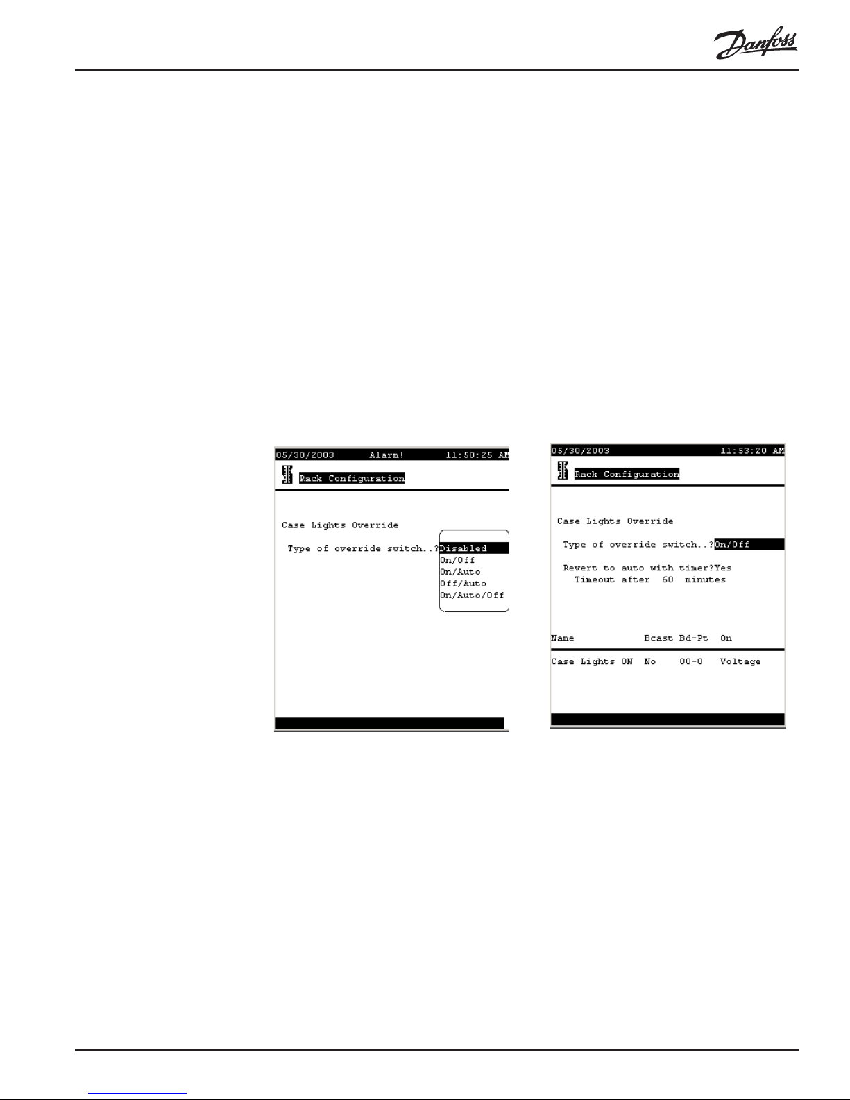
override switch. The screen at left below appears (with the list box closed) when the
CASE LIGHTS button is activated. The fields on the screen and their meanings are
as follows:
Type of override switch (List box)
Disabled: There is no override switch configured.
On/Off: A two-position override switch allows the
lights to be switched on or off.
On/Auto: Choices are ON or automatic operation.
Off/Auto: Choices are OFF or automatic operation.
On/Auto/Off: All three choices are available with a
three position switch being installed.
Depending upon configuration and the equipment
present, dewpoint for anti-sweat control can be read
from a dewpoint sensor, or it can be calculated using
the values of relative humidity and temperature sen-
sors.
Configuring AK2-SC 255
subcooling circuits When subcooler valves are controlled directly by the SC 255 (that is, when an AKC
RS.8D.M1.22 AK2-SC 255 Reference Manual 2 7
Page 29
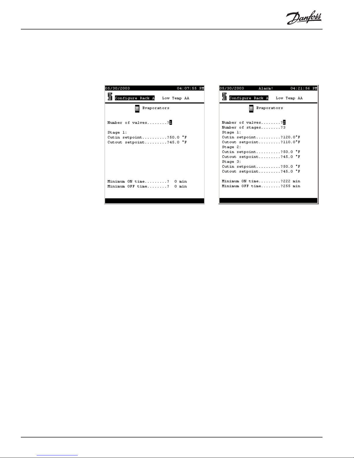
165 Subcooling Controller is not used) configuration begins by selecting AK2-SC 255/
SUBC in the Type column for the circuit on the Evaporator Menu, then moving the
cursor to the word Setup for that evaporator and pressing ENTER. A screen like the
one at left below will appear. The same screen with all its fields revealed appears as
at right.
The fields are as follows:
Number of valves (0 to 2) The number of valves used for subcooling.
Number of stages (1 to 3) With one valve, there can be only 1 stage of
subcooling. W ith two valves, there can be two stages
(one valve open or two). If there are two valves
feeding subcoolers of different capacities, then there
can be three stages (only valve 1 open, only valve 2
open, or both valves open).
Cutin setpoint (0.0 to 120.0, each stage has a separate setpoint) The
temperature at which the subcooling stage will become
active. Temperature is measured by a sensor at the
liquid outlet of the subcooler.
Cutout setpoint: (0.0 to 110.0, each stage has a separate setpoint) The
temperature at which the subcooling stage will shut
down.
Minimum ON time (0 to 255) The minimum time in minutes each stage
must remain active after being cut in.
Minimum OFF time (0 to 255) The minimum time in minutes each stage
must remain off after being cut out.
Configuring
AK2-SC 255
refrigeration circuits If there is not a distributed controller at the fixture (AKC 161, AKC 164, Degree
Master, or DCU), refrigeration can be controlled directly by the AK2-SC 255. Configuration of such circuits starts by selecting AK2-SC 255 in the Type column for the
circuit on the Evaporator menu, then moving the cursor to the word Setup for that
evaporator and pressing ENTER. A screen like the one at left below will appear. The
28 AK2-SC 255 Reference Manual RS.8D.M1.22
Page 30
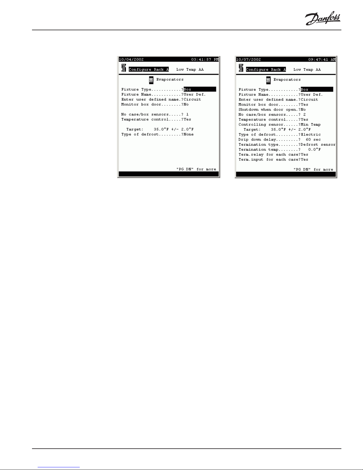
same screen with all its fields revealed appears as at right.
The fields are as follows:
Fixture Type (List box) Various types of fixture can be selected:
box, multi-deck, single deck, service, etc.
Fixture Name (List box) There is a large selection of common fixture
names for each of the fixture types that can be selected above, and there is a selection User Def. After
making that selection, you will be able to spell out your
own name on the following line.
Enter user defined name (Label) The name of a user-defined fixture. Any of
the characters in the AK2-SC 255 character set can be
used, including upper and lower case letters and
symbols.
Monitor box door (List box: Yes, No) Whether or not a box door switch
will be monitored (appears for boxes only).
Shutdown when door open (List box: Yes, No) Whether or not to shut down
refrigeration when the box door is open.
No case/box sensors (0 to 15) The number of sensors in this fixture or
circuit.
Temperature control (List box: Yes, No) Whether or not temperature contol
will be used.
Controlling sensor (List box:)
Min Temp The lowest of the sensors in the fixture or
on the circuit will be used for temperature control.
Max Temp The highest of the sensors in the fixture
or on the circuit will be used for temperature control.
Average The average of all the sensors in the fixture
or on the circuit will be used for temperature control.
[circuit names] The name of each sensor will be
listed, and any can be selected. That sensor , then, will
be used for temperature control.
Target: (-99.0 to 150.0 [target] 1.0 to 20.0 [range] The target
RS.8D.M1.22 AK2-SC 255 Reference Manual 2 9
Page 31

temperature and the range about the target, used in
temperature control. The range is the amount above or
below target that the actual sensor temperature is
allowed to change before a control action is taken.
Type of defrost (List box) Various types of defrost can be chosen:
None, Hot Gas, Time Off, Air, or Electric.
Drip down delay (1 to 600) The number of seconds that refrigeration
will remain off after termination of defrost.
Termination type [Defrost time settings made on the pages that follow
must also be considered. If a minimum defrost time
is used, that time must elapse regardless of the
settings made on this page. If a defrost duration is
specified, either that time must elapse OR the
requirements set on this page must be satisfied for
defrost to terminate.]
(List box) Various termination strategies are listed.
Defrost sensor There is a dedicated defrost tem-
perature sensor that will be used to terminate defrost.
Disch air snsr The fixture discharge air sensor will
be used to terminate defrost at a set temperature.
On/Off Input An electrical switch (such as a Klixon
is wired to a digital input (on-off input) and will be used
to terminate defrost.
None: Defrost is terminated strictly on time.
Hot gas return: Hot gas defrost is terminated when a
return air sensor reaches a setpoint.
Termination temp (-99.0 to 200.0) The defrost temperature sensor value
at which defrost will terminate.
Term.relay for each case (List box: Yes, No) Whether or not there is a termina-
tion relay for each case.
Term.relay for each case (List box: Yes, No) Whether or not there is a termina-
tion input each case.
®
Paging down produces the next page:
30 AK2-SC 255 Reference Manual RS.8D.M1.22
Page 32

[Defrost time settings made on this and the following pages work with the
termination settings on the preceding page. If a minimum defrost time is used,
that time must elapse AND the settings for defrost termination temperature or
switch must be satisfied. If a defrost duration is specified, either that time must
elapse OR the requirements set on this page must be satisfied for defrost to
terminate.]
The fields are as follows:
Use min defrost time (List box: Yes, No) Whether or not minimum defrost
time will be used.
Minimum defrost time (1 to 180) The number of minutes defrost must be on
before termination.
Antisweat control (List box: Yes, No) Whether or not anti-sweat heaters
will be controlled by the AK2-SC 255. When you
configure an evaporator and answer Yes to the antisweat control question, a relay output is created which
is then wired to a relay controlling the anti-sweat
heaters. The name of the relay output will be
“Antisweat” + the name of the evaporator or circuit,
then the rack, suction group, and circuit number (for
example, Produce AA3).
ON when dewpoint above (0.0 to 100.0) The dewpoint above which anti-sweat
heaters will be on constantly.
Cycle above dewpoint (0.0 to 100.0) The dewpoint above which anti-sweat
heaters will be cycled. Cycling will occur unless the
dewpoint rises above the setpoint.specified in the
previous line.
Antisweat cycle time (2 to 999) The time interval on which anti-sweat
cycling is based.
Fan control (List box: Yes, No) Answer Yes if fans are to be
controlled during and after defrost. If you answer No,
fans will run continuously during both refrigeration and
defrost.
Fans on during defrost (List box: Yes, No) The answer determines whether or
not fans will run during defrost.
Stop fan on high temp (List box: Yes, No) Whether or not fans are to be
stopped when temperature rises above a setpoint to be
specified in the next line.
Fan stop temp (-58.0 to 99.9) The temperature at which fans will be
stopped.
Fan delay control (List box: Yes, No) A Yes answer will cause fans to
remain off after defrost termination for a specified
period of time or until a specified temperature is
reached. The time or temperature is determined by the
next two questions.
Start fan on time (List box: Yes, No) The answer determines whether or
not fan delay ends after a specified time.
Delay time (0 to 20) The number of minutes before fans start
after defrost terminates.
RS.8D.M1.22 AK2-SC 255 Reference Manual 3 1
Page 33

Fan starting temp (-58.0 to 99.9) The temperature at which fans will be
started after fan delay, if fans are not started on time.
Monitor door position (List box: Yes, No) Whether or not an alalog sensor
input is created to monitor the position of the door. This
sensor reads in percent and will be seen on the status
screen for the circuit. An alarm can be based on it.
Configuring Defrost Defrost configuration begins on the next setup page for an evaporator circuit.
The fields are as follows:
No of defrosts per day (0 to 12) The number of defrosts each day.
Defrost duration (1 to 180) The number of minutes after which defrost
will terminate, if termination has not occurred on a
setting configured in the previous screen. Often called
“fail-safe” defrost time.
Defrost start time (time of day; one field for each of the number of
defrosts configured in the first line of the screen) The
time each defrost will initiate.
Allow defrost skip (List box: Yes, No) When Yes is selected, The SC 255
has the ability to determine, based on analysis of
current and accumulated data, to determine if each
defrost is needed. When a defrost is not needed, it is
not initiated, thus reducing energy cost and enhancing
product life.
Min time between defrost (1 to 255) Minimum number of hours between de-
frosts.
Override on dewpoint (List box: Yes, No) Whether or not to override defrost
skipping on a dewpoint setting (next question).
Don’t skip when DP above (1.0 to 3276.0) Defrost will occur regardless of
skipping calculations whenever dewpoint is above this
setting.
32 AK2-SC 255 Reference Manual RS.8D.M1.22
Page 34

Dual Temp control (List box: Yes, No) A Yes answer allows the circuit to
be used in two temperature ranges and creates a digital
input for changeover of temperature range.
Alt target, Range (-50.0 to 150.0, 1.0 to 20.0) The second temperature
and range for a dual temperature evaporator.
Dual Temp relay needed (List box: Yes, No)
Alt target, Range (-50.0 to 150.0, 1.0 to 20.0) The second temperature
and range for a dual temperature evaporator.
Num of shutdn schedules (0 to 8) The number of shutdown schedules that will
be entered on the page(s) immediately following this
one.
Generate shutdown OI (List box: Yes, No) Whether or not a digital input (on-
off input) will be configured by which refrigeration can
be shut down for cleaning or other service.
Shutdown schedules Paging down, we reach the shutdown page(s):
There are two schedules per page. Each schedule has a field for time on, time off,
days (of the week) and holidays. AM and PM are entered by selecting the first
character, using the +/- key to toggle the arrow keys to edit mode, then using the up
or down arrow to change the character to A or P as needed. The same means is used
to select the days of the week (once the cursor is placed in the space to the right of
the question) and holidays.
Holidays are given dates when Store Info is configured.
Configuring
evaporator alarms Evaporator alarms are configured on the last page for each evaporator. The right
illustration shows the screen when it is opened for the first time. The right illustration
shows the screen with all of its fields revealed. Additional information will be found in
section (Chapter 4-5) on alarms.
RS.8D.M1.22 AK2-SC 255 Reference Manual 3 3
Page 35

Each alarm has three fields:
[Alarm level] (List box)
Disabled: The alarm is deactivated, but any settings
remain in memory , so that they will be at hand when
the alarm is reactivated.
Log only: When the alarm occurs, the fact will be
recorded in memory, but the alarm will not be commu-
nicated beyond the SC 255 (over telephone line or
network).
Normal: When the alarm occurs, it will be communi-
cated beyond the SC 255 one time over telephone line
or network, to the locations specified in the alarm
routing screen.
Critical: When the alarm occurs, it will be communi-
cated beyond the SC 255 multiple times to each
destination defined in the alarm routing screen at the
interval set in the alarm routing screen (from 10 to 99
minutes; the default is every 10 minutes).
<Delete>: The alarm settings will no longer appear
on the screen.
[Trip value] (for temperatures, -999.9 to 999.9; for %, 0 to 999.9)
The level at which the alarm timer begins. As long as
the value remains beyond the alarm limit, the timer will
continue to accumulate. Whenever the value falls
within the alarm limit, the timer will be reset to zero.
[Trip time] (0 to 999) The number of minutes that must expire
(with the alarm value beyond the trip value) before an
alarm occurs. Whenever the value falls within the
alarm limit, the timer will be reset to zero.
Configuring
condensers Note: The contents of the second page of the condenser configuration screen will
depend on what type of condenser control is chosen on the first page.
34 AK2-SC 255 Reference Manual RS.8D.M1.22
Page 36

Condensers are configured by selecting Condensers on the Configure Rack menu,
and can be either air-cooled or evaporative; the two types have very different
screens. At top center below is shown the condenser screen when you first open it,
and at lower left is shown the same screen after Air Cooled has been selected as
the type, and before changes; finally , at lower right below is shown the configuration
screen for air-cooled condensers when Sat Cond Temp is selected as the Control
sensor. The change to saturated condensing temperature control strategy causes
several of the following questions to be replaced by new questions. Not all the fields
discussed in the following explanation occur on the screen at one time.
Aircooled condensers There are five configuration pages for aircooled condensers. In the first page are the
following fields (refer to the illustration at right, above):
Condenser type (List box:) This section deals with condenser configu-
RS.8D.M1.22 AK2-SC 255 Reference Manual 3 5
ration when the selection Air Cooled is made in this
field.
Page 37

None: There is to be no condenser control by the SC
255.
Evaporative: There are evaporative condensers that
are controlled by the AKC 55. Discussed in the next
section of the manual..
Air Cooled: The AKC 55 is controlling air-cooled
condensers. The remainder of this section (this screen
and the next four) pertains to this selection.
Fan type (List box)
Single Fan: The condenser has a single fan.
Multi. Fan: The condenser has multiple fans.
2-Speed: The condenser has a single 2-speed fan.
Number of fans (0 to 12) The number of condenser fans.
Fan staging (List box:)
Individual: Fans will be turned on and off individually
to create a number of stages equal to the number of
fans.
Paired: Fans will be turned on and off in pairs to
create a number of stages equal to half the number of
fans.
Monitor stages (List box:)
Individual: Fans will be monitored individually with a
digital input (on-off input) created for each fan.
Paired: Fans will be monitored in pairs with a digital
input created for each pair.
Control sensor (List box)
Pressure: A pressure sensor will be used to control
the condenser fans. An analog input (sensor input) will
be created for the sensor.
Dropleg Temp: A temperature sensor placed on the
dropleg will be used to control the condenser fans. An
analog input (sensor input) will be created for the
sensor.
Sat Cond Temp: Control will be based on saturated
condensing temperature as computed from a pressure
sensor on the discharge header or drop leg. An analog
input (sensor input) was automatically created for the
suction group.
Avg Cond Temp: This option is provided to allow for
the control of a condenser that is being fed from
multiple racks controlled by the same AK2-SC 255.
Either dedicated pressure and temperature sensors can
be installed and configured, or clones of existing
discharge pressure sensors can be created in Miscellaneous Calculations, and the clones used for average
condensing temperature control.
Number of sensors: (0 to 8) [appears only if Avg
Cond Temp is selected] The number of temperature
sensors being averaged.
Monitor dropleg temp (List box: Yes, No)
Whether the drop leg temperature will be monitored. A
36 AK2-SC 255 Reference Manual RS.8D.M1.22
Page 38

Yes answer here will create an analog input (sensor
input) for the drop leg temperature sensor. (Appears
only if control is not by dropleg temperature.)
Control method (List box:)
Target: The condenser fans will be controlled to
maintain a target pressure, dropleg temperature, or
saturated condensing temperature, depending on which
strategy is selected by the answer to the Control
sensor question above.
Cutin Cutout: The condenser will be controlled by
cut-in and cut-out based on target pressure, dropleg
temperature, or saturated condensing temperature,
depending on which strategy is selected by the answer
to the Control sensor question above. If Cutin
Cutout is selected, the next page will provide for
selection of cut-in and cut-out setpoints. The page is
not shown here, but is straightforward.
Target control type [Please read about all of the possible answers:]
(List box:)
Ramp together: Where there is variable speed fan
motor control, fans will come on in stages at minimum
speed, then all will be ramped up together.
Ramp stages: Where there is variable speed fan
motor control, each stage will be brought on and
ramped up. When a stage is at maximum speed and
additional fan capacity is needed, the stage will be
dropped to minimum speed and the next stage brought
on at minimum speed, then ramped up as required.
Neutral Zone: Danfoss Neutral Zone control will be
used. This is a strategy that operates to move current
value closer to target more rapidly the farther away the
current value is from target. If you select Neutral
Zone here, you will cause the next page answer on
inverter control to change to None. That will in turn
lock this selection to one between Rate of change and
Neutral Zone, since those strategies apply to installations without variable speed fans. If you change
equipment strategies, or select Neutral Zone in error,
first change the Target control type here to Rate of
Change, then go to the next page and change Fan
inverter control to the appropriate variable speed
control, either VO or VLT, to restore the variable
speed choices here.
Rate of change: An algorithm of an earlier generation
that approximates PID control by causing slower
capacity change as the current pressure approaches
target, and larger changes when current pressure is
more distant from target pressure.
Ramp stages if ambient (-99.0 to 150.0, +/- 0.0 to 9.9) If Ramp together is
selected, the strategy will change to ramp stages if the
ambient temperature is less than this setpoint.
RS.8D.M1.22 AK2-SC 255 Reference Manual 3 7
Page 39

Min sat. cond temp (0.0 to 200.0) The target minimum saturated condens-
ing temperature that the controller will strive to maintain. Target is calculated by adding outside temperature
and the condenser’s design temperature differential.
Max sat. cond temp (0.0 to 200.0) The target maximum saturated condens-
ing temperature that the controller will strive to maintain. Target is calaculated by adding outside temperature and the condenser’s design temperature differential.
Condenser Delta T (0.0 to 25.0) The condenser delta-T furnished by the
condenser manufacturer.
Target (0.0 to 500.0 for pressure sensors; 0.0 to 200.0 for
temperature sensors) The value that the control
algorithm will seek to maintain with the selected
strategy.
The next page has settings for high pressure bypass and for inverter control, if used.
The page is reached by using PG DN.
The screen looks like this:
The field information is as follows:
High pressure bypass (0.0 to 500.0) The pressure at and above which all
Monitor inlet temp (List box: Yes, No) Whether the condenser inlet
Fan inverter control [Please see notes on Neutral Zone selection in the
38 AK2-SC 255 Reference Manual RS.8D.M1.22
fans will be run, and at full speed if variable speed
motor control is used. (When high pressure bypass
occurs, a service technician is required to clear the
bypass by using the appropriate button in the status
screen.)
temperature is to be monitored.
section on the first condenser configuration screen.]
(List box:)
None: No variable speed drive is controlled.
Page 40

VO: An analog output, also known as a VO (variable
output) point on a Danfoss I/O module will control the
variable speed drive.
VLT: A Danfoss VLT or AKD variable frequency
drive will be used for motor control. These devices are
connected by means of a 2-wire TP-78 LonWorks
card.
Min speed (1.0 to 150.0) The minimum percentage of the maxi-
mum RPM that the fan motors will be run. Insure that
the entries on this screen are within the manufacturer’s
specifications.
Max speed (1.0 to 150.0) The maximum percentage of the
maximum RPM that the fan motors will be run. Insure
that the entries on this screen are within the
manufacturer’s specifications.
RPM at max speed (1 to 6000) The RPM at the maximum percentage
specified in the previous setting.
Inverter max resets (10 to 10) The maximum number of inverter resets,
after which a subsequent reset condition will place the
inverter in override.
Inverter reset delay (1 to 600) The number of seconds that must elapse
between inverter reset attempts.
Inverter proof delay (1 to 600) The number of seconds without proof
before an inverter reset is attempted.
Split condenser
control Split condenser configuration is done on the next page of the Configure Condenser
screens. When there is one valve and one split, the screen appears as at left below;
when there are two or three valves, the screen at right appears (with the appropriate
number of setpoints).
Split condenser (List box: Yes, No) Whether the condenser is split.
Split based on (List box:)
RS.8D.M1.22 AK2-SC 255 Reference Manual 3 9
Page 41

Ambient: Control is based on ambient temperature.
Discharge: Control is based on discharge pressure.
Control method (List box:)
1valve/1split: A single valve, when closed, limits
refrigerant flow to a part of the condenser, providing
two stages (usually 50%-100%).
2valve/2split: Two valves are used to provide three
stages (usually 50%-75%-100%).
2valve/3split: Two valves are used to provide four
stages (usually 25%-50%-75%-100%).
3valve/3split: Three valves are used to provide four
stages (usually 25%-50%-75%-100%).
Split when below (0.0 to 100.0) (Only with single split valves) The
temperature below which the condenser will be split.
Split deadband (0.0 to 25) (Only with single split valves) The
deadband above the previous setpoint in which
“unsplitting” cannot occur.
Drop fans (List box: Even, Odd) (Only with single split valves)
Which fans are dropped when condenser is split.
Split on heat reclaim: (List box: Y es, No) (Only with single split valves)
Whether or not condenser will be split when heat
reclaim is on.
Split pressure override (List box: Y es, No) Whether or not split function will
be overridden based on high discharge pressure.
Cut in (0.0 to 500.0) The pressure below which split con-
denser operation is allowed.
Cutout (0.0 to 500.0) The pressure above which split con-
denser operation is disallowed.
Reaction zone
and time If control method is Target, the next page of condenser configuration has neutral zone
control parameters for the PI control algorithm.
40 AK2-SC 255 Reference Manual RS.8D.M1.22
Page 42

The fields are as follows:
[Informed adjustment of these settings is best done by
Danfoss-trained technicians.]
Normal Reaction Zone (0.1 to 60.0) The range of pressure on either side of
the target in which the condenser control algorithm
reacts with normal sensitivity.
Plus Zone (10 to 900) The PI algorithm sensitivity when current
control sensor value is above the normal reaction zone.
Minus Zone (10 to 900) (10 to 900) The PI algorithm sensitivity
when current control sensor value is above the normal
reaction zone.
Enviroguard systems The next page is for setpoints that will be used with a Tyler Enviroguard® system:
The fields and contents are as follows:
RS.8D.M1.22 AK2-SC 255 Reference Manual 4 1
Page 43

Enviroguard (List box: Yes, No) Whether or not an Enviroguard
system is being used.
Subcooling target (0.0 to 100.0) The desired number of degrees of
subcooling.
Deadband (0.0 to 100.0) The deadband above the target and
below the target in which there will be no control
actions.
Min sat. cond temp (0.0 to 100.0) The saturated condensing temperatuare
below which the system pressure regulator will be off.
Min subcooling temp (-99.9 to 99.9) The subcooling temperature below
which the system pressure regulator will be off.
Elevation (rack to cond) (0 to 3000) The total drop distance from condenser to
the rack.
Open SPR if discharge (0.0 to 200.0) The pressure differential above target at
which the system pressure regulator will open.
Bleed valve (List box: Yes, No) Whether or not there is a bleed
valve.
Delay after SPR (0 to 10) The number of minutes that must elapse
after the system pressure regulator is turned on before
the bleed relay is energized.
Evaporative
condensers Returning to the first page of condenser configuration (from the Main Menu: Configu-
ration, Refrigeration, (select the rack), Condensers. Select Evaporative for the
condenser type. The screen will appear as shown below.
The fields are as follows:
Condenser type (List box:) This section deals with condenser configu-
42 AK2-SC 255 Reference Manual RS.8D.M1.22
ration when the selection Evaporative is made in this
field.
None: There is to be no condenser control by the SC
Page 44

255.
Evaporative: There are evaporative condensers that
are controlled by the SC 255. The remainder of this
section (this screen and the next four) pertain to this
selection.
Air Cooled: The SC 255 is controlling air-cooled
condensers. The configuration of air-cooled condensers is covered in the preceding section of this manual.
Number of pumps (0 to 2) The number of coolant pumps.
Daily rotation (List box: Yes, No) Whether or not pumps will rotate.
Monitor stages (List box:)
Individual: Fans will be monitored individually with a
digital input (on-off input) created for each fan.
Paired: Fans will be monitored in pairs with a digital
input created for each pair.
None: Fans will not be monitored.
Control sensor (List box)
Pressure: A pressure sensor will be used to control
the condenser fans. An analog input (sensor input) will
be created for the sensor.
Dropleg Temp: A temperature sensor on the drop leg
will be used to control the condenser fans. An analog
input (sensor input) will be created for the sensor.
Monitor dropleg temp (List box: Yes, No) (Appears if control is by pressure)
Whether the drop leg temperature will be monitored. A
Yes answer here will create an analog input (sensor
input) for the drop leg temperature sensor.
Control method (List box:)
Target: The condenser fans will be controlled to
maintain a target pressure or dropleg temperature,
depending on which strategy is selected by the answer
to the Control sensor question above.
Cutin Cutout: The condenser will be controlled by
cut-in and cut-out based on target pressure or saturated condensing temperature, depending on which
strategy is selected by the answer to the Control
sensor question above. If Cutin Cutout is selected,
the next page will provide for selection of cut-in and
cut-out setpoints. The page is not shown here, but is
straightforward.
Target control type [Please read about all of the possible answers:]
(List box:)
Ramp together: Where there is variable speed fan
motor control, all fans will be brought on in stages at
minimum speed, then ramped up in speed as a group.
Ramp stages: Where there is variable speed fan
motor control, each stage will be brought on and
ramped up to maximum speed. When additional
capacity is required, fans will be reduced to minimum
speed and an additional stage brought on, then all will
be ramped up together, and so on.
RS.8D.M1.22 AK2-SC 255 Reference Manual 4 3
Page 45

Neutral Zone: Danfoss Neutral Zone control will be
used. This is a strategy that operates to move current
value closer to target more rapidly the farther away the
current value is from target. If you select Neutral
Zone here, you will cause answer on inverter control
on the second page following to change to None. That
will in turn lock this selection to one between Rate of
change and Neutral Zone, since those strategies
apply to installations without variable speed fans. If you
change equipment strategies, or select Neutral Zone
in error, first select Rate of Change here, then go to
the second page following and change Fan inverter
control to the appropriate variable speed control,
either VO or VLT, to restore the variable speed
choices here.
Rate of change: A control strategy that simulates
PID control.
Ramp stages if ambient (-99.0 to 150.0, +/- 0.0 to 9.9) If the ambient tempera-
ture is below setpoint minus range, ramping will be by
stages. When ambient reaches setpoint plus range, all
fans will ramp together.
Target (0.0 to 500.0 for pressure sensors; 0.0 to 200.0 for
temperature sensors) The value that the control
algorithm will seek to maintain with the selected
strategy.
Pump, louver, and
sump settings The next page has settings for pump, louver, and sump control:
Pump cutin (0.0 to 500.0) The pressure at which the pump will be
turned on.
Pump cutout (0.0 to 500.0) The pressure at which the pump will be
turned off.
44 AK2-SC 255 Reference Manual RS.8D.M1.22
Page 46

Louver control enabled (List box: Yes, No) Whether or not louvers are to be
controlled.
Louver cutin (0.0 to 500.0) The pressure at which louvers will be
opened.
Louver cutout (0.0 to 500.0) The pressure at which louvers will be
closed.
Enable sump control (List box: Yes, No) Whether or not the sump is
controlled.
Sump level empty (0.0 to 100.0) The percentage of fill at which the sump
is considered empty.
Sump level full (0.0 to 100.0) The percentage of fill at which the sump
is considered full.
Sump level top off (0.0 to 100.0) (Requires fill valve control) The
percentage of fill at which the fill valve will open and
top off will begin.
Fill valve (List box: Yes, No) Whether or not the sump fill valve
is controlled.
Monitor inlet temp (List box: Yes, No) Whether or not the inlet tempera-
ture is monitored.
Inverter settings;
Freeze protection;
Dump valve The next page deals with inverter settings, if the condenser fans are variable speed,
and with freeze protection and dump valve operation.
Fan inverter control [Please see notes on Neutral Zone selection in the
RS.8D.M1.22 AK2-SC 255 Reference Manual 4 5
first evaporative condenser configuration screen.]
(List box:)
None: No variable speed drive is controlled.
VO: An analog output, also known as a VO (variable
output) point on a Danfoss I/O module will control the
variable speed drive.
VLT: A Danfoss VLT or AKD variable frequency
drive will be used for motor control. These devices are
Page 47

connected by means of a 2-wire TP-78 LonWorks
card.
Min speed (1.0 to 150.0) The minimum percentage of the maxi-
mum RPM that the fan motors will be run. Insure that
the entries on this screen are within the manufacturer’s
specifications.
Max speed (1.0 to 150.0) The maximum percentage of the
maximum RPM that the fan motors will be run. Insure
that the entries on this screen are within the
manufacturer’s specifications.
RPM at max speed (1 to 6000) The number of RPM at the maximum
speed specified in the preceding setting.
Inverter max resets (10 to 10) The maximum number of inverter resets,
after which a subsequent reset condition will place the
inverter in override.
Inverter reset delay (1 to 600) The number of seconds that must elapse
between inverter reset attempts.
Inverter proof delay (1 to 600) The number of seconds without proof
before an inverter reset is attempted.
High pressure bypass (0.0 to 500.0) The pressure at and above which all
fans will be run, and at full speed if variable speed
motor control is used. (When high pressure bypass
occurs, a service technician is required to clear the
bypass by using the appropriate button in the status
screen.)
Freeze Protection (List box: Yes, No) Whether or not freeze protection
control is implemented.
Freeze prot temp cutout (-99.0 to 99.9) The outside ambient temperature at
and below which evaporative cooling will be locked
out.
Freeze prot temp cutin (-99.0 to 99.9) The outside ambient temperature at
and above which evaporative cooling will be allowed to
run.
Dump Valve (List box: Yes, No) Whether or not a dump valve is
controlled.
Dump on schedule (List box: Y es, No) Whether or not the dump valve will
be controlled by a schedule to be entered on the
following page(s).
Num of dump schedules (1 to 8) The number of effective dump schedules to be
entered on the following page(s).
Dump on freeze protect (List box: Y es, No) Whether or not the dump valve will
be activated at the freeze protect setpoint.
Overide pump on frz prot (List box: Yes, No) When the pump is on because of
high discharge pressure, whether or not to shut down
the the pump at the freeze protect setpoint.
Water flow monitor (List box: Yes, No) Whether or not there is a water
flow monitor.
Dump schedules The next page allows entry of the first four dump schedule. A subsequent page will be
added if there are more than for schedules. Schedules have been explained in the
46 AK2-SC 255 Reference Manual RS.8D.M1.22
Page 48

earlier section on evaporator (defrost) configuration. The screen is not shown here.
Receiver
configuration T o configure the receiver, return to the Configure Rack menu, put the cursor on
Receiver, and press ENTER. The screen is as shown below.
Surge control (List box: Yes, No) Whether or not surge control will
be implemented.
Cutin (0.0 to 100.0) The temperature at which the surge
valve opens.
Cutout (0.00 to 100.0) The temperature at which the surge
valve closes.
Liquid level sensor type (List box:)
Sensor input: An analog sensor is used for liquid
level.
On/Off input: A digital sensor is used for liquid level.
None: There is no liquid level sensor monitored.
Heat reclaim
configuration T o configure heat reclaim, return to the Configure Rack menu, put the cursor on Heat
Reclaim, and press ENTER. The screen is as shown below.
RS.8D.M1.22 AK2-SC 255 Reference Manual 4 7
Page 49

Heat reclaim (List box: Yes, No) Whether or not heat reclaim is
present and controlled.
Num of stages (1 or 2) The number of stages of heat reclaim.
Stage 1 type (List box:)
Water Ht: The stage is used for heating water.
HVAC: The stage heats HVAC supply air.
On/Off Input: The stage is turned on or off by an on-
off input from the the I/O network.
HVAC-Refrig link method (list box)
Bd-Pt:
Network: `
Cutin setpoint (-99.0 to 200.0) The tank water temperature at which
the stage will be turned on.
Cutout setpoint (-99.0 to 200.0) The tank water temperature at which
the stage will be turned off.
Stage 2 type [The same choices as for Stage 1 type and
setpoints are offered.]
Flush Cycle (List box: Yes, No) Whether or not there is to be a
flush cycle.
Flush Cycle Start Time (Time of day) The time at which the flush cycle will
be initiated.
Flush Cycle Duration (10 to 20) The number of minutes the flush cycle will
run.
Lockout on low head pres (List box: Yes, No) Whether or not heat reclaim will
be locked out when head pressure is below a setpoint
to be entered on the next line.
Lockout Pressure (-99.0 to 500.0) The low head pressure at which heat
reclaim will be locked out.
Lockout on liquid level (List box: Y es, No) Whether or not heat reclaim will
be locked out on low refrigerant level.
Liquid level sensor type (List box:)
Sensor input: An analog sensor is used for liquid
level..
48 AK2-SC 255 Reference Manual RS.8D.M1.22
Page 50

On/Off input: A digital sensor is used for liquid level.
None: There is no liquid level sensor monitored.
Liquid % (-99.0 to 99.9) The liquid level, as a percentage of
receiver volume, at and below which heat reclaim will
be locked out.
Refrigeration alarms
configuration As refrigeration configuration changes, alarms are automatically created (but not
enabled) for the analog and digital inputs created. Trip levels and time limits can be set
for these alarms by selecting Alarms from the Configure Rack menu and pressing
ENTER.
The Configure Rack Alarms menu looks like the illustration at left below:
The set of alarms that are created automatically as you proceed with configuration of
a rack is shown in the menu; by selecting one of the menu items (in this case Suc-
tion), the alarms for that part of the rack are presented. The first page of suction
alarms is shown at right above. One of the list boxes has been opened to reveal its
options.
For each alarm, the first line contains an alarm type, the name of the point the alarm is
based on, and the point’s address. The second line contains the alarm action setting
(Critical, Normal, Log only, or Disabled), the trip level setting (if based on an
analog (sensor) input, and the time setting. If the action is set to Disabled, the level
and time settings will not appear (but are retained in memory), as is the case with all
in the example screen except the last alarm (High Temperatuare Suction Temp AA).
There are five times when alarms are not generated for refrigeration temperatures:
(1) during keyswitch overrides; (2) during the delay after override; (3) during defrost;
(4) during the delay after defrost; and (5) when alarms have been suspended. The
two delay periods are defined in the refrigeration configuration screen for the each
circuit
The meanings of the alarm action settings are as follows:
RS.8D.M1.22 AK2-SC 255 Reference Manual 4 9
Page 51

Alarm Levels Critical When conditions have been at or have gone beyond the
alarm’s trip level for the set time, the alarm will occur.
The alarm will dial out repeatedly at the interval set in
the routing screen (from 10 to 99 minutes with a
default value of 10 minutes).
Normal When conditions have been at or have or have gone
beyond the alarm’s trip level for the set time, the alarm
will occur. The alarm will dial out once.
Log Only When conditions have been at or have gone beyond the
alarm’s trip level for the set time, the alarm will occur.
There will be no dialout, but the occurrence will be
logged in the system as an active alarm.
Disabled The alarm is deactivated and will not occur or dial out;
its configuration, if any , will remain in memory, so that
if it is set to Critical, Normal, or Log Only, the same
trip level and time will appear in the screen.
Delete The alarm’s configuration will be deleted from
memory.
You can change the alarm action setting by selecting the field and scrolling to the
action you want (move the cursor to the field, then press the +/- key, then use the
arrow keys to scroll through the settings, then press ENTER).
What You Can
Change in a
Standard Alarm Standard alarms are the alarms that are automatically created during configuration of
refrigeration, HVAC, and other parts of the control and monitoring network. (Y ou can
also custom configure up to three miscellaneous alarms on any point in the network.
Miscellaneous alarms are covered later in this section.)
If a standard alarm is based on an on/off input, you can change the alarm action
setting and the time setting. The time setting can range from 1-255 seconds, minutes,
or hours.
For an alarm based on a sensor input, in addition to the action setting and time setting,
you can change the sensor level. For the second alarm in the screen shown, the
sensor level could be anywhere in the range from -999.9 to 999.9 psi.
System alarms Configuration of system alarms, which concern operation of the controller and
network, will be covered in a later section of this manual.
Board & Points
configuration T o configure board & points information for refrigeration, return to the Configure
Rack menu, put the cursor on Board & Points, and press ENTER. The screen is as
shown below . For AK2 module board & point configuration, refer also to the AK2
I/O user manual.
50 AK2-SC 255 Reference Manual RS.8D.M1.22
Page 52

Navigation Notice that at the bottom of each of the Board & Points screens there is a row of
icons. Select one of these and you will be taken to the Board & Point configuration
page for a particular type of input or output. From left to right, the icons represent the
following:
Digital outputs (relay outputs)
Analog inputs (sensor inputs)
Digital inputs (on-off inputs)
Analog outputs (variable outputs)
Other controllers (AKC 16x, EKC, Degree Master, and DCU
case controllers; VLT drives and Bitzer compressor interface)
Board & Points
Relay outputs
(Digital outputs) Name (15 characters, any) The name of the load connected
to the digital output (relay output). The default names
for the outputs automatically added during configuration of refrigeration are shown, and will suffice in many
applications. They can be edited character by character (put the cursor on the field, press +/- to enter edit
mode; then use the left and right arrow keys to move
from space to space and the up and down arrow keys
to select the character for that space. When the name
appears as you want it, press ENTER).
Bcast (List box:)
No: The value of the point will not be broadcast to be
used in logic on other controllers.
Send: The value of the point (whether it is ON or
OFF) will be available on the host network for use by
other controllers. Be sure that each sending BoardPoint combination is unique throughout the system. (If
the controller at address #01 is sending from its Bd-Pt
address 1-02, then no other controller can have an
output at its Bd-Pt address 1-02 sending.
RS.8D.M1.22 AK2-SC 255 Reference Manual 5 1
Page 53

Board & Points
Sensor inputs
(Analog inputs)
Rec: The value of the point is being received from
another controller on the host network. You must enter,
in the Bd-Pt fields, the Bd-Pt address of the sending
point.
Bd-Pt First enter the address of the RO board and point to
which the load is wired, or, in the case of a received
broadcast point, enter the board and point address of
the sending point.
On (List box:)
N-Closed The load on this point is wired through its
normally closed contacts.
N-Open The load on this point is wired through its
normally open contacts.
SORT At the bottom of the body of the screen (above the
icons, on the same line as “PG DN” for more is the
SORT field. By default, sort mode is on, and entries
will be sorted by Bd-Pt address; if sort mode is turned
off, points from then on will be listed in order of
creation. The sorting occurs when you press EXIT and
will be apparent the next time you enter the screen.
Name (Label field; any 15 characters) The name of what is
52 AK2-SC 255 Reference Manual RS.8D.M1.22
being measured by the analog input (sensor input).
The default names for the sensors automatically added
during configuration of refrigeration are shown, and
will suffice in many applications. They can be edited
character by character (put the cursor on the field, and
press +/- to enter edit mode; then use the left and right
arrow keys to move from space to space and the up
and down arrow keys to select the character for that
Page 54

space. When the name appears as you want it, press
ENTER).
Bcast (List box:)
No: The value of the point will not be broadcast to be
used in logic on other controllers.
Send: The value of the point will be available on the
host network for use by other controllers. Be sure that
each sending Board-Point combination is unique
throughout the system. (If the controller at address #01
is sending from its Bd-Pt address 1-02, then no other
controller can have an output at its Bd-Pt address 1-02
sending.
Rec: The value of the point is being received from
another controller on the host network. You must enter,
in the Bd-Pt fields, the Bd-Pt address of the sending
point.
Bd-Pt Enter the Bd-Pt address to which the sensor is wired,
or, in the case of a received broadcast point, enter the
board and point address of the sending point.
Type (List box:)
AKS 32-100 Danfoss pressure sensor, 0 to 100 psig.
AKS 32-200 Danfoss pressure sensor, 0 to 200 psig.
AKS 32-500 Danfoss pressure sensor, 0 to 500 psig.
PHOTO-OD-1 Danfoss indoor-outdoor photocell
with type AKS 21 temperataure sensor.
PHOTO-ID Danfoss indoor photocell.
PT1000 Danfoss temperature sensor.
DPS100 Danfoss dew point sensor.
ECI TP-1 ECI temperature sensor type TP-1.
ECI TP-2 ECI temperature sensor type TP-2.
NOVAR Novar temperature sensor.
THERM3 Danfoss THERM3 low and medium range
temperature sensor.
THERM3-HT Danfoss high range THERM3
temperature sensor.
EMHS3 Danfoss humidity sensor, indoor , with
temperature sensor.
EMHS4 Danfoss humidity sensor, outdoor.
1-6 Volts A user-supplied linear-response sensor with
1 to 6 Volt output.
0-5 Volts A user-supplied linear-response sensor with
0 to 5 Volt output.
1-2 Volts A user-supplied linear-response sensor with
1 to 2 Volt output.
CTTS Com-Trol temperature sensor.
RS.8D.M1.22 AK2-SC 255 Reference Manual 5 3
Page 55

Board & Points
On-off inputs
(Digital inputs)
CPC501-1121 CPC type 501-1121 temperature
sensor.
Elm Elm temperature sensor.
HGM CHAN Provides channel information for a
multi-zone Yokogawa leak detector.
HGM LEAK Provides refrigerant ppm for the
channel given by HGM CHAN.
10A CT Danfoss 10A current transformer.
150A CT Danfoss 150A current transformer.
200A CT Danfoss 200A current transformer.
Percent Any 1 to 10 Vdc sensor (readout 0 to 100%).
Leak Danfoss leak sensor.
SORT At the bottom of the body of the screen (above the
icons, on the same line as “PG DN” for more is the
SORT field. By default, sort mode is on, and entries
will be sorted by Bd-Pt address; if sort mode is turned
off, points will be listed from then on in the order in
which they were created. The sorting occurs when you
press EXIT and will be apparent the next time you
enter the screen.
Name (Label field; any 15 characters) The name of the load
54 AK2-SC 255 Reference Manual RS.8D.M1.22
sensed by the digital input (on-off input). The default
names for the inputs automatically added during
configuration of refrigeration are shown, and will
suffice in many applications. They can be edited
character by character (put the cursor on the field,
press +/- to change to edit mode; then use the left and
right arrow keys to move from space to space and the
up and down arrow keys to select the character for
that space. When the name appears as you want it,
Page 56

press ENTER).
Bcast (List box:)
No: The value of the point will not be broadcast to be
used in logic on other controllers.
Send: The value of the point (whether it is ON or
OFF) will be available on the host network for use by
other controllers. Be sure that each sending BoardPoint combination is unique throughout the system. (If
the controller at address #01 is sending from its Bd-Pt
address 1-02, then no other controller can have an
output at its Bd-Pt address 1-02 sending.
Rec: The value of the point is being received from
another controller on the host network. You must enter,
in the Bd-Pt fields, the Bd-Pt address of the sending
point.
Bd-Pt First enter the address of the RO board and point to
which the load is wired, or, in the case of a received
broadcast point, enter the board and point address of
the sending point.
On (List box:)
Voltage: The point will be read as ON if it senses a
voltage. It will read OFF when it senses no voltage.
No Voltage: The point will be read as ON if it senses
no voltage. It will read OFF when it senses voltage.
Latching: The point will be read as ON when it first
senses a momentary voltage. It will continue to read on
when the voltage is no longer present. The point will
read OFF after voltage is applied again. This setting is
often used for push-button or other momentary-contact
sensing.
Closed: The input is on an AK2 I/O module, based on
a universal input. The input is on when continuity is
sensed at the universal input’s terminals. This is similar
to the reading of a closed dry contact input.
Open: The input is on an AK2 I/O module, based on a
universal input. The input is on when no continuity is
sensed at the universal input’s terminals. This is similar
to the reading of an open dry contact input.
SORT At the bottom of the body of the screen (above the
icons, on the same line as “PG DN” for more is the
SORT field. By default, sort mode is on, and entries
will be sorted by Bd-Pt address; if sort mode is turned
off, points will be listed from then on in the order in
which they were created. The sorting occurs when you
press EXIT and will be apparent the next time you
enter the screen.
RS.8D.M1.22 AK2-SC 255 Reference Manual 5 5
Page 57

Board & Points
V ariable outputs
(Analog outputs)
Name (Label field; any 15 characters) The name of the load
being driven by the variable output. The default names
for the variable outputs automatically added during
configuration of refrigeration are shown, and will
suffice in many applications. They can be edited
character by character (put the cursor on the field,
press +/- to enter edit mode; then use the left and right
arrow keys to move from space to space and the up
and down arrow keys to select the character for that
space. When the name appears as you want it, press
ENTER).
Bd-Pt Enter the Bd-Pt address to which the load is wired.
Range (List box; two variable output ranges are available,
depending on the drive requirements:)
0-10 Volts
0-5 Volts
SORT At the bottom of the body of the screen (above the
icons, on the same line as “PG DN” for more is the
SORT field. By default, sort mode is on, and entries
will be sorted by Bd-Pt address; if sort mode is turned
off, points will be listed from then on in the order in
which they were created. The sorting occurs when you
press EXIT and will be apparent the next time you
enter the screen.
Board & Points
Other controllers When you select the “Other Controllers” icon and press ENTER, a menu is presented
that allows selection of any of six types of other controllers that can be nodes on the
control system I/O network.
56 AK2-SC 255 Reference Manual RS.8D.M1.22
Page 58

AKC 16x circuits
Board & Points You will also see these icons at the bottom of any of the Other Controllers screens.
Selecting the first one, whether from the menu or from the bottom of the screen,
produces the related configuration screen. Here’s the one for AKC 16x Smart Case
Controllers:
The fields and contents are:
Name (Label field; any 15 characters) The name of the
RS.8D.M1.22 AK2-SC 255 Reference Manual 5 7
evaporator being controlled by the AKC 16x. (AKC
16x refers to AKC 161, AKC 164, or AKC 165
controllers, whichever is configured on each node.)
The default names for the AKC 16x circuits automatically added during configuration of refrigeration are
shown, and will suffice in many applications. They can
be edited character by character (put the cursor on the
field, press +/- to change to edit mode; then use the left
Page 59

and right arrow keys to move from space to space and
the up and down arrow keys to select the character for
that space. When the name appears as you want it,
press ENTER).
Address (0 to 99) The address set on the rotary address
switches on the Smart Case Controller. The installer
should provide a list with the address for each fixture.
If such information is not available, obtain the address
by removing the waterproof rubber plugs over the
address switches and reading the address. Consult
section 3-8 in chapter 3 of this manual for location of
the switches.
Init (Init button field) Use in accordance with the following
explanation of network re-scan and initialization.
Network Re-scan
and Initialization After the Smart Case Controllers have been configured and addressed, you need to
re-scan the network so that they are recognized, then initialize them. You must
perform the following steps:
1. From the Main Menu, select Communications.
2. From the Communications Menu, select I/O Network.
3. From the I/O Network Menu, select Re-scan. Re-scanning the network
can take several minutes. After the re-secan, return (via the Main Menu)
to the AKC 16x Board & Points Configuration Screen, and
4. Put the cursor on the Init field and press ENTER. This action sends the
configuration settings from the AK2-SC 255 to the Danfoss Smart Case
Controller.
Navigation Notice that at the bottom of each of the Other Controllers screens there is a row of
icons. Select one of these and you will be taken to that type of “other controller.”
From left to right, the icons represent the following:
AKC 16x Smart Case Controllers
EKC fixture controllers and monitors
Degree Master case controllers
VLT adjustable frequency drives
Bitzer variable speed compressor control modules
DCU case controllers
EKC circuits
Board & Points Board & Points configuration for EKC controllers begins by selecting EKC from the
Configuration Board & Points menu. Our example shown below has only one circuit.
If EKC has been selected as the circuit type for more than one circuit in the suction
group, this screen will show a list of all of those EKC circuits.
58 AK2-SC 255 Reference Manual RS.8D.M1.22
Page 60

The fields and contents are:
Name (Label field, any 15 characters) The name of the
evaporator being controlled by the EKC. The default
names for the EKC circuits automatically added during
configuration of refrigeration are shown, and will
suffice in many applications. They can be edited
character by character (put the cursor on the field,
press +/- to change to edit mode; then use the left and
right arrow keys to move from space to space and the
up and down arrow keys to select the character for
that space. When the name appears as you want it,
press ENTER).
Address (0 to 99) The address set on the EKC. EKC ad-
dresses are set using the buttons on the EKC. The
installer should provide a list with the address for each
fixture. If such information is not available, obtain the
address at the fixture from the EKC by using the
buttons.
Init (Init button field) Use in accordance with the following
explanation of network re-scan and initialization.
Network Re-scan
and Initialization After the EKCs have been configured and addressed, you need to re-scan the
network so that they are recognized, then initialize them. You must perform the
following steps:
RS.8D.M1.22 AK2-SC 255 Reference Manual 5 9
1. From the Main Menu, select Communications.
2. From the Communications Menu, select I/O Network.
3. From the I/O Network Menu, select Re-scan. Re-scanning the network
can take several minutes. After the re-secan, return (via the Main Menu)
to the EKC Board & Points Configuration Screen, and
4. Put the cursor on the Init field and press ENTER.
Page 61

Upload (Button field) Placing the cursor on this field and
pressing ENTER will cause information programmed
at the fixture on the EKC to be uploaded to the AKC
55 controller.
Wink (EKC) Wink (Button field) Placing the cursor on this field and
pressing ENTER will cause this individual EKC to blink
its display for a short time so that its fixture can be
identified.
Degree Master
Board & Points After Degree Master controllers have been configured and addressed (in accordance
with the Danfoss manual Degree Master in AKC 55 Systems (literature number
RS.8B.F1.22 (or update), code number 084R9897) you need to re-scan the network
so that they are recognized, then initialize them. This is done from the Degree Master
Controls Board & Points screen. From any Configuration Board & Points, Other
Controllers screen, select the Degree Master Icon and press ENTER. This screen
appears. Our example shows only one circuit, but every configured Degree Master
circuit will be listed.
The fields and contents are:
Name (Label field: any 15 characters) The name of the
Address (0 to 99) Enter an address from 1 to 99 that is unique
60 AK2-SC 255 Reference Manual RS.8D.M1.22
evaporator being controlled by the Degree Master. The
default names for the Degree Master circuits automatically added during configuration of refrigeration are
shown, and will suffice in many applications. They can
be edited character by character (put the cursor on the
field, press +/- to change to edit mode; then use the left
and right arrow keys to move from space to space and
the up and down arrow keys to select the character for
that space. When the name appears as you want it,
press ENTER).
Page 62

among the Degree Masters in the system.
Locate (Locate button field) See the explanation “Locate and
Init” below .
Init (Init button field) See the explanation “Locate and
Init” below .
Locate Procedure When a new Degree Master is added to the SC 255 system, or when there has been
a service replacement, you must use the “Locate Procedure” so that the SC 255 will
recognize the Degree Master.
Follow this procedure:
1) Enter an address from 1 to 99 that is unique among the Degree Masters in the
system.
2) Select Locate and press ENTER or click with your mouse.
3) A message will appear requesting that you press the service pin.
4) You have 10 minutes to go to the particular Degree Master you are working
with and depress the service pin. The service pin (or button) is located beneath
the upper right corner of the square white label on the Degree Master.
5) Use a pencil (or other instrument that will fit through the access hole) to
depress the service button and keep it depressed for five seconds.
It will take the SC 255 from 10 to 15 seconds to complete the location process, after
which a message box will appear on the SC 255 telling you that the process has been
successful. This process must be repeated for each new or replacement Degree
Master.
Activating the service
pin from the display After starting the locate procedure from the SC 255 keypad, it is possible to activate
the service pin from the Degree Master’s display. Press and hold both buttons for 3
seconds. When the Degree Master enters the service mode, the display will change to
“RS” with an up arrow on the left and a down arrow on the left. Pressing the lower
button will now activate the service pin. The down arrow will change to an asterisk as
confirmation. Be careful not to press the upper button. Doing so will reset the Degree
Master.
Initialization After the Locate procedure, Select Init and press ENTER or click with your mouse.
The initialization procedure, during which configuration data is copied from the AKC
55 to the Degree Master, will take about 10-15 seconds.
Wink Wink All Degree Master is a toggle (first ENTER turns on, second turns OFF) that
will cause all the Degree Masters on the network to flash their node numbers repeatedly . If a unit does not wink its number , test its function with the handheld remote
control (in accordance with the Degree Master manual). If the unit is functioning to
control the fixture, troubleshoot its network connection and addressing.
VLT and AKD drives
Board & Points To configure Board & Points for Danfoss VLT and AKD variable frequency drives,
select the variable speed drive icon (fourth from the left) on any Configure Board &
Points Other Controllers screen and press ENTER. The screen looks like this (though
you see only one here, all configured VLT drives will be listed.)
RS.8D.M1.22 AK2-SC 255 Reference Manual 6 1
Page 63
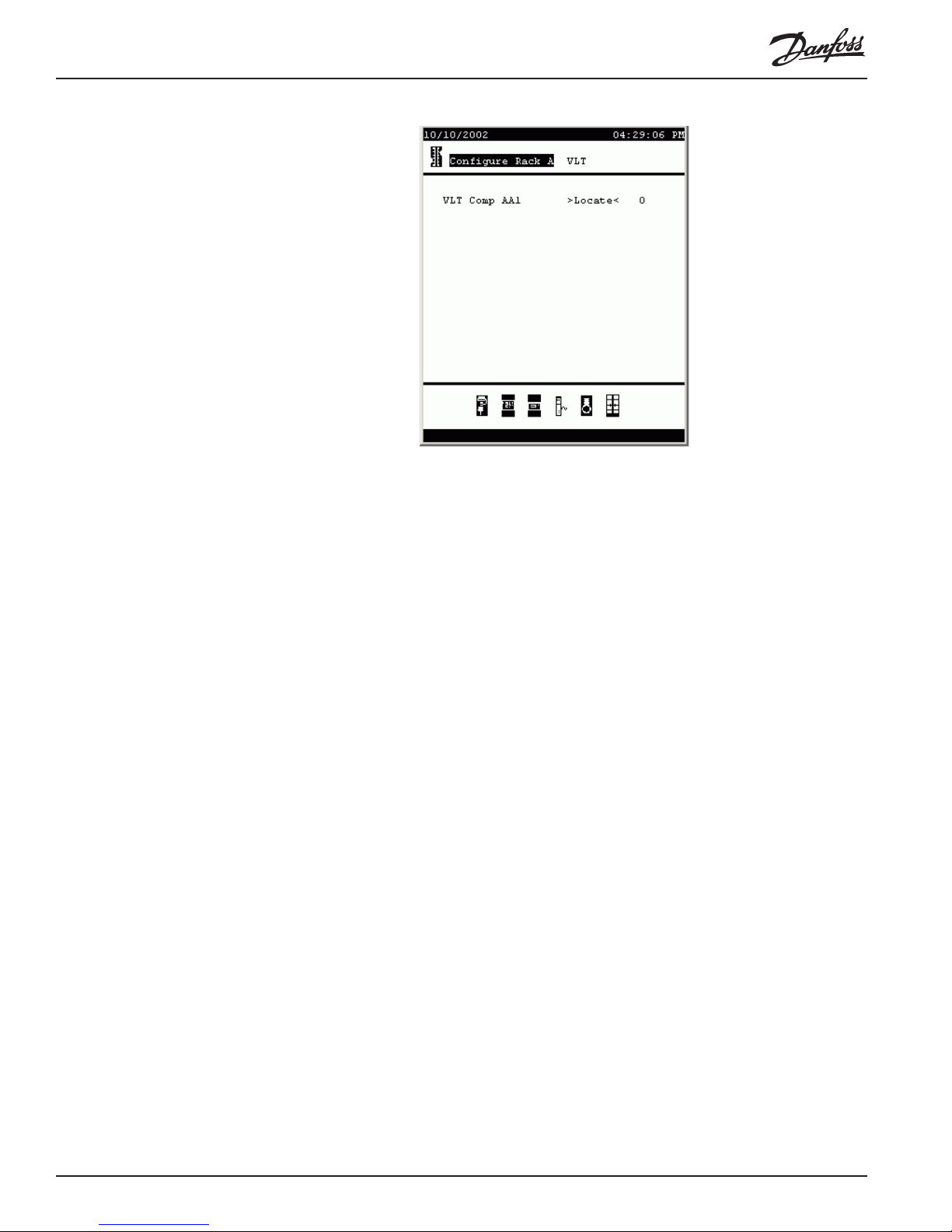
The fields and contents are:
Name (Label field: any 15 characters) The name of the
compressor being controlled by the VLT. The default
names for the system’s VLTs that were automatically
added during configuration of refrigeration are shown,
and will suffice in many applications. They can be
edited character by character (put the cursor on the
field, press +/- to change to edit mode; then use the left
and right arrow keys to move from space to space and
the up and down arrow keys to select the character for
that space. When the name appears as you want it,
press ENTER).
Locate (Button field) Each VLT must be located by the SC
255. Place the cursor on the Locate field and press
ENTER. Then, when instructed by a pop-up box on the
SC 255 screen, go to the VLT and press the service
pin. The SC 255 will then read the VLT address, which
will appear on the screen to the right of the Locate
field.
DCU circuits
Board & Points Section to be added.
62 AK2-SC 255 Reference Manual RS.8D.M1.22
Page 64

1- 3. Configuring HVAC
T o begin configuring HVAC, select Configuration from the Main Menu, then
HVAC. If there are no units configured, the screen looks as at left below. If one or
more units are already configured, a “menu” screen will appear that lists all the units,
as at right below. In the example, one unit of each possible type has been added. In
practice, this would be a very unlikely store.
To add a new unit, simply put the cursor on the No. of HVAC Units field and
increase the number by one. A new unit will appear with a default name, which will at
least temporarily be “Unit n”, where n is the new total number of units up to that line.
There are instructions below on how to change the name.
The fields in the HVAC Configuration Menu Evaporator Menu (shown above on the
right) are as follows:
No. of HVAC Units (0 to 45) The number of controlled HVAC units of all
types in the store.
No. of phase loss monitors: (0 to 45) The number of phase loss monitors available
for use by HVAC control. A phase loss monitor can be
used more than once.
No. of humidity sensors: (0 to 5, except that the combined number of humidity
and dewpoint sensors cannot exceed 5). The number
of humidity sensors used for control.
No. of dewpoint sensors: (0 to 5, except that the combined number of humidity
and dewpoint sensors cannot exceed 5). The number
of dewpoint sensors used for control.
Name (Label field, any 15 characters) The name of the
HVAC unit. The field can be edited character by
character (put the cursor on the field, press +/- to
change to edit mode; then use the left and right arrow
keys to move from space to space and the up and
down arrow keys to select the character for that
space. When the name appears as you want it, press
RS.8D.M1.22 AK2-SC 255 Reference Manual 6 3
Page 65

ENTER).
Type [for each individual listed HVAC unit] (List box:)
Note: a section explaining configuration of each of
the following types follows this section in the order
in which the types are given here.
RTU: The unit is a packaged rooftop unit.
AHU: The unit is a built-up system with an air han-
dling unit.
RTC: The unit is controlled by a Danfoss RTC board.
SC4: The unit is a Seasons 4 Smart Coil packaged
rooftop system.
CT-65: The unit is controlled by a Danfoss or ECI
ClimaTECH 65 controller.
CT-1024: The unit is controlled by a Danfoss or ECI
ClimaTECH 1024 controller.
Carrier: The HVAC unit is a Carrier Centurion or
Carrier Premier Link.
<Setup> (Button field) Used to enter the configuration screens
for the individual HVAC units. Y ou must ensuire that
you have selected the appropriate entry in the Type
column first.
RTU
Configuration When you press the <Setup> button for an RTU unit, the menu that appears looks
like this:
From this menu, you can enter the configuration screens for each of the components
of the HVAC unit.
RTU fan
configuration There are two pages for fan configuration:
64 AK2-SC 255 Reference Manual RS.8D.M1.22
Page 66

Fan type (List box:)
1-Speed: The unit has a single-speed fan.
2-Speed: The unit has a two-speed fan.
Fan control OPEN hours (List box:)
Continuous: The fan will run continuously during
open hours. Store open hours are defined in the Store
Info screens.
On demand: The fan will run on demand during open
hours. “On demand” means that the fan will run
whenever conditions calling for heating, heat reclaim,
cooling, dehumidification, or venting are met.
Fan control CLOSED hours(List box:)
Continuous: The fan will run continuously during
closed hours. Store closed hours are defined in the
Store Info screens.
On demand: The fan will run on demand during
closed hours. “On demand” means that the fan will run
whenever conditions calling for heating, heat reclaim,
cooling, dehumidification, or venting are met.
Post delay (0 to 60) The number of minutes that the fan will run
after the last stage of heating, cooling, etc. is turned
off.
RTU Fan
configuration , page 2 Monitor phase loss (List box: Yes, No) Whether or not a phase loss
monitor will be monitored.
Shutdown on phase loss (List box: Yes, No) Whether or not the unit is to be
shut down when its phase loss detector input is on.
Which phase loss (List box: ) All available phase loss monitors are
shown.
Shutdown on smoke detect (List box: Yes, No) Whether or not the unit is to be
shut down when its smoke detector is on.
Shutdown on fire alarm (List box: Yes, No) Whether or not the unit is to be
shut down when a monitored fire alarm is detected.
RS.8D.M1.22 AK2-SC 255 Reference Manual 6 5
Page 67

No of return sensors (0 to 5) The number return air temperature sensors.
Controlling sensor (List box:)
Min Temp: Display will be based on the lowest value
of all of the return air temperature sensors (if there are
more than one).
Max Temp: Display will be based on the highest
value of all of the return air temperature sensors (if
there are more than one).
Average: Display will be based on the average of all
the return air sensors (if there are more than one).
Return Air 1-1 (etc.): (each return air temperature
sensor will be available as a choice in the list) Display
will be based on the single selected sensor.
No of supply sensors (0 to 5) The number supply air temperature sensors.
Controlling sensor (List box:)
Min Temp: Display will be based on the lowest value
of all of the supply air temperature sensors.
Max Temp: Display will be based on the highest
value of all of the supply air temperature sensors.
Average: Display will be based on the average of all
the supply air sensors.
Supply Air 1-1 (etc.): (each supply air temperature
sensor will be available as a choice in the list) Display
will be based on the single selected sensor.
Lockout on proof failure (list box: yes, no)
Yes: The fan will be locked out if fan proof is lost for
five minutes. Human intervention will be needed to
restart the fan by using the “Clear” button on the status
screen. Evidence of the locked out condition, and the
means of ending the lockout, are found on the status
screen for cooling or heating function. Status screens
are covered in seciton II of this manual.
No: The fan will not be locked out on proof failure.
RTU cooling
configuration RTU cooling is configured after selecting cooling from the RTU configuration menu.
66 AK2-SC 255 Reference Manual RS.8D.M1.22
Page 68

Number of zone sensors (0 to 5) The number of zone sensors in the area of the
store served by this HVAC unit.
Controlling sensor (List box)
Min Temp: Control will be based on the lowest value
of all temperature sensors in the unit’s zone.
Max Temp: Control will be based on the highest
value of all of the temperature sensors in the unit’s
zone.
Average: Control will be based on the average of all
the temperature sensors in the unit’s zone.
Zone Temp 1-1 (etc.): (each zone temperature
sensor will be available as a choice in the list) Control
will be based on the single selected temperature
sensor.
Num of cooling stages (0 to 6) The number of cooling stages in this HVAC
unit.
Target temp. for stage (0.0 to 99.9) A separate field for each of the stages in
the unit.
Range +/- (0.0 to 9.9) The range selected creates a dead band.
For example, if the target is 72 and the range is 2, the
stage will come on at 74, and will not be turned off
until the temperature reaches 70.
Pre delay for stage (0 to 60) The number of minutes that must elapse
after target plus range is reached before the stage will
come on. There is one field for each stage.
Post delay for stage (0 to 60) The number of minutes that must elapse
after target - range is reached before the stage will be
turned off. There is one field for each stage.
RS.8D.M1.22 AK2-SC 255 Reference Manual 6 7
Page 69

RTU cooling
configuration, page 2 Refer to the screen above.
Ambient temp lockout: (List box: Yes, No) Whether or not there is to be a
No cooling below (0.0 to 100.0) The ambient temperature below which
Range +/- (0.0 to 9.9) The range selected creates a dead band.
Default fan Speed (List box: High Speed, Low Speed) The fan speed for
Max suction press safety (List box:) Lists every configured pressure sensor.
No cooling above (0.0 to 100.0) The pressure value of the sensor
Freeze protection (List box:)
Setpoint (0.0 to 50.0) The temperature, as measured by the
Night setback (List box: Yes, No) Whether or not the cooling
lockout based on low outside ambient temperature.
cooling will be locked out.
For example, if the lockout is 50 and the range is 2,
cooling will be locked out at 48 and will be allowed on
at 52.
cooling. A different fan speed can be chosen for
dehumidification when it is configured.
Any may be selected. Only the suction pressure for the
cooling compressors in this rooftop should be used.
selected on the previous line at and above which
cooling will be cut out. Cooling will not cut in again
until the pressure falls below this value and the pre
delay specified on the preceding page has elapsed.
Sensor Input: There is a leaving air temperature for
each stage of cooling, near the coil. At and below the
setpoint (next line), the cooling stage will be turned off.
On/Off Input: A single digital input that when ON will
turn off all stages of cooling in the R TU.
None: There is no freeze protection to configure.
sensor input indicated above, at and below which a
stage of cooling will be turned off.
setpoints are to be raised by an offset (next line) during
68 AK2-SC 255 Reference Manual RS.8D.M1.22
Page 70

scheduled times (next page) when cooling requirements are not as critical; for example, when the
building is closed.
Night setback offset (0.0 to 50.0) The amount by which the cooling setpoint
(set on previous page) is to be raised when night
setback schedules (next page) are in effect.
Override switch (List box: Yes, No) Whether or not there is a switch to
override night setback.
Override duration (0 to 1439) The number of minutes after, activation of
the override switch, that night setback will be overridden.
Num of schedules (0 to 8) The number of cooling night setback sched-
ules. Schedules are entered on the following page(s)
reached by using the PG DN key.
RTU Heating
configuration Heating configuration for rooftop units begins with selection of Heating from the
rooftop configuration menu.
Number of zone sensors (0 to 5) The number of zone sensors for the rooftop.
Controlling sensor (List box:)
RS.8D.M1.22 AK2-SC 255 Reference Manual 6 9
Changing this number will also change the number of
zone sensors in the first line of the first cooling configuration screen.
Min Temp: Control will be based on the lowest value
of all temperature sensors in the unit’s zone.
Max Temp: Control will be based on the highest
value of all of the temperature sensors in the unit’s
zone.
Average: Control will be based on the average of all
the temperature sensors in the unit’s zone.
Zone Temp 1-1 (etc.): (each zone temperature
sensor will be available as a choice in the list) Control
will be based on the single selected temperature
Page 71

RTU Heating auxiliary
heat configuration, p2:
staging strategy
sensor.
Num of heat rclm stages (0 to 2) The number of stages of heat reclaim in the
rooftop.
Target temp. stage 1 [There will be a target and delays for each stage
configured] (0.0 to 100.0) The target temperature for
the heat reclaim stage.
Pre delay: (0 to 60) The number of minutes after target minus
range is reached before the stage will be turned on.
Post delay: (0 to 60) The number of minutes after target plus
range is reached that the stage will be turned off.
Range +/- (0.0 to 9.9) The range applied to target prior for
control actions. See preceding two settings.
Auxiliary Heat type (List box:)
Staging: Auxiliary heat is staged.
None: There is no auxiliary heat.
Analog valve: Auxiliary heat is regulated by a modula
ting valve.
Fan speed (List box: High Speed, Low Speed) The fan speed for
heating.
Night setback (List box: Yes, No) Whether or not there is to be a
night setback for heat.
Night setback offset (0.0 to 50.0) The amount by which the heating setpoint
(set on previous page) is to be lowered during times
when night setback is scheduled.
Override switch (List box: Yes, No) Whether or not there is a night
setback override switch.
Override duration (0 to 1439) The number of minutes after operation of
the override switch that night setback will be overridden.
Num of schedules (0 to 8) The number of night setback schedules.
Schedules are entered on thelast page(s) reached by
using the PG DN key.
High supply temp lockout (List box: Yes, No) Whether or not heating is to be
locked out above a supply air temperature to be
specified on the following line.
Lockout above (0.0 to 999.9) Above this temperature plus deadband
(next field) heating will be shut down.
Deadband (0.0 to 50.0) The number of degrees above the lockout
setting where heating will be shut down. Also, the
number of degrees below the lockout setpoint where
heating will be allowed after being locked out.
70 AK2-SC 255 Reference Manual RS.8D.M1.22
Page 72

Num of aux heat stages (0 to 5) The number of auxiliary heating stages in this
HVAC unit.
Target temp. for stage (0.0 to 99.9) A separate field for each of the stages in
the unit.
Range +/- (0.0 to 9.9) The range selected creates a dead band.
Heat will cut in at target minus range, and cut out at
target plus range.
Pre delay for stage (0 to 60) The number of minutes that must elapse
after target plus range is reached before the stage will
come on. There is one field for each stage.
Post delay for stage (0 to 60) The number of minutes that must elapse
after target minus range is reached before the stage
will be turned off. There is one field for each stage.
Lockout aux ht. in setbk (List box: Yes, No) Whether or not auxiliary heat is to
be locked out during hours when setback is effective.
Ambient heat lockout (List box: Yes, No) Whether or not heat is to be
locked out based on ambient temperature.
No heat above (0.0 to 100.0) Auxiliary heat will be locked out above
this temperature plus range (next line). Heat will be
allowed on again when ambient temperature has fallen
to lockout minus range.
Range +/- (0.0 to 9.9) The range selected creates a dead band
around the lockout temperature. Heat will be locked
out at lockout temperature plus range, and once locked
out will be allowed on at ambient lockout minus range.
RTU Heating auxiliary
heat configuration, p2:
analog valve strategy With an analog gas valve selected, the second heating page looks instead like this:
RS.8D.M1.22 AK2-SC 255 Reference Manual 7 1
Page 73

Aux heat target temp (-50.0 to 100.0) The temperature you want to maintain
at the zone sensor.
Pre delay (0 to 60) The number of minutes that must elapse
after target plus range is reached before the analog
valve will open.
Post delay (0 to 60) The number of minutes that must elapse
after target minus range is reached before the analog
valve will be closed.
Lockout aux ht. in setbk (List box: Yes, No) Whether or not auxiliary heat is to
be locked out during hours when setback is effective.
Ambient heat lockout (List box: Yes, No) Whether or not heat is to be
locked out based on ambient temperature.
No heat above (0.0 to 100.0) Auxiliary heat will be locked out above
this temperature plus range (next line). Heat will be
allowed on again when ambient temperature has fallen
to lockout minus range.
Range +/- (0.0 to 999.9) The range selected creates a dead band
around the lockout temperature. Heat will be locked
out at lockout temperature plus range, and once locked
out will be allowed on at ambient lockout minus range.
Low Fire Position (0.0 to 100.0) The percentage of valve opening when
ignition occurs.
Low Fire Duration (1 to 20) The number of minutes the valve will be
maintained at low fire duration before beginning to
modulate.
Max valve opening (50.0 to 100.0) Sets the maximum valve opening
allowed.
Min valve opening (0.0 to 75.0) Sets the maximum valve opening al-
lowed.
Degrees to max opening (0 to 6) The number of degrees of rotation of the
valve spindle from minimum to maximum percentage.
72 AK2-SC 255 Reference Manual RS.8D.M1.22
Page 74

RTU dehumidification
configuration Begin by selecting Dehumidify from the Configure R TU menu.
Dehumidification type (List box: None, Cooling, Dessicant Whl) The type of
dehumidification used.
Rclm heat during dehumid (List box: Yes, No) Whether or not heat reclaim is
allowed during dehumidification.
Aux heat during dehumid (List box: Yes, No) Whether or not auxiliary heat is
allowed during dehumidification.
Control dehumid. on (List box:)
Humidity: Dehumidification will be controlled based
on a specified humidity target. A humidity sensor is
required.
Calc InDew: Dehumidification will be controlled
based on a specified dewpoint target, which will be
compared with a dewpoint calculated from inside zone
temperatuare and humidity. Both zone temperature
and humidity sensors must be installed.
Inside Dew: Dehumidification will be controlled
based on a specified inside dewpoint target. An inside
dewpoint sensor is required.
Calc OutDew: Dehumidification will be controlled
based on a specified dewpoint target, which will be
compared with a dewpoint calculated from outside
temperatuare and humidity. Outside temperature and
humidity sensors must be installed.
Outside Dew: Dehumidification will be controlled
based on a specified outside dewpoint target. An
outside dewpoint sensor is required.
Control sensor (List box, if controlled by dewpoint or humidity only,
and if there are multiple sensors:)
Min Humidity or Min dewpoint : Control will be
based on the lowest-reading of a group of sensors.
RS.8D.M1.22 AK2-SC 255 Reference Manual 7 3
Page 75

Max Humidity or Max dewpoint: Control will be
based on the highest-reading of a group of sensors.
Average: Control will be based on the average of a
group of sensors.
Dewpoint 1-1 (etc.) Any single dewpoint sensor can
be selected.
Humidity 1-1 (etc.) Any single humidity sensor can
be selected.
Control humidity sensor (List box similar to the preceding; appears only when
using Calc Dewpt as the control strategy.)
Control temp sensor (List box similar to the preceding; appears only when
using Calc Dewpt as the control strategy.)
Target (0.0 to 100.0) The control target in percent relative
humidity or dewpoint degrees depending on the strategy chosen above.
Target differential (0.1 to 15.0) The differential forms a deadband above
and below the target in which no control actions are
taken. Dehumidification will be turned on at target plus
differential and turned off at target minus differential.
Pre delay for stage (0 to 60) (Not present when dessicant wheel is
configured) The number of minutes that must elapse
after target plus range is reached before the stage will
come on. There is one field for each stage.
Post delay for stage (0 to 60) (Not present when dessicant wheel is
configured) The number of minutes that must elapse
after target minus range is reached before the stage
will be turned off. There is one field for each stage.
Cooling low limit (0.0 to 100.0) If zone temperature is below this limit,
dehumidification will be disallowed.
RTU dehumidification
configuration, page 2
Fan speed (List box: Low Speed, High Speed) The fan speed
74 AK2-SC 255 Reference Manual RS.8D.M1.22
Page 76

during dehumidification.
Monitor outside humidity (List box: Yes, No) Whether or not to monitor outside
humidity on status screens for this RTU.
Monitor wheel rotation (List box: Yes, No) (Present only when dessicant
wheel is configured) Whether or not the dehumidification target is to be raised by an offset (next line)
Night setback (List box: Yes, No) Whether or not the dehumidifica-
tion target is to be raised by an offset (next line)
according to a schedule or schedules on the next
page(s).
Night setback offset (0.0 to 100.0) The amount by which the dehumidifica-
tion setpoint (set on previous page) is to be raised
during night setback hours (as set on the following
schedule page).
Num of schedules (0 to 8) The number of night setback schedules
desired on the following schedule page(s).
R TU Air Damper
configuration For air damper configuration, select Air Damper from the Configure RTU menu.
Air Damper (List box: Yes, No) Whether or not there is a con-
Ambient temp lockout (List box: Yes, No) Whether or not the air damper is to
No air damper below (0.0 to 100.0) The air damper will be locked out below
Range +/- (0.0 to 9.9) The range selected creates a dead band
Num of schedules (0 to 8) The number of schedules that will be created
RS.8D.M1.22 AK2-SC 255 Reference Manual 7 5
trolled air damper.
be locked out based on ambient temperatuare.
this temperature minus range (next line). The air
damper will be allowed to open again again when
ambient temperature has risen to lockout plus range.
around the lockout temperature. The air damper will
be locked out at lockout temperature minus range, and
once locked out will be allowed to open at ambient
lockout plus range.
(below, and on following pages if needed) for air
Page 77

damper operation.
RTU Alarms
configuration Alarms can be for any of the following, in accordance with the Appendix on alarms.
High zone temp for each configured zone
Low zone temp for each configured zone
High humidity for each configured RH sensor
High supply temp for each configured supply air sensor
HVAC fan down for each fan speed
HVAC phase loss for this unit’s phase loss detector
HVAC smoke for this unit’s smoke detector
HVAC fire for this unit’s fire detector
RTU Board & Points
configuration See the Appendix on Board & Points
AHU
Configuration When you press the <Setup> button for an AHU unit, the menu that appears looks
like this:
Only the fan and outside air coil configuration for AHUs is dif ferent from configura-
tion for RTUs that was spresented in the previous section.
AHU fan
configuration There are two pages for AHU fan configuration:
76 AK2-SC 255 Reference Manual RS.8D.M1.22
Page 78

Fan type (List box:)
1-Speed: The unit has a single-speed fan.
2-Speed: The unit has a two-speed fan.
Variable VO: Fan speed is variable, with a drive
controlled by an analog output board (variable output
board).
V ariable VLT: A variable speed fan is controlled by a
Danfoss VLT adjustable frequency drive.
Fan control OPEN hours (List box:)
Continuous: The fan will run continuously during
open hours. Store open hours are defined in the Store
Info screens.
On demand: The fan will run on demand during open
hours, whenever heating, cooling, dehumidification, or
venting is called for.
Fan control CLOSED hours(List box:)
Continuous: The fan will run continuously during
hours when the store is not open. Store open hours are
defined in the Store Info screens.
On demand: The fan will run on demand during hours
when the store is not open., whenever heating, cooling,
dehumidification, or venting is called for.
Post delay (0 to 60) The number of minutes the fan will run after
the last stage of heating, cooling, dehumidification, or
venting is turned off.
Heat ramp up if LAT > (40.0 to 150.0) When heating is on, fan speed will be
ramped up when LAT (leaving air temperature) is
greater than this setpoint.
Cool ramp up if LAT < (40.0 to 70.0) When cooling is on, fan speed will be
ramped up when LAT (leaving air temperature) is less
than this setpoint.
Dehm ramp up if LAT < (30.0 to 60.0) When dehumidification is on, fan speed
will be ramped up when LAT (leaving air temperature)
RS.8D.M1.22 AK2-SC 255 Reference Manual 7 7
Page 79

is less than this setpoint.
Speed:
Inverter Min: (0.0 to 70.0) Max: (50.0 to 130.0) The highest
and lowest percent of rated maximum speed (last line
on the screen) that the inverter will be allowed to drive
the fan motor.
Heating Min: (10.0 to 100.0) Max: (50.0 to 130.0) The highest
and lowest percent of rated maximum speed (last line
on the screen) that the inverter will be allowed to drive
the fan motor when heating is on.
Cooling Min: (10.0 to 100.0) Max: (50.0 to 130.0) The highest
and lowest percent of rated maximum speed (last line
on the screen) that the inverter will be allowed to drive
the fan motor when cooling is on.
Dehumidification Min: (10.0 to 100.0) Max: (50.0 to 130.0) The highest
and lowest percent of rated maximum speed (last line
on the screen) that the inverter will be allowed to drive
the fan motor when dehumidification is on.
Heat Reclaim in Dehum.
Min: (10.0 to 100.0) Max: (50.0 to 130.0) The highest
and lowest percent of rated maximum speed (last line
on the screen) that the inverter will be allowed to drive
the fan motor when dehumidification is being used for
dehumidification
. Rpm at max speed (1 to 9999) The rated maximum speed of the fan
motor, from the data plate.
Second page
AHU Fan
Configuration Reaction Time (1 to 20) This setting together with the next regulate
the sensitivity of speed control. These should be left at
the default settings and should only changed by a
Danfoss-trained technician.
Algorithm Interval (1 to 15) This setting together with the preceding one
regulate the sensitivity of speed control. These should
be left at the default settings and should only changed
by a Danfoss-trained technician.
Inverter max resets (0 to 10) The number of reset attempts, when proof is
not detected, before the variable speed drive will be
placed in override.
Inverter reset delay (0 to 600) The number of seconds that must elapse
between resets.
Inverter proof delay (0 to 600) The number of seconds that must elapse
after proof is not detected, before a reset attempt.
Monitor phase loss (List box: Yes, No) Whether or not phase loss will be
monitored.
Shutdown on phase loss (List box: Yes, No) Whether or not the unit is to be
shut down when its phase loss detector input is on.
Shutdown on smoke detect (List box: Yes, No) Whether or not the unit is to be
shut down when its smoke detector is on.
Shutdown on fire alarm (List box: Yes, No) Whether or not the unit is to be
shut down when a monitored fire alarm occurs.
78 AK2-SC 255 Reference Manual RS.8D.M1.22
Page 80

No of return sensors (0 to 5) The number of return air temperature sensors.
Controlling sensor (List box:)
Min Temp: Control will be based on the lowest value
of all of the return air temperature sensors.
Max Temp: Control will be based on the highest
value of all of the return air temperature sensors.
Average: Control will be based on the average of all
the return air sensors.
Return Air 1-1 (etc.): (each return air temperature
sensor will be available as a choice in the list) Control
will be based on the single selected sensor.
No of supply sensors (0 to 5) The number of supply air temperature sen-
sors.
Controlling sensor (List box:)
Min Temp: Control will be based on the lowest value
of all of the supply air temperature sensors.
Max Temp: Control will be based on the highest
value of all of the supply air temperature sensors.
Average: Control will be based on the average of all
the supply air sensors.
Supply Air 1-1 (etc.): (each supply air temperature
sensor will be available as a choice in the list) Control
will be based on the single selected sensor.
AHU outside air coil
configuration When outside air coils are configured, the first cooling screen looks like this:
Number of zone sensors (0 to 5) The number of zone sensors in the area of the
Controlling sensor (List box)
RS.8D.M1.22 AK2-SC 255 Reference Manual 7 9
store served by this HVAC unit.
Min Temp: Control will be based on the lowest value
of all temperature sensors in the unit’s zone.
Max Temp: Control will be based on the highest
value of all of the temperature sensors in the unit’s
zone.
Page 81

Average: Control will be based on the average of all
the temperature sensors in the unit’s zone.
Zone Temp 1-1 (etc.): (each zone temperature
sensor will be available as a choice in the list) Control
will be based on the single selected temperature
sensor.
Num of cooling stages (0 to 6) The number of cooling stages in this HVAC
unit. Includes the number of outside air coils.
Num of outside air coils (0 to 2) The number of outside air coils in this HVAC
unit.
Consider dewpoint (List box: Yes, No) If Yes is chosen, the leaving air
temperature at the outside air coil needs to be less
than outside dewpoint for the coil to be active.
OA Coil LAT low limit (20.0 to 60.0) The leaving air temperature at and
above which outside air coils are enabled.
Enable OA Coil #1 above (40.0 to 95.0) (Question is repeated for OA coil #2, if
present) The leaving air temperature at and above
which the named outside air coil 1is enabled.
Target temp. for stage (0.0 to 100.0) (One target per cooling stage excluding
outside air coil stages) The target temperature that
you want the first stage to maintain at the zone sensor.
Range +/- (0.0 to 9.9) The range selected creates a dead band.
For example, if the target is 72 and the range is 2, the
stage will come on at 74, and will not be turned off
until the temperature reaches 70.
Pre delay for stage (0 to 60) (One setting per cooling stage.) The number
of minutes that must elapse after target plus range is
reached before the stage will come on.
Post delay for stage (0 to 60) (One setting per cooling stage.)The number
of minutes that must elapse after target - range is
reached before the stage will be turned off. There is
one field for each stage.
RTC
configuration The Danfoss RTC control board can function as a stand-alone or as a node on the I/O
network of an SC 255 system. To begin configuration, select RTC as the type of unit
in the Configure HVAC menu. A menu for the unit is then presented by the system.
Selecting Fan from the unit brings up the first fan configuration page, shown on the
left below; the second page is shown at the right.
80 AK2-SC 255 Reference Manual RS.8D.M1.22
Page 82

Fan type (List box:)
1-Speed: Single-speed fan.
Variable VO: Fan speed is variable, with a drive
controlled by the RTC board’s analog output (variable
output).
Fan control OPEN hours (List box:)
Continuous: The fan will run continuously during
open hours. Store open hours are defined in the Store
Info screens.
On demand: The fan will run on demand during open
hours, whenever heating, cooling, dehumidification, or
venting is called for.
Fan control CLOSED hours(List box:)
Continuous: The fan will run continuously during
hours when the store is not open. Store open hours are
defined in the Store Info screens.
On demand: The fan will run on demand during hours
when the store is not open., whenever heating, cooling,
dehumidification, or venting is called for.
Post delay (0 to 60) The number of minutes the fan will run after
the last stage of heating, cooling, dehumidification, or
venting is turned off.
Heat ramp up if LAT > (40.0 to 150.0) When heating is on, fan speed will be
ramped up when LAT (leaving air temperature) is
greater than this setpoint.
Cool ramp up if LAT < (40.0 to 70.0) When cooling is on, fan speed will be
ramped up when LAT (leaving air temperature) is less
than this setpoint.
Dehm ramp up if LAT < (30.0 to 60.0) When dehumidification is on, fan speed
will be ramped up when LAT (leaving air temperature)
is less than this setpoint.
Aux Heat ramp up if LAT >(0.0 to 100.0) When heating is on, fan speed will be
ramped up when LAT (leaving air temperature) is
RS.8D.M1.22 AK2-SC 255 Reference Manual 8 1
Page 83

greater than this setpoint
Speed:
Inverter Min: (0.0 to 70.0) Max: (50.0 to 130.0) The highest
and lowest percent of rated maximum speed that the
inverter will be allowed to drive the fan motor.
Heating Min: (10.0 to 100.0) Max: (50.0 to 130.0) The highest
and lowest percent of rated maximum speed that the
inverter will be allowed to drive the fan motor when
heating is on.
Cooling Min: (10.0 to 100.0) Max: (50.0 to 130.0) The highest
and lowest percent of rated maximum speed that the
inverter will be allowed to drive the fan motor when
cooling is on.
Dehumidification Min: (10.0 to 100.0) Max: (50.0 to 130.0) The highest
and lowest percent of rated maximum speed that the
inverter will be allowed to drive the fan motor when
dehumidification is on.
Speed control increment (0.0 to 20.0) The increment, in percent, by which
variable speed is increased when called for by an
increase in load.
Speed control decrement (0.0 to 20.0) The decrement, in percent, by which
variable speed is decreased when called for by an
decrease in load..
Variable Output range (List box:)
0-5 Volts: Sets the RTC board’s analog output for a
variable speed drive requiring 0-5 volts.
0-10 Volts: Sets the RTC board’s analog output for a
variable speed drive requiring 0-10 volts.
RTC fan, page 2 Reaction Time (1 to 20) This setting together with the next regulates
the sensitivity of speed control. These should be left at
the default settings and should only changed by a
Danfoss-trained technician.
Algorithm Interval (1 to 15) This setting together with the preceding one
regulate the sensitivity of speed control. These should
be left at the default settings and should only changed
by a Danfoss-trained technician.
Inverter max resets (0 to 10) The number of reset attempts, when proof is
not detected, before the variable speed drive will be
placed in override.
Inverter reset delay (0 to 600) The number of seconds that must elapse
between resets.
Inverter proof delay (0 to 600) The number of seconds that must elapse
after proof is not detected, before a reset attempt.
Monitor phase loss (List box: Yes, No) Whether or not phase loss will be
monitored.
Shutdown on phase loss (List box: Yes, No) Whether or not the unit is to be
shut down when its phase loss detector input is on.
82 AK2-SC 255 Reference Manual RS.8D.M1.22
Page 84

Shutdown on smoke detect (List box: Yes, No) Whether or not the unit is to be
shut down when its smoke detector is on.
Shutdown on fire alarm (List box: Yes, No) Whether or not the unit is to be
shut down when a monitored fire alarm occurs.
R TC Cooling
configuration Select Cooling from the configuration menu for an HVAC unit of type RTC:
Num of cooling stages (0 to 3) The number of cooling stages in this HVAC
unit.
Control cooling using (List box:)
Return Air: Cooling will be controlled to satisfy a
return air target temperature.
Average: Cooling will be controlled to satisfy an
average zone temperature target.
High: Cooling will be controlled to satisfy a zone
target temperature for the highest of a number of zone
temperature sensors.
Zone 1(etc.): (each supply zone temperature sensor
will be available as a choice in the list) Control will be
based on the single selected sensor.
Target differential (0.1 to 100.0) The differential selected creates a
control dead band around the target temperature. For
example, if the target is 72 and the range is 2, the
stage will come on at 74, and will not be turned off
until the temperature reaches 70.
Target temp. for stage: (0.0 to 99.9) A separate field for each of the stages in
the unit.
Pre delay for stage (0 to 15) The number of minutes that must elapse
after target plus range is reached before the stage will
come on. There is one field for each stage.
Post delay for stage (0 to 15) The number of minutes that must elapse
after target minus range is reached before the stage
will be turned off. There is one field for each stage.
RS.8D.M1.22 AK2-SC 255 Reference Manual 8 3
Page 85

Humidity adjusts target: (List box: Yes, No) Whether or not humidity will adjust
the cooling target temperature.
Humidity sensor (List box:)
Average: Cooling target modification will be based on
an average of two humidity sensors.
High: Cooling target modification will be based on the
highest of two humidity sensors.
Zone 1(etc.): (each zone humidty sensor will be
available as a choice in the list) Cooling target modification will be based on the single selected sensor.
Dynamic offset (-99.9 to 99.9) The number of degrees by which
humidity can adjust the target temperatures. W ithin the
range of humidity limiting the offset, a linear relationship will exist between humidity and offset. (see also
next two parameters).
No offset < (-99.9 to 99.9) The relative humidity below which
there will be no offset of target temperature.
Full > (-99.9 to 99.9) The relative humidity above which the
maximum offset of target temperature by humidity will
be applied.
Ambient temp lockout (List box: Yes, No) Whether or not cooling is to be
locked out below a set ambient temperature (next line).
No cooling below (0.0 to 100.0) The ambient temperature below which
cooling will be locked out.
Night setback (List box: Yes, No) Whether or not the cooling
setpoints are to be raised by an offset (next line) when
the store is closed according to a schedule or schedules
configured in the Store Info screens.
Night setback offset (-50.0 to 50.0) The amount by which the cooling
setpoint (set on previous page) is to be raised during
store closed hours (as set in the Store Info screen.
Minimum ON time (0 to 60) The minimum number of minutes cooling
must run after being turned on before being turned off.
Minimum OFF time (0 to 60) The minimum number of minutes cooling
must remain off after being turned off before being
turned on.
84 AK2-SC 255 Reference Manual RS.8D.M1.22
Page 86

RTC Heating
configuration
Num of heating stages (0 to 3) The number of stages of heat in the unit.
Control heating using (List box:)
Return Air: Heating will be controlled to satisfy a
return air target temperature.
Average: Heating will be controlled to satisfy an
average zone temperature target.
Low: Heating will be controlled to satisfy a zone
target temperature for the lowest of a number of zone
temperature sensors.
Zone 1(etc.): (each supply zone temperature sensor
will be available as a choice in the list) Control will be
based on the single selected sensor.
Target differential (0.1 to 100.0) The differential selected creates a
control dead band around the target temperature. For
example, if the target is 72 and the range is 2, the
stage will come on at 70, and will not be turned off
until the temperature reaches 72. The pre-delay and
post-delay must also be satisfied.
Target temp. for stage: (-50.0 to 99.9) A separate field for each of the stages
in the unit.
Pre delay for stage (0 to 15) The number of minutes that must elapse
after target plus range is reached before the stage will
come on. There is one field for each stage.
Post delay for stage (0 to 15) The number of minutes that must elapse
after target minus range is reached before the stage
will be turned off. There is one field for each stage.
Ambient temp lockout (List box: Yes, No) Whether or not heating is to be
locked out above a set ambient temperature (next line).
No heat above (0.0 to 100.0) The ambient temperature above which
heating will be locked out.
Night setback (List box: Yes, No) Whether or not the heating
setpoints are to be lowered by an offset (next line)
RS.8D.M1.22 AK2-SC 255 Reference Manual 8 5
Page 87

when the store is closed according to a schedule or
schedules configured in the Store Info screens.
Night setback offset (-50.0 to 50.0) The amount by which the heating
setpoint (set on previous page) is to be lowered during
non-scheduled hours (as set in the Store Info screens).
Minimum ON time (0 to 60) The minimum number of minutes heating
must run after being turned on before being turned off.
Minimum OFF time (0 to 60) The minimum number of minutes heating
must remain off after being turned off before being
turned on.control actions. See preceding two settings.
RTC dehumidification
configuration There are two pages of dehumidification configuration settings:
Dehumidification type (List box: None, Cooling) The type of dehumidification
Aux heat during dehumid (List box: Yes, No) Whether or not auxiliary heat is
Control dehumid. on (List box:)
Control dehumid. using (List box, if controlled by dewpoint or humidity only,
86 AK2-SC 255 Reference Manual RS.8D.M1.22
used.
allowed during dehumidification.
Humidity: Dehumidification will be controlled based
on a specified humidity target. A humidity sensor is
required.
Calc Dewpt: Dehumidification will be controlled
based on a specified dewpoint target, which will be
compared with a dewpoint calculated from zone
temperatuare and humidity . Both zone temperature
and humidity sensors must be installed.
and if there are multiple sensors:)
Average: Control will be based on the average of a
group of sensors.
High: The high value of a group of sensors will be
used.
Page 88

Zone 1 (etc.): Any single humidity sensor or combina-
tion of sensors will be used.
Target (0.0 to 100.0) The humidity or dewpoint value desired
at the controlling sensor or combination specified
above.
Target differential (0.1 to 15.0) The differential forms a deadband above
and below the target in which no control actions are
taken. Dehumidification will be turned on at target plus
differential and turned off at target minus differential.
Pre delay for stage (0 to 60) The number of minutes that must elapse
after target plus range is reached before the stage will
come on. There is one field for each stage.
Post delay for stage (0 to 60) The number of minutes that must elapse
after target minus range is reached before the stage
will be turned off. There is one field for each stage.
Cooling low limit (0.0 to 100.0) The temperature at and below which
dehumidification is disallowed.
Night setback (List box: Yes, No) Whether or not the dehumidifica-
tion target is to be raised by an offset (next line) during
store closed hours according to a schedule or sched-
ules in the Store Info screens.
Night setback offset (0.0 to 100.0) The amount by which the dehumidifica-
tion setpoint (set on previous page) is to be raised
during store closed hours according to a schedule or
schedules in the Store Info screens.
R TC Air Damper
configuration You will use one of two pages, depending on whether economizer control is used:
Air Damper (List box: Yes, No) Whether or not there is a con-
trolled air damper.
Control method (List box:)
Fan ON: The damper will be open whenever the fan
RS.8D.M1.22 AK2-SC 255 Reference Manual 8 7
Page 89

is on.
Economizer: Economizer control will be used, based
on either humidity or enthalpy .
Schedule: The air damper will be operated according
to a schedule or schedules (entered on the next page).
CO2 Ctrl: The air damper will be operated based on
the CO2 level in the HVAC unit’s zone.
Ambient temp lockout [appears when any control method except economizer
is used] (List box: Yes, No) Whether or not the air
damper is to be locked out based on ambient temperature.
No air damper below [appears when any control method except economizer
is used and question above is answered Yes](0.0 to
100.0) The air damper will be locked out below this
temperature.
Control economizer on (List box:) (appears only if economizer control is
selected)
Humidity: The air damper will be controlled based on
humidity .
Enthalpy: The air damper will be controlled based on
calculated enthalpy .
Humidity sensor to use (List box:)
Average: Enthalpy or humidity control will be based
on the average of two zone humidity sensors.
High: Enthalpy or humidity control will be based on
the highest of two humidity sensors.
Zone 1(etc.): (each zone humidty sensor will be
available as a choice in the list) Enthalpy or humidity
control will be based on the single selected humidity
sensor.
Lockout if outside above (0.0 to 100.0) The air damper will be locked out (shut)
if the outside temperature is above this setting.
Enthalpy differential (-99.9 to 99.9) In enthalpy control, when outside
enthalpy is less than inside enthalpy by this differential,
the damper will be allowed to open.
Use CO2 override (List box: Yes, No) Whether or not damper control is
to be overriden based on CO2 content of inside air.
Target CO2 amount (0 to 2000) When CO2 override is enabled, the CO2
level at which the damper is allowed open to bring in
fresh air.
Damper Controlled by (List box:)
Variable Out: The damper is modulated by the RTCs
analog output (variable output).
Relay Output: The damper is opened by a digital
output (relay output).
Min Damper Position (0.0 to 100.0) When a variable out is controlling, the
minimum percentage of damper opening allowed.
Max Damper Position (0.0 to 100.0) When a variable out is controlling, the
maximum percentage of damper opening allowed.
Variable Output range (List box:) When a variable out is controlling, the
88 AK2-SC 255 Reference Manual RS.8D.M1.22
Page 90

minimum percentage of damper opening allowed.
0-5 Volts: Sets the RTC board’s analog output for an
output over the range 0-5 volts.
0-10 Volts: Sets the RTC board’s analog output for
an output over the range 0-10 volts.
Reaction Time (1 to 99) This setting, together with the next, deter-
mines the sensitivity of variable output control. It
should be adjusted only by a Danfoss-trained techni-
cian.
Algorithm Interval (1 to 15) This setting, together with the previous one,
determines the sensitivity of variable output control. It
should be adjusted only by a Danfoss-trained techni-
cian.
RTC schedules The RTC schedules screen(s) allow entry of schedules for operation of the rooftop.
RTC alarm
configuration Alarms can be for any of the following, in accordance with the Appendix on alarms.
Sensor discard
Power failure
Filter (elapsed)
Filter (runtime)
HVAC smoke for this unit’s smoke detector
HVAC fire for this unit’s fire detector
Sensor alarms can be set for any of the zone or humidity sensors, for any relay output,
or for any digital input (on-off input).
RTC I/O Points
configuration These are configured in a manner unlike the Board & Points entries for other devices.
Select RTC I/O Points from the RTC configuration menu and the first screen, Relay
Outputs, appears.
Notice the set of icons across the bottom of the screen. These will allow you to reach
RS.8D.M1.22 AK2-SC 255 Reference Manual 8 9
Page 91

the other configuration screens and to initialize the RTC. From left to right, the icons
represent Relay Outputs (digital outputs), Sensor Inputs (analog inputs), On-off Inputs
(digital inputs), V ariable Outputs (analog outputs), and finally , R TC Controls (R TC
Address and Init).
Configuring RTC I/O
Relay Outputs Here are the fields for Relay Outputs:
Point (1 to 8) The number of the point.
Name (Label field, contents depend on system configuration)
The name of the point. The names are fixed, since the
hardware points on the RTC board are dedicated, and
can control only a single type of device as follows:
Point 1: Fan
Point 2: Economizer
Point 3: Cool 1
Point 4: Cool 2
Point 5: Cool 3
Point 6: Heat 1
Point 7: Heat 2
Point 8: Heat 3
On (List field:)
N-Open: The point is wired through normally open
contacts.
N-Open: The point is wired through normally open
contacts.
Configuring RTC I/O
Sensor Inputs Here is the screen for sensor inputs, reached with the second icon from left:
Point (1 to 8) The number of the point.
Name (Label field, contents depend on system configuration)
90 AK2-SC 255 Reference Manual RS.8D.M1.22
The name of the point. The names are fixed, since the
hardware points on the RTC board are dedicated, and
Page 92

can serve only for the listed devices. The names
always appear as in the illustration above, whether the
sensor is used or not.
Config (List field, one for each point:)
Yes: The sensor is configured. It should be installed if
this answer is given, or the configuration should be
changed.
No: The sensor is not configured. Its value can not be
used by the controller.
Rec: The sensor value is to be received from another
node (other than this RTC board) on the I/O network.
The board and point that is broadcasting the value must
be given in the next column.
AKC 55 Bd-Pt (Address field) If the sensor value is received from
another node on the I/O network, enter here the
address of the point that is to be received.
Configuring RTC I/O
on-off inputs Here is the screen for on-off (digital) inputs, reached with the third icon from left.
Note that the screen is divided in two parts: the upper half deals with inputs available
on the RTC board, and the lower half shows inputs that can be received from other
nodes on the I/O network. The names appear whether or not the points are configured or used.
First, the RTC Inputs:
Pt# (1 to 8) The number of the point.
Name (Label field, not changeable) The name of the point.
Config (List field, one for each point:)
RS.8D.M1.22 AK2-SC 255 Reference Manual 9 1
The names are fixed, since the hardware points on the
RTC board are dedicated, and can serve only for the
listed devices. The names always appear as in the
illustration above, whether the input is used or not.
Yes: The input is configured. It should be wired if this
answer is given, or the configuration should be
Page 93

changed.
No: The input is not configured. Its state can not be
used by the controller.
Rec: The input value is to be received from another
node (other than this RTC board) on the I/O network.
The board and point that is broadcasting the state of
the input must be given in the next column.
AK2-SC 2 55 Bd-Pt (Address field) If the input state is received from
another node on the I/O network, enter here the
address of the point that is to be received.
In the lower half of the screen, the SC 255 Inputs:
Name (Label field, not changeable) The name of the point.
The RTC board’s software can only use the listed
inputs from the I/O network. The names always
appear as in the illustration above, whether the input is
used or not.
Bcast (List field, one for each point:)
No: The input is not configured or its state is not to be
used by the controller.
Rec: The input value is to be received from another
node (other than this RTC board) on the I/O network.
The board and point that is broadcasting the state of
the input must be given in the next column.
On (List field:)
Voltage: The input state will read ON when the point
senses voltage.
No Voltage: The input state will read ON when the
point senses no voltage.
Bd-Pt (Address field) If the input state is received from
another node on the I/O network, enter here the
address of the point that is to be received.
Configuring RTC I/O
variable outputs Here is the screen for variable (analog) outputs, reached with the fourth icon from
left. The names appear if the points are configured.
92 AK2-SC 255 Reference Manual RS.8D.M1.22
Page 94

Pt# (1or 2) The number of the point.
Name (Label field, not changeable) The name of the point.
The names are fixed, since the hardware points on the
RTC board are dedicated, and can serve only for the
listed outputs. The names always appear as in the
illustration above, whether the input is used or not.
Range (List field, one for each point:)
0-10 V olt: The output will supply 0-10 Volts.
0-5 V olts: The output will supply The input is config-
ured. It should be wired if this
RTC Address
and Init Select the right-most icon on the Configure RTC I/O points screen, and you will see
this screen:
RS.8D.M1.22 AK2-SC 255 Reference Manual 9 3
Page 95

In the field labeled address, give the RTC an address from 0 to 99 that is unique
among all the RTC nodes on the I/O network for this SC 255. Remember that there
can be only 45 HVAC units per SC 255.
Any time an RTC node is changed or added, the network must be re-scanned and reinitialized.
After addressing and re-scanning, put the cursor on the Init field and press ENTER.
The initialization process will take a few seconds, with a success or failure confirmation message appearing briefly across the bottom of the screen. When successful,
configuration is complete.
Seasons 4 Smart Coil
HV AC Unit
configuration Smart Coil
unique configuration requirements. For these units, select SC4 as the type on the
Configure HVAC menu. At left below is the SC4 menu. At right is the screen for fan
configuration.
®
packaged HVAC systems (manufactured by Seasons 4, Inc.) have some
Motor delay time (5 to 255) The fan motor runs continuously at low
Monitor phase loss (List box: Yes, No) Whether or not a phase loss
Which phase loss monitor (List box) Select from any of the configured phase
Shutdown phase loss (List box: Yes, No) Whether or not the fan is to be
Shutdown on smoke detect (List box: Yes, No) Whether or not the unit is to be
Shutdown on fire alarm (List box: Yes, No) Whether or not the unit is to be
94 AK2-SC 255 Reference Manual RS.8D.M1.22
speed. When there is a call for cooling, heating, or
dehumidification, the fan switches to high speed after
the motor delay set here elapses.
detector is to be monitored.
loss monitors.
shut down on detection of a phase loss.
shut down when its smoke detector is on.
shut down when a fire alarm monitor detects a fire
Page 96

SC4 cooling
configuration
alarm.
No of zone sensors (0 to 5) The number of zone temperature sensors.
Controlling sensor (List box:)
Min Temp: Control will be based on the lowest value
of all of the zone temperature sensors.
Max Temp: Control will be based on the highest
value of all of the zone temperature sensors.
Average: Control will be based on the average of all
the zone temperature sensors.
Zone Temp 4-1 (etc.): (each zone temperature
sensor will be available as a choice in the list) Control
will be based on the single selected sensor.
Num of cooling stages (List box: None, Four) Of the four cooling stages in
the unit, the number to be controlled by the AKC 55.
Either all units are controlled or none are controlled.
Setpoint (0.0 to 100.0) The desired temperature at the control-
ling sensor.
Range +/- (-9.9 to 9.9) The range selected creates a dead band.
For example, if the target is 72 and the range is 2, the
stage will come on at 74, and will not be turned off
RS.8D.M1.22 AK2-SC 255 Reference Manual 9 5
Page 97

SC4 heating
configuration
until the temperature reaches 70.
Ambient temp lockout: (List box: Yes, No) Whether or not there is to be a
lockout based on low ambient temperature.
No cooling below (0.0 to 100.0) The ambient temperature below which
cooling will be locked out.
Range +/- (0.0 to 9.9) The range for the lockout. Cooling will be
locked out at lockout minus range, and when locked out
will be allowed on at lockout plus range.
Minimum run time (0 to 20) The number of minutes that a stage must run
before being turned off.
Delay between stages (0 to 20) The number of minutes that must elapse
after a stage is turned on before the next stage can be
turned on.
No of zone sensors (0 to 5) The number of zone temperature sensors.
Controlling sensor (List box:)
Num of ht rclm stages (0 to 4) The number of heat reclaim stages in the SC4
Setpoint (0.0 to 100.0) The desired temperature at the control-
Range +/- (0.0 to 9.9) The range selected creates a dead band.
96 AK2-SC 255 Reference Manual RS.8D.M1.22
Min Temp: Control will be based on the lowest value
of all of the zone temperature sensors.
Max Temp: Control will be based on the highest
value of all of the zone temperature sensors.
Average: Control will be based on the average of all
the zone temperature sensors.
Zone Temp 4-1 (etc.): (each zone temperature
sensor will be available as a choice in the list) Control
will be based on the single selected sensor.
unit.
ling sensor when heat reclaim is being used.
Page 98

For example, if the target is 68 and the range is 2, the
stage will come on at 66, and will not be turned off
until the temperature reaches 70.
Num of aux heat stages (0 to 4) The number of auxiliary heat stages in the
SC4 unit.
Setpoint (0.0 to 100.0) The desired temperature at the control-
ling sensor when auxiliary heat is being used.
Range +/- (0.0 to 9.9) The range selected creates a dead band.
For example, if the target is 68 and the range is 2, the
stage will come on at 66, and will not be turned off
until the temperature reaches 70.
Ambient temp lockout: (List box: Yes, No) Whether or not there is to be a
lockout based on low ambient temperature.
No heat above (0.0 to 100.0) The ambient temperature above which
heating will be locked out.
Range +/- (0.0 to 9.9) The range for the lockout. Heating will be
locked out at lockout plus range, and when locked out
will be allowed on at lockout minus range.
Minimum run time (0 to 20) The number of minutes that a stage must run
before being turned off.
Delay between stages (0 to 20) The number of minutes that must elapse
after a stage is turned on before the next stage can be
turned on.
Night setback (List box: Yes, No) Whether or not the heating
setpoints are to be raised by an offset (next line)
during the times when cooling is not scheduled to be
on according to a schedule or schedules (next page).
Night setback offset (0.0 to 50.0) The amount by which the heating
setpoints are to be raised during night setback.
Override switch (List box: Yes, No) Whether or not there is an over-
ride switch wired to a digital input.
Override duration (0 to 1439) The number of minutes that control will be
overridden after operation of the override switch.
Num of schedules (0 to 8) The number of operating schedules entered on
the following page(s).
RS.8D.M1.22 AK2-SC 255 Reference Manual 9 7
Page 99

SC4 dehumidification
configuration
Num of stages (List box: None, Four) Whether or not dehumidifica-
tion is controlled in the SC4 unit. All SC4 units have
four stages of dehumidification.
Setpoint (0 to 99) The percent desired relative humidity in the
zone.
Range +/- (1 to 15) The range selected creates a dead band. For
example, if the target is 45% and the range is 2,
dehumidification will come on at 47, and will not be
turned off until humidity reaches 43%.
Cooling low limit (0.0 to 100.0) The zone temperature below which
mechanical cooling configured for dehumidification will
be disallowed.
Ambient temp lockout: (List box: Yes, No) Whether or not there is to be a
lockout based on low ambient temperature.
No dehum below (0.0 to 100.0) The ambient temperature below which
dehumidification will be locked out.
Range +/- (0.0 to 9.9) The range for the lockout. Dehumidifica-
tion will be locked out at lockout minus range, and
when locked out will be allowed on at lockout plus
range.
Minimum run time (0 to 20) The number of minutes that a stage must run
before being turned off.
Delay between stages (0 to 20) The number of minutes that must elapse
after a stage is turned on before the next stage can be
turned on.
Night setback (List box: Yes, No) Whether or not the dehumidifica-
tion setpoint is to be raised by an offset (next line)
when dehumidification is not scheduled to be on
according to a schedule or schedules (next page).
Night setback offset (0 to 99) The number of % by which the dehumidifica-
tion setpoint is to be raised during night setback.
98 AK2-SC 255 Reference Manual RS.8D.M1.22
Page 100

SC4condenser
configuration
Override switch (List box: Yes, No) Whether or not there is an over-
ride switch wired to a digital input.
Override duration (0 to 1439) The number of minutes that control will be
overridden after operation of the override switch.
Num of schedules (0 to 8) The number of operating schedules entered
on the following page(s).
Seasons 4 password (5-character auth code) The password given by
Seasons 4 to the equipment owner.
Number of fans (List box: None, Six, Eight) The number of HVAC
condenser fans controlled in this unit.
Minimum run time (0 to 60) The number of minutes that a stage must run
before being turned off.
Liquid Temp Setpoint (0.0 to 150.0, one setpoint per stage) The stage will be
turned on at setpoint plus range and turned off after
the stage above is turned off, at setpoint minus range.
Range (0.0 to 150.0, one setpoint per stage) The stage will be
turned on at setpoint plus range and turned off after the
stage above is turned off, at setpoint minus range.
SC4 alarms
configuration SC4 alarms are configured as are RTU alarms.
SC4 board & points
configuration SC4 board & points are configured as are RTU board & points.
RS.8D.M1.22 AK2-SC 255 Reference Manual 9 9
 Loading...