


MAKING MODERN LIVING POSSIBLE
Installation Guide
Danfoss Air Units
www.heating.danfoss.com

Danfoss A/S is not liable or bound by warranty if these
instructions are not adhered to during installation or service.
The English language is used for the original instructions.
Other languages are a translation of the original instructions.
(Directive 2006/42/EC)
© 2014 Copyright Danfoss A/S

Installation Guide
GB .
Installationsvejledning
Installationshandbuch
Instrukcja montażu
DK .
DE .
PL .

Installation Guide Danfoss Air Units
Table of Contents
1 Safety Note .................................................................... 2
2 Before Start .................................................................... 2
3 Installation of Air Units ............................................................ 3
4 Installation of CCM Module and Air Dial ................................................. 4
4.1 Electrical connections .......................................................... 4
4.2 Wireless connection ........................................................... 4
4.3 Air Dial .................................................................... 4
4.4 Mounting and removing CCM module and Air Dial ........................................ 5
5 Connecting to Danfoss Link™ CC ...................................................... 5
5.1 Connecting the Air Unit to Danfoss Link™ CC, physical installation .............................. 5
5.2 Connecting the Air Unit to Danfoss Link™ CC, wireless inclusion ............................... 6
5.3 Performing a network test after adding a new device ...................................... 6
5.4 Setting basic steps in the Danfoss Link™ CC ............................................ 7
6 Balancing of the Main Air Volume ..................................................... 7
7 Service Menu ................................................................... 8
8 Technical Specifications ............................................................ 9
8.1 a² Unit .................................................................... 9
8.2 a³ Unit .................................................................... 11
8.3 w¹ Unit .................................................................... 13
8.4 w² Unit .................................................................... 15
9 Troubleshooting ................................................................. 16
1 Safety Note
This appliance is not intended for use by persons (including children) with reduced physical, sensory or mental capabilities, or lack of
experience and knowledge, unless they have been given supervision or instruction concerning use of the appliance by a person responsible for their safety.
Children should be supervised to ensure that they do not play with the appliance.
Apart from the replacement of air filters and exterior cleaning of the system, any kind of maintenance will require the use of trained
personnel.
2 Before Start
Check the Danfoss Air Unit packing list to ensure that the shipment is complete.
If a complete Danfoss Air Solution is ordered, a packing list for the Air Flex duct system is included.
Inspect to ensure that no parts or components have been damaged.
Standard delivery includes:
Danfoss Air Unit
▪
Wall bracket (if w-model)
▪
CCM
▪
Cabels
▪
Optional deliveries:
Air Dial
▪
▪
Danfoss LinkTM CC
2
VIEWB302 Danfoss Heating Solutions
2
4
1
2
3
4
5
6
1
1 cm
2
3
5
75 mm
1
2
3
4
5
6
Installation Guide Danfoss Air Units
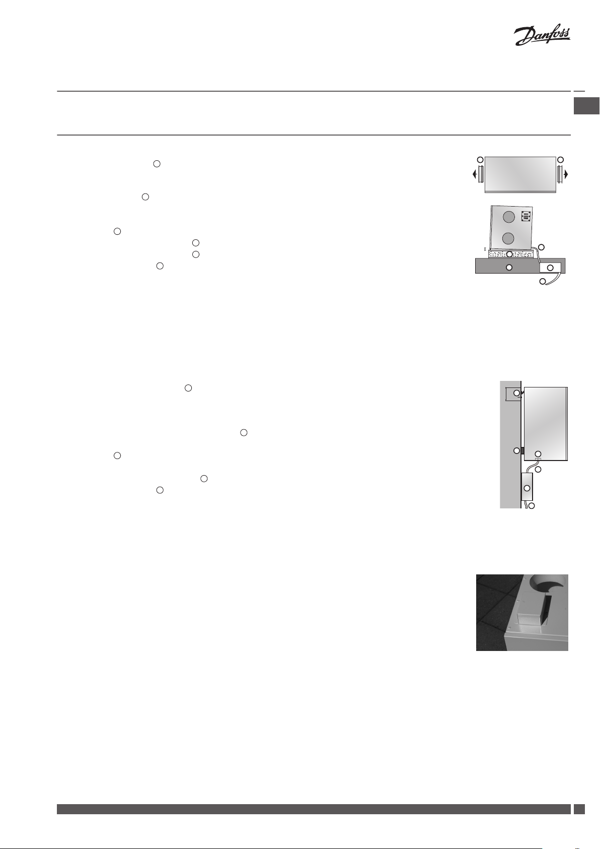
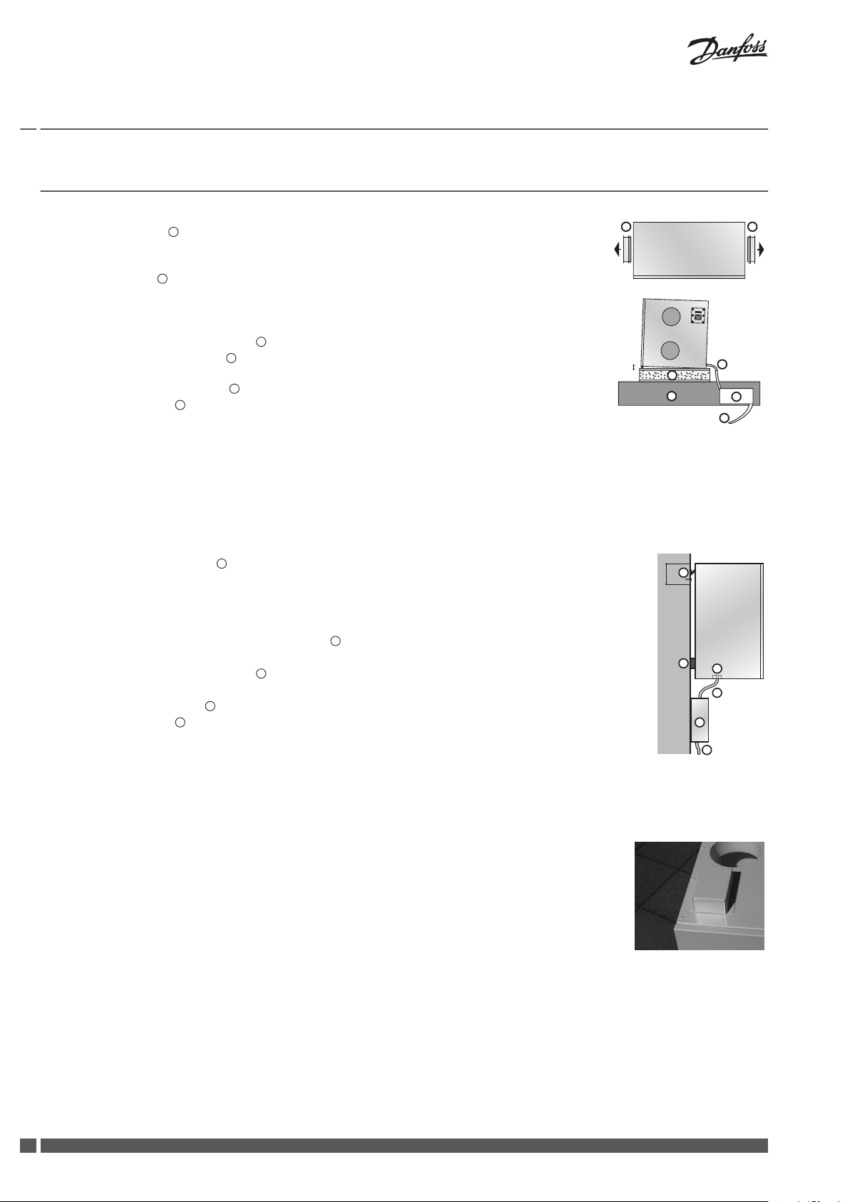
3 Installation of Air Units
Attic Units a² and a³
1. Pull out the spigots 1. Never lift the unit into the spigots, as it can damage the unit.*
2. Turn the spigots around and mount them using the included tapping screws (for power drill,
use lowest torque setting).
3. Make a platform
4. Allow for 60 cm free space in front of unit, to assure service access.
5. Make sure the unit is mounted with a minor backward fall.
6. A siphon 5 must always be installed with the unit (to be ordered separately).
7. Mount the siphon on the joist
8. Connect the siphon to a drain 6.
9. The condensate line 3 must be insulated where risk of freezing occurs.
10. Connect the hose to the unit outlet condensate spigot. Lead the connected pipe to the outlet, allowing for a gradient of min. 1 cm/metre.
11. Remove the front panel and foam front, fill the condensate tray, check the outlet and reassemble the front.
* If the unit is lifted into the spigots, it might cause leakage between the steel cabinet and the polystyrene core. The leakage can be fixed from the inside of the unit by sealing the spigots with an acrylicbased sealant.
for the unit of 16 mm plywood or MDF sheet around 50 mm wall batts.
below the unit or in the room below the attic.
GB .
Wall Units w¹ and w²
1. Place the mounting bracket 1 on the wall in desired position (75 mm from bracket bottom to
unit top), mark up and drill holes. Use screws suitable for the wall surface (not included).
2. Make sure that the bracket is mounted absolutely horizontal.
3. Hang the unit onto the bracket.
4. Attach the self-adhesive rubber separators
to the lower rear back plate.
5. Allow for 60 cm free space in front of unit, to assure service access.
6. A siphon
must always be installed with the unit (to be ordered separately).
7. Mount the siphon on the wall below the unit.
8. Connect the siphon to the drain
at the unit bottom.
9. The condensate line 4 must be insulated where risk of freezing occurs.
10. Connect the hose to the unit outlet condensate spigot. Lead the connected pipe to the outlet, allowing for a gradient of min. 1 cm/metre.
11. Remove the front panel and foam front, fill the condensate tray, check the outlet and reassemble the front.
Wall Unit w¹
In order to comply with safety standards and avoid the risk of malfunction, the supplied protection shield must be mounted on top of the w¹-unit covering the connector plate.
Danfoss Heating Solutions VIEWB302
3
1
2
3
4
5
6
1
2
3
4
!
Installation Guide Danfoss Air Units
4 Installation of CCM Module and Air Dial
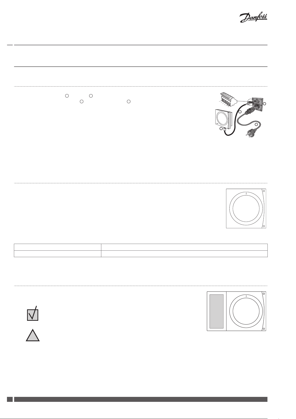
4.1 Electrical connections
1. Connect power cable 4 to Air unit 3.
2. Plug in communication cable 2 between CCM module 1 and Air unit.
3. Check the signal. If it is too weak, the CCM module should be placed elsewhere, e.g. on the
same floor as as the Air Dial (see Air Dial Link Test).
4. If possible, place the CCM module close to an ethernet connection for future connection to
PC.
5. If accessories (electrical preheating, electrical afterheating, water heating surface or geothermal surface) are present, the pin on terminals 5 and 6 must be removed (also see the
instructions included with the accessories).
Communication cable connections:
1. White/Orange, 2. Orange, 3. Black, 4. White/Blue, 5. Blue, 6. Black
Note! The communication cable can be extended up to 200 m. Use shielded cable , 22 or 24 AWG with 2 x twisted pair.
4.2 Wireless connection
When powering up the CCM module a green LED will flash slowly, indicating the CCM module
has yet to be connected to the Air Dial.
To connect the Air Dial, insert the batteries. The Air Dial starts in installation mode and automatically guides through the set-up.
1. Set language.
2. Create network (press button on CCM module and then press Air Dial).
3. Set basic step (setting up the main air volume).
4. Finish.
Green LED lights continuously Connected established
Red LED flashes slowly 5 times Connection attempt failed, see Troubleshooting.
Tab. 2: LED blink patterns on the CCM
4.3
Air Dial
The Air Dial has an integrated temperature sensor. To ensure best possible performance,
place the Air Dial according to following guidelines:
Place the Air Dial 80-150 cm above floor level.
▪
Place the Air Dial free of curtains etc.
▪
Place the Air Dial where the temperature is representative.
▪
Do not place the Air Dial in bathrooms.
▪
Do not place the Air Dial in direct sunlight.
▪
Do not place the Air Dial onto outer wall.
▪
Do not place the Air Dial directly above heat source.
▪
4
VIEWB302 Danfoss Heating Solutions
2
1
2
1
1
1
2
1
2
1
2
3
4
5
6
1
2
3
4
Installation Guide Danfoss Air Units
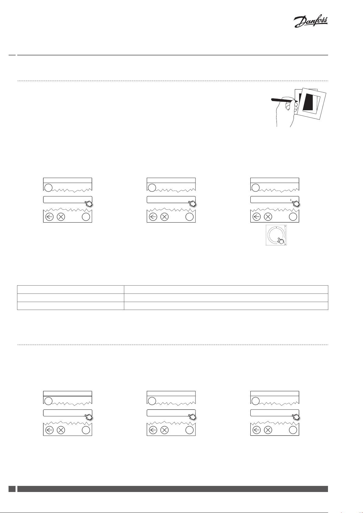
Air Dial Link Test
Before mounting the Air Dial permanently, perform a link test to ensure that transmission conditions are sufficient for the required location:
1. Press the Air Dial button for 5 seconds to access the Service Menu (The Service Menu remains visible for one hour).
2. Select the Link Test function.
3. The function shows if the transmission conditions are sufficient or not.
4. If the link test fails, see Troubleshooting.
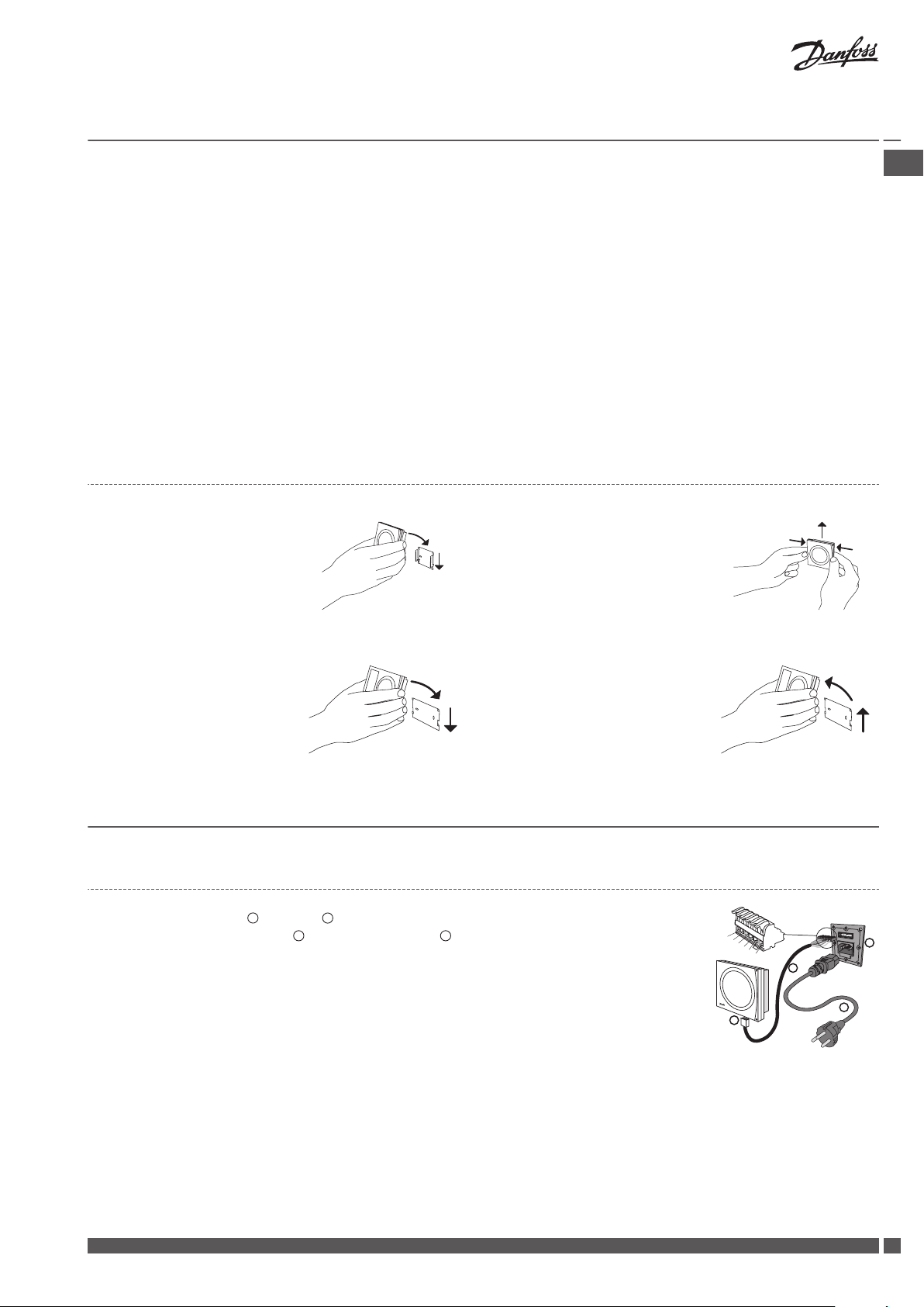
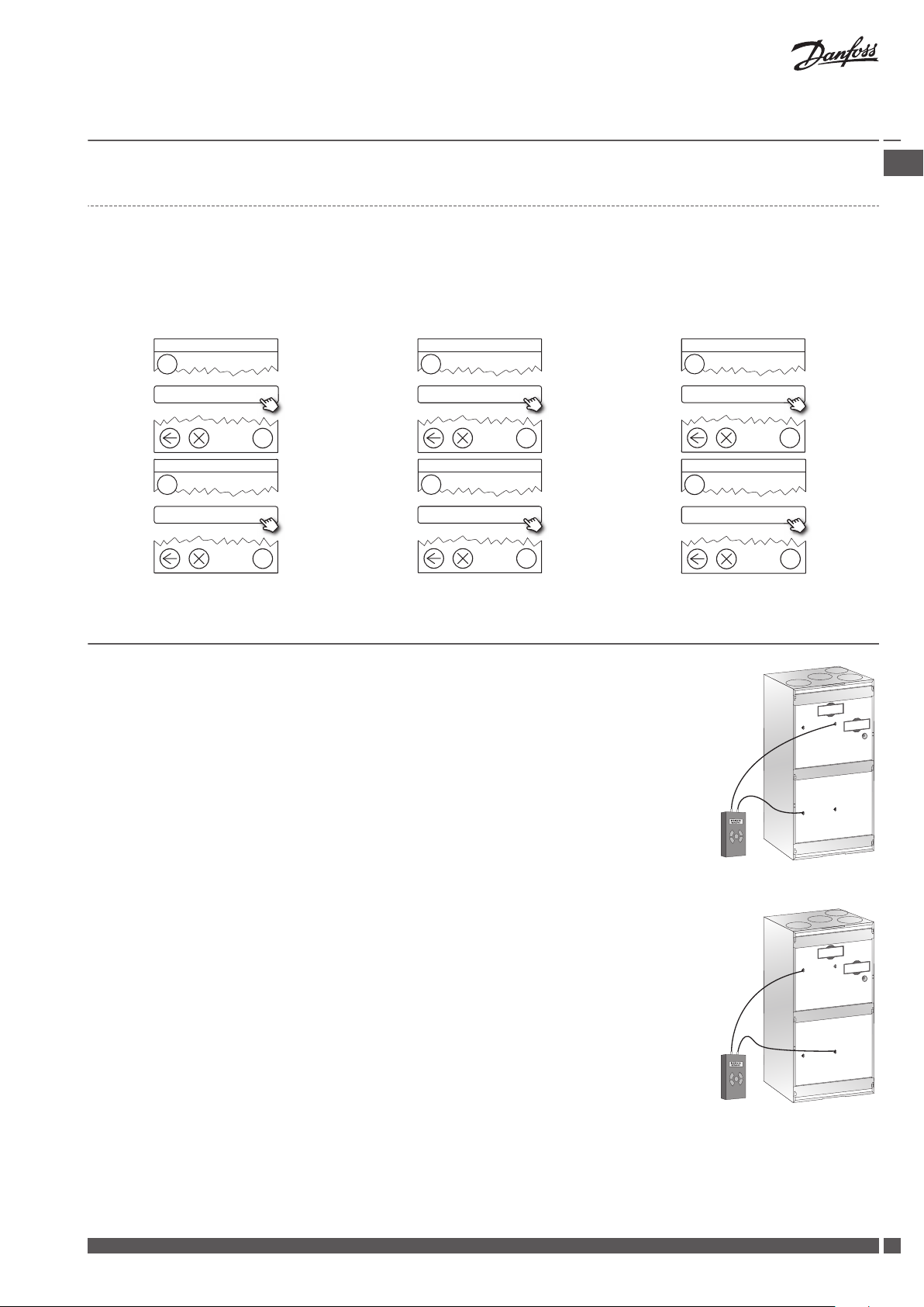
4.4 Mounting and removing CCM module and Air Dial
CCM module
Mounting:
1. Place the CCM on the wall
bracket.
2. Press downwards to click the
CCM into place.
Removing:
1. Press in the two latches on the
side.
2. Pull the CCM upwards.
GB .
Air Dial
Mounting:
1. Place the Air Dial on the wall
bracket.
Removing:
1. Lift the Air Dial.
2. Pull the Air Dial away.
2. Press downwards to click the
Air Dial into place.
5 Connecting to Danfoss Link™ CC
5.1 Connecting the Air Unit to Danfoss Link™ CC, physical installation
1. Connect power cable 4 to Air unit 3.
2. Plug in communication cable 2 between CCM module 1 and Air unit.
3. If possible, place the CCM module close to an ethernet connection for future connection to
PC.
4. If accessories (electrical preheating, electrical afterheating, water heating surface or geothermal surface) are present, the pin on terminals 5 and 6 must be removed (also see the
instructions included with the accessories).
5. The Air Unit is now ready to be added to the Danfoss Link™ CC.
Communication cable connections:
1. White/Orange, 2. Orange, 3. Black, 4. White/Blue, 5. Blue, 6. Black
Note! The communication cable can be extended up to 200 m. Use shielded cable , 22 or 24 AWG with 2 x twisted pair.
Danfoss Heating Solutions VIEWB302
5
?
1
Service Options
Rooms and Devices
?
2
Rooms and Devices
Add Service Devices
?
3
Add Service Device
Begin Registration
?
1
Service Options
Status and Diagnostics
?
2
Status and Diagnostics
Network
?
3
Wireless Network Status
Start Network Test
Installation Guide
Danfoss Air Units
5.2 Connecting the Air Unit to Danfoss Link™ CC, wireless inclusion
Remove the front cover of the Danfoss Link™ CC by gently pulling it off, pull near the
▪
edges of the cover.
Press the SETUP pin for 3 seconds to enter the service area.
▪
Note!
The Air Unit must be added to the network as a service device. For further instructions on the network inclusion, see the installation guide
▪
supplied with the Danfoss Link™ CC.
Add any dedicated repeater units (CF-RU) BEFORE adding the Air Unit to the wireless network.
▪
Click here on the CCM for adding the Air
Unit
Note! During installation, the distance between the Danfoss Link™ CC and the CCM must not exceed 1.5m.
Green LED flashes slowly
CCM module has not yet been connected to the Danfoss Link™ CC
Green LED lights continuously CCM module is now connected to the Danfoss Link™ CC
Red LED flashes slowly 5 times Connection attempt failed
Tab. 2: LED blink patterns on the CCM
5.3
Performing a network test after adding a new device
After finishing installation, perform a network test, to ensure that communication between added devices and the Danfoss Link™ CC is
stable.
Note! Do not perform the network test before the Danfoss Link™ CC is mounted in its final position.
At the end of the network test the Danfoss Link™ CC awaits for all battery operated devices to wake up and report. Follow the instructions given on the screen. If the network test is running smoothly, there will be no need for further interaction. If the network test is
performing slow, the Danfoss Link™ CC guides through troubleshooting and gives usefull tips for speeding up the process.
6
VIEWB302 Danfoss Heating Solutions
?
1
Service Options
Rooms and Devices
?
2
Rooms and Devices
Manage Devices
?
3
Manage Devices
Congure device
?
4
Select Device
Air unit
?
5
Congure Device
System settings
?
6
System settings
Set basic steps
Installation Guide Danfoss Air Units
5.4 Setting basic steps in the Danfoss Link™ CC
Now the Air Unit has been added to the wireless system, and is ready for balancing of the air flow. If the Air Unit has just been added to
the system, the screen will prompt for setting the basic extract and supply air step.
If the system was started earlier/by others, enter the basic settings through the Service Menu by pressing the Air Dial button for 5 seconds. Go through the following steps.
GB .
6 Balancing of the Main Air Volume
To achieve the best possible performance, it is vital to balance the main air volumes (balancing
will also help protecting the house against fungus and dry rot). The system should not be balanced/commisioned at outdoor temperatures below -3°C, as the system will go into frost protection mode (indicated by a flashing icon on the display. If necessary to perform balancing at
outdoor air temperatures below -3°C, remove power for 20 seconds to de-activate frost protection for 90 minutes.
Note! Close all doors and turn off the cooker hood.
1. Remove the front panel from unit by pulling the handles.
2. See the drawing of the duct system, where suggested pre-setting values for all air valves
are stated. Close the valves completely, and turn them full turns towards open (number of
turns as indicated on the duct system drawing). When setting up the systems for which
Danfoss has not dimensioned the duct system, set the supply and extract valves in accordance with the instructions of the project manager.
3. If dampers are included in the system, open these completely.
4. Mount measuring tubes between the unit’s measuring points on the extract side and differential pressure gauge.
5. Find the required flow on the system diagram (sticker on front cover) with the corresponding differential pressure value. If the pressure is too low, adjust the fan step upwards until
you reach the required pressure.
6. Move the measuring tubes to the measuring points on the supply side and use the same
procedure to set the supply air.
7. After the main air volumes have been adjusted, the set-up of individual valves needs to be
carried out. In most cases, this will entail minor changes to the chosen basic steps, but this
can be done in the room by adjusting the valves, or by using the Air Dial to fine tune basic
steps.
Measuring the extract
Adjusting an operational system
1. Press Air Dial for 5 seconds to get access to the Service menu.
2. Press ”set basic step” to activate the special commissioning mode (where all outside influences are blocked - the installer controls the extract and supply air fans completely with
1-100% fan speed). The Service menu remains visible for one hour and then disappears.
Danfoss Heating Solutions VIEWB302
Measuring the supply
7

Service
Back
Info
Set filter timer
Set language
Set basic step
Link test
Accessories
Installation Guide Danfoss Air Units
7 Service Menu
Press Air Dial for 5 seconds to access the Service Menu to change basic settings like language,
filter timer, basic steps etc.
System Reset
1. If the system has already been balanced, make a note of the basic fan steps for later use.
The values are found in the Service Menu: Service > Info > Basic Steps.
2. Remove and re-insert the Air Dial batteries while pressing the button until a beep is heard.
The Air Dial is now in start-up mode.
3. Remove the supply or communication cable.
4. While re-connecting the cable, press the CCM module button until only the green LED is
flashing.
5. The system is now reset to factory settings.
8
VIEWB302 Danfoss Heating Solutions
450
325
177
160
1263
1180
600
1
2
3
4
580
450
325
177
1
2
3
4
1
2
3
4
5
6
6
5
1
2
3
4
5
6
100%
85%
1000 J/m³
70%
58%
46%
33%
21%
350
300
250
200
150
100
50
0
0 50 100 150 200 250 300 350 400 450
*0.45 W/m³/h
83%
84%
85%
86%
87%
88%
89%
90%
91%
92%
93%
94%
0 50 100 150 200 250 300
Installation Guide
Danfoss Air Units
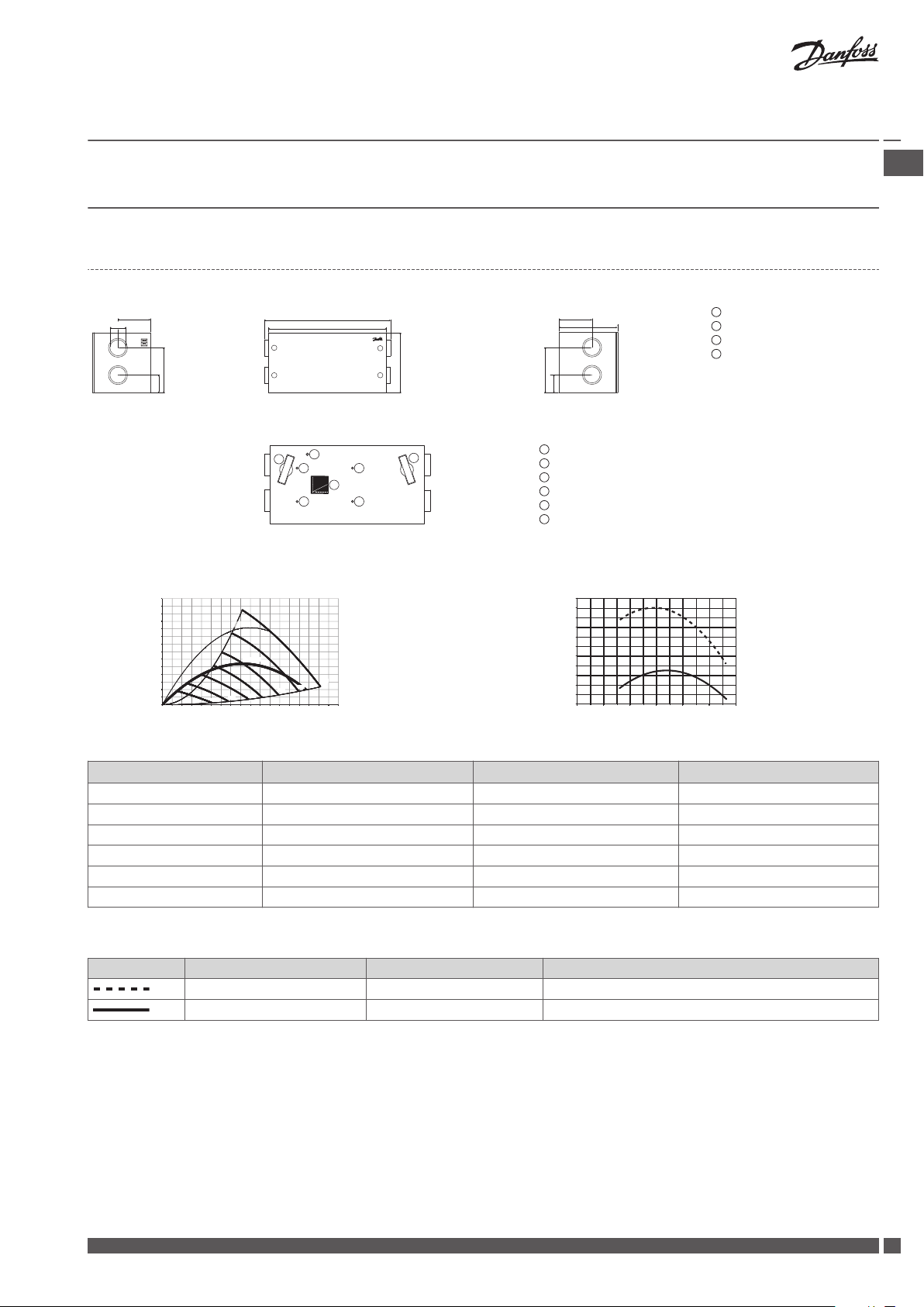
8 Technical Specifications
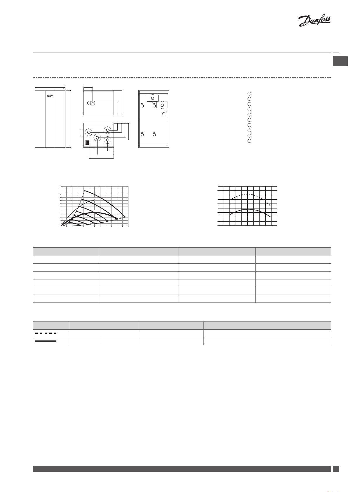
8.1 a² Unit
Dimensions
Front view (without front panel)
Filter, extract air
Filter, supply air
Flow chart (for balancing)
Filter reset button
Differential pressure for extract air
Differential pressure for supply air
GB .
Outdoor air
Exhaust air
Extract air
Supply air
Weight of unit: 52 kg
Capacity Temperature ratio
Pressure [Pa] η [%]
Flow [m³/h]
* 0.45 W/m³/h = "Passiv Haus" requirements.
Flow [m³/h] Pext. [Pa] SFP [J/m³] P1 tot. [W]
160 50 615 27
220 70 728 44
220 100 854 52
260 70 783 57
260 100 894 65
300 90 936 78
Tab. 3: Capacity for the a² unit
Extract air Fresh air
t = 21 °C RH = 36% t = -3 °C RH = 80% with condensation and 5% imbalance
t = 25 °C RH < 27% t = 5 °C as acc. to EN308
Flow [m³/h]
Tab. 4: Temperature ratio for the a² unit
Danfoss Heating Solutions VIEWB302
9

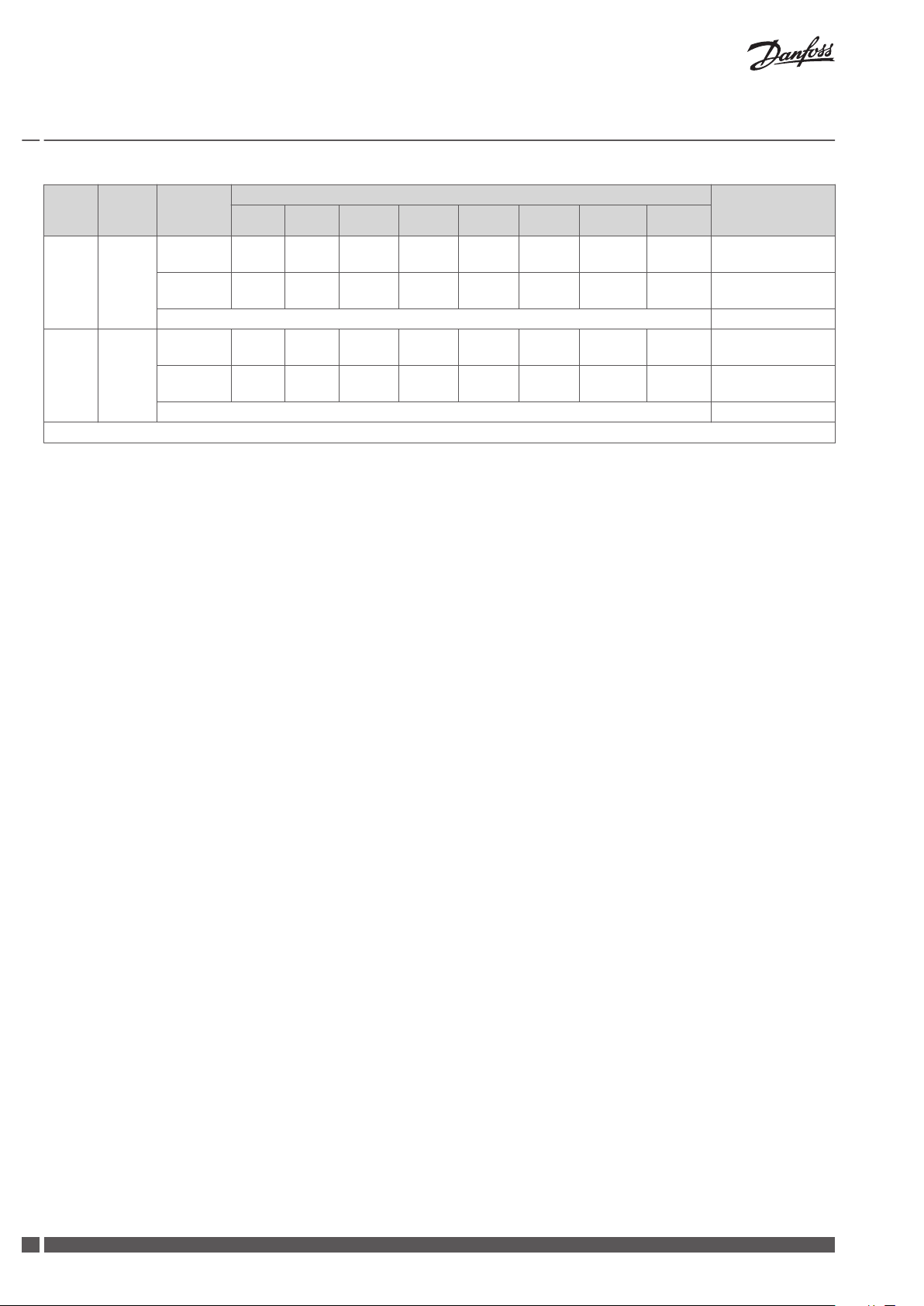
Installation Guide
Danfoss Air Units
Flow
m³/h
162 70
162 100
216 70
216 100
250 100
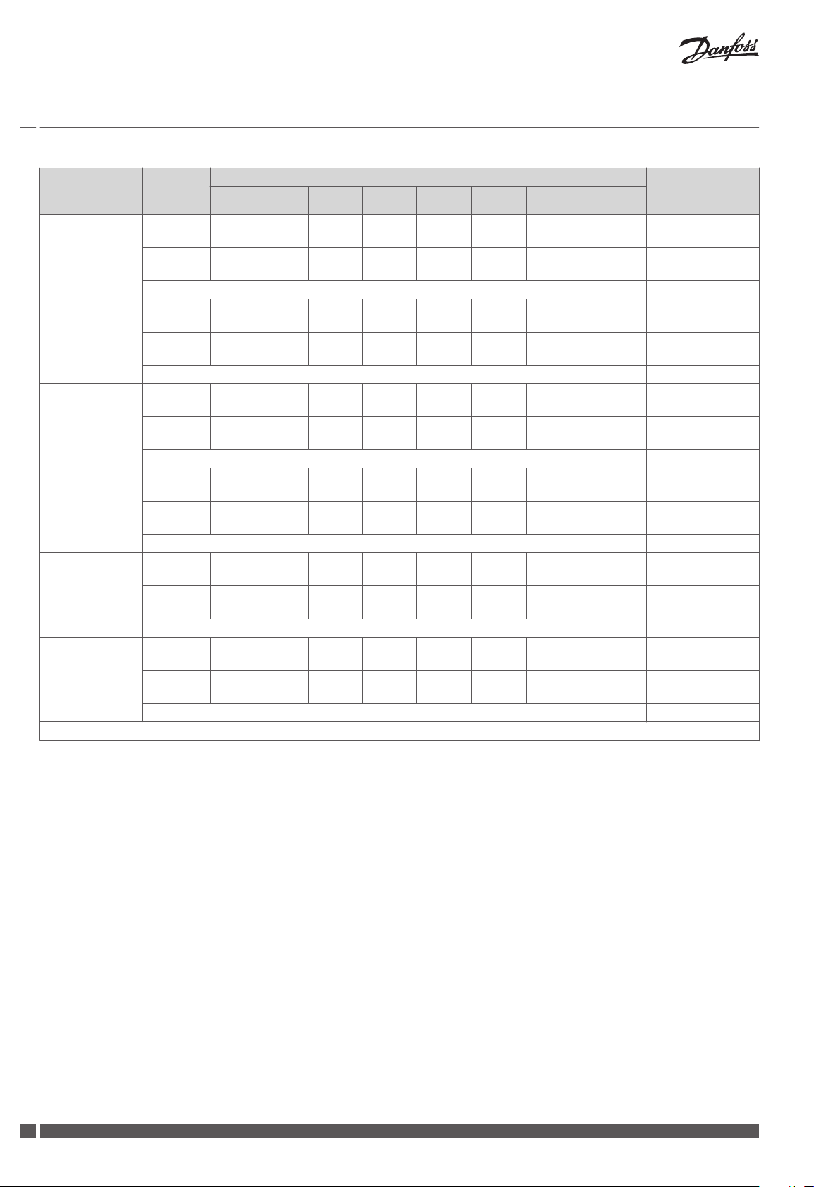
* Values for sound pressure calculated for a standard room with A = 10 m², H = 2.4m and mean absorption 0.2.
Pres-
sure Pa
Measured
at
Supply air
duct
Extract air
duct
Cabinet 40
Supply air
duct
Extract air
duct
Cabinet 41
Supply air
duct
Extract air
duct
Cabinet 45
Supply air
duct
Extract air
duct
Cabinet 46
Supply air
duct
Extract air
duct
Cabinet 49
63 125 250 500 1000 2000 4000 8000
23 34 40 36 29 25 17 18
23 33 39 37 29 24 18 18
25 35 43 38 31 28 18 18
25 36 42 39 30 25 17 18
26 36 44 39 33 30 19 18
28 36 43 41 34 29 18 18
26 37 44 40 34 31 19 18
27 37 45 42 35 30 19 18
28 39 46 42 37 33 21 18
30 39 48 45 38 33 20 18
Frequency band [Hz], sound power Lw (A) [dB(A)] Sound pressure
Lp(A) (standard*
room) [dB(A)]
Tab. 5: Sound data for the a² unit
10
VIEWB302 Danfoss Heating Solutions
250
440
160
528
318
1180
1342
600
1
2
3
4
780
440
160
528
318
1
2
3
4
1
2
3
4
5
6
6
5
1
2
3
4
5
6
40%
56%
82%
100%
1000 J/m³
300
250
200
150
100
50
0
0 50 100 150 200 250 300 350 400 450 500 550 600
*0.45 W/m³/h
80%
81%
82%
83%
84%
85%
86%
87%
88%
89%
90%
0 50 100 150 200 250 300 350 400 450 500
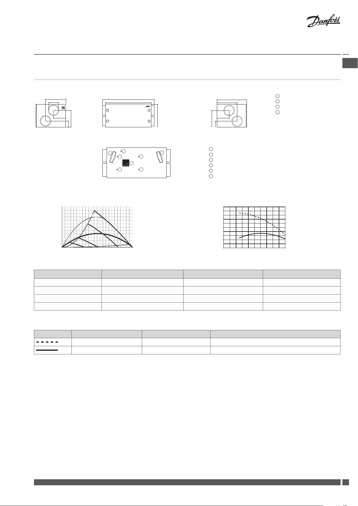
Installation Guide
Danfoss Air Units
8.2 a³ Unit
Dimensions
Outdoor air
Exhaust air
Extract air
Supply air
Weight of unit: 67 kg
Front view (without front panel)
Capacity Temperature ratio
Pressure [Pa] η [%]
Filter, extract air
Filter, supply air
Flow chart (for balancing)
Filter reset button
Differential pressure for extract air
Differential pressure for supply air
GB .
Flow [m³/h]
* 0.45 W/m³/h = "Passiv Haus" requirements.
Flow [m³/h] Pext. [Pa] SFP [J/m³] P1 tot. [W]
200 70 787 44
350 70 835 81
450 70 973 122
350 100 1000 97
Tab. 6: Capacity for the a³ unit
Extract air Fresh air
t = 21 °C RH = 36% t = -3 °C RH = 80% with condensation and 5% imbalance
t = 25 °C RH < 27% t = 5 °C as acc. to EN308
Tab. 7: Temperature ratio for the a³ unit
Flow [m³/h]
Danfoss Heating Solutions VIEWB302
11
Installation Guide
Danfoss Air Units
Flow
m³/h
350 70
450 100
* Values for sound pressure calculated for a standard room with A = 10 m², H = 2.4m and mean absorption 0.2.
Tab. 8: Sound data for the a³ unit
Pres-
sure Pa
Measured
at
Supply air
duct
Extract air
duct
Cabinet 57
Supply air
duct
Extract air
duct
Cabinet 61
63 125 250 500 1000 2000 4000 8000
35 45 56 49 47 44 31 16
35 44 54 48 48 44 31 19
39 48 62 55 52 50 37 22
39 47 61 55 53 48 37 20
Frequency band [Hz], sound power Lw (A) [dB(A)] Sound pressure
Lp(A) (standard*
room) [dB(A)]
12
VIEWB302 Danfoss Heating Solutions
530
1005
108
287
438
125
161
254
296
125
430
224
160
1
2
3
4
5
6
7
89
98
10
1
2
3
4
5
6
7
8
9
10
85%
70%
58%
46%
33%
21%
*0.45 W/m³/h
1000 J/m³
350
300
250
200
150
100
50
0
0 50 100 150 200 250 300
100%
84%
85%
86%
87%
88%
89%
90%
91%
92%
93%
0 50 100 150 200 250
Installation Guide
Danfoss Air Units
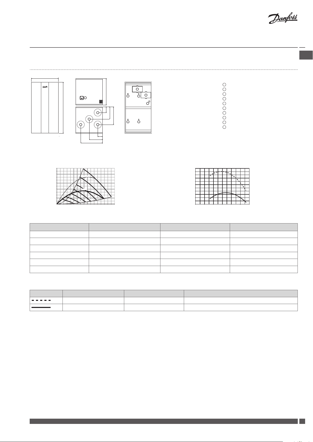
8.3 w¹ Unit
Supply air
Extract air
Exhaust air
Outdoor air
Condensate drain
Filter, extract air
Filter, supply air
Differential pressure for extract air
Differential pressure for supply air
Filter reset button
Weight of unit: 32 kg
Capacity Temperature ratio
Pressure [Pa] η [%]
GB .
Flow [m³/h]
* 0.45 W/m³/h = "Passiv Haus" requirements.
Flow [m³/h] Pext. [Pa] SFP [J/m³] P1 tot. [W]
100 35 588 16
100 55 682 19
140 60 710 28
140 70 759 30
180 70 798 40
180 100 945 47
Tab. 9: Capacity for the w¹ unit
Extract air Fresh air
t = 21 °C RH = 52% t = 5 °C RH = 80% with condensation and 5% imbalance
t = 25 °C RH < 27% t = 5 °C as acc. to EN308
Tab. 10: Temperature ratio for the w¹ unit
Flow [m³/h]
Danfoss Heating Solutions VIEWB302
13
Installation Guide
Danfoss Air Units
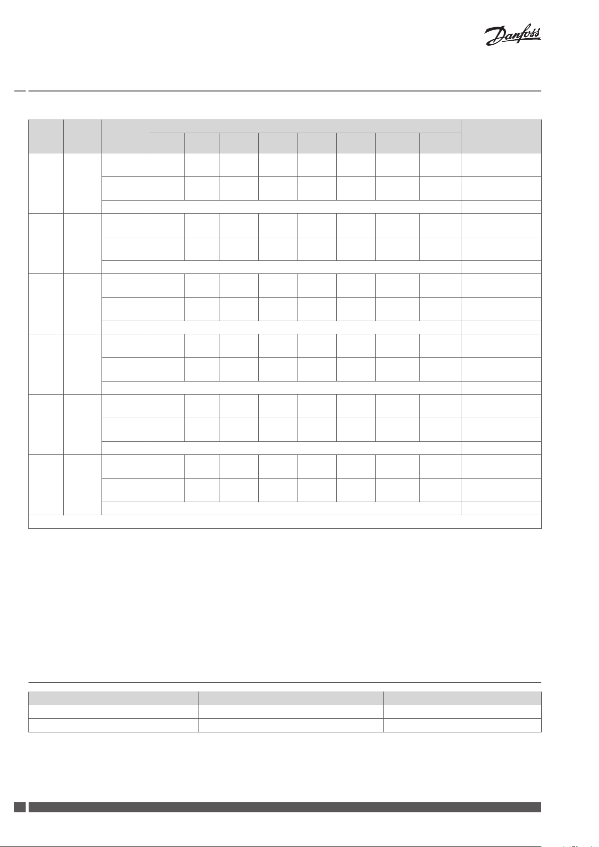
Flow
m³/h
126 70
126 100
162 70
162 100
216 70
216 100
* Values for sound pressure calculated for a standard room with A = 10 m², H = 2.4m and mean absorption 0.2.
Pres-
sure Pa
Measured
at
Supply air
duct
Extract air
duct
Cabinet 47
Supply air
duct
Extract air
duct
Cabinet 50
Supply air
duct
Extract air
duct
Cabinet 53
Supply air
duct
Extract air
duct
Cabinet 55
Supply air
duct
Extract air
duct
Cabinet 57
Supply air
duct
Extract air
duct
Cabinet 56
63 125 250 500 1000 2000 4000 8000
20 30 41 42 38 30 19 18
18 30 41 41 30 26 18 18
22 32 46 45 39 32 21 18
22 33 43 42 32 27 19 18
23 31 43 46 41 33 22 18
26 31 42 43 33 29 21 18
28 33 44 48 43 35 23 18
29 34 44 51 37 31 23 18
28 33 44 54 46 37 28 18
27 33 43 52 39 33 27 18
28 35 45 55 46 38 29 18
32 34 44 52 40 34 28 18
Frequency band [Hz], sound power Lw (A) [dB(A)] Sound pressure
Lp(A) (standard*
room) [dB(A)]
Tab. 11: Sound data for the w¹ unit
14
VIEWB302 Danfoss Heating Solutions
590
1055
580
126
270
389
110
295
480
1
2
3
4
5
6
7
8
9
98
10
1
2
3
4
5
6
7
8
9
10
100%
85%
70%
58%
46%
33%
21%
300
250
200
150
100
50
0
*0.45 W/m³/h
1000 J/m³
0 50 100 150 200 250 300 350 400
83%
84%
85%
86%
87%
88%
89%
90%
91%
92%
93%
94%
0 50 100 150 200 250 300
Installation Guide
Danfoss Air Units
8.4 w² Unit
Supply air
Extract air
Exhaust air
Outdoor air
Condensate drain
Filter, extract air
Filter, supply air
Differential pressure for extract air
Differential pressure for supply air
Filter reset button
Weight of unit: 45 kg
Capacity Temperature ratio
Pressure [Pa] η [%]
GB .
Flow [m³/h]
* 0.45 W/m³/h = "Passiv Haus" requirements.
Flow [m³/h] Pext. [Pa] SFP [J/m³] P1 tot. [W]
160 50 700 31
220 70 832 51
220 100 963 59
260 70 892 64
260 100 996 72
280 90 1000 78
Tab. 12: Capacity for the w² unit
Extract air Fresh air
t = 21 °C RH = 36% t = -3 °C RH = 80% with condensation and 5% imbalance
t = 25 °C RH < 27% t = 5 °C as acc. to EN308
Tab. 13: Temperature ratio for the w² unit
Flow [m³/h]
Danfoss Heating Solutions VIEWB302
15
Installation Guide Danfoss Air Units
Flow
m³/h
126 50
162 70
162 100
216 70
216 100
250 100
* Values for sound pressure calculated for a standard room with A = 10 m², H = 2.4m and mean absorption 0.2.
Pres-
sure Pa
Measured
at
Supply air
duct
Extract air
duct
Cabinet 39
Supply air
duct
Extract air
duct
Cabinet 44
Supply air
duct
Extract air
duct
Cabinet 46
Supply air
duct
Extract air
duct
Cabinet 47
Supply air
duct
Extract air
duct
Cabinet 49
Supply air
duct
Extract air
duct
Cabinet 53
63 125 250 500 1000 2000 4000 8000
20 30 34 36 23 19 17 18
16 31 37 36 29 21 17 18
23 33 35 40 32 24 18 18
20 33 44 39 34 26 18 18
25 36 42 42 34 28 18 18
21 33 43 41 35 28 18 18
25 34 42 42 35 28 19 18
22 34 44 43 37 31 20 18
26 36 43 44 36 30 20 18
23 34 45 44 33 32 20 18
27 36 45 45 38 31 21 18
24 37 47 45 40 34 22 18
Frequency band [Hz], sound power Lw (A) [dB(A)] Sound pressure
Lp(A) (standard*
room) [dB(A)]
Tab. 14: Sound data for the w² unit
9 Troubleshooting
Error Cause Solution
Alarm: Filter error Air filters are dirty. Exchange air filters and reset alarm.
Alarm: Battery low Battery voltage in Air Dial is too low. Replace batteries (4 x AAA) in Air Dial.
16
VIEWB302 Danfoss Heating Solutions
Installation Guide Danfoss Air Units
Error Cause Solution
Alarm: No connection to CCM/link test
failed
Alarm: No connection via modbus/link test
failed
Alarm: Room air too cold Central heating system is not supplying heat.
Alarm: Fire One of four temperature sensors in Danfoss Air
Alarm: Sensor error Temperature sensor in Danfoss Air unit or Air
Abnormally large negative pressure inside
the house, doors binding
Condensation in window frames Air exchange is too low. Condensation occurs
House temperatures are too high House thermostats are set too high. Turn down thermostats.
Bypass is disabled on ventilation system. Bypass is disabled on ventilation system. Enable Bypass in Main menu Bypass
Noise from Air Unit a-type unit: vibration noise may occur if unit is
Communication between Air Dial and CCM
module has failed, typically caused by an obstacle between Air Dial and CCM module, e.g.
steel piping, other steel objects, insulation material clad with aluminum foil, etc. Another
cause can be other wireless appliances that
does not conform to wireless standards (radio
noise).
Cable between CCM module and unit is unplugged or defective.
Room temperature is dropping, so the unit
turn off to reduce involuntary heat loss. Alarm
active if Air Dial measures a room temperature
below +10 °C.
Unit or temperature sensor in Air Dial remote
control has detected a temperature higher
than +70 °C. The Air Unit turns off until all sensors indicate below +70 °C.
Dial is defective.
Discharge air flow is larger than supply air flow.
Either balancing was not carried out correctly
during set-up of the system or the Air Unit is in
extreme defrost conditions (can occur at outdoor temperatures below -12 °C).
when humidity is high and surface temperatures are low, typically in bathrooms or utility
rooms, where clothes are drip drying (some
condensation in bathrooms following a shower
is normal, but should disappear within half an
hour).
mounted directly onto joists. Unit should be
mounted on a suitable platform.
w-type unit: vibration noise may occur if rubber spacers are not fitted between unit and
wall and/or if silicone strip is not fitted onto
wall bracket.
Defective fan bearings will produce a ‘grinding
noise’.
If an obstacle has been identified, move
it. If this is not possible, move CCM
module to a better location with a free
‘line of sight’.
If the error occurs due to other wireless
appliances in the house, try switching
these off one by one, to identify the
faulty device.
If none of the above helps, contact Danfoss.
Check cable and reconnect if necessary.
If cable is connected, but error still occurs - contact Danfoss.
Check if heating system is functional. If
the problem can not be solved, contact
plumber/Danfoss.
When error has been remedied, shut
down and restart ventilation system to
resume normal operation. Power can be
disconnected by pulling power cable
from system.
Examine all rooms, leave the house.
When error has been remedied, shut
down and restart ventilation system to
resume normal operation. Power can be
disconnected by pulling power cable
from system.
Contact Danfoss.
System continues to run, but with limited functionality.
Imbalance of flow should be 4-10% in
favour of extract air, but if problems
with doors binding is permanent, contact Danfoss.
If problems only arises during extreme
winter condition, it is due to the integrated defrost function that reduces the
supply air (hence not a defect, but an
expected, and very rare occurrence).
Increase fan step Manual mode or
change to Demand mode or Pro-
gramme mode.
Set Autoboost - on.
Auto bypass.
Check that unit is mounted on platform,
according to installation manual.
Check that rubber spacers and silicone
strip are fitted, according to installation
manual.
If fan ball bearing is suspected to be defective, contact Danfoss.
GB .
Danfoss Heating Solutions VIEWB302
17
Installation Guide Danfoss Air Units
Error Cause Solution
Noise from Air valves Air flow is too high. Noise is not a problem in a correctly
sized and commissioned system. However, if air valves are closed (e.g. during
cleaning), a hissing noise may occur.
This is not an error, but a standard
mode. The function stops automatically
when the outdoor temperature rises.
Frost icon in display
Pressure is too high over valve.
No silencer is fitted to main duct.
The system is in defrost mode, because low
outdoor temperatures entail a risk of ice forming in the heat exchanger.
18
VIEWB302 Danfoss Heating Solutions

Installationsvejledning Danfoss Air ventilationsanlæg
Indholdsfortegnelse
1 Sikkerhedsnoter ................................................................. 19
2 Før du starter ................................................................... 19
3 Installation af Air Units ............................................................ 20
4 Installation af CCM-modul og Air Dial .................................................. 21
4.1 Elektriske tilslutninger .......................................................... 21
4.2 Trådløs forbindelse ............................................................ 21
4.3 Air Dial .................................................................... 21
4.4 Montering og afmontering af CCM-modul og Air Dial ...................................... 22
5 Tilslutning til Danfoss Link™ CC ....................................................... 22
5.1 Tilslutning af Air-enheden til Danfoss Link™ CC, fysisk installation .............................. 22
5.2 Tilslutning af Air-enheden til Danfoss Link™ CC, trådløs tilslutning .............................. 22
5.3 Udførelse af en netværkstest efter tilføjelse af en ny enhed .................................. 23
5.4 Indstilling af grundtrin i Danfoss Link™ CC ............................................. 24
6 Afbalancering af hovedluftmængden .................................................. 24
7 Servicemenu ................................................................... 25
8 Tekniske specifikationer ........................................................... 26
8.1 a²-enhed ................................................................... 26
8.2 a³-enhed ................................................................... 28
8.3 w¹ enhed ................................................................... 30
8.4 w² enhed .................................................................. 32
9 Fejlfinding ..................................................................... 33
DK .
1 Sikkerhedsnoter
Dette apparat er ikke beregnet til at blive brugt af personer (herunder børn) med nedsat fysisk, sansemæssig eller psykisk formåen eller
med manglende erfaring og viden, medmindre de er under opsyn eller er blevet instrueret i brugen af apparatet af en person, der er
ansvarlig for deres sikkerhed.
Børn skal være under opsyn for at sikre, at de ikke leger med apparatet.
Ud over at skifte luftfilter og rengøre anlægget udvendigt, vil enhver form for service kræve uddannet personale.
2 Før du starter
Kontroller venligst, at leveringen af Danfoss Air-enheden er komplet ifølge følgesedlen.
Hvis du har bestilt en komplet Danfoss Air-løsning, medfølger der en komplet følgeseddel for Air Flex-kanalsystemet.
Kontroller dele og elementer for at sikre dig, at intet er beskadiget.
Bemærk! Danfoss Air Flex-kanaler er omfattet af gældende dansk lovgivning, og der henvises til:
Dansk Standard DS 428: Norm for brandtekniske foranstaltninger ved ventilationssystemer.
▪
Dansk Standard DS 447: Norm for mekaniske ventilationsanlæg.
▪
Standardlevering omfatter:
Danfoss Air-enhed
▪
Vægbeslag (hvis w-model)
▪
CCM
▪
Kabler
▪
Valgfri leveringer:
Air Dial
▪
▪
Danfoss LinkTM CC
Danfoss Heating Solutions VIEWB301
19
2
1
2
3
4
5
6
1
1 cm
2
75 mm
1
2
3
4
5
6
Installationsvejledning Danfoss Air ventilationsanlæg
3 Installation af Air Units
Loftsenhed a² og a³
1. Træk studsene ud 1. Løft aldrig anlægget i studsene, da det kan skade anlægget.*
2. Vend studsene om, og monter dem vha. de medfølgende pladeskruer (til skruemaskine, brug
laveste momentindstilling).
3. Lav en platform
batts.
4. Beregn 60 cm fri plads foran enheden, så der sikres adgang i forbindelse med service.
5. Sørg for, at enheden monteres med et lille bagfald.
6. Der skal altid monteres en vandlås 5 til enheden (bestilles separat).
7. Monter vandlåsen på spæret 4 under enheden, eller monter den i rummet under loftsrummet.
8. Forbind vandlåsen til et afløb 6.
9. Kondensledningen 3 skal være isoleret, hvor der er risiko for frost.
10. Forbind slangen til kondensudløbsstudsen på enheden. Før den tilsluttede slange til afløb,
og sørg for en hældning på min. 1 cm/meter.
11. Fjern frontpanelet og skumfronten, fyld kondensbakken, kontroller afløbsfunktionen og saml
fronten igen.
* Løftes anlægget i studsene kan der opstå utæthed mellem stålkabinet og polystyrenkernen. Utætheden kan udbedres ved at fuge studsene indefra med en akrylbaseret tætningsmasse.
til enheden af 16 mm-krydsfiner eller MDF-plader omkring 50 mm-mur-
Vægenhed w¹ og w²
1. Placer monteringsbeslaget 1 på den ønskede placering på væggen (75 mm fra bunden af
beslaget til toppen af enheden), mærk af og bor huller. Anvend skruer, der er egnet til vægoverfladen (skruer medfølger ikke).
2. Sørg for, at beslaget er monteret fuldstændigt i vatter.
3. Hæng enheden på beslaget.
4. Monter de selvklæbende gummiafstandsstykker
på den nederste, bagerste bagplade.
5. Beregn 60 cm fri plads foran enheden, så der sikres adgang i forbindelse med service.
6. Der skal altid monteres en vandlås 3 til enheden (bestilles separat).
7. Monter vandlåsen på væggen under enheden.
8. Slut vandlåsen til afløbet 5 i bunden af enheden.
9. Kondensledningen 4 skal være isoleret, hvor der er risiko for frost.
10. Forbind slangen til kondensudløbsstudsen på enheden. Før den tilsluttede slange til afløb,
og sørg for en hældning på min. 1 cm/meter.
11. Fjern frontpanelet og skumfronten, fyld kondensbakken, kontroller afløbsfunktionen og saml
fronten igen.
Væganlæg w¹
For at overholde sikkerhedsstandarderne og undgå risikoen for funktionsfejl, skal det medfølgende beskyttelsesskjold monteres oven på w¹-enheden, så det dækker forbindelsespladen.
20
VIEWB301 Danfoss Heating Solutions

1
2
3
4
5
6
1
2
3
4
!
Installationsvejledning Danfoss Air ventilationsanlæg
4 Installation af CCM-modul og Air Dial
4.1 Elektriske tilslutninger
1. Slut forsyningsledningen 4 til Air-enheden 3.
2. Tilslut CCM-kablet 2 mellem CCM-modulet 1 og Air-enheden.
3. Kontroller signalet. Hvis det er for svagt, skal CCM-modulet placeret et andet sted, fx på
samme etage som Air Dial (se afsnittet Linktest af Air Dial).
4. Hvis det er muligt, skal CCM-modulet placeres tæt på en ethernet-forbindelse for senere
tilslutning til en pc.
5. Hvis der findes tilbehør (elforvarme, eleftervarme, vandvarmeflade eller geotermisk flade)
skal lusen på klemme 5 og 6 fjernes (se også vejledningen, der følger med tilbehøret).
Stik på CCM-kabelet:
1. Hvid/orange, 2. Orange, 3. Sort, 4. Hvid/blå, 5. Blå, 6. Sort
Bemærk! CCM-kabelet kan forlænges til op til 200 m. Brug skærmet kabel på 22 eller 24 AWG med 2 x parsnoet.
4.2 Trådløs forbindelse
Når CCM-modulet startes, vil den grønne lysdiode blinke langsomt. Dette angiver, at CCM-modulet ikke er tilsluttet Air Dial endnu.
For at tilslutte Air Dial sættes batterier i. Air Dial starter i installationstilstand og fører automatisk
installatøren gennem opsætningen.
1. Indstil sprog.
2. Opret netværk (tryk på knappen på CCM-modulet, og tryk derefter på Air Dial).
3. Indstil basistrin (opsætning af hovedluftmængde).
4. Afslut.
DK .
Grøn lysdiode lyser konstant Forbindelse etableret
Rød lysdiode blinker langsomt fem gange Forsøg på tilslutning mislykkedes, se afsnittet Fejlfinding.
Tab. 2: Mønstre for blinkende lysdioder på CCM
4.3
Air Dial
Air Dial har en integreret temperaturføler. For at sikre bedst mulig ydeevne skal Air Dial
placeres i henhold til følgende retningslinjer:
Placer Air Dial 80-150 cm over gulvet.
▪
Placer Air Dial væk fra gardiner osv.
▪
Placer Air Dial, hvor temperaturen er repræsentativ.
▪
Placer ikke Air Dial på badeværelser.
▪
Air Dial må ikke placeres i direkte sollys.
▪
Air Dial må ikke placeres på en ydervæg.
▪
Air Dial må ikke placeres direkte over en varmekilde.
▪
Danfoss Heating Solutions VIEWB301
21

2
1
2
1
1
1
2
1
2
1
2
3
4
5
6
1
2
3
4
Installationsvejledning Danfoss Air ventilationsanlæg
Air Dial Link Test
Inden Air Dial monteres permanent, skal der udføres en linktest for at sikre, at sendeforholdene er tilstrækkelige for den nødvendige
placering:
1. Tryk på Air Dial-knappen i 5 sekunder for at få adgang til Servicemenuen(Servicemenuen er synlig i en time).
2. Vælg funktionen Link Test.
3. Funktionen viser, om sendeforholdene er tilstrækkelige.
4. Hvis link testen ikke lykkes, skal du se fejlfinding.
4.4 Montering og afmontering af CCM-modul og Air Dial
CCM-modul
Montering:
1. Placer CCM-modulet på vægbeslaget.
2. Tryk nedad for at klikke CCM
på plads.
Air Dial
Montering:
1. Placer Air Dial på vægbeslaget.
2. Tryk nedad for at klikke Air
Dial på plads.
Afmontering:
1. Tryk de to paler på siden ind.
2. Træk CCM opad.
Afmontering:
1. Løft Air Dial op.
2. Træk Air Dial væk.
5 Tilslutning til Danfoss Link™ CC
5.1 Tilslutning af Air-enheden til Danfoss Link™ CC, fysisk installation
1. Slut forsyningsledningen 4 til Air-enheden 3.
2. Tilslut CCM-kablet 2 mellem CCM-modulet 1 og Air-enheden.
3. Hvis det er muligt, skal CCM-modulet placeres tæt på en ethernet-forbindelse for senere
tilslutning til en PC.
4. Hvis der findes tilbehør (elforvarme, eleftervarme, vandvarmeflade eller geotermisk flade)
skal lusen på klemme 5 og 6 fjernes (se også vejledningen, der følger med tilbehøret).
5. Air-enheden er nu klar til at blive tilføjet til Danfoss Link™ CC.
Stik på CCM-kablet:
1. Hvid/orange, 2. Orange, 3. Sort, 4. Hvid/blå, 5. Blå, 6. Sort
Bemærk! CCM-kablet kan forlænges til op til 200 m. Brug skærmet kabel på 22 eller 24 AWG med 2 x parsnoet.
5.2 Tilslutning af Air-enheden til Danfoss Link™ CC, trådløs tilslutning
Fjern frontpanelet på Danfoss Link™ CC ved forsigtigt at trække det af. Træk nær kanter-
▪
ne af panelet.
Tryk på knappen Setup i tre sekunder for at åbne serviceområdet.
▪
22
VIEWB301 Danfoss Heating Solutions

?
1
Service-funktioner
Rum og enheder
?
2
Rum og enheder
Tilføj service-enhed
?
3
Tilføj service-enhed
Start registrering
?
1
Service-funktioner
Status og fejlnding
?
2
Status og fejlnding
Netværk
?
3
Status for trådløst netværk
Start netværkstest
Installationsvejledning
Danfoss Air ventilationsanlæg
Bemærk!
Air-enheden skal tilføjes til netværket som en serviceenhed. For yderligere vejledning om netværkstilslutning, se den medfølgende instal-
▪
lationsvejledning til Danfoss Link™ CC.
Tilføj eventuelle dedikerede repeater-enheder (CF-RU) FØR tilføjelse af Air-enheden til det trådløse netværk.
▪
Klik her for at tilføje CCM-modulet til Air-en-
heden
Bemærk! Under installation må afstanden mellem Danfoss Link™ CC og CCM ikke overstige 1,5 meter.
Grøn lysdiode blinker langsomt
CCM-modulet er endnu ikke tilsluttet til Danfoss Link™ CC
Grøn lysdiode lyser konstant CCM-modulet er nu tilsluttet til Danfoss Link™ CC
Rød lysdiode blinker langsomt fem gange Forsøg på tilslutning mislykkedes
Tab. 2: Mønstre for blinkende lysdioder på CCM
DK .
5.3
Udførelse af en netværkstest efter tilføjelse af en ny enhed
Efter færdiggørelsen af installationen skal der udføres en netværkstest for at sikre, at kommunikationen mellem alle tilføjede enheder og
Danfoss Link CC™ er stabil.
Bemærk! Udfør ikke netværkstesten, før Danfoss Link™ CC er monteret på sin endelige placering.
Ved afslutningen af netværkstesten afventer Danfoss Link™ CC, at alle batteridrevne enheder aktiveres og registreres. Følg anvisningerne
på skærmen. Hvis netværkstesten kører uden problemer, vil der ikke være behov for yderligere interaktion. Hvis netværkstesten kører
langsomt, guider Danfoss Link™ CC dig gennem fejlfinding og giver nyttige tips til, hvordan processen gøres hurtigere.
Danfoss Heating Solutions VIEWB301
23

?
1
Service-funktioner
Rum og enheder
?
2
Rum og enheder
Håndter enheder
?
3
Håndter enheder
Kongurer enhed
?
4
Vælg Enhed
Ventilationsanlæg
?
5
Kongurer Enhed
Systemindstillinger
?
6
Systemindstillinger
Juster basistrin
Installationsvejledning Danfoss Air ventilationsanlæg
5.4 Indstilling af grundtrin i Danfoss Link™ CC
Nu er Air-enheden tilføjet til det trådløse system og er klar til afbalancering af luftstrømningen. Hvis Air-enheden netop er blevet tilføjet
til systemet, vil skærmen anmode om indstilling af grundtrin for udsugnings- og indblæsningsluft.
Hvis systemet blev startet tidligere/af andre, indtastes de grundlæggende indstillinger ved hjælp af Servicemenuen ved at trykke på Air
Dial-knappen i 5 sekunder. Gennemgå følgende trin:
6 Afbalancering af hovedluftmængden
For at opnå den bedst mulige ydeevne er det afgørende, at hovedluftmængderne indreguleres
(dette vil bidrage til at beskytte huset mod svamp og råd). Systemet bør ikke indreguleres ved
udetemperaturer under -3 °C, da det vil gå i frostbeskyttelsestilstand (angives ved et blinkende
ikon på displayet). Hvis indregulering er nødvendig ved udelufttemperaturer under -3 °C, skal
strømforsyningen fjernes i 20 sekunder for at deaktivere frostbeskyttelsen i 90 minutter.
Bemærk! Luk alle døre, og sluk for emhætten.
1. Fjern frontpanelet fra enheden ved at trække i håndtagene.
2. Se tegningen af kanalsystemet, hvor du finder de foreslåede forindstillingsværdier for alle
luftventiler. Luk ventilerne helt, og drej dem derefter hele omdrejninger rundt mod "åben"
(antal omdrejninger som angivet på tegningen af kanalsystemet). Ved indregulering af systemer hvor Danfoss ikke har dimensioneret kanalsystemet, indstilles indblæsnings- og udsugningsventiler iht. den projekteringsansvarliges anvisninger.
3. Hvis der indgår spjæld i systemet, åbnes disse helt.
4. Monter måleslanger mellem enhedens målepunkter på udsugningssiden og differenstrykmåleren.
5. Find den påkrævede gennemstrømning på systemdiagrammet (klistermærke på fronten)
med den tilsvarende differenstrykværdi. Hvis trykket er for lavt, reguleres ventilatortrinet
op, indtil det ønskede tryk opnås.
6. Flyt måleslangerne til målepunkterne på indblæsningssiden, og benyt samme fremgangsmåde for indstilling af indblæsningsluften.
7. Når hovedluftmængderne er indreguleret, skal der foretages en indregulering på de enkelte ventiler. Dette vil i de fleste tilfælde medføre mindre ændringer på de valgte grundtrin,
men dette kan gøres i rummet vha. regulering af ventilerne eller ved at bruge Air Dial til at
finjustere grundtrinnene.
Måling af udsugning
Justering af et system i drift
1. Tryk på Air Dial i 5 sekunder for at få adgang til servicemenuen.
2. Tryk på "Basistrin" for at aktivere den specielle indreguleringstilstand (hvor alle udefrakommende påvirkninger blokeres – installatøren styrer udsugnings- og indblæsningsventilatoren helt med 1-100 % ventilatorhastighed).|| Servicemenuen vil forblive synlig i en time,
hvorefter den vil forsvinde.
24
Måling af indblæsning
VIEWB301 Danfoss Heating Solutions

Service
Tilbage
Info
Filter
Sprog
Basis trin
Link test
Tilbehør
Installationsvejledning Danfoss Air ventilationsanlæg
7 Servicemenu
Tryk på Air Dial i 5 sekunder for at få adgang til Servicemenuen for at ændre grundlæggende
indstillinger, såsom sprog, filtertimer, grundtrin osv.
Nulstilling af system
1. Hvis systemet allerede er indreguleret, skal ventilatorgrundtrinene noteres til senere brug.
Værdierne kan findes i Servicemenuen: Service > Info > Basistrin.
2. Fjern og isæt batterierne til Air Dial igen, mens der trykkes på knappen, indtil der høres et
bip. Air Dial befinder sig nu i opstartstilstand.
3. Fjern forsynings- eller CCM-kablet.
4. Mens kablet tilsluttes igen, trykkes der på CCM-modulknappen, indtil den grønne lysdiode
blinker.
5. Systemet er nu nulstillet til fabriksindstillingerne.
DK .
Danfoss Heating Solutions VIEWB301
25

450
325
177
160
1263
1180
600
1
2
3
4
580
450
325
177
1
2
3
4
1
2
3
4
5
6
6
5
1
2
3
4
5
6
100%
85%
1000 J/m³
70%
58%
46%
33%
21%
350
300
250
200
150
100
50
0
0 50 100 150 200 250 300 350 400 450
*0.45 W/m³/h
83%
84%
85%
86%
87%
88%
89%
90%
91%
92%
93%
94%
0 50 100 150 200 250 300
Installationsvejledning
Danfoss Air ventilationsanlæg
8 Tekniske specifikationer
8.1 a²-enhed
Dimensioner
Set forfra (uden frontpanel)
Filter, udsugning fra rum
Filter, indblæsning
Flowdiagram (til indregulering)
Reset-knap til filter
Differenstrykudtag for udsugning fra rum
Differenstrykudtag for indblæsning til rum
Udeluft
Afkastluft
Udsugning fra rum
Indblæsning
Enhedens vægt: 52 kg
Kapacitet Virkningsgrad
Eksternt tryk [Pa] η [%]
Luftmængde [m³/h]
Luftmængde [m³/h]
* 0,45 Wh/m³ = "Passiv Haus"-krav
Luftmængde [m³/h] Pext. [Pa] SEL [J/m³] P1 tot. [W]
160 50 615 27
220 70 728 44
220 100 854 52
260 70 783 57
260 100 894 65
300 90 936 78
Tab. 3: Kapacitet for a²-enhed
Udsugning fra rum Udeluft
t = 21 °C RH = 36 % t = -3 °C RH = 80 % med kondens og 5 % ubalance
t = 25 °C RH < 27 % t = 5 °C iht. EN308
Tab. 4: Luftkonditioner for virkningsgrader for a²-enheden
26
VIEWB301 Danfoss Heating Solutions

Installationsvejledning
Danfoss Air ventilationsanlæg
Luftmæng-
de [m³/h]
162 70
162 100
216 70
216 100
250 100
* Værdier for lydtryk beregnet for et standardrum med A = 10 m², H = 2,4 m og gennemsnitlig dæmpning 0,2.
Tryk
[Pa]
Målt ved:
Indblæsningskanal
Udsugningskanal
Kabinet 40
Indblæs-
ningskanal
Udsugnings-
kanal
Kabinet 41
Indblæs-
ningskanal
Udsugnings-
kanal
Kabinet 45
Indblæs-
ningskanal
Udsugnings-
kanal
Kabinet 46
Indblæs-
ningskanal
Udsugnings-
kanal
Kabinet 49
63 125 250 500 1000 2000 4000 8000
23 34 40 36 29 25 17 18
23 33 39 37 29 24 18 18
25 35 43 38 31 28 18 18
25 36 42 39 30 25 17 18
26 36 44 39 33 30 19 18
28 36 43 41 34 29 18 18
26 37 44 40 34 31 19 18
27 37 45 42 35 30 19 18
28 39 46 42 37 33 21 18
30 39 48 45 38 33 20 18
Frekvensbånd [Hz], lydeffekt Lw (A) [dB(A)]
Lydtryk Lp(A) (stan-
dard* rum) [dB(A)]
DK .
Tab. 5: Lyddata for a²-enhed
Danfoss Heating Solutions VIEWB301
27

250
440
160
528
318
1180
1342
600
1
2
3
4
780
440
160
528
318
1
2
3
4
1
2
3
4
5
6
6
5
1
2
3
4
5
6
40%
56%
82%
100%
1000 J/m³
300
250
200
150
100
50
0
0 50 100 150 200 250 300 350 400 450 500 550 600
*0.45 W/m³/h
80%
81%
82%
83%
84%
85%
86%
87%
88%
89%
90%
0 50 100 150 200 250 300 350 400 450 500
Installationsvejledning
Danfoss Air ventilationsanlæg
8.2 a³-enhed
Dimensioner
Udeluft
Afkastluft
Udsugning fra rum
Indblæsning
Enhedens vægt: 67 kg
Set forfra (uden frontpanel)
Kapacitet Virkningsgrad
Eksternt tryk [Pa] η [%]
Filter, udsugning fra rum
Filter, indblæsning
Flowdiagram (til indregulering)
Reset-knap til filter
Differenstrykudtag for udsugning fra rum
Differenstrykudtag for indblæsning til rum
Luftmængde [m³/h]
Luftmængde [m³/h]
* 0,45 Wh/m³ = "Passiv Haus"-krav
Luftmængde [m³/h] Pext. [Pa] SEL [J/m³] P1 tot. [W]
200 70 787 44
350 70 835 81
450 70 973 122
350 100 1000 97
Tab. 6: Kapacitet for a³-enhed
Udsugning fra rum Udeluft
t = 21 °C RH = 36 % t = -3 °C RH = 80 % med kondens og 5 % ubalance
t = 25 °C RH < 27 % t = 5 °C iht. EN308
Tab. 7: Luftkonditioner for virkningsgrader for a³-enhed
28
VIEWB301 Danfoss Heating Solutions

Installationsvejledning
Danfoss Air ventilationsanlæg
Luftmæng-
de [m³/h]
350 70
450 100
* Værdier for lydtryk beregnet for et standardrum med A = 10 m², H = 2,4 m og gennemsnitlig dæmpning 0,2.
Tab. 8: Lyddata for a³-enhed
Tryk
[Pa]
Målt ved:
Indblæsningskanal
Udsugningskanal
Kabinet 57
Indblæs-
ningskanal
Udsugnings-
kanal
Kabinet 61
63 125 250 500 1000 2000 4000 8000
35 45 56 49 47 44 31 16
35 44 54 48 48 44 31 19
39 48 62 55 52 50 37 22
39 47 61 55 53 48 37 20
Frekvensbånd [Hz], lydeffekt Lw (A) [dB(A)]
Lydtryk Lp(A) (stan-
dard* rum) [dB(A)]
DK .
Danfoss Heating Solutions VIEWB301
29

530
1005
108
287
438
125
161
254
296
125
430
224
160
1
2
3
4
5
6
7
89
98
10
1
2
3
4
5
6
7
8
9
10
85%
70%
58%
46%
33%
21%
*0.45 W/m³/h
1000 J/m³
350
300
250
200
150
100
50
0
0 50 100 150 200 250 300
100%
84%
85%
86%
87%
88%
89%
90%
91%
92%
93%
0 50 100 150 200 250
Installationsvejledning
Danfoss Air ventilationsanlæg
8.3 w¹ enhed
Indblæsning
Udsugning fra rum
Afkastluft
Udeluft
Kondensafløb
Filter, udsugning fra rum
Filter, indblæsning
Differenstrykudtag for udsugning fra
rum
Differenstrykudtag for indblæsning til
rum
Reset-knap til filter
Enhedens vægt: 32 kg
Kapacitet Virkningsgrad
Eksternt tryk [Pa] η [%]
Luftmængde [m³/h]
Luftmængde [m³/h]
* 0,45 Wh/m³ = "Passiv Haus"-krav
Luftmængde [m³/h] Pext. [Pa] SEL [J/m³] P1 tot. [W]
100 35 588 16
100 55 682 19
140 60 710 28
140 70 759 30
180 70 798 40
180 100 945 47
Tab. 9: Kapacitet for w¹-enhed
Udsugning fra rum Udeluft
t = 21 °C RH = 52 % t = 5 °C RH = 80 % med kondens og 5 % ubalance
t = 25 °C RH < 27 % t = 5 °C iht. EN308
Tab. 10: Luftkonditioner for virkningsgrader for w¹-enheden
30
VIEWB301 Danfoss Heating Solutions

Installationsvejledning
Danfoss Air ventilationsanlæg
Luftmæng-
de [m³/h]
126 70
126 100
162 70
162 100
216 70
216 100
* Værdier for lydtryk beregnet for et standardrum med A = 10 m², H = 2,4 m og gennemsnitlig dæmpning 0,2.
Tryk
[Pa]
Målt ved:
Indblæsningskanal
Udsugningskanal
Kabinet 47
Indblæs-
ningskanal
Udsugnings-
kanal
Kabinet 50
Indblæs-
ningskanal
Udsugnings-
kanal
Kabinet 53
Indblæs-
ningskanal
Udsugnings-
kanal
Kabinet 55
Indblæs-
ningskanal
Udsugnings-
kanal
Kabinet 57
Indblæs-
ningskanal
Udsugnings-
kanal
Kabinet 56
63 125 250 500 1000 2000 4000 8000
20 30 41 42 38 30 19 18
18 30 41 41 30 26 18 18
22 32 46 45 39 32 21 18
22 33 43 42 32 27 19 18
23 31 43 46 41 33 22 18
26 31 42 43 33 29 21 18
28 33 44 48 43 35 23 18
29 34 44 51 37 31 23 18
28 33 44 54 46 37 28 18
27 33 43 52 39 33 27 18
28 35 45 55 46 38 29 18
32 34 44 52 40 34 28 18
Frekvensbånd [Hz], lydeffekt Lw (A) [dB(A)]
Lydtryk Lp(A) (stan-
dard* rum) [dB(A)]
DK .
Tab. 11: Lyddata for w¹-enheden
Danfoss Heating Solutions VIEWB301
31

590
1055
580
126
270
389
110
295
480
1
2
3
4
5
6
7
8
9
98
10
1
2
3
4
5
6
7
8
9
10
100%
85%
70%
58%
46%
33%
21%
300
250
200
150
100
50
0
*0.45 W/m³/h
1000 J/m³
0 50 100 150 200 250 300 350 400
83%
84%
85%
86%
87%
88%
89%
90%
91%
92%
93%
94%
0 50 100 150 200 250 300
Installationsvejledning
Danfoss Air ventilationsanlæg
8.4 w² enhed
Indblæsning
Udsugning fra rum
Afkastluft
Udeluft
Kondensafløb
Filter, udsugning fra rum
Filter, indblæsning
Differenstrykudtag for udsugning fra
rum
Differenstrykudtag for indblæsning til
rum
Reset-knap til filter
Enhedens vægt: 45 kg
Kapacitet Virkningsgrad
Eksternt tryk [Pa] η [%]
Luftmængde [m³/h]
Luftmængde [m³/h]
* 0,45 Wh/m³ = "Passiv Haus"-krav
Luftmængde [m³/h] Pext. [Pa] SEL [J/m³] P1 tot. [W]
160 50 700 31
220 70 832 51
220 100 963 59
260 70 892 64
260 100 996 72
280 90 1000 78
Tab. 12: Kapacitet for w²-enhed
Udsugning fra rum Udeluft
t = 21 °C RH = 36 % t = -3 °C RH = 80 % med kondens og 5 % ubalance
t = 25 °C RH < 27 % t = 5 °C iht. EN308
Tab. 13: Luftkonditioner for virkningsgrader for w²-enheden
32
VIEWB301 Danfoss Heating Solutions

Installationsvejledning Danfoss Air ventilationsanlæg
Luftmæng-
de [m³/h]
126 50
162 70
162 100
216 70
216 100
250 100
* Værdier for lydtryk beregnet for et standardrum med A = 10 m², H = 2,4 m og gennemsnitlig dæmpning 0,2.
Tryk
[Pa]
Målt ved:
Indblæsningskanal
Udsugningskanal
Kabinet 39
Indblæs-
ningskanal
Udsugnings-
kanal
Kabinet 44
Indblæs-
ningskanal
Udsugnings-
kanal
Kabinet 46
Indblæs-
ningskanal
Udsugnings-
kanal
Kabinet 47
Indblæs-
ningskanal
Udsugnings-
kanal
Kabinet 49
Indblæs-
ningskanal
Udsugnings-
kanal
Kabinet 53
63 125 250 500 1000 2000 4000 8000
20 30 34 36 23 19 17 18
16 31 37 36 29 21 17 18
23 33 35 40 32 24 18 18
20 33 44 39 34 26 18 18
25 36 42 42 34 28 18 18
21 33 43 41 35 28 18 18
25 34 42 42 35 28 19 18
22 34 44 43 37 31 20 18
26 36 43 44 36 30 20 18
23 34 45 44 33 32 20 18
27 36 45 45 38 31 21 18
24 37 47 45 40 34 22 18
Frekvensbånd [Hz], lydeffekt Lw (A) [dB(A)]
Lydtryk Lp(A) (stan-
dard* rum) [dB(A)]
DK .
Tab. 14: Lyddata for w²-enhed
9 Fejlfinding
Fejl Årsag Løsning
Alarm: Filterfejl Luftfiltre er snavsede. Udskift luftfiltre, og nulstil alarm.
Alarm: Lavt batteriniveau Batterispændingen i Air Dial er for lav. Udskift batterier (4 x AAA) i Air Dial.
Alarm: Ingen forbindelse til CCM/linktest
mislykkedes
Alarm: Ingen forbindelse via modbus/linktest mislykkedes
Danfoss Heating Solutions VIEWB301
Kommunikationen mellem Air Dial og CCMmodulet er mislykkedes. Dette forårsages typisk af en forhindring mellem Air Dial og CCMmodulet, fx stålrør, andre stålgenstande, el-installationer eller isoleringsmateriale, der er beklædt med aluminiumsfolie osv. En anden årsag kan være andre trådløse apparater, som
ikke er i overensstemmelse med trådløse standarder (radiostøj).
Kablet fra CCM-modulet til enheden er taget
ud eller er defekt.
Hvis en forhindring er blevet fundet,
skal den flyttes. Hvis dette ikke er muligt, flyttes CCM-modulet til en bedre
placering med en fri "sigtelinje".
Hvis fejlen opstår på grund af andre
trådløse apparater i huset, så prøv på
skift at slukke for dem for at finde det
fejlbehæftede apparat.
Hvis intet af ovenstående hjælper, bedes du kontakte din installatør.
Kontroller kablet, og tilslut det om nødvendigt igen. Hvis kablet er tilsluttet,
men der stadig opstår fejl, skal du kontakte din installatør.
33

Installationsvejledning Danfoss Air ventilationsanlæg
Fejl Årsag Løsning
Alarm: Rumluft for kold Centralvarmesystemet leverer ikke varme.
Rumtemperaturen falder, så enheden slukker
for at reducere ufrivilligt varmetab. Alarm aktiveres, hvis Air Dial måler en rumtemperatur under +10 °C.
Alarm: Brandfare En af de fire temperaturfølere i Danfoss Air-en-
heden eller temperaturføleren i Air Dial-fjernbetjeningen har registreret en temperatur på
mere end +70 °C. Air-enheden slukkes, indtil
alle følere angiver en temperatur på mindre
end +70 °C.
Alarm: Følerfejl En temperaturføler i Danfoss Air-enheden eller
Air Dial er defekt.
Unormalt stort undertryk inde i huset, døre
binder
Kondens i vinduesrammer Luftudskiftet er for lavt. Der dannes kondens,
Husets temperatur er for høj. Husets termostater er indstillet for højt. Skru ned for termostaterne.
Bypass er slået fra på ventilationssystemet. Bypass er slået fra på ventilationssystemet. Aktiver bypass i menupunktet Hoved-
Støj fra Air-enheden A-type-enhed: Der kan opstå vibrationsstøj,
Støj fra luftventiler Luftstrømningen er for høj. Støj er ikke et problem i et korrekt di-
Frost-ikon på displayet
Afkastluftstrømmen er større end indblæsningsluftstrømmen. Enten er indreguleringen
af hovedluftmængderne ikke blevet korrekt
udført under opsætningen af systemet, eller
Air-enheden er gået i ekstrem afisningstilstand
(kan ske ved udetemperaturer under -12 °C).
når luftfugtigheden er høj, og overfladetemperaturen er lav. Dette sker ofte i badeværelser eller bryggerser, hvor der dryptørres tøj (en vis
kondens i badeværelser efter badning er normalt, men bør forsvinde inden for en halv time
under normale omstændigheder).
hvis enheden er monteret direkte på strøer. Enheden bør monteres på en passende platform.
W-type-enhed: Der kan opstå vibrationsstøj,
hvis der ikke er monteret gummiafstandsstykker mellem enheden og væggen, og/eller hvis
der ikke er monteret silikonestrips på vægbeslaget.
Defekte ventilatorkuglelejer vil fremkalde en
"slibelyd".
Trykket er for højt over ventilen.
Der er ikke monteret en lyddæmper på hoved-
kanalen.
Systemet er i afisningstilstand, da lave udetem-
peraturer medfører risiko for isdannelse i varmeveksleren.
Kontroller, om varmesystemet fungerer.
Hvis problemet ikke kan løses, skal du
kontakte din installatør.
Når fejlen er udbedret, skal ventilationssystemet lukkes ned og genstartes for at
genetablere normal drift. Strømmen
kan afbrydes ved at trække forsyningsledningen ud af systemet.
Undersøg alle rum, forlad bygningen.
Når fejlen er udbedret, skal ventilationssystemet lukkes ned og genstartes for at
genetablere normal drift. Strømmen
kan afbrydes ved at trække forsyningsledningen ud af systemet.
Kontakt din installatør.
Systemet kører videre, men med begrænset funktionalitet.
Ubalancen på hovedluftmængden bør
være 4-10 % i rumudsugningens favør,
men hvis der er et permanent problem
med døre, der binder, skal du kontakte
Danfoss.
Hvis problemerne kun opstår under ekstreme vinterforhold, skyldes det den
indbyggede afisningsfunktion, der reducerer indblæsningsluften (og er således ikke en defekt, men en forventelig
og meget sjælden hændelse).
Øg ventilatortrinet i Manuel tilstand eller skift til enten Behov-tilstand eller
Ugeprogram-tilstand.
Slå Autoboost til.
menu Bypass Auto bypass.
Kontroller, at enheden er monteret på
en platform i henhold til installationsmanualen.
Kontroller, at gummiafstandsstykker og
silikonestrips er monteret i henhold til
installationsmanualen.
Hvis du har mistanke om, at ventilatorkuglelejet er defekt, skal du kontakte
din installatør.
mensioneret og indkørt system. Hvis
luftventilerne er lukkede (fx under rengøring), kan der dog opstå en hvislende
lyd.
Dette er ikke en fejl, men en almindelig
tilstand. Funktionen stopper automatisk, når udetemperaturen stiger.
34
VIEWB301 Danfoss Heating Solutions

Installationshandbuch Danfoss Air Units
Inhaltsverzeichnis
1 Sicherheitshinweis ............................................................... 35
2 Vorbemerkungen ................................................................ 35
3 Installation von Air Units ........................................................... 36
4 Installation des CCM-Moduls und des Air Dial ............................................. 37
4.1 Elektrische Anschlüsse .......................................................... 37
4.2 Funkverbindung .............................................................. 37
4.3 Air Dial .................................................................... 37
4.4 Montage und Demontage des CCM-Moduls und des Air Dial ................................. 38
5 Anschluss an den Danfoss Link™ CC .................................................... 38
5.1 Verbinden der Air Unit mit dem Danfoss Link™ CC, physische Installation ......................... 38
5.2 Verbinden der Air Unit mit dem Danfoss Link™ CC, drahtlose Einbindung ......................... 39
5.3 Durchführung eines Netzwerktests nach dem Hinzufügen eines neuen Geräts ...................... 39
5.4 Einstellung der Grundschritte im Danfoss Link™ CC ....................................... 40
6 Einregulieren der Gesamtluftmenge ................................................... 41
7 Servicemenü ................................................................... 41
8 Technische Spezifikationen ......................................................... 42
8.1 Air Unit a² .................................................................. 42
8.2 Air Unit a³ .................................................................. 44
8.3 Air Unit w¹ ................................................................. 46
8.4 Air Unit w² ................................................................. 48
9 Fehlersuche .................................................................... 49
1 Sicherheitshinweis
DE .
Dieses Gerät darf nicht von Personen (einschließlich Kindern) mit eingeschränkten körperlichen, sensorischen oder geistigen Fähigkeiten oder mit unzureichender Erfahrung und Kenntnis verwendet werden, sofern diese nicht beaufsichtigt werden oder Anweisungen für
die sichere Nutzung von einer für ihre Sicherheit verantwortlichen Person erhalten haben.
Kinder müssen beaufsichtigt werden, um sicherzustellen, dass sie nicht mit dem Gerät spielen.
Abgesehen vom Austausch von Luftfiltern und Reinigen des Systems von außen, ist für jegliche Art von Wartung ausgebildetes Personal
erforderlich.
2 Vorbemerkungen
Überprüfen Sie den Packzettel der Danfoss Air Unit um sicherzustellen, dass die Sendung vollständig ist.
Bei Bestellung einer vollständigen Danfoss Air Solution liegt ein Packzettel für das Air Flex Kanalsystem bei.
Stellen Sie sicher, dass keine Teile oder Komponenten beschädigt worden sind.
Eine Standard-Lieferung enthält:
Danfoss Air Unit
▪
Wandhalterung (bei W-Modellen)
▪
CCM
▪
Kabel
▪
Optionale Lieferungen:
Air Dial
▪
▪
Danfoss LinkTM CC
Danfoss Heating Solutions VIEWB303
35

2
6
1
2
3
4
5
6
1
1 cm
1
2
75 mm
1
2
3
4
5
6
Installationshandbuch Danfoss Air Units
3 Installation von Air Units
Dachbodengeräte a² und a³
1. Stutzen herausziehen 1. Tragen Sie die Air Unit nie an den Stutzen, da das Gerät beschädigt
werden kann. Es kann z.B. zu einer Leckage zwischen dem Polystyrolkern und dem Blechgehäuse führen. Sollte eine Undichtigkeit entstanden sein, verwenden Sie bitte ein Dichtmittel
auf Acrylbasis.
2. Drehen Sie die Stutzen um und montieren Sie diese mit den beiliegenden Schneidschrauben
(verwenden Sie die niedrigste Drehmomenteinstellung).
3. Das Gerät sollte auf einer Plattform
hoch verdichteten Isoliermatten zwischen 16 mm Sperrholz oder MDF-Platten besteht.
4. Lassen Sie 60 cm Platz vor der Einheit frei, um einen Wartungszugang zu gewährleisten.
5. Vergewissern Sie sich, dass die Air Unit waagerecht mit einem leichten Gefällte nach hinten
aufgestellt ist.
6. Es muss immer ein Siphon 5 mit der Air Unit installiert werden (bitte separat bestellen).
7. Den Siphon aum Träger 4 unter dem Gerät oder im Raum unter dem Dachboden montieren.
8. Verbinden Sie den Siphon mit einem Abflussrohr
9. Bei Frostgefahr muss die Kondensatleitung 3 isoliert werden.
10. Verbinden Sie den Schlauch mit dem Kondensatauslass der Air Unit. Führen Sie den angeschlossenen Ablaufschlauch zum Ablauf. Das Gefälle muss dabei min. 1 cm/Meter sein.
11. Entfernen Sie das Frontblech und die Schaumstofffrontplatte, füllen Sie die Kondensatwanne, überprüfen Sie den Ablauf und montieren Sie die Front wieder.
aufgestellt werden, die aus einem Verbund von 50 mm
.
Wandgeräte w¹ und w²
1. Platzieren Sie den Montagebügel
in der gewünschten Position an der Wand (75 mm von
der Unterseite des Bügels bis zur Oberseite der Einheit), markieren und bohren Sie die Löcher. Verwenden Sie für die Beschaffenheit der Wand geeignete Schrauben (nicht im Lieferumfang enthalten).
2. Vergewissern Sie sich, dass die Wandhalterung absolut waagerecht montiert ist.
3. Hängen Sie die Einheit an die Wandhalterung.
4. Befestigen Sie die selbstklebenden Gummitrennelemente
an der unteren hinteren Grund-
platte.
5. Lassen Sie 60 cm Platz vor der Einheit frei, um einen Wartungszugang zu gewährleisten.
6. Es muss immer ein Siphon 3 mit der Air Unit installiert werden (bitte separat bestellen).
7. Montieren Sie den Siphon an der Wand unter der Einheit.
8. Verbinden Sie den Siphon mit dem Abfluss 5 an der Unterseite der Einheit.
9. Bei Frostgefahr muss die Kondensatleitung 4 isoliert werden.
10. Verbinden Sie den Schlauch mit dem Kondensatauslass der Air Unit. Führen Sie den angeschlossenen Ablaufschlauch zum Ablauf. Das Gefälle muss dabei min. 1 cm/Meter sein.
11. Entfernen Sie das Frontblech und die Schaumstofffrontplatte, füllen Sie die Kondensatwanne, überprüfen Sie den Ablauf und montieren Sie die Front wieder.
Wandgerät w¹
Um den Sicherheitsstandards zu entsprechen und Fehlfunktionen zu vermeiden, muss die mitgelieferte Abdeckung auf der oberen Seite des w¹-Elements montiert werden, die die Verteilerplatte
verdeckt.
36
VIEWB303 Danfoss Heating Solutions

1
2
3
4
5
6
1
2
3
4
!
Installationshandbuch Danfoss Air Units
4 Installation des CCM-Moduls und des Air Dial
4.1 Elektrische Anschlüsse
1. Verbinden Sie das Netzanschlusskabel 4 mit der Air Unit 3.
2. Verbinden Sie das Kommunikationskabel 2 mit dem CCM-Modul 1 und der Air Unit.
3. Überprüfen Sie das Signal. Wenn es zu schwach ist, sollte das CCM-Modul an anderer Stelle
platziert werden, z. B. auf der gleichen Etage wie das Air Dial (siehe Air Dial-Verbindungsprüfung).
4. Platzieren Sie das CCM-Modul möglichst in der Nähe eines Ethernet-Anschlusses für die
spätere Verbindung mit einem PC.
5. Wenn Zubehör (elektrisches Vor- und Nachheizregister, Nachheizregister (Heizwasser) oder
geothermisches Heizregister) vorhanden ist, muss der Stift von den Klemmen 5 und 6 entfernt werden (siehe auch die im Lieferumfang des Zubehörs enthaltene Anleitung).
Kommunikationskabel-Anschlüsse:
1. Weiß/Orange, 2. Orange, 3. Schwarz, 4. Weiß/Blau, 5. Blau, 6. Schwarz
Hinweis! Das Kommunikationskabel kann auf bis zu 200 m verlängert werden. Verwenden Sie Buskabel.
DE .
4.2 Funkverbindung
Beim Einschalten des CCM-Moduls blinkt die grüne LED langsam, dies zeigt an, dass das CCMModul noch keine Verbindung zum Air Dial hat.
Setzen Sie die Batterien ein, um das Air Dial zu verbinden. Das Air Dial startet im Installationsmodus und führt den Installateur automatisch durch die Einrichtung.
1. Spracheinstellung.
2. Erstellen Sie ein Netzwerk (drücken Sie die Taste am CCM-Modul und drücken Sie dann Air
Dial).
3. Einstellung der Grundschritte (Einstellung der Gesamtluftmenge).
4. Fertigstellen.
Grüne LED leuchtet dauerhaft Verbindung hergestellt
Rote LED blinkt 5 Mal langsam Verbindungsaufbau fehlgeschlagen, siehe Fehlersuche.
Tab. 2: Blinkcodes der LED am CCM
4.3
Air Dial
Das Air Dial verfügt über einen integrierten Temperaturfühler. Um die bestmögliche Leistung zu garantieren, sollte das Air Dial nach folgenden Richtlinien platziert werden:
Platzieren Sie das Air Dial 80-150 cm über dem Boden.
▪
Platzieren Sie das Air Dial nicht in der Nähe von Vorhängen etc.
▪
Stellen Sie das Air Dial an einer Stelle mit repräsentativer Tem-
▪
peratur auf.
Montieren Sie das Air Dial nicht in einem Badezimmer.
▪
Platzieren Sie das Air Dial nicht in direkter Sonneneinstrahlung.
▪
Platzieren Sie das Air Dial nicht an einer Außenwand.
▪
Platzieren Sie das Air Dial nicht direkt über einer Wärmequelle.
▪
Danfoss Heating Solutions VIEWB303
37

2
1
2
1
1
1
2
1
2
1
2
3
4
5
6
1
2
3
4
Installationshandbuch Danfoss Air Units
Air Dial Verbindungsprüfung
Führen Sie vor der endgültigen Montage des Air Dial eine Verbindungsprüfung durch, um zu gewährleisten, dass die Übertragungsbedingungen am gewünschten Ort ausreichend sind:
1. Drücken Sie 5 Sekunden lang die Air Dial-Taste, um ins Servicemenü zu gelangen (das Servicemenü bleibt eine Stunde sichtbar).
2. Wählen Sie die Funktion zur Verbindungsprüfung.
3. Die Funktion zeigt an, ob die Übertragungsbedingungen ausreichend sind oder nicht.
4. Wenn die Verbindungsprüfung fehlschlägt, siehe Fehlersuche.
4.4 Montage und Demontage des CCM-Moduls und des Air Dial
CCM-Modul
Montage:
1. Bringen Sie das CCM am
Wandbeschlag an.
2. Drücken Sie nach unten, um
das CCM einzurasten.
Demontage:
1. Drücken Sie die beiden Verriegelungen an der Seite ein.
2. Ziehen Sie das CCM nach
oben.
Air Dial
Montage:
1. Bringen Sie das Air Dial an der
Wandhalterung an.
Demontage:
1. Heben Sie das Air Dial an.
2. Ziehen Sie das Air Dial ab.
2. Drücken Sie nach unten, um
das Air Dial einzurasten.
5 Anschluss an den Danfoss Link™ CC
5.1 Verbinden der Air Unit mit dem Danfoss Link™ CC, physische Installation
1. Verbinden Sie das Netzanschlusskabel 4 mit der Air Unit 3.
2. Verbinden Sie das Kommunikationskabel 2 mit dem CCM-Modul 1 und der Air Unit.
3. Platzieren Sie das CCM-Modul möglichst in der Nähe eines Ethernet-Anschlusses für die
spätere Verbindung mit einem PC.
4. Wenn Zubehör (elektrisches Vor- und Nachheizregister, Nachheizregister (Heizwasser) oder
geothermisches Heizregister) vorhanden ist, muss der Stift von den Klemmen 5 und 6 entfernt werden (siehe auch die im Lieferumfang des Zubehörs enthaltene Anleitung).
5. Die Air Unit kann nun zum Danfoss Link™ CC hinzugefügt werden.
Kommunikationskabel-Anschlüsse:
1. Weiß/Orange, 2. Orange, 3. Schwarz, 4. Weiß/Blau, 5. Blau, 6. Schwarz
Hinweis! Das Kommunikationskabel kann auf bis zu 200 m verlängert werden. Verwenden Sie Buskabel.
38
VIEWB303 Danfoss Heating Solutions

?
1
Wartungsoptionen
Räume und Geräte
?
2
Räume und Geräte
Wartungsgeräte hinzufügen
n
?
3
Wartungsgerät hinzufügen
Registrierung beginnen
n
?
1
Wartungsoptionen
Status und Diagnose
?
2
Status und Diagnose
Netzwerk
?
3
Status Drahtlosnetzwerk
Netzwerktest starten
Installationshandbuch
Danfoss Air Units
5.2 Verbinden der Air Unit mit dem Danfoss Link™ CC, drahtlose Einbindung
Die Frontabdeckung des Danfoss Link™ CC vorsichtig an den Kanten abziehen.
▪
Halten Sie den SETUP-Stift 3 Sekunden gedrückt, um in den Servicebereich zu gelangen.
▪
Hinweis!
Die Air Unit muss dem Netzwerk als Wartungsgerät hinzugefügt werden. Weitere Informationen zur Netz-werkeinbindung finden Sie in
▪
der Installationsanleitung des Danfoss Link™ CC.
Fügen Sie die jeweiligen Signalverstärker (CF-RU) hinzu, BEVOR sie die Air Unit dem Drahtlosnetzwerk hinzufügen.
▪
Klicken Sie hier auf den CCM, um die Air
Unit hinzuzufügen
DE .
Hinweis! Während der Installation ist darauf zu achten, dass der Abstand zwischen Danfoss Link™ CC und CCM nicht mehr als 1,5 m beträgt.
Grüne LED blinkt langsam
CCM-Modul wurde nicht mit dem Danfoss Link™ CC verbunden
Grüne LED leuchtet dauerhaft CCM-Modul ist jetzt mit dem Danfoss Link™ CC verbunden
Rote LED blinkt 5 Mal langsam Verbindungsaufbau fehlgeschlagen
Tab. 2: Blinkcodes der LED am CCM
5.3
Durchführung eines Netzwerktests nach dem Hinzufügen eines neuen Geräts
Führen Sie nach Abschluss der Installation einen Netzwerktest durch, um die stabile Kommunikation zwischen dem Danfoss Link™ CC
und sämtlichen hinzugefügten Geräten zu prüfen.
Hinweis! Montieren Sie den Danfoss Link™ CC in seiner endgültigen Position und führen Sie dann den Netzwerktest durch.
Danfoss Link CC prüft zuerst die 230V-Geräte und im Anschluss die batteriebetriebenen Geräte. Um den Test der Batteriegeräte zu beschleunigen, drücken Sie die mittlere Taste. Befolgen Sie die Anweisungen auf dem Bildschirm. Wenn beim Netzwerktest keine Fehler
auftreten, verlassen Sie das Servicemenü. Wenn der Netzwerktest langsam verläuft, folgen Sie der Menüführung des Danfoss Link™ CC.
Danfoss Heating Solutions VIEWB303
39

?
1
Wartungsoptionen
Räume und Geräte
?
2
Räume und Geräte
Geräte verwalten
?
3
Geräte verwalten
Gerät kongurieren
?
4
Ein Gerät auswählen
Lüftungsgerät
?
5
Gerät kongurieren
Systemeinstellungen
?
6
Systemeinstellungen
Einstellen der Grundschritte
itte
Installationshandbuch Danfoss Air Units
5.4 Einstellung der Grundschritte im Danfoss Link™ CC
Nun wurde die Air Unit zum drahtlosen Funksystem hinzugefügt und ist bereit zum Abgleich der Luftströmung. Wenn die Air Unit gerade erst zum System hinzugefügt wurde, werden Sie dazu aufgefordert, den Abluft- und Zuluft-Grundschritt einzustellen.
Wenn das System zuvor/von anderen gestartet wurde, geben Sie die Grundeinstellungen über das Servicemenü ein, indem Sie die Air
Dial-Taste 5 Sekunden lang drücken. Führen Sie folgende Schritte aus.
40
VIEWB303 Danfoss Heating Solutions

Service
Zurück
Info
Filter-Service
Sprache
Grundeinst.
Test Verb.
Zubehör
Installationshandbuch
Danfoss Air Units
6 Einregulieren der Gesamtluftmenge
Um die bestmögliche Leistung zu erhalten, muss die Gesamtluftmenge einreguliert werden (ein
Abgleich schützt das Haus außerdem vor Schimmelpilz und Hausschwamm). Das System sollte
nicht auf Außentemperaturen unter -3 °C einreguliert werden, da es sonst in den Frostschutzmodus umschaltet (wird durch ein blinkendes Symbol im Display angezeigt). Falls das Einregulieren bei Außenlufttemperaturen unter -3 °C durchgeführt werden muss, unterbrechen Sie die
Stromzufuhr für 20 Sekunden, um den Frostschutz 90 Minuten lang zu deaktivieren.
Hinweis! Schließen Sie alle Türen und schalten Sie die Abzugshaube aus.
1. Entfernen Sie die Frontplatte der Einheit durch Ziehen an den Griffen.
2. Schauen Sie sich die Zeichnung des Kanalsystems an, auf der die vorgeschlagenen Voreinstellwerte für alle Luftventile zu finden sind. Schließen Sie die Ventile vollständig und drehen Sie sie durch volle Umdreh-ungen auf (die Anzahl der Umdrehungen ist auf der Kanalsystemzeichnung angegeben). Wenn Sie die Systeme einstellen, auf die Danfoss das Kanalsystem nicht ausgelegt hat, stellen Sie die Zuluft- und Abluftventile gemäß den Anweisungen des Projektleiters ein.
3. Wenn im System Drosselklappen enthalten sind, so öffnen Sie diese vollständig.
4. Montieren Sie Messrohre zwischen den Messpunkten an der Fortluftseite und der Differenzdruckanzeige der Einheit.
5. Den erforderlichen Einstellwert finden Sie im Differenzdruckdiagramm (Aufkleber auf der
vorderen Abdeckung). Wenn der Druck zu niedrig ist, regulieren Sie die Lüfterstufe nach
oben, bis Sie den benötigten Druck erreichen.
6. Bewegen Sie die Messrohre zu den Messstellen an der Zuluftseite und verwenden Sie das
gleiche Verfahren, um die Zuluft einzustellen.
7. Nachdem die Gesamtluftmenge eingestellt wurde, muss die Einstellung der einzelnen Ventile durchgeführt werden. In den meisten Fällen wird dies geringfügige Änderungen an
den gewählten Grundschritten zur Folge haben, dies kann aber im Raum durch Einstellen
der Ventile oder mit Air Dial durchgeführt werden.
Einstellung an einem sich im Betrieb befindlichen System
1. Drücken Sie Air Dial für 5 Sekunden, um Zugang zum Servicemenü zu erhalten.
2. Drücken Sie „Grundschritte einstellen“, um den speziellen Inbetriebnahmemodus zu aktivieren (in diesem Modus sind alle externen Einflüsse blockiert – der Installateur steuert die
Fortluft- und Zuluftventilatoren vollständig mit einer Lüfterdrehzahlauflösung von
1-100 %). Das Servicemenü bleibt für eine Stunde sichtbar und verschwindet dann.
DE .
Messung der Abluft
Messung der Zuluft
7 Servicemenü
Drücken Sie 5 Sekunden lang Air Dial, um auf das Servicemenü zuzugreifen und die Grundeinstellungen wie Sprache, Filtertimer, Grundschritte usw. zu ändern.
System-Reset
1. Wenn das System bereits einreguliert wurde, notieren Sie sich die Grundschritte zur späteren Verwendung. Die Werte können im Servicemenü eingesehen werden: Service > Infor-
mationen > Grundschritte.
2. Entfernen Sie die Batterien des Air Dial und setzen Sie sie wieder ein, während Sie die Taste
drücken, bis ein Piepton zu hören ist. Das Air Dial ist jetzt im Startmodus.
3. Entfernen Sie das Versorgungs- oder Kommunikationskabel.
4. Drücken Sie die CCM-Modul Taste, während Sie das Kabel erneut verbinden, bis nur noch
die grüne LED blinkt.
5. Das System ist nun auf die Werkseinstellungen zurückgesetzt.
Danfoss Heating Solutions VIEWB303
41

450
325
177
160
1263
1180
600
1
2
3
4
580
450
325
177
1
2
3
4
1
2
3
4
5
6
6
5
1
2
3
4
5
6
100%
85%
1000 J/m³
70%
58%
46%
33%
21%
350
300
250
200
150
100
50
0
0 50 100 150 200 250 300 350 400 450
*0.45 W/m³/h
83%
84%
85%
86%
87%
88%
89%
90%
91%
92%
93%
94%
0 50 100 150 200 250 300
Installationshandbuch
Danfoss Air Units
8 Technische Spezifikationen
8.1 Air Unit a²
Abmessungen
Vorderansicht (ohne Frontplatte)
Filter, Abluft
Filter, Zuluft
Volumenstromdiagramm (zum Einregulieren)
Filterrückstelltaste
Differenzdruck für Abluft
Differenzdruck für Zuluft
Außenluft
Fortluft
Abluft
Zuluft
Gewicht der Einheit: 52 kg
Nennleistung Wärmerückgewinnungsgrad
Druck [Pa] η [%]
Luftmenge [m³/h]
* 0,45 W/m³/h = „Passiv-Haus“-Anforderungen.
Luftmenge [m³/h] Pext. [Pa] SFP [J/m³] P1 tot. [W]
160 50 615 27
220 70 728 44
220 100 854 52
260 70 783 57
260 100 894 65
300 90 936 78
Tab. 3: Nennleistung für a²-Gerät
Abluft Frischluft
t = 21 °C RH = 36 % t = -3 °C RH = 80 % mit Kondensation und 5 % Ungleichgewicht
t = 25 °C RH < 27 % t = 5 °C wie gem. EN 308
Luftmenge [m³/h]
Tab. 4: Wärmerückgewinnungsgrad für a²-Gerät
42
VIEWB303 Danfoss Heating Solutions

Installationshandbuch
Luftmenge
m³/h
162 70
162 100
216 70
216 100
250 100
* Werte für den Schalldruck wurden für einen Standardraum mit A = 10 m², H = 2,4 m und durchschnittlicher Schalldämmung von 0,2 berechnet.
Druck
Pa
Ermittelt bei
Zuluftkanal 23 34 40 36 29 25 17 18
Abluftkanal 23 33 39 37 29 24 18 18
Gerät 40
Zuluftkanal 25 35 43 38 31 28 18 18
Abluftkanal 25 36 42 39 30 25 17 18
Gerät 41
Zuluftkanal 26 36 44 39 33 30 19 18
Abluftkanal 28 36 43 41 34 29 18 18
Gerät 45
Zuluftkanal 26 37 44 40 34 31 19 18
Abluftkanal 27 37 45 42 35 30 19 18
Gerät 46
Zuluftkanal 28 39 46 42 37 33 21 18
Abluftkanal 30 39 48 45 38 33 20 18
Gerät 49
Danfoss Air Units
Frequenzbereich [Hz], Schallleistungspegel Lw (A) [dB(A)] Schalldruck
63 125 250 500 1000 2000 4000 8000
Lp(A) (Stan-
dard*-Raum)
[dB(A)]
DE .
Tab. 5: Schalldaten für a²-Gerät
Danfoss Heating Solutions VIEWB303
43

250
440
160
528
318
1180
1342
600
1
2
3
4
780
440
160
528
318
1
2
3
4
1
2
3
4
5
6
6
5
1
2
3
4
5
6
40%
56%
82%
100%
1000 J/m³
300
250
200
150
100
50
0
0 50 100 150 200 250 300 350 400 450 500 550 600
*0.45 W/m³/h
80%
81%
82%
83%
84%
85%
86%
87%
88%
89%
90%
0 50 100 150 200 250 300 350 400 450 500
Installationshandbuch
Danfoss Air Units
8.2 Air Unit a³
Abmessungen
Außenluft
Fortluft
Abluft
Zuluft
Gewicht der Einheit: 67 kg
Vorderansicht (ohne Frontplatte)
Nennleistung Wärmerückgewinnungsgrad
Druck [Pa] η [%]
Filter, Abluft
Filter, Zuluft
Volumenstromdiagramm (zum Einregulieren)
Filterrückstelltaste
Differenzdruck für Abluft
Differenzdruck für Zuluft
Luftmenge [m³/h]
* 0,45 W/m³/h = „Passiv-Haus“-Anforderungen.
Luftmenge [m³/h] Pext. [Pa] SFP [J/m³] P1 tot. [W]
200 70 787 44
350 70 835 81
450 70 973 122
350 100 1000 97
Tab. 6: Nennleistung für a³-Gerät
Abluft Frischluft
t = 21 °C RH = 36 % t = -3 °C RH = 80 % mit Kondensation und 5 % Ungleichgewicht
t = 25 °C RH < 27 % t = 5 °C wie gem. EN 308
Tab. 7: Wärmerückgewinnungsgrad für a³-Gerät
Luftmenge [m³/h]
44
VIEWB303 Danfoss Heating Solutions

Installationshandbuch
Luftmenge
m³/h
350 70
450 100
* Werte für den Schalldruck wurden für einen Standardraum mit A = 10 m², H = 2,4 m und durchschnittlicher Schalldämmung von 0,2 berechnet.
Tab. 8: Schalldaten für a³-Gerät
Druck Pa Ermittelt bei
Zuluftkanal 35 45 56 49 47 44 31 16
Abluftkanal 35 44 54 48 48 44 31 19
Gerät 57
Zuluftkanal 39 48 62 55 52 50 37 22
Abluftkanal 39 47 61 55 53 48 37 20
Gerät 61
Danfoss Air Units
Frequenzbereich [Hz], Schallleistungspegel Lw (A) [dB(A)] Schalldruck
63 125 250 500 1000 2000 4000 8000
Lp(A) (Stan-
dard*-Raum)
[dB(A)]
DE .
Danfoss Heating Solutions VIEWB303
45

530
1005
108
287
438
125
161
254
296
125
430
224
160
1
2
3
4
5
6
7
89
98
10
1
2
3
4
5
6
7
8
9
10
85%
70%
58%
46%
33%
21%
*0.45 W/m³/h
1000 J/m³
350
300
250
200
150
100
50
0
0 50 100 150 200 250 300
100%
84%
85%
86%
87%
88%
89%
90%
91%
92%
93%
0 50 100 150 200 250
Installationshandbuch
Danfoss Air Units
8.3 Air Unit w¹
Zuluft
Abluft
Fortluft
Außenluft
Kondensatablauf
Filter, Abluft
Filter, Zuluft
Differenzdruck für Abluft
Differenzdruck für Zuluft
Filterrückstelltaste
Gewicht der Einheit: 32 kg
Nennleistung Wärmerückgewinnungsgrad
Druck [Pa] η [%]
Luftmenge [m³/h]
* 0,45 W/m³/h = „Passiv-Haus“-Anforderungen.
Luftmenge [m³/h] Pext. [Pa] SFP [J/m³] P1 tot. [W]
100 35 588 16
100 55 682 19
140 60 710 28
140 70 759 30
180 70 798 40
180 100 945 47
Tab. 9: Nennleistung für w¹-Gerät
Abluft Frischluft
t = 21 °C RH = 52 % t = 5 °C RH = 80 % mit Kondensation und 5 % Ungleichgewicht
t = 25 °C RH < 27 % t = 5 °C wie gem. EN 308
Tab. 10: Wärmerückgewinnungsgrad für w¹-Gerät
Luftmenge [m³/h]
46
VIEWB303 Danfoss Heating Solutions

Installationshandbuch
Luftmenge
m³/h
126 70
126 100
162 70
162 100
216 70
216 100
* Werte für den Schalldruck wurden für einen Standardraum mit A = 10 m², H = 2,4 m und durchschnittlicher Schalldämmung von 0,2 berechnet.
Druck Pa Ermittelt bei
Zuluftkanal 20 30 41 42 38 30 19 18
Abluftkanal 18 30 41 41 30 26 18 18
Gerät 47
Zuluftkanal 22 32 46 45 39 32 21 18
Abluftkanal 22 33 43 42 32 27 19 18
Gerät 50
Zuluftkanal 23 31 43 46 41 33 22 18
Abluftkanal 26 31 42 43 33 29 21 18
Gerät 53
Zuluftkanal 28 33 44 48 43 35 23 18
Abluftkanal 29 34 44 51 37 31 23 18
Gerät 55
Zuluftkanal 28 33 44 54 46 37 28 18
Abluftkanal 27 33 43 52 39 33 27 18
Gerät 57
Zuluftkanal 28 35 45 55 46 38 29 18
Abluftkanal 32 34 44 52 40 34 28 18
Gerät 56
Danfoss Air Units
Frequenzbereich [Hz], Schallleistungspegel Lw (A) [dB(A)] Schalldruck
63 125 250 500 1000 2000 4000 8000
Lp(A) (Stan-
dard*-Raum)
[dB(A)]
DE .
Tab. 11: Schalldaten für w¹-Gerät
Danfoss Heating Solutions VIEWB303
47

590
1055
580
126
270
389
110
295
480
1
2
3
4
5
6
7
8
9
98
10
1
2
3
4
5
6
7
8
9
10
100%
85%
70%
58%
46%
33%
21%
300
250
200
150
100
50
0
*0.45 W/m³/h
1000 J/m³
0 50 100 150 200 250 300 350 400
83%
84%
85%
86%
87%
88%
89%
90%
91%
92%
93%
94%
0 50 100 150 200 250 300
Installationshandbuch
Danfoss Air Units
8.4 Air Unit w²
Zuluft
Abluft
Fortluft
Außenluft
Kondensatablauf
Filter, Abluft
Filter, Zuluft
Differenzdruck für Abluft
Differenzdruck für Zuluft
Filterrückstelltaste
Gewicht der Einheit: 45 kg
Nennleistung Wärmerückgewinnungsgrad
Druck [Pa] η [%]
Luftmenge [m³/h]
* 0,45 W/m³/h = „Passiv-Haus“-Anforderungen.
Luftmenge [m³/h] Pext. [Pa] SFP [J/m³] P1 tot. [W]
160 50 700 31
220 70 832 51
220 100 963 59
260 70 892 64
260 100 996 72
280 90 1000 78
Tab. 12: Nennleistung für w²-Gerät
Abluft Frischluft
t = 21 °C RH = 36 % t = -3 °C RH = 80 % mit Kondensation und 5 % Ungleichgewicht
t = 25 °C RH < 27 % t = 5 °C wie gem. EN 308
Tab. 13: Wärmerückgewinnungsgrad für w²-Gerät
Luftmenge [m³/h]
48
VIEWB303 Danfoss Heating Solutions

Installationshandbuch Danfoss Air Units
Frequenzbereich [Hz], Schallleistungspegel Lw (A) [dB(A)] Schalldruck
Luftmenge
m³/h
126 50
162 70
162 100
216 70
216 100
250 100
* Werte für den Schalldruck wurden für einen Standardraum mit A = 10 m², H = 2,4 m und durchschnittlicher Schalldämmung von 0,2 berechnet.
Druck Pa Ermittelt bei
Zuluftkanal 20 30 34 36 23 19 17 18
Abluftkanal 16 31 37 36 29 21 17 18
Gerät 39
Zuluftkanal 23 33 35 40 32 24 18 18
Abluftkanal 20 33 44 39 34 26 18 18
Gerät 44
Zuluftkanal 25 36 42 42 34 28 18 18
Abluftkanal 21 33 43 41 35 28 18 18
Gerät 46
Zuluftkanal 25 34 42 42 35 28 19 18
Abluftkanal 22 34 44 43 37 31 20 18
Gerät 47
Zuluftkanal 26 36 43 44 36 30 20 18
Abluftkanal 23 34 45 44 33 32 20 18
Gerät 49
Zuluftkanal 27 36 45 45 38 31 21 18
Abluftkanal 24 37 47 45 40 34 22 18
Gerät 53
63 125 250 500 1000 2000 4000 8000
Lp(A) (Stan-
dard*-Raum)
[dB(A)]
DE .
Tab. 14: Schalldaten für w²-Gerät
9 Fehlersuche
Fehler Ursache Lösung
Alarm: Filterfehler Luftfilter verschmutzt. Luftfilter austauschen und Alarm zu-
rücksetzen.
Alarm: Batterie schwach Batteriespannung im Air Dial ist zu niedrig. Wechseln Sie die Batterien (4 x AAA) im
Air Dial.
Alarm: Keine Verbindung zum CCM/
Verbindungsprüfung fehlgeschlagen
Alarm: Keine Verbindung über Modbus/
Verbindungsprüfung fehlgeschlagen
Die Kommunikation zwischen Air Dial und
CCM-Modul ist fehlgeschlagen; in der Regel ist
die Ursache eine Störquelle zwischen Air Dial
und CCM-Modul, z. B. Stahlrohrleitungen, andere Objekte aus Stahl, Dämmmaterial, das mit
Alu-Folie verkleidet ist, usw. Eine weitere Ursache können andere drahtlose Geräte sein, die
nicht den Wireless-Normen entsprechen (Funkstörgeräusche).
Das Kabel zwischen dem CCM-Modul und der
Einheit ist nicht eingesteckt oder defekt.
Wenn die Störquelle gefunden worden
ist, ändern Sie seine Position. Falls dies
nicht möglich ist, versetzen Sie das
CCM-Modul an einen besseren Ort mit
freier „Sichtlinie“.
Wenn der Fehler auftritt, da sich andere
drahtlose Geräte im Haus befinden, versuchen Sie, diese nacheinander abzuschalten, um das störende Gerät zu
identifizieren.
Wenn keine der obigen Lösungen Abhilfe verschafft, wenden Sie sich an Danfoss.
Kabel überprüfen und ggf. wieder anschließen. Wenn das Kabel angeschlossen ist, der Fehler aber weiterhin auftritt, wenden Sie sich an Danfoss.
Danfoss Heating Solutions VIEWB303
49

Installationshandbuch Danfoss Air Units
Fehler Ursache Lösung
Alarm: Raumluft zu kalt Das Zentralheizungssystem liefert keine Wär-
me. Die Raumtemperatur sinkt, sodass sich das
Gerät abschaltet, um ungewollte Wärmeverluste zu verhindern. Der Alarm ist aktiv, wenn das
Air Dial eine Raumtemperatur unter +10 °C
misst.
Alarm: Feuer Einer der vier Temperaturfühler in der Danfoss
Air Unit oder der Temperaturfühler in der Air
Dial-Fernbedienung hat eine Temperatur über
+70 °C gemessen. Die Einheit schaltet sich ab,
bis alle Fühler eine Temperatur unter +70 °C
anzeigen.
Alarm: Fühlerfehler Der Temperaturfühler in der Danfoss Air Unit
oder im Air Dial ist defekt.
Ungewöhnlich großer Unterdruck im Haus,
Türen klemmen
Kondensation in Fensterrahmen Der Luftaustausch ist zu gering. Kondensation
Die Temperaturen im Haus sind zu hoch Die Thermostate sind zu hoch eingestellt. Stellen Sie die Thermostate niedriger
Der Bypass des Lüftungssystems ist deaktiviert.
Geräusche von der Air Unit Air Unit Typ a: Vibrationsgeräusche können
Der Abluftvolumenstrom ist größer als der Zuluftvolumenstrom. Entweder wurde der Differenzdruck während der Inbetriebnahme des
Systems nicht ordnungsgemäß eingestellt oder
die Air Unit befindet sich in einem extremen
Enteisungsmodus (kann bei Außentemperaturen unter -12 °C auftreten).
tritt auf, wenn die Luftfeuchtigkeit hoch ist und
die Oberflächentemperaturen niedrig sind,
normalerweise in Badezimmern oder Nutzräumen, wo Kleidungsstücke trocknen (Kondensation in Badezimmern nach einer Dusche ist normal, sollte aber innerhalb einer halben Stunde
verschwinden).
Der Bypass des Lüftungssystems ist deaktiviert. Aktivieren Sie den Bypass unter Haupt-
auftreten, wenn die Einheit direkt auf Balken
montiert ist. Die Einheit muss auf einer geeigneten Plattform montiert werden.
Air Unit Typ w: Vibrationsgeräusche können
auftreten, wenn die Gummipuffer zwischen der
Einheit und der Wand nicht befestigt worden
sind und/oder der Silikonstreifen nicht an der
Wandhalterung befestigt worden ist.
Ein defektes Lüfterlager erzeugt ein „Schleifgeräusch“.
Überprüfen Sie, ob das Heizungssystem
funktioniert. Wenn das Problem nicht
behoben werden kann, wenden Sie sich
an einen Heizungsfachbetrieb/Danfoss.
Wenn der Fehler behoben worden ist,
schalten Sie das Lüftungssystem aus
und führen Sie einen Neustart durch,
um zum Normalbetrieb zurückzukehren. Der Strom kann durch Herausziehen des Netzkabels vom System getrennt werden.
Überprüfen Sie alle Räume und verlassen Sie das Haus.
Wenn der Fehler behoben worden ist,
schalten Sie das Lüftungssystem aus
und führen Sie einen Neustart durch,
um zum Normalbetrieb zurückzukehren. Der Strom kann durch Herausziehen des Netzkabels vom System getrennt werden.
Danfoss kontaktieren.
Das System läuft weiterhin, jedoch mit
eingeschränkter Funktion.
Der Abluftvolumenstrom sollte 4-10 %
größer als der Zuluftvolumenstrom sein.
Falls jedoch ein dauerhaftes Problem
mit klemmenden Türen besteht, wenden Sie sich an Danfoss.
Wenn das Problem nur bei extremen
Winterbedingungen auftritt, ist die Ursache der integrierte Frostschutz, der
die Zuluft reduziert (das ist kein Defekt,
sondern ein erwartetes und sehr selten
auftretendes Vorkommnis).
Erhöhen Sie die Lüfterstufe (Manueller
Modus) oder wechseln Sie zum Bedarfs- oder Programm-Modus.
Schalten Sie Autoboost ein.
ein.
menü Bypass Auto Bypass.
Überprüfen Sie, ob die Einheit auf einer
Plattform gemäß der Installationsanleitung montiert ist.
Überprüfen Sie, ob die Gummipuffer
und Silikonstreifen gemäß der Installationsanleitung befestigt sind.
Wenden Sie sich an Danfoss, wenn Sie
ein defektes Lüfterkugellager vermuten.
50
VIEWB303 Danfoss Heating Solutions

Installationshandbuch Danfoss Air Units
Fehler Ursache Lösung
Geräusche von Luftventilen Der Luftvolumenstrom ist zu hoch. In einem ordnungsgemäß dimensio-
nierten und betriebenen System sollten
keine Geräuschprobleme auftreten. Es
kann allerdings ein Zischgeräusch auftreten, wenn die Luftventile geschlossen werden (z. B. während Reinigungsarbeiten).
Dies ist kein Fehler, sondern ein Standardmodus. Die Funktion schaltet automatisch ab, wenn die Außentemperatur
steigt.
Frostsymbol in der Anzeige
Druckverlust am Ventil ist zu hoch.
Kein Schalldämpfer im Hauptluftkanal einge-
baut.
Das System ist im Enteisungsmodus, da aufgrund niedriger Außentemperaturen die Gefahr einer Vereisung im Wärmetauscher besteht.
DE .
Danfoss Heating Solutions VIEWB303
51

Instrukcja montażu Centrale Danfoss Air
Spis treści
1 Uwaga dotycząca bezpieczeństwa ..................................................... 52
2 Wskazówki przed rozpoczęciem montażu ................................................ 52
3 Montaż central Danfoss Air .......................................................... 53
4 Instalacja modułu komunikacyjnego CCM i sterownika Air Dial ................................. 54
4.1 Połączenia elektryczne .......................................................... 54
4.2 Połączenie bezprzewodowe ...................................................... 54
4.3 Sterownik Air Dial ............................................................. 55
4.4 Montowanie i demontowanie modułu komunikacyjnego CCM i sterownika Air Dial .................. 55
5 Podłączanie do panelu centralnego Danfoss Link™ CC ....................................... 56
5.1 Podłączanie sterownika Air Unit do panelu centralnego Danfoss Link™ CC, instalacja fizyczna ............ 56
5.2 Podłączanie centrali Danfoss Air do panelu centralnego Danfoss Link™ CC, włączenie bezprzewodowe ...... 56
5.3 Przeprowadzanie testu sieci po dodaniu nowego urządzenia ................................. 57
5.4 Ustawianie kroków podstawowych w panelu centralnym Danfoss Link™ CC ....................... 57
6 Równoważenie głównego strumienia powietrza ........................................... 58
7 Menu serwisowe ................................................................. 58
8 Dane techniczne ................................................................. 59
8.1 Centrala a² .................................................................. 59
8.2 Centrala a³ .................................................................. 61
8.3 Centrala w¹ ................................................................. 63
8.4 Centrala w² ................................................................. 65
9 Usuwanie usterek ................................................................ 66
1 Uwaga dotycząca bezpieczeństwa
Urządzenie to nie jest przeznaczone dla osób (w tym dzieci) o ograniczonych możliwościach fizycznych lub umysłowych, ograniczonej
percepcji lub też nieodpowiednim doświadczeniu lub wiedzy, chyba że pozostają pod nadzorem lub zostały odpowiednio poinstruowane na temat korzystania z urządzenia przez osoby odpowiedzialne za ich bezpieczeństwo.
Dzieci powinny korzystać z urządzenia pod nadzorem, aby nie używały go do zabawy.
Za wyjątkiem wymiany filtrów powietrza oraz czyszczenia powierzchni zewnętrznej, wszelkie pozostałe czynności konserwacyjne muszą
być wykonywane przez osoby wykwalifikowane.
2 Wskazówki przed rozpoczęciem montażu
Sprawdź kompletność przesyłki.
Jeżeli zamówiono kompleksowe rozwiązanie Danfoss Air, do zestawu dołączono wykaz zawartości systemu kanałów Air Flex.
Sprawdź, czy żadna z części i elementów nie jest uszkodzona.
Standardowa zawartość zestawu:
Centrala Danfoss Air
▪
Wspornik naścienny (w przypadku modelu w)
▪
Moduł CCM
▪
Kable
▪
Elementy opcjonalne:
Sterownik Air Dial
▪
▪
Panel centralny Danfoss LinkTM CC
52
VIEWB349 Danfoss Heating Solutions

1
2
3
4
5
6
1
1 cm
1
2
75 mm
1
2
3
4
5
6
Instrukcja montażu Centrale Danfoss Air
3 Montaż central Danfoss Air
Centrale poziome a² oraz a³
1. Wyjmij króćce 1. Nigdy nie podnoś urządzenia za króćce, gdyż może to spowodować uszkodzenie urządzenia.*
2. Obróć króćce i przymocuj je za pomocą dołączonych wkrętów samogwintujących (w przypadku użycia wiertarki elektrycznej zastosuj najniższy moment obrotowy).
3. Wykonaj podest 2 pod centralę ze sklejki lub płyty MDF o grubości 16 mm oddzielonych 50
mm izolacji.
4. Zachowaj ok. 60 cm wolnego miejsca od frontu centrali w celu zapewnienia dostępu serwisowego.
5. Upewnij się, że urządzenie jest zamontowane z drobnym spadkiem w tył.
6. Do centrali musi być zawsze podłączony syfon 5 (dostępny osobno).
7. Zamontuj syfon na legarze 4 pod centralą lub w pomieszczeniu bezpośrednio pod strychem.
8. Podłącz syfon do spustu 6.
9. Przewód kondensatu 3 należy zaizolować termicznie, jeżeli istnieje groźba jego zamarznięcia.
10. Podłącz wąż do króćca kondensatu w centrali. Poprowadź podłączoną rurę do odpływu ze
spadkiem przynajmniej 1 cm/m.
11. Zdejmij przednią obudowę i panel piankowy. Napełnij tacę kondensatu, sprawdź odpływ i
ponownie załóż przedni panel.
* Dopasowywanie urządzenia do króćców może spowodować wyciek między metalową obudową a
styropianowym rdzeniem. Wyciek można zlikwidować od wewnątrz urządzenia przez uszczelnienie
króćca i obudowy za pomocą uszczelniacza na bazie akrylu.
PL .
Centrale pionowe w¹ i w²
1. Przyłóż wspornik mocujący
do ściany na właściwej wysokości (odległość między dołem
wspornika a wierzchem centrali wynosi 75 mm). Zaznacz i wywierć otwory w ścianie. Zastosuj
śruby odpowiadające rodzajowi ściany (nie znajdują się w zestawie).
2. Upewnij się, że wspornik mocujący leży idealnie poziomo.
3. Zawieś centralę na wsporniku.
4. Przymocuj samoprzylepne przekładki gumowe
do dolnej części tylnej płyty.
5. Zachowaj ok. 60 cm wolnego miejsca od frontu centrali w celu zapewnienia dostępu serwisowego.
6. Do centrali musi być zawsze podłączony syfon 3 (dostępny osobno).
7. Zamontuj syfon na ścianie pod centralą.
8. Podłącz syfon do spustu 5 na spodzie centrali.
9. Przewód kondensatu 4 należy zaizolować termicznie, jeżeli istnieje groźba jego zamarznięcia.
10. Podłącz wąż do króćca kondensatu w centrali. Poprowadź podłączoną rurę do odpływu ze
spadkiem przynajmniej 1 cm/m.
11. Zdejmij przednią obudowę i panel piankowy. Napełnij tacę kondensatu, sprawdź odpływ i
ponownie załóż przedni panel.
Centrala pionowa w¹
Aby uzyskać zgodność z normami bezpieczeństwa oraz uniknąć ryzyka nieprawidłowego działania, dostarczona osłona musi zostać zamocowana na górze centrali w¹ tak, aby przykrywała płytkę
złącza.
Danfoss Heating Solutions VIEWB349
53

1
2
3
4
5
6
1
2
3
4
Instrukcja montażu
Centrale Danfoss Air
4 Instalacja modułu komunikacyjnego CCM i sterownika Air Dial
4.1 Połączenia elektryczne
1. Podłącz kabel zasilania 4 do centrali Danfoss Air 3.
2. Wepnij kabel komunikacyjny 2 pomiędzy modułem komunikacyjnym CCM 1 a złączem w
centrali.
3. Sprawdź siłę sygnału. Jeżeli jest zbyt słaby, moduł komunikacyjny CCM należy zamontować
w innym miejscu, np. na tym samym piętrze co sterownik Air Dial (patrz Test połączenia
sterownika Air Dial).
4. Jeśli to możliwe, należy ustawić moduł komunikacyjny CCM w pobliżu gniazda sieci Ethernet w celu podłączenia do komputera PC w przyszłości.
5. Jeżeli zestaw zawiera akcesoria (układ podgrzewania elektrycznego, układ dogrzewania
elektrycznego, nagrzewnicę wodną lub nagrzewnicę geotermalną), należy wyjąć pin z zacisku 5 i 6 (patrz także instrukcje dołączone do akcesoriów).
Połączenia kabla komunikacyjnego:
1. Biały/pomarańczowy, 2. Pomarańczowy, 3. Czarny, 4. Biały/niebieski, 5. Niebieski, 6. Czarny
Uwaga: Kabel komunikacyjny można przedłużyć maksymalnie do 200 m. W tym celu należy użyć kabla ekranowanego z podwójną skrętką
dwużyłową o wymiarze 22 lub 24 AWG.
4.2 Połączenie bezprzewodowe
Podczas włączania zasilania modułu komunikacyjnego CCM będzie powoli migała jego zielona
dioda, co oznacza, że moduł należy podłączyć do sterownika Air Dial.
Aby podłączyć sterownik Air Dial, należy włożyć do niego baterie. Sterownik Air Dial włączy się
w trybie instalacji i automatycznie poprowadzi przez proces konfiguracji:
1. Ustaw język
2. Utwórz sieć (naciśnij przycisk na module komunikacyjnym CCM, a następnie naciśnij przycisk Air Dial).
3. Nastaw krok podstawowy (konfigurowanie podstawowego strumienia powietrza).
4. Zakończ.
Zielona dioda LED świeci bez przerwy Połączenie ustanowione
Czerwona dioda LED miga powoli 5 razy Próba połączenia nie powiodła się, patrz Rozwiązywanie problemów.
Tab. 2: Sygnalizacja diody LED na module komunikacyjnym CCM
54
VIEWB349 Danfoss Heating Solutions

!
2
1
2
1
1
1
2
1
2
Instrukcja montażu Centrale Danfoss Air
4.3 Sterownik Air Dial
Sterownik Air Dial ma wbudowany czujnik temperatury. Aby zagwarantować najwyższą
wydajność pracy, należy zamontować sterownik Air Dial zgodnie z poniższymi wskazówkami:
Umieścić sterownik Air Dial 80–150 cm nad podłogą.
▪
Umieścić sterownik Air Dial z dala od zasłon itp.
▪
Umieścić sterownik Air Dial w miejscu z temperaturą reprezen-
▪
tatywną dla budynku.
Nie montować sterownika Air Dial w łazienkach.
▪
Nie umieszczać sterownika Air Dial w miejscu narażonym na
▪
bezpośrednie działanie promieni słonecznych.
Nie montować sterownika Air Dial na ścianie zewnętrznej.
▪
Nie umieszczać sterownika Air Dial bezpośrednio nad źródłem
▪
ciepła.
Test połączenia sterownika Air Dial
Przed zamontowaniem sterownika Air Dial na stałe należy wykonać test połączenia, aby upewnić się, że warunki transmisji są wystarczające w wymaganym miejscu:
1. Naciśnij i przytrzymaj przez 5 sekund przycisk sterownika Air Dial, aby otworzyć menu serwisowe (menu serwisowe pozostanie widoczne przez jedną godzinę).
2. Wybierz funkcję Test połączenia.
3. Funkcja ta pokazuje, czy warunki transmisji są wystarczająco dobre.
4. W przypadku nieudanego testu połączenia patrz Rozwiązywanie problemów.
PL .
4.4 Montowanie i demontowanie modułu komunikacyjnego CCM i sterownika Air Dial
Moduł CCM
Montaż:
1. Umieść moduł komunikacyjny
CCM na wsporniku naścien-
Demontaż:
1. Wciśnij dwie zapadki z boku.
2. Pociągnij moduł CCM w górę.
nym.
2. Naciśnij moduł CCM od góry,
aż chwycą zatrzaski.
Sterownik Air Dial
Montaż:
1. Umieść sterownik Air Dial na
wsporniku naściennym.
Demontaż:
1. Unieś sterownik Air Dial.
2. Odciągnij sterownik Air Dial.
2. Naciśnij sterownik Air Dial od
góry, aż chwycą zatrzaski.
Danfoss Heating Solutions VIEWB349
55

1
2
3
4
5
6
1
2
3
4
?
1
Opcje serwisowe
Pomieszczenia i urządzenia
?
2
Pomieszczenia i urządzenia
Dodaj urządzenia serwisowe
?
3
Dodaj urządzenie serwisowe
Rozpocznij rejestrację
ę
Instrukcja montażu
Centrale Danfoss Air
5 Podłączanie do panelu centralnego Danfoss Link™ CC
5.1 Podłączanie sterownika Air Unit do panelu centralnego Danfoss Link™ CC, instalacja fizyczna
1. Podłącz kabel zasilania 4 do centrali Danfoss Air 3.
2. Wepnij kabel komunikacyjny 2 pomiędzy modułem komunikacyjnym CCM 1 a złączem w
centrali.
3. Jeśli to możliwe, należy ustawić moduł komunikacyjny CCM w pobliżu gniazda sieci Ethernet w celu podłączenia do komputera PC w przyszłości.
4. Jeżeli zestaw zawiera akcesoria (układ podgrzewania elektrycznego, układ dogrzewania
elektrycznego, nagrzewnicę wodną lub nagrzewnicę geotermalną), należy wyjąć pin z zacisku 5 i 6 (patrz także instrukcje dołączone do akcesoriów).
5. Centrala Danfoss Air jest gotowa do dodania w panelu centralnym Danfoss Link™ CC.
Połączenia kabla komunikacyjnego:
1. Biały/pomarańczowy, 2. Pomarańczowy, 3. Czarny, 4. Biały/niebieski, 5. Niebieski, 6. Czarny
Uwaga: Kabel komunikacyjny można przedłużyć maksymalnie do 200 m. W tym celu należy użyć kabla ekranowanego z podwójną skrętką
dwużyłową o wymiarze 22 lub 24 AWG.
5.2 Podłączanie centrali Danfoss Air do panelu centralnego Danfoss Link™ CC, włączenie bezprzewodowe
Zdejmij przednią pokrywę panelu centralnego Danfoss Link™ CC, delikatnie ją podważa-
▪
jąc, chwytając i ciągnąc blisko krawędzi obudowy.
Naciśnij i przytrzymaj pin SETUP przez 3 sekundy, aby wejść do obszaru serwisowego.
▪
Uwaga:
Centrala Danfoss Air musi zostać dodana do sieci jako urządzenie serwisowe. Dalsze instrukcje dotyczące rejestracji do sieci można zna-
▪
leźć w instrukcji montażu panelu centralnego Danfoss Link™ CC.
Wszelkie dedykowane transmitery (CF-RU) należy dodać PRZED dodaniem centrali Danfoss Air do sieci bezprzewodowej.
▪
Kliknij tutaj na module komunikacyjnym
CCM, aby dodać centralę Danfoss Air.
Uwaga: Podczas instalacji odległość między panelem centralnym Danfoss Link™ CC a modułem komunikacyjnym CCM nie może przekraczać
1,5 m.
56
VIEWB349 Danfoss Heating Solutions

?
1
Opcje serwisowe
Status i diagnostyka
?
2
Stan i diagnostyka
Sieć
?
3
Stan sieci bezprzewodowej
Rozpocznij test sieci
?
1
Opcje serwisowe
Pomieszczenia i urządzenia
?
2
Pomieszczenia i urządzenia
Zarządzaj urządzeniami
?
3
Zarządzaj urządzeniami
Konguruj urządzenie
?
4
Wybierz urządzenie
Centrala Danfoss Air
?
5
Konguruj urządzenie
Ustawienia systemu
?
6
Ustawienia systemu
Ustaw kroki podstawowe
Instrukcja montażu
Centrale Danfoss Air
Zielona dioda LED miga powoli Moduł komunikacyjny CCM nie został jeszcze połączony z panelem centralnym Danfoss
Link™ CC
Zielona dioda LED świeci bez przerwy Moduł komunikacyjny CCM jest teraz połączony z panelem centralnym Danfoss Link™
CC
Czerwona dioda LED miga powoli 5 razy Próba połączenia nieudana
Tab. 2: Sygnalizacja diody LED na module komunikacyjnym CCM
5.3 Przeprowadzanie testu sieci po dodaniu nowego urządzenia
Po zakończeniu instalacji wykonaj test sieci, aby upewnić się, że komunikacja pomiędzy dodanymi urządzeniami i panelem centralnym
Danfoss Link CC™ jest stabilna.
Uwaga: Nie przeprowadzaj testu sieci, dopóki panel centralny Danfoss Link™ CC nie będzie zamontowany w ostatecznym docelowym położeniu.
PL .
Pod koniec testu sieci panel centralny Danfoss Link™ CC czeka, aż wszystkie urządzenia zasilane bateryjnie zostaną wybudzone i zgłoszą
się. Postępuj według instrukcji wyświetlanych na ekranie. Jeśli test sieci będzie przebiegał bez problemów, nie trzeba będzie wykonywać
już innych czynności. Jeśli test sieci będzie wykonywany bardzo wolno, panel centralny Danfoss Link™ CC wyświetli instrukcje dotyczące
rozwiązywania problemów i poda użyteczne wskazówki dotyczące przyspieszania procesu.
5.4
Ustawianie kroków podstawowych w panelu centralnym Danfoss Link™ CC
Centrala Danfoss Air została dodana do systemu bezprzewodowego i jest gotowa do wykonania równoważenia przepływu powietrza.
Zaraz po dodaniu centrali do systemu na ekranie zostanie wyświetlony monit o nastawę kroku podstawowego powietrza wywiewanego
i nawiewanego.
Jeśli system został uruchomiony wcześniej/przez inne osoby, wprowadź nastawy podstawowe za pomocą menu serwisowego, naciskając przycisk sterownika Air Dial przez 5 sekund. Wykonaj poniższe kroki.
Danfoss Heating Solutions VIEWB349
57

Serwis
Wstecz
Info
Reserwa filtra
Ust. języka
Ust. krok podst.
Test łączności
Akcesoria
Instrukcja montażu
Centrale Danfoss Air
6 Równoważenie głównego strumienia powietrza
Aby zagwarantować możliwie największą wydajność pracy instalacji, należy przede wszystkim
zrównoważyć główne strumienie powietrza. Nie należy przeprowadzać równoważenia instalacji,
jeżeli temperatura zewnętrzna jest poniżej -3°C, ponieważ urządzenia włączą się w trybie ochrony przeciwzamarzaniowej (oznaczanej migającą ikoną na wyświetlaczu). Jeżeli równoważenie
instalacji jest konieczne w temperaturach poniżej -3°C, należy odłączyć zasilanie na 20 sekund,
aby wyłączyć ochronę przeciwzamarzaniową na 90 minut.
Uwaga: Zamknij wszystkie drzwi i wyłącz okap kuchenny.
1. Zdejmij przedni panel z centrali, pociągając za jego uchwyty.
2. Zobacz rysunek systemu kanałów, na którym podane są zalecane wartości nastaw wstępnych dla wszystkich anemostatów. Zamknij anemostaty do końca, a następnie otwórz je,
przekręcając pełnymi obrotami w kierunku otwierania (o liczbę obrotów wskazaną na rysunku systemu kanałów). Podczas konfigurowania instalacji, dla których Danfoss nie zwymiarował systemu kanałów, anemostaty nawiewne i wywiewne należy ustawić zgodnie z
instrukcjami kierownika projektu.
3. Jeżeli w instalacji znajdują się przepustnice, otwórz je do końca.
4. Zamontuj rurki pomiarowe między punktami pomiarowymi centrali po stronie wywiewnej
a manometrem ciśnienia różnicowego.
5. Posługując się charakterystyką przepływową wymiennika ciepła (naklejka z przodu centrali), upewnij się, że ciśnienie różnicowe w części wywiewnej odpowiada żądanemu przepływowi. Jeżeli wartość ciśnienia jest zbyt niska, zwiększ prędkość wentylatora, aby osiągnąć
wymaganą wartość.
6. Przemieść rurki pomiarowe do punktów pomiarowych na stronie nawiewu i w podobny
sposób wyznacz przepływ powietrza nawiewanego.
7. Po wyregulowaniu wartości podstawowych przepływów powietrza skonfiguruj nastawy
poszczególnych anemostatów. W większości przypadków wymaga to niewielkich zmian w
wybranych krokach podstawowych, lecz procedurę można wykonać w pomieszczeniu poprzez wyregulowanie anemostatów lub dostroić kroki podstawowe za pomocą sterownika
Air Dial.
Pomiar powietrza usuwanego do oto-
czenia
Pomiar powietrza nawiewanego
Regulacja działającej instalacji
1. Naciśnij przycisk sterownika Air Dial na 5 sekund, aby otworzyć menu serwisowe.
2. Naciśnij pozycję „Ustaw krok podstawowy”, aby włączyć specjalny tryb uruchomienia przy
oddaniu do eksploatacji (w którym wszystkie oddziaływania zewnętrzne nie zakłócają instalacji — monter steruje wentylatorami powietrza nawiewanego i usuwanego do otoczenia w zakresie 1–100% prędkości wentylatora). Menu serwisowe pozostaje otwarte przez
godzinę, po czym wyłącza się.
7 Menu serwisowe
Naciśnij przycisk sterownika Air Dial i przytrzymaj go przez 5 sekund, aby otworzyć menu serwisowe , za pomocą którego można zmienić podstawowe nastawy, takie jak język, zegar filtru, kro-
ki podstawowe itd.
Resetowanie instalacji
1. Jeżeli instalacja została już zrównoważona, należy zanotować podstawowe kroki wentylatora w celu późniejszego ich przywrócenia. Wartości te znajdują się w menu serwisowym:
Menu serwisowe > Info > Kroki podstawowe.
2. Wyjmij jedną baterię ze sterownika Air Dial, a następnie włóż ją ponownie, jednocześnie
naciskając przycisk sterownika aż do usłyszenia sygnału dźwiękowego. Sterownik Air Dial
jest teraz w trybie rozruchu.
3. Odłącz kabel zasilający lub komunikacyjny.
4. Podczas ponownego podłączania kabla naciśnij przycisk na module komunikacyjnym CCM,
aż będzie migała tylko zielona dioda LED.
5. Instalacja zostanie zresetowana do nastaw fabrycznych.
58
VIEWB349 Danfoss Heating Solutions

450
325
177
160
1263
1180
600
1
2
3
4
580
450
325
177
1
2
3
4
1
2
3
4
5
6
6
5
1
2
3
4
5
6
100%
85%
1000 J/m³
70%
58%
46%
33%
21%
350
300
250
200
150
100
50
0
0 50 100 150 200 250 300 350 400 450
*0.45 W/m³/h
83%
84%
85%
86%
87%
88%
89%
90%
91%
92%
93%
94%
0 50 100 150 200 250 300
Instrukcja montażu Centrale Danfoss Air
8 Dane techniczne
8.1 Centrala a²
Wymiary
Powietrze świeże
Powietrze usuwane do oto-
czenia
Powietrze wywiewane
Powietrze nawiewane
Ciężar urządzenia: 52 kg
Rzut z przodu (bez panelu przedniego)
Wydajność Sprawność temperaturowa
Ciśnienie [Pa] η [%]
Filtr powietrza wywiewanego
Filtr powietrza nawiewanego
Wykres przepływu (do równoważenia)
Przycisk resetu filtra
Ciśnienie różnicowe powietrza wywiewanego
Ciśnienie różnicowe powietrza nawiewanego
PL .
Przepływ [m³/h]
* 0,45 W/m³/h = Wymagania dla domów pasywnych.
Przepływ [m³/h] Pinst. [Pa] SFP [J/m³] P1 łączn. [W]
160 50 615 27
220 70 728 44
220 100 854 52
260 70 783 57
260 100 894 65
300 90 936 78
Tab. 3: Wydajność dla centrali a²
Powietrze wywiewane Świeże powietrze
t = 21°C RH = 36% t = -3°C RH = 80% z kondensacją i nierównowagą 5%
t = 25°C RH < 27% t = 5°C wg EN308
Tab. 4: Sprawność temperaturowa dla centrali a²
Przepływ [m³/h]
Danfoss Heating Solutions VIEWB349
59

Instrukcja montażu
Przepływ
[m³/h]
162 70
162 100
216 70
216 100
250 100
* Wartości dla ciśnienia akustycznego obliczone dla pomieszczenia standardowego o pow. = 10 m², wys. = 2,4 m i średnim pochłanianiu 0,2.
Ciśnienie
[Pa]
Zmierzone na
Kanał powietrza
nawiewanego
Kanał powietrza
wywiewanego
Obudowa 40
Kanał powietrza
nawiewanego
Kanał powietrza
wywiewanego
Obudowa 41
Kanał powietrza
nawiewanego
Kanał powietrza
wywiewanego
Obudowa 45
Kanał powietrza
nawiewanego
Kanał powietrza
wywiewanego
Obudowa 46
Kanał powietrza
nawiewanego
Kanał powietrza
wywiewanego
Obudowa 49
Centrale Danfoss Air
Pasmo częstotliwości [Hz], moc akustyczna Lw(A) [dB(A)] Ciśnienie akustycz-
ne Lp(A) (dla po-
63 125 250 500 1000 2000 4000 8000
23 34 40 36 29 25 17 18
23 33 39 37 29 24 18 18
25 35 43 38 31 28 18 18
25 36 42 39 30 25 17 18
26 36 44 39 33 30 19 18
28 36 43 41 34 29 18 18
26 37 44 40 34 31 19 18
27 37 45 42 35 30 19 18
28 39 46 42 37 33 21 18
30 39 48 45 38 33 20 18
mieszczenia stan-
dardowego*)
[dB(A)]
Tab. 5: Dane dot. dźwięku dla centrali a²
60
VIEWB349 Danfoss Heating Solutions

250
440
160
528
318
1180
1342
600
1
2
3
4
780
440
160
528
318
1
2
3
4
1
2
3
4
5
6
6
5
1
2
3
4
5
6
40%
56%
82%
100%
1000 J/m³
300
250
200
150
100
50
0
0 50 100 150 200 250 300 350 400 450 500 550 600
*0.45 W/m³/h
80%
81%
82%
83%
84%
85%
86%
87%
88%
89%
90%
0 50 100 150 200 250 300 350 400 450 500
Instrukcja montażu
Centrale Danfoss Air
8.2 Centrala a³
Wymiary
Powietrze świeże
Powietrze usuwane do oto-
czenia
Powietrze wywiewane
Powietrze nawiewane
Ciężar urządzenia: 67 kg
Rzut z przodu (bez panelu przedniego)
Wydajność Sprawność temperaturowa
Ciśnienie [Pa] η [%]
Filtr powietrza wywiewanego
Filtr powietrza nawiewanego
Wykres przepływu (do równoważenia)
Przycisk resetu filtra
Ciśnienie różnicowe powietrza wywiewanego
Ciśnienie różnicowe powietrza nawiewanego
PL .
Przepływ [m³/h]
* 0,45 W/m³/h = Wymagania dla domów pasywnych.
Przepływ [m³/h] Pinst. [Pa] SFP [J/m³] P1 łączn. [W]
200 70 787 44
350 70 835 81
450 70 973 122
350 100 1000 97
Tab. 6: Wydajność dla centrali a³
Powietrze wywiewane Świeże powietrze
t = 21°C RH = 36% t = -3°C RH = 80% z kondensacją i nierównowagą 5%
t = 25°C RH < 27% t = 5°C wg EN308
Tab. 7: Sprawność temperaturowa dla centrali a³
Przepływ [m³/h]
Danfoss Heating Solutions VIEWB349
61

Instrukcja montażu
Przepływ
[m³/h]
350 70
450 100
* Wartości dla ciśnienia akustycznego obliczone dla pomieszczenia standardowego o pow. = 10 m², wys. = 2,4 m i średnim pochłanianiu 0,2.
Tab. 8: Dane dot. dźwięku dla centrali a³
Ciśnienie
[Pa]
Zmierzone na
Kanał powietrza
nawiewanego
Kanał powietrza
wywiewanego
Obudowa 57
Kanał powietrza
nawiewanego
Kanał powietrza
wywiewanego
Obudowa 61
Centrale Danfoss Air
Pasmo częstotliwości [Hz], moc akustyczna Lw(A) [dB(A)] Ciśnienie akustycz-
ne Lp(A) (dla po-
63 125 250 500 1000 2000 4000 8000
35 45 56 49 47 44 31 16
35 44 54 48 48 44 31 19
39 48 62 55 52 50 37 22
39 47 61 55 53 48 37 20
mieszczenia stan-
dardowego*)
[dB(A)]
62
VIEWB349 Danfoss Heating Solutions

530
1005
108
287
438
125
161
254
296
125
430
224
160
1
2
3
4
5
6
7
89
98
10
1
2
3
4
5
6
7
8
9
10
85%
70%
58%
46%
33%
21%
*0.45 W/m³/h
1000 J/m³
350
300
250
200
150
100
50
0
0 50 100 150 200 250 300
100%
84%
85%
86%
87%
88%
89%
90%
91%
92%
93%
0 50 100 150 200 250
Instrukcja montażu Centrale Danfoss Air
8.3 Centrala w¹
Powietrze nawiewane
Powietrze wywiewane
Powietrze usuwane do otoczenia
Powietrze świeże
Odpływ kondensatu
Filtr powietrza wywiewanego
Filtr powietrza nawiewanego
Ciśnienie różnicowe powietrza wywie-
wanego
Ciśnienie różnicowe powietrza nawie-
wanego
Przycisk resetu filtra
Ciężar urządzenia: 32 kg
Wydajność Sprawność temperaturowa
Ciśnienie [Pa] η [%]
PL .
* 0,45 W/m³/h = Wymagania dla domów pasywnych.
Przepływ [m³/h] Pinst. [Pa] SFP [J/m³] P1 łączn. [W]
Tab. 9: Wydajność dla centrali w¹
Tab. 10: Sprawność temperaturowa dla centrali w¹
Przepływ
[m³/h]
126 70
Danfoss Heating Solutions VIEWB349
Przepływ [m³/h]
100 35 588 16
100 55 682 19
140 60 710 28
140 70 759 30
180 70 798 40
180 100 945 47
Powietrze wywiewane Świeże powietrze
t = 21°C RH = 52% t = 5°C RH = 80% z kondensacją i nierównowagą 5%
t = 25°C RH < 27% t = 5°C wg EN308
Pasmo częstotliwości [Hz], moc akustyczna Lw(A) [dB(A)] Ciśnienie akustycz-
ne Lp(A) (dla po-
mieszczenia stan-
Ciśnienie
[Pa]
Zmierzone na
Kanał powietrza
nawiewanego
Kanał powietrza
wywiewanego
Obudowa 47
63 125 250 500 1000 2000 4000 8000
20 30 41 42 38 30 19 18
18 30 41 41 30 26 18 18
Przepływ [m³/h]
dardowego*)
[dB(A)]
63

Instrukcja montażu
Przepływ
[m³/h]
126 100
162 70
162 100
216 70
216 100
* Wartości dla ciśnienia akustycznego obliczone dla pomieszczenia standardowego o pow. = 10 m², wys. = 2,4 m i średnim pochłanianiu 0,2.
Ciśnienie
[Pa]
Zmierzone na
Kanał powietrza
nawiewanego
Kanał powietrza
wywiewanego
Obudowa 50
Kanał powietrza
nawiewanego
Kanał powietrza
wywiewanego
Obudowa 53
Kanał powietrza
nawiewanego
Kanał powietrza
wywiewanego
Obudowa 55
Kanał powietrza
nawiewanego
Kanał powietrza
wywiewanego
Obudowa 57
Kanał powietrza
nawiewanego
Kanał powietrza
wywiewanego
Obudowa 56
Centrale Danfoss Air
Pasmo częstotliwości [Hz], moc akustyczna Lw(A) [dB(A)] Ciśnienie akustycz-
ne Lp(A) (dla po-
63 125 250 500 1000 2000 4000 8000
22 32 46 45 39 32 21 18
22 33 43 42 32 27 19 18
23 31 43 46 41 33 22 18
26 31 42 43 33 29 21 18
28 33 44 48 43 35 23 18
29 34 44 51 37 31 23 18
28 33 44 54 46 37 28 18
27 33 43 52 39 33 27 18
28 35 45 55 46 38 29 18
32 34 44 52 40 34 28 18
mieszczenia stan-
dardowego*)
[dB(A)]
Tab. 11: Dane dot. dźwięku dla centrali w¹
64
VIEWB349 Danfoss Heating Solutions

590
1055
580
126
270
389
110
295
480
1
2
3
4
5
6
7
8
9
98
10
1
2
3
4
5
6
7
8
9
10
100%
85%
70%
58%
46%
33%
21%
300
250
200
150
100
50
0
*0.45 W/m³/h
1000 J/m³
0 50 100 150 200 250 300 350 400
83%
84%
85%
86%
87%
88%
89%
90%
91%
92%
93%
94%
0 50 100 150 200 250 300
Instrukcja montażu Centrale Danfoss Air
8.4 Centrala w²
Powietrze nawiewane
Powietrze wywiewane
Powietrze usuwane do otoczenia
Powietrze świeże
Odpływ kondensatu
Filtr powietrza wywiewanego
Filtr powietrza nawiewanego
Ciśnienie różnicowe powietrza wywie-
wanego
Ciśnienie różnicowe powietrza nawie-
wanego
Przycisk resetu filtra
Ciężar urządzenia: 45 kg
Wydajność Sprawność temperaturowa
Ciśnienie [Pa] η [%]
PL .
* 0,45 W/m³/h = Wymagania dla domów pasywnych.
Przepływ [m³/h] Pinst. [Pa] SFP [J/m³] P1 łączn. [W]
Tab. 12: Wydajność dla centrali w²
Tab. 13: Sprawność temperaturowa dla centrali w²
Przepływ
[m³/h]
126 50
Danfoss Heating Solutions VIEWB349
Przepływ [m³/h]
160 50 700 31
220 70 832 51
220 100 963 59
260 70 892 64
260 100 996 72
280 90 1000 78
Powietrze wywiewane Świeże powietrze
t = 21°C RH = 36% t = -3°C RH = 80% z kondensacją i nierównowagą 5%
t = 25°C RH < 27% t = 5°C wg EN308
Pasmo częstotliwości [Hz], moc akustyczna Lw(A) [dB(A)] Ciśnienie akustycz-
Ciśnienie
[Pa]
Zmierzone na
Kanał powietrza
nawiewanego
Kanał powietrza
wywiewanego
Obudowa 39
63 125 250 500 1000 2000 4000 8000
20 30 34 36 23 19 17 18
16 31 37 36 29 21 17 18
Przepływ [m³/h]
ne Lp(A) (dla po-
mieszczenia stan-
dardowego*)
[dB(A)]
65

Instrukcja montażu Centrale Danfoss Air
Pasmo częstotliwości [Hz], moc akustyczna Lw(A) [dB(A)] Ciśnienie akustycz-
Przepływ
[m³/h]
162 70
162 100
216 70
216 100
250 100
* Wartości dla ciśnienia akustycznego obliczone dla pomieszczenia standardowego o pow. = 10 m², wys. = 2,4 m i średnim pochłanianiu 0,2.
Ciśnienie
[Pa]
Zmierzone na
Kanał powietrza
nawiewanego
Kanał powietrza
wywiewanego
Obudowa 44
Kanał powietrza
nawiewanego
Kanał powietrza
wywiewanego
Obudowa 46
Kanał powietrza
nawiewanego
Kanał powietrza
wywiewanego
Obudowa 47
Kanał powietrza
nawiewanego
Kanał powietrza
wywiewanego
Obudowa 49
Kanał powietrza
nawiewanego
Kanał powietrza
wywiewanego
Obudowa 53
63 125 250 500 1000 2000 4000 8000
23 33 35 40 32 24 18 18
20 33 44 39 34 26 18 18
25 36 42 42 34 28 18 18
21 33 43 41 35 28 18 18
25 34 42 42 35 28 19 18
22 34 44 43 37 31 20 18
26 36 43 44 36 30 20 18
23 34 45 44 33 32 20 18
27 36 45 45 38 31 21 18
24 37 47 45 40 34 22 18
ne Lp(A) (dla po-
mieszczenia stan-
dardowego*)
[dB(A)]
Tab. 14: Dane dot. dźwięku dla centrali w²
9 Usuwanie usterek
Błąd Przyczyna Rozwiązanie
Alarm: Błąd filtra Filtry powietrza są brudne. Wymień filtry powietrza i zresetuj alarm.
Alarm: Niski stan naładowania baterii Napięcie baterii sterownika Air Dial jest zbyt ni-
skie.
Alarm: Brak połączenia z modułem komunikacyjnym CCM/nieudany test połączenia
Alarm: Brak połączenia Modbus/błąd testu
połączenia
Utracono komunikację między sterownikiem
Air Dial a modułem komunikacyjnym CCM, co
zwykle jest spowodowane obecnością przeszkody między elementami, na przykład rurociągów stalowych, innych obiektów stalowych,
osłony materiału izolacyjnego z folią aluminiową itp. Inną przyczyną problemu może być praca innego urządzenia bezprzewodowego, które nie odpowiada właściwym normom (emitując zakłócenia radiowe).
Kabel łączący moduł komunikacyjny CCM z
centralą został odłączony lub jest uszkodzony.
Wymień 4 baterie typu AAA w sterowniku Air Dial.
Jeżeli znajdziesz przeszkodę, usuń ją. Jeżeli nie jest to możliwe, przenieś moduł
komunikacyjny CCM w miejsce zapewniające bezpośrednią widoczność radiową.
Jeżeli błąd występuje z powodu działania innych urządzeń bezprzewodowych
w budynku, wyłączaj je kolejno, aby
znaleźć przyczynę.
Jeżeli żadne z powyższych rozwiązań
nie pozwoliło rozwiązać problemu,
skontaktuj się z firmą Danfoss.
Sprawdź kabel i podłącz go, jeżeli to konieczne. Jeśli kabel jest podłączony, a
błąd nadal występuje, skontaktuj się z
firmą Danfoss.
66
VIEWB349 Danfoss Heating Solutions

Instrukcja montażu Centrale Danfoss Air
Błąd Przyczyna Rozwiązanie
Alarm: Powietrze w pomieszczeniu jest
zbyt zimne
Alarm: Pożar Jeden z czterech czujników temperatury cen-
Alarm: Błąd czujnika Czujnik temperatury w centrali Danfoss Air lub
Niezwykle wysokie podciśnienie wewnątrz
budynku, opór stawiany przez drzwi
Woda skrapla się na ramach okiennych Intensywność wymiany powietrza jest zbyt ni-
Temperatura wewnątrz budynku jest zbyt
wysoka
Bypass został wyłączony w systemie wentylacji.
Centrala hałasuje Centrala typu a: Jeżeli centrala jest montowana
System centralnego ogrzewania nie dostarcza
ciepła. Temperatura w pomieszczeniu spada,
więc centrala wyłącza się w celu ograniczenia
strat ciepła. Alarm włącza się, gdy sterownik Air
Dial wykryje spadek temperatury w pomieszczeniu poniżej +10°C.
trali Danfoss Air lub czujnik temperatury w
zdalnym sterowniku Air Dial wykrył temperaturę przekraczającą +70°C. Centrala wyłącza się,
dopóki wszystkie czujniki nie wskażą temperatury poniżej +70°C.
sterowniku Air Dial jest uszkodzony.
Przepływ powietrza wywiewanego jest większy
niż przepływ powietrza nawiewanego. Nie wykonano prawidłowego zrównoważenia podczas konfiguracji instalacji lub centrala pracuje
w ekstremalnych warunkach rozmrażania (na
przykład przy temperaturze zewnętrznej poniżej -12°C).
ska. Kondensacja pary następuje, gdy temperatura powierzchni jest niska, a wilgotność powietrzna jest wysoka, co zachodzi zwykle w łazienkach lub pomieszczeniach gospodarczych,
np. w pralni, gdzie powieszono odzież do odcieknięcia (skraplanie się wody w niewielkich
ilościach jest normalne w łazience tuż po prysznicu, ale zjawisko powinno ustąpić w ciągu
pół godziny).
Ustawienia termostatów w budynku są zbyt
wysokie.
Bypass został wyłączony w systemie wentylacji. Włącz bypass w następującej lokalizacji:
bezpośrednio na belkach stropowych, może
pojawić się hałas spowodowany drganiami. Należy zamontować centralę na odpowiednim
podeście.
Centrala typu w: Jeżeli między centralą a ścianą
nie zamontowano gumowych przekładek i/lub
na wsporniku naściennym nie założono listwy
silikonowej, może występować hałas spowodowany drganiami.
Uszkodzone łożyska wentylatorów powodują
zgrzytanie.
Sprawdź, czy działa system centralnego
ogrzewania. Jeżeli nie można rozwiązać
problemu, wezwij hydraulika lub skontaktuj się z firmą Danfoss.
Jeżeli błąd został usunięty, wyłącz i ponownie uruchom system wentylacji w
celu przywrócenia jego normalnego
działania. Zasilanie można odłączyć
przez wyciągnięcie kabla zasilania z
gniazdka.
Sprawdź wszystkie pomieszczenia,
opuść budynek.
Jeżeli błąd został usunięty, wyłącz i ponownie uruchom system wentylacji w
celu przywrócenia jego normalnego
działania. Zasilanie można odłączyć
przez wyciągnięcie kabla zasilania z
gniazdka.
Skontaktuj się z firmą Danfoss.
Instalacja będzie nadal działać, ale z
pewnymi ograniczeniami.
Nierównowaga przepływu powinna wynosić od 4% do 10% na korzyść powietrza wywiewanego. Jeśli jednak drzwi
będą nadal stawiały opór z powodu
podciśnienia, skontaktuj się z firmą Danfoss.
Jeżeli problemy występują wyłącznie
podczas ostrej zimy, ich powodem jest
wbudowana funkcja rozmrażania, która
zmniejsza ilość powietrza nawiewanego, co nie jest wadą, lecz normalnym
(choć bardzo rzadkim) zjawiskiem.
Zwiększ prędkość wentylatora (w trybie
ręcznym) lub przełącz centralę w tryb
na żądanie lub w tryb programu.
Włącz funkcję Autoboost.
Zmniejsz ustawienia termostatów.
menu główne Bypass Automatyczny
bypass.
Upewnij się, że centrala została zamontowana na podeście zgodnie z instrukcją montażu.
Upewnij się, że założono przekładki gumowe i listwę silikonową zgodnie z
podręcznikiem montażu.
Jeżeli łożysko kulowe może być uszkodzone, skontaktuj się z firmą Danfoss.
PL .
Danfoss Heating Solutions VIEWB349
67

Instrukcja montażu Centrale Danfoss Air
Błąd Przyczyna Rozwiązanie
Hałas wydobywający się z anemostatów Przepływ powietrza jest zbyt duży. Hałas nie występuje w prawidłowo zwy-
miarowanej i uruchomionej instalacji.
Jeżeli jednak anemostaty są zamknięte
(np. podczas czyszczenia), instalacja
może syczeć.
Nie jest to błędem, lecz normalnym trybem pracy. Ta funkcja wyłączy się automatycznie, gdy temperatura zewnętrzna wzrośnie.
Jest wyświetlana ikona mrozu
Ciśnienie na anemostacie jest zbyt wysokie.
Na kanale głównym nie zamontowano tłumika.
Instalacja działa w trybie rozmrażania, ponieważ niska temperatura zewnętrzna grozi oblodzeniem wymiennika ciepła.
68
VIEWB349 Danfoss Heating Solutions

Installation Guide Danfoss Air Units
Danfoss Heating Solutions VIEWB302
69

Installation Guide Danfoss Air Units
Danfoss A/S
Heating Solutions
Haarupvaenget 11
8600 Silkeborg
Denmark
Phone: +45 7488 8000
Fax: +45 7488 8100
Email: heating.solutions@danfoss.com
www.heating.danfoss.com
Danfoss can accept no responsibility for possible errors in catalogues, brochures and other printed material. Danfoss reserves the right to alter its products without notice. This also applies to products
already on order provided that such alterations can be made without subsequential changes being necessary in specifications already agreed. All trademarks in this material are property of the respective
companies. Danfoss Heating Solutions and the Danfoss Heating Solutions logotype are trademarks of Danfoss A/S. All rights reserved.
VIEWB302 Produced by Danfoss Heating Solutions © 06/2014
 Loading...