

Page 1

MAKING MODERN LIVING POSSIBLE
User Guide
Danfoss Air Units
www.heating.danfoss.com
Page 2

The English language is used for the original instructions.
Other languages are a translation of the original instructions.
(Directive 2006/42/EC)
© 2013 Copyright Danfoss A/S
Page 3

User Guide
GB
Brugervejledning
Benutzerhandbuch
Podręcznik użytkownika
DK
DE
PL
Page 4

User Guide
Danfoss Air Units
Table of Contents
1 Safety Note .............................................. 2
2 Introduction ............................................. 3
3 Controlling the Air Unit with Air Dial .............................. 3
4 Controlling the Air Unit with Danfoss Link™ Central Controller .............. 10
5 Replacing Filters .......................................... 11
6 Cleaning the Air Unit ........................................ 12
7 Heating Surfaces .......................................... 14
8 PC Controls .............................................. 16
9 Troubleshooting .......................................... 16
3.1 Main Menu .......................................... 3
3.2 Menu Structure ........................................ 6
3.3 Settings ............................................ 7
3.4 Replacing Air Dial Batteries ................................. 10
1 Safety Note
This appliance is not intended for use by persons (including children) with reduced physical, sensory or mental
capabilities, or lack of experience and knowledge, unless they have been given supervision or instruction concerning use of the appliance by a person responsible for their safety.
Children should be supervised to ensure that they do not play with the appliance.
Apart from the replacement of air filters and exterior cleaning of the system, any kind of maintenance will require the use of trained personnel.
2
VUEWA802 Danfoss Heating Solutions
Page 5
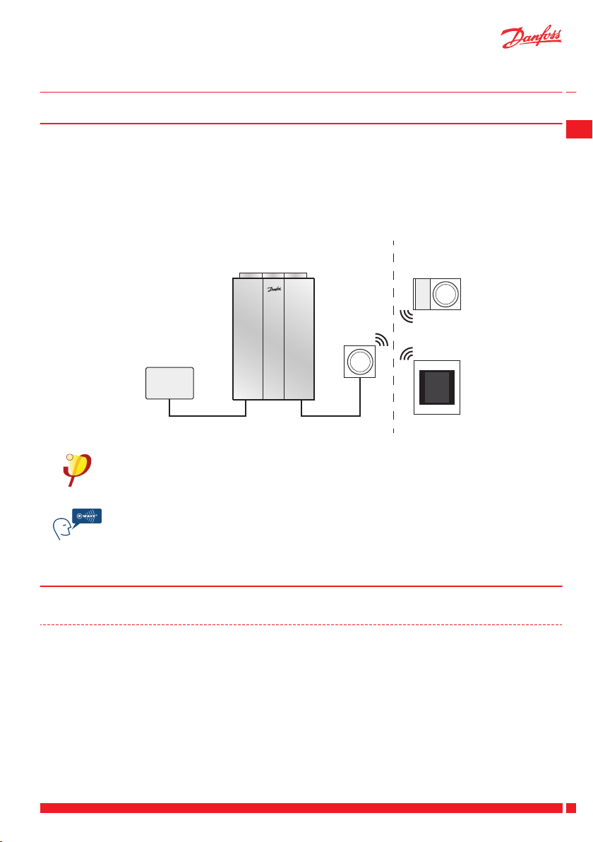
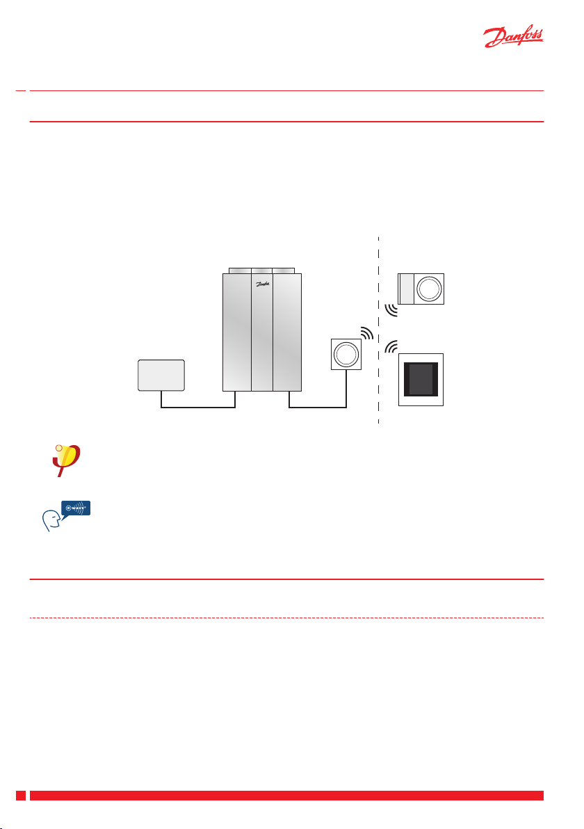
Power supply
Danfoss Air Unit
CCM
module
Air Dial
Danfoss
Link™ CC
Optional
User Guide Danfoss Air Units
2 Introduction
Congratulations on buying a Danfoss Air Unit
The Danfoss Air Units are among the most advanced, efficient, quiet and easy-to-use heat recovery ventilation
systems.
By choosing either the Air Dial or the Danfoss Link™ Central Controller, you have the entire system under control, simply by turning and pushing one dial, while all necessary information is shown in the display.
With this User Guide we wish to take you through the few steps needed to operate and to maintain your system.
All Danfoss Air units are Passive House certified by The Passive House Institute in Darmstadt.
GB
The Danfoss Air system uses Z-Wave wireless technology. Find more information on our website www.air.danfoss.com on the possibilities with Danfoss Air and Z-Wave technology.
3 Controlling the Air Unit with Air Dial
3.1 Main Menu
Main menu > Boost
The manual Boost command is used when larger air flow than normal is required, e.g. when
cooking something with a strong odour or when someone is smoking. As default the Boost
function makes the unit run at full speed for 3 hours, but these parameters can be changed in
the Settings Menu.
The Autoboost function automatically increases the air flow, if humidity suddenly increases
(e.g. caused by bathing or cooking). The Autoboost is active for 30 minutes, whereafter the
system returns to the original air flow. The Autoboost function is switched on or off in the
Settings menu.
Danfoss Heating Solutions VUEWA802
3
Page 6

User Guide Danfoss Air Units
Main menu > Away
The Away command is used to reduce the air flow to a minimum, e.g. when you leave the
house for a longer period of time. The unit will automatically return to normal operation,
when the Away period is over. Parameters for the Away period are set in the Settings menu.
Note: If a heating surface is installed, it is turned off during the Away mode (saving energy).
Main menu > Bypass (not available for w¹ units)
Bypass is a cooling function, which uses the heat exchanger for lowering the supply air tem-
perature. When the Bypass is open, outdoor air is led directly into the house.
Bypass can be activated in two ways:
1. Manually, by pressing the Bypass command. This will start the Bypass function for 3
hours (run time can be changed in the Settings menu). The Bypass will not be activated
if the outdoor temperature is below +5 °C.
2. Automatically, if both outdoor air temperature and room temperature are above the lev-
el selected in the Settings menu. The Bypass automatically closes, when one of the temperatures is below the selected level. The automatic Bypass function is switched On or
Off in the Settings menu.
Cooling Recovery function is an automatic system feature with Auto Bypass activated. If the
outdoor temperature rises above the indoor temperature, the Danfoss Air unit can automatically close the Bypass function and use the heat exchanger as a cooling application to lower
the supply temperature a few degrees. When Cooling Recovery is activated, the Bypass icon is
On.
Main menu > Info
The info command shows a list with the present status of the unit: all measured temperatures,
fan steps, relative humidity in the room and much more . . .
Main menu > Mode
With the Mode command you can choose how the Danfoss Air system is controlled:
Mode > Off
In the event of a toxic spill or fire outside the building, the unit can be turned off. After 24 hours, it starts up on step 1 of 10 to prevent moisture accumulation in the
building. Thereafter the user can change the run mode if needed.
Mode > Manual
In Manual mode the air flow is kept constantly at the selected level (fan step 1 to 10).
Bypass and Autoboost are automatically controlled, but can be switched off in the
Settings menu.
4
VUEWA802 Danfoss Heating Solutions
Page 7

%
PROG
User Guide Danfoss Air Units
Mode > Demand
In Demand mode the built-in humidity sensor ensures that the air flow is automatically regulated:
if the relative air humidity is too low inside the house, the system reduces the air
▪
flow.
if the relative air humidity is too high, the system will work with a larger air flow.
▪
Note: Outside the heating season the air flow will remain more or less constant at a rate
equivalent to the basic step settings. This ensures maximum comfort at the time of year
where heat loss is negligible.
Mode > Programme
In Programme mode one of five pre-defined family profile is chosen. Based on the
profile, ventilation rate is high during the periods when the house is occupied and
less when the house is empty. Periods of increased air flow when bathing or cooking
takes place are included in the programmes.
If none of the pre-defined profiles suits your requirements, you can download a pctool (freeware) with the option of creating your own user profile. Find the download
and installation manual at www.air.danfoss.com.
If you choose Programme mode with no further settings, thee default profile is no. 1.
GB
Danfoss Heating Solutions VUEWA802
5
Page 8
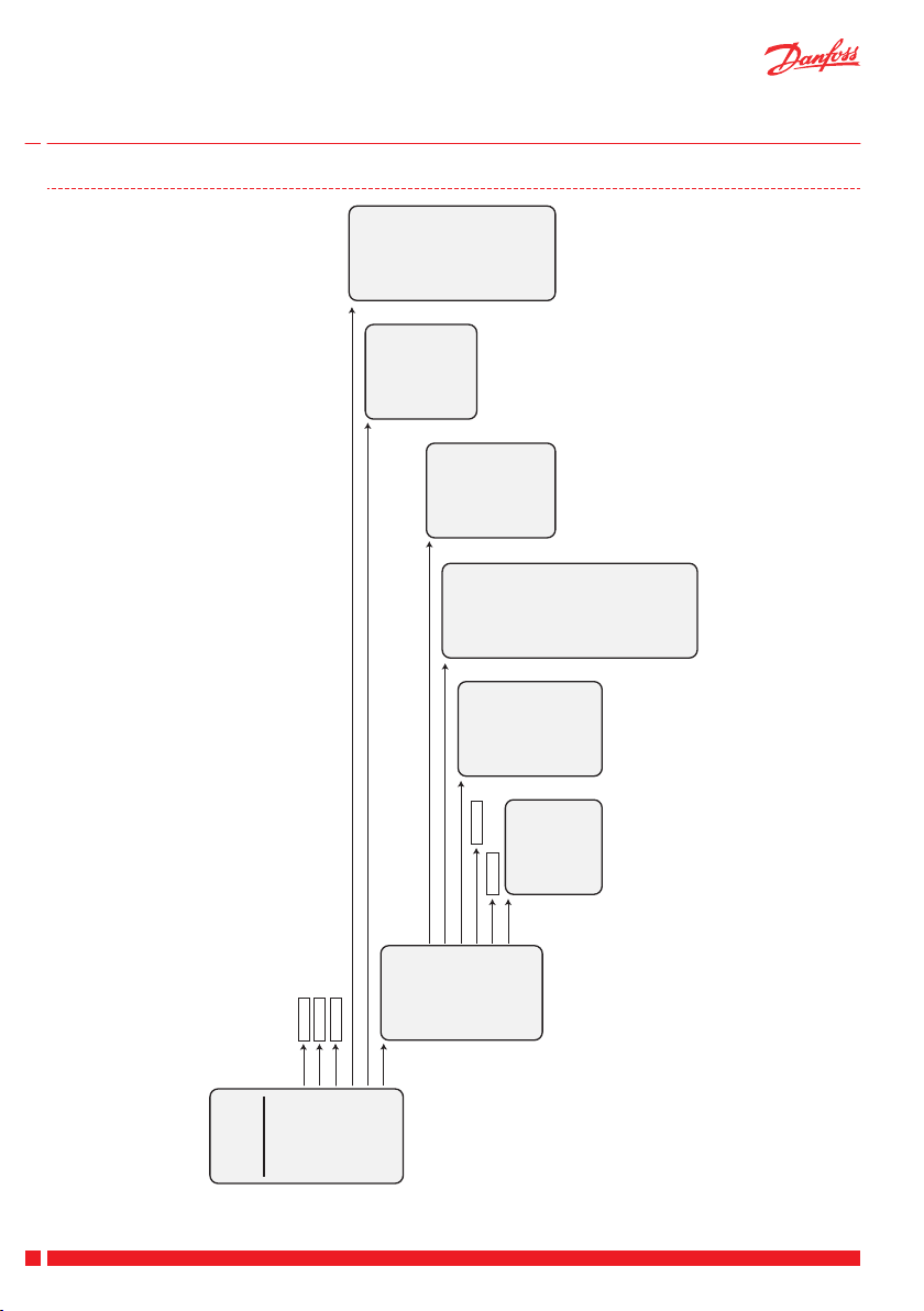
Main menu
Back
Boost
Away
Bypass
Info
Mode
Settings
On / O
Activates manual boost for a limited time
Reduces air volume to an absolute minimum inside a defined interval
Activates manual bypass for a limited time
On / O
On / O
Back
Program
Bypass
Boost
Time & Date
Night cooling
Restore defaults
Fireplace opt.
Back
Factory settings:
No
Yes
On / O
Set
Back
Boost duration:
3 hours
Auto boost:
On / O
Max. boost step:
10 / 10
Back
Bypass
(if room temp.):
>22°C
and
Outdoor air:
>16°C
Bypass duration:
3 hours
Auto bypass:
On / O
Back
Prole 1
Prole 2
Prole 3
Prole 4
Prole 5
Back
Demand
Program
Manual
O
Back
Actual step
Humidity
Filter remain
Temperatures
Accessories
Show runtime
Basic step
Alarm status
Alarm log
SW & unit ID
User Guide
3.2 Menu Structure
Danfoss Air Units
Note: The "Bypass" options and functions are not available for the "w1" unit.
6
VUEWA802 Danfoss Heating Solutions
Page 9
User Guide Danfoss Air Units
3.3 Settings
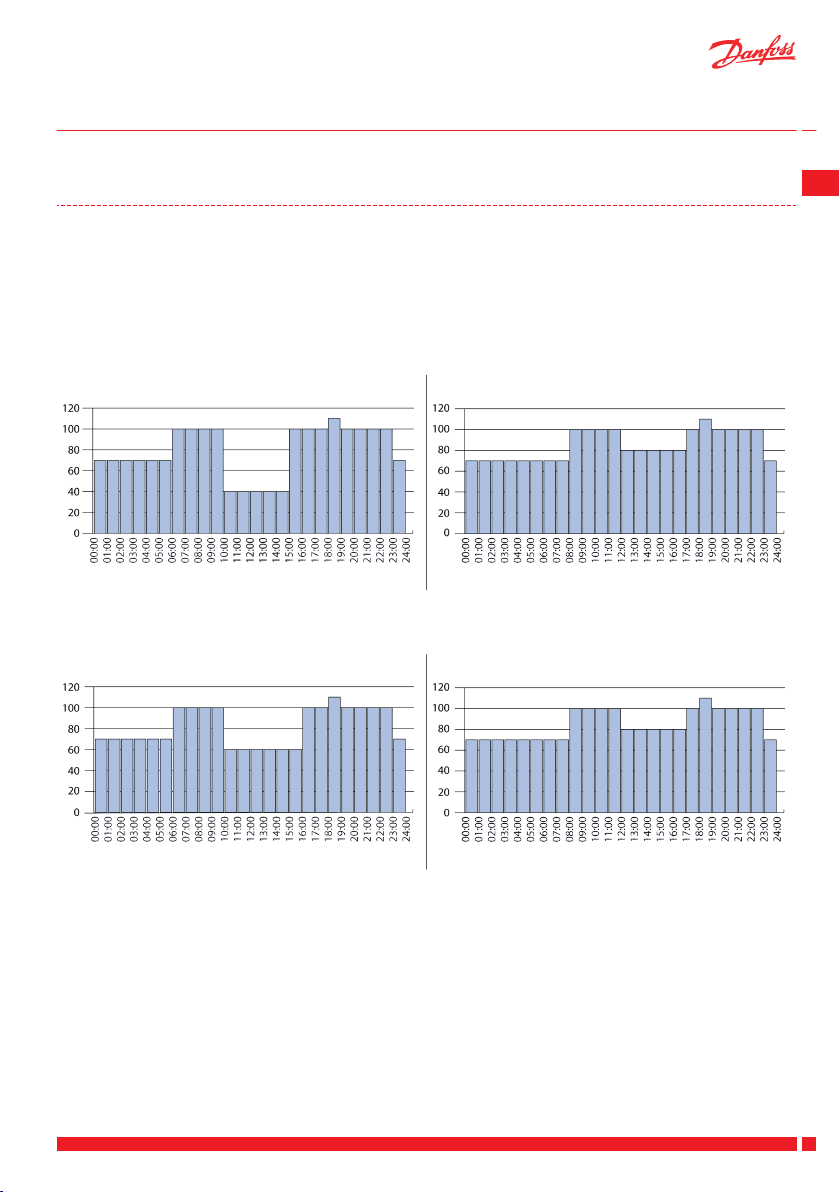
Main menu > Settings > Program > Profile 1-5
Before choosing a pre-defined program, the Program menu must be activated. Go to Main menu > Mode and
choose Program. Then you can choose between 5 different pre-programmed profiles, as shown below
Or create your own custom profile with Danfoss PC Tool, which can be downloaded from www.air.danfoss.com
(freeware). A custom profile will be visible in the menu as Main menu > Settings > Program > Profile > User
defined.
Profile 1: Family with children, both adults working normal hours.
Fan (% of basis step) Fan (% of basis step)
Weekdays Weekends
Profile 2: Family with children, one working adult, normal working hours, one adult at home during
the day.
Fan (% of basis step) Fan (% of basis step)
GB
Weekdays Weekends
Danfoss Heating Solutions VUEWA802
7
Page 10
User Guide
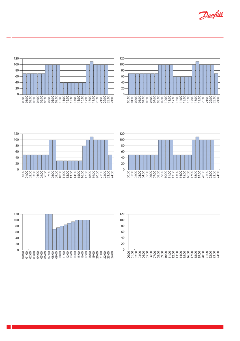
Profile 3: Couple without children, both working adults, normal working hours.
Fan (% of basis step) Fan (% of basis step)
Weekdays Weekends
Profile 4: Single person (working adult), no one at home during work hours.
Fan (% of basis step) Fan (% of basis step)
Weekdays Weekends
Danfoss Air Units
Profile 5: Small commercially used office or sales outlet area. Opening times 8 am-4 pm, closed at
weekends.
Fan (% of basis step) Fan (% of basis step)
Weekdays Weekends
Main menu > Settings > Bypass
Set parameters for the automatic Bypass (outdoor temperature and room temperature). The automatic Bypass
function is activated, when both outdoor air temperature and room temperature are above the selected parameters. If only one of the parameters is present, the automatic Bypass is not activated.
To start the Bypass manually, press the Bypass command. The Bypass is active in the time period chosen in
Main menu > Settings > Bypass > Timer (default setting is 3 hours).
The Bypass will not be activated if the outdoor temperature is below +5 °C.
Note: Bypass options and functions are not available for the "w1" unit.
8
VUEWA802 Danfoss Heating Solutions
Page 11

User Guide
Danfoss Air Units
Main menu > Settings > Boost
Customise the Boost function to match individual requirements:
Set timer for manual Boost (default is 3 hours)
▪
Turn Autoboost On or Off. When Autoboost is On, it is active in all modes.
▪
Reduce maximum Boost step, if the default maximum step (10 = 100% fan speed) is too powerful for the
▪
system.
Main menu > Settings > Time & date
Set the actual time and date of the system.
Main menu > Settings > Night cooling
Turns the Night Cooling function On or Off (default setting is Off). With Night Cooling on the system automatically detects if it was a warm day (the outdoor air temperature is over 20 °C at noon and at 4 PM) . If so, the
fresh, cool outdoor air is led directly to the supply air from midnight until 6 AM.
The Night cooling function automatically stops if the outdoor air temperature falls below 10 °C or if the extract
air temperature falls below 18 °C.
Note: Night Cooling is not available for the "w1" unit.
Main menu > Settings > Restore default
Restore all user settings to factory default values.
Main menu > Settings > Fireplace opt.
Turns the Fireplace opt. On or Off. If a fireplace is present, the Fireplace opt. can prevent the creation of unwanted negative pressure, which can cause severe problems to humans and animals. With the Fireplace opt. On the
Danfoss Air system monitors the temperature values continuously, preventing the unit from entering the automatic Defrost mode (in Defrost mode the unit de-ices the heat exchanger in periods with very low outdoor
temperatures).
If the temperature ratios demands a Defrost mode, the unit's automatic safety function immediately stops both
fans for 30 minutes, then slowly starts again and checks the temperatures. If temperatures are OK the unit returns to normal operation, if temperatures are not OK the unit re-enters the safety function and stops for an
additional 30 minutes.
To avoid problems with negative pressure Danfoss recommends to install a pre-heating surface with the Danfoss Air unit (see Heating Surfaces).
GB
Adjustment of the Danfoss Air unit
When you are going to commission your unit for the first time or if you want to install a fireplace after some
time, we recommend you to adjust both supply and extract air to be equal. Hereby you secure a "balanced"
airflow.
A too large supply air rate can cause an overpressure in the building. This must be avoided at any means due to
an unwanted accumulation of humidity in the building.
Important!
A big cooker hood with direct exhaust, can challenge the Air Unit during the winter period.
If you experience that the air flow is cold, the reason might be that the cooker hood engine is stronger than the
Air Unit engine. The Air Unit experiences a negative pressure and compensates through supply and extract.
Low outdoor temperatures affect the heat exchanger and when the temperature sensor detects that, the Defrost mode is activated.
Danfoss Heating Solutions VUEWA802
9
Page 12
2
1
Danfoss
One®
User Guide Danfoss Air Units
If the temperature ratios demands a Defrost mode, the unit's automatic safety function might stop both fans
for 30 minutes, then slowly starts again and check the temperatures. If the temperatures are OK, the unit returns to normal operation. If the temperatures are not OK, the unit re-enters the safety function and stops for
additional 30 minutes.
To avoid problems with negative pressure Danfoss recommends to:
1. Install a damper in the kitchen.
2. Open a window when using the cooker hood.
Note: If you experience any problems with negative pressure, contact your installer and ask if a damper is installed.
Negative pressure is often a challenge in new-build and energy renovated houses.
Legislative conditions
The installation of a Danfoss Air system must always comply with all national, regional or local legislations and
rules.
3.4 Replacing Air Dial Batteries
When the Air Dial needs a new set of batteries it is indicated by an alarm
sound.
Lift the Air Dial off the wall bracket and replace with four AAA batteries.
4 Controlling the Air Unit with Danfoss Link™ Central Controller
If you control the air unit with Danfoss Link™ CC, you can find general
information and instructions for air units in a Danfoss One® system, by
compiling a user guide at www.link.danfoss.com.
10
VUEWA802 Danfoss Heating Solutions
Page 13
User Guide Danfoss Air Units
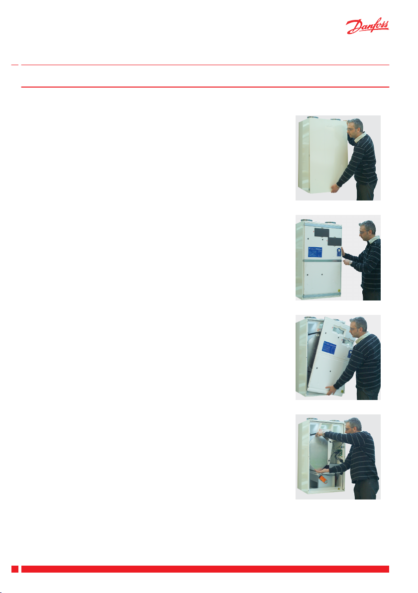
5 Replacing Filters
Danfoss Air units are designed for an absolute minimum of maintenance. Maintenance is limited to one or two
filter replacements a year, depending on air volume and local air pollution level.
In industrial areas and in areas with a high concentration of pollen in the outdoor air the filters will be clogged
faster than in a typical suburban environment.
Danfoss Air units are fitted with original filters that are designed to protect the unit and the indoor climate.
These filters have been tested and validated, so that they also protect the internal components like heat exchanger and fans. If other filters than the original spare parts are used, Danfoss cannot guarantee the full quality or lifetime for the internal components.
Standard filters and optional pollen filters (F7 class) can be purchased from your installer.
Replace filters when Air Dial gives the filter alarm (alarm sound from and message in display):
1. Remove the front panel (no tools needed).
2. Pull out the filters and inspect them visually.
3. If the filter is only lightly fouled/discoloured, you might try to clean it, using a vacuum cleaner with a
brush. Normally this will not be worthwhile nor recommended.
4. Fit new filters* and reattach the foam covers.
5. Press the filter reset button on the front of the unit.
* If you have bought a special pollen filter, it should be fitted in the filter slot to the right (on all models), as this is
filtering the outdoor air.
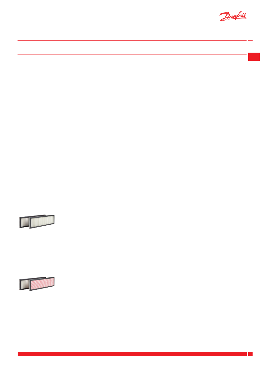
Standard filter set
The standard filter set are G4 class for both supply and discharge air, which provide basic filtration of particles
larger than 10 μm.
Order no.
G4/G4 standard filter set for Danfoss Air Unit w¹ 089F0238
G4/G4 standard filter set for Danfoss Air Unit w² 089F0239
G4/G4 standard filter set for Danfoss Air Unit a² 089F0236
G4/G4 standard filter set for Danfoss Air Unit a³ 089F0237
GB
Pollen filter set
If allergies are present in your family, choose a pollen filter set with F7 class filter for supply air to effectively
filter out pollen.
Order no.
G4/F7 pollen filter set for Danfoss Air Unit w¹ 089F0242
G4/F7 pollen filter set for Danfoss Air Unit w² 089F0243
G4/F7 pollen filter set for Danfoss Air Unit a² 089F0240
G4/F7 pollen filter set for Danfoss Air Unit a³ 089F0241
Danfoss Heating Solutions VUEWA802
11
Page 14
User Guide Danfoss Air Units
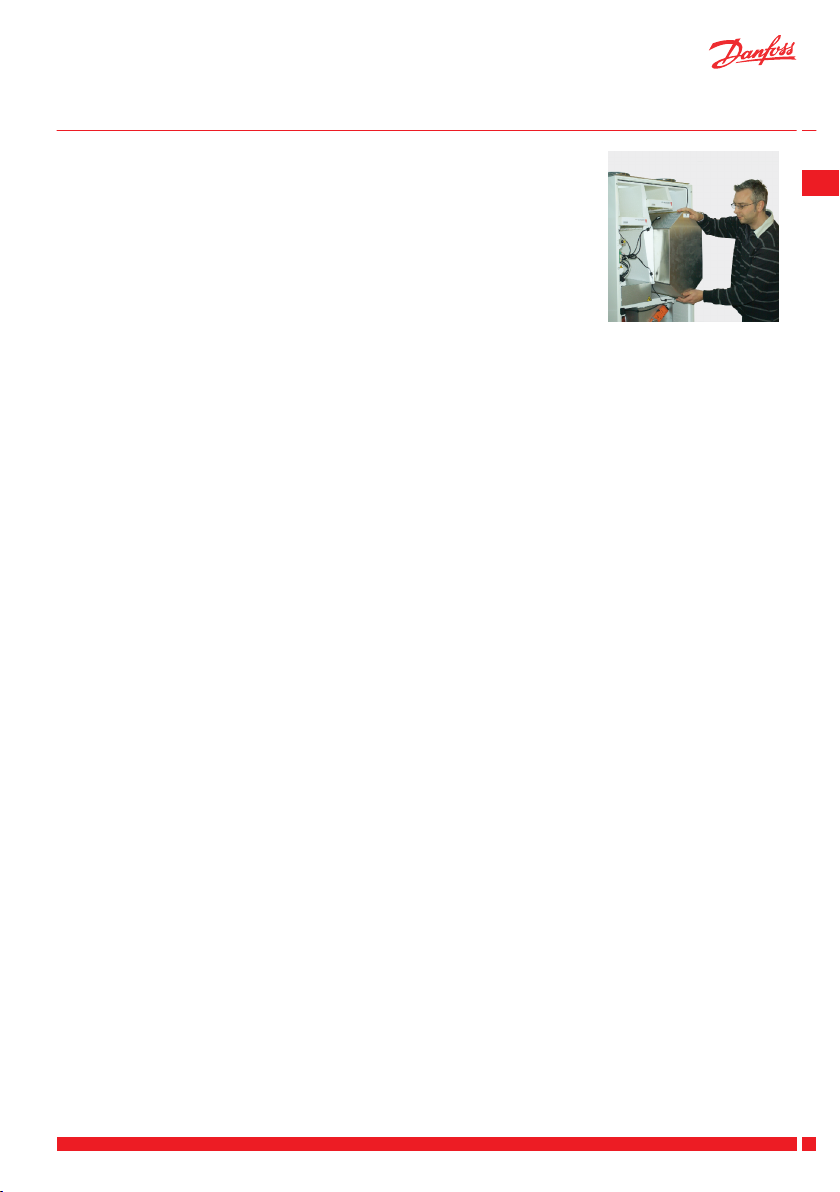
6 Cleaning the Air Unit
The inside of the Danfoss air unit should be cleaned every other year.
1. Disconnect power and remove the front panel.
2. Remove the six screws holding the three metal rails (using the correct
size torx key).
3. Remove the front foam panel to get access to the parts inside the unit.
4. Pull the thick round seal over the heat exchanger out sideways. When
remounting the exchanger, the round seal should be inserted last. This
is best done by ‘locking in the two ends’ first and then pushing the rest
of the seal into place.
12
VUEWA802 Danfoss Heating Solutions
Page 15
User Guide
Danfoss Air Units
5. The heat exchanger can now be lifted/pulled carefully out of the core.
6. Pour a mild solution of regular dishwashing soap through the four open sides of the heat exchanger.
Let it soak for 5-10 minutes before rinsing under running water. Dry the exterior of the heat exchanger,
and gently slide the heat exchanger back into the unit.
Clean interior surfaces of the unit with a wet sponge or cloth (use a mild soapy solution).
Under no circumstances use solvents for cleaning the foam parts, as solvents can dissolve the special
foam material.
Avoid spraying water onto the main circuit board. If water is spilled onto the board, tap it lightly with a
dry cloth and leave to air dry for min. 24 hours before reconnecting the power.
Assemble the unit in reverse order:
1. Install the foam front panel.
2. secure the panel with the three metal rails.
3. Tighten torx screws.
4. Reinstall the front panel.
GB
You are now ready for another two years of trouble-free operation.
Danfoss Heating Solutions VUEWA802
13
Page 16
3
4
1
2
+
3
4
1
2
+
User Guide Danfoss Air Units
7 Heating Surfaces
A pre-heating surface gives a large range of benefits for the Danfoss Air system and the indoor climate in general. Danfoss always recommends to install a pre-heating surface with the Danfoss Air unit.
With a pre-heating surface the system is protected against entering the automatic Defrost mode, which can
cause negative pressure in the building - especially if a fireplace is present.
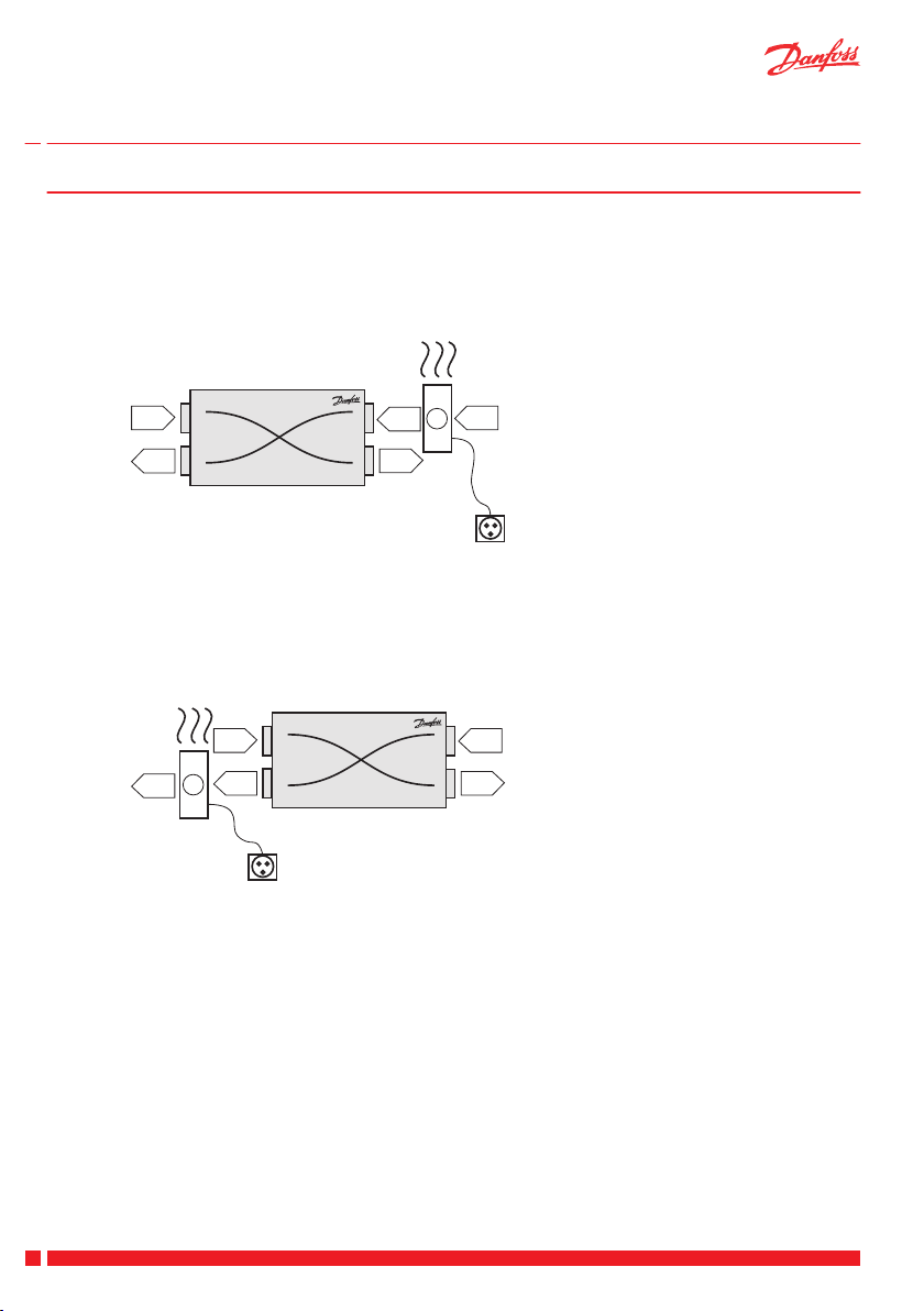
Preheating surface, electric
1. Outdoor air
2. Supply
3. Extract
4. Exhaust
The electric preheating surface is used to protect the system against icing up at low outdoor temperatures.
Before the outside air reaches the system, it is heated up from the current outside temperature to 0°C (which
makes frost formation in the exchanger impossible). This solution ensures a permanent balance between the
supply and extraction air. Adjustment is 100% stepless to ensure the lowest possible power consumption
during operation. No settings are required on an electric preheating surface.
Afterheating surface, electric
1. Outdoor air
2. Supply
3. Extract
4. Exhaust
The electric afterheating surface is used to ensure a minimum supply temperature before the air is blown into
the room. The ventilation system will usually heat the outside air up to a temperature that is very close to
room temperature so the electric afterheating surface is only used to give the supply temperature a little lift.
Adjustment is 100% stepless to ensure the lowest possible power consumption during operation.
The required supply temperature can be set from the Air Dial in Main menu > Settings > Temperature > Sup-
ply.
14
VUEWA802 Danfoss Heating Solutions
Page 17
4
1
5
3
2
+
6
3
2
4
1
User Guide Danfoss Air Units
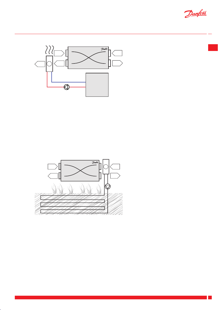
Afterheating surface, water-based
1. Outdoor air
2. Supply
3. Extract
4. Exhaust
5. Pump
6. Central heating
The water-based afterheating surface is (most often) used to ensure a minimum supply temperature before
the air is blown into the room. The ventilation system will usually heat the outdoor air up to a temperature
that is close to room temperature so the water-based afterheating surface is only used to give the supply
temperature a little lift.
100% stepless control is carried out via the built-in motor valve.
The required supply temperature can be set from the Air Dial in Main menu > Settings > Temperature > Sup-
ply.
The afterheating surface can also in special cases be used as total heating in passive or 0 energy houses if all
parts of the system have been dimensioned for it. If your system was configured for air heating, the room
temperature can be set in the main menu.
Preheating/cooling surface, geothermal
GB
1. Outdoor air
2. Supply
3. Extract
4. Exhaust
5. Pump
The geothermal surface is able either to preheat or precool the outside air depending on the season. The control automatically determines what is required and controls the surface in and out of operation as required.
The geothermal surface is provided with ‘anti-freeze’ (brine) which is circulated in a buried ground pipe using
a circulation pump. This means that it is ‘free renewable energy’ that can be used with a clean conscience.
In the winter, preheat can be used to prevent the system from going into frost protection mode and in the
summer it can provide pleasant additional cooling by cooling the air before it reaches the system. When the
geothermal surface is cooling, the ventilation system’s bypass of course opens automatically.
Danfoss Heating Solutions VUEWA802
15
Page 18
User Guide Danfoss Air Units
8 PC Controls
Control your DANFOSS AIR system from your PC screen via Ethernet.
Make customised weekly programmes with the user-friendly week programme editor.
▪
Monitors and displays all temperatures and relative humidity in the house, in a single screenshot
▪
See trend curves for the last 14 days, all relevant sensors are logged hourly
▪
Easy access to advanced settings, all functions are described in a short and easy to understand text.
▪
Download Danfoss Air PC Tool from www.air.danfoss.com - it is free of charge!
Note: There are limited options in the Danfoss Air PC
Tool, when using Danfoss Link™ CC.
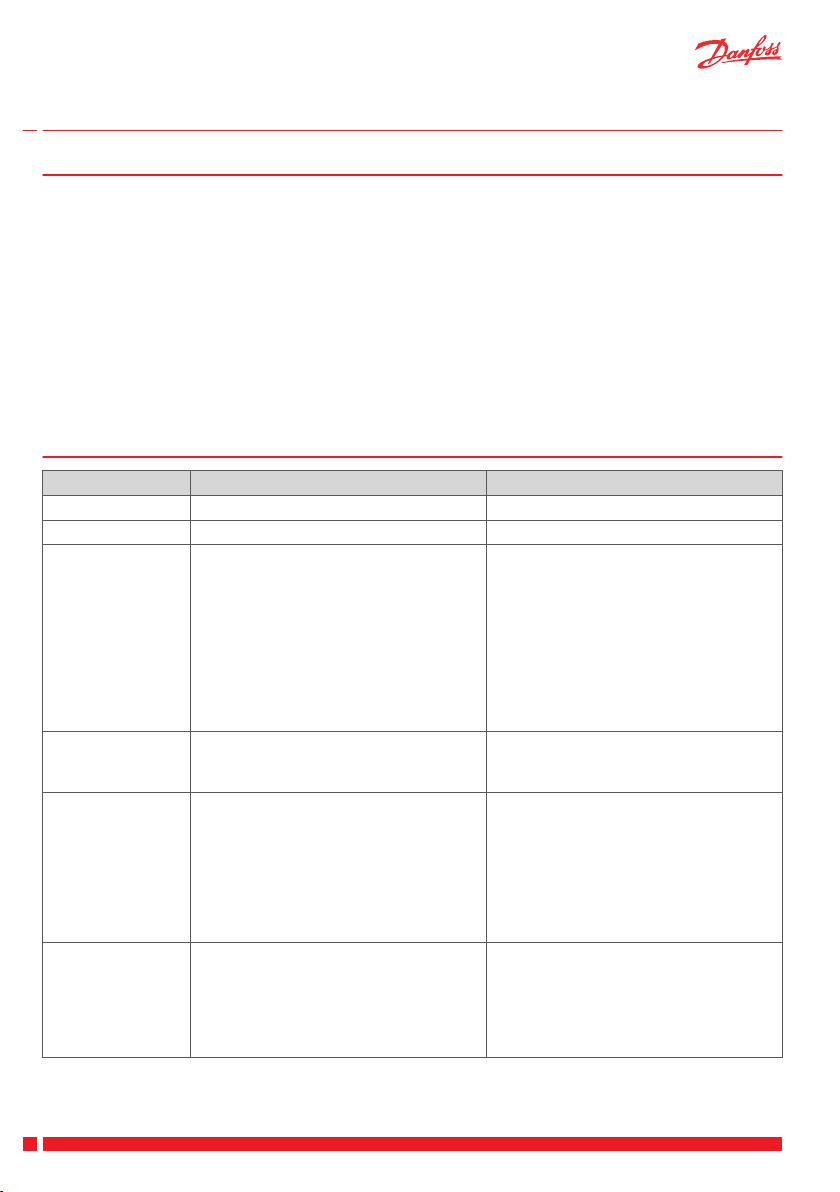
9 Troubleshooting
Error Cause Solution
Alarm:Filter error Air filters are dirty. Exchange air filters.
Alarm: Battery low Battery voltage in Air Dial is too low. Replace batteries (4 x AAA) in Air Dial.
Alarm: No connec-
tion to CCM
Alarm: No connection via modbus
Alarm: Room air
too cold
Alarm: Fire One of four temperature sensors in Dan-
Communication between Air Dial and
CCM module has failed, typically caused
by an obstacle between Air Dial and CCM
module, e.g. steel piping, other steel objects, insulation material clad with aluminum foil, etc. Another cause can be other
wireless appliances that does not conform
to wireless standards (radio noise).
Cable between CCM module and unit is
unplugged or defective.
Central heating system is not supplying
heat. Room temperature is dropping, so
the unit turn off to reduce involuntary
heat loss. Alarm active if Air Dial measures
a room temperature below +10°C.
foss Air unit or temperature sensor in Air
Dial remote control has detected a temperature higher than +70°C. Unit turns off
until all sensors indicate < +70°C.
If an obstacle has been identified, move it.
If this is not possible, move CCM module
to a better location with a free ‘line of
sight’.
If the error occurs due to other wireless
appliances in your house, try switching
these off in turn to identify the faulty device.
If none of the above helps, please contact
your installer.
Check cable and reconnect if necessary. If
cable is connected, but error still occurs contact installer.
Check if heating system is functional. If the
problem can not be solved, contact
plumber/installer.
When error has been remedied, shut
down and restart ventilation system to resume normal operation. Power can be disconnected by pulling power cable from
system.
Examine all rooms, leave the house.
When error has been remedied, shut
down and restart ventilation system to resume normal operation. Power can be disconnected by pulling power cable from
system.
16
VUEWA802 Danfoss Heating Solutions
Page 19
User Guide Danfoss Air Units
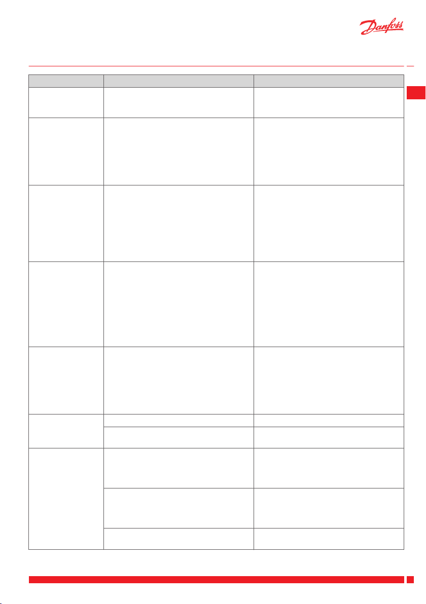
Error Cause Solution
Alarm: Sensor error Temperature sensor in Danfoss Air unit or
Air Dial is defective.
Alarm: Supply air
too cold
The supply air sensor has detected a supply temperature below +5°C and the unit
automatically stops to prevent unwanted
cooling of the building. This detection is
caused by negative pressure due to an external influence, e.g. a cooker hood with
direct exhaust.
Alarm: Fireplace
stop activated
With Fireplace opt. activated: the unit has
stopped due to a risk of a negative pressure.
Abnormally large
negative pressure
inside the house,
doors binding
Discharge air flow is larger than supply air
flow. Either balancing was not carried out
correctly during set-up of the system or
unit is in extreme defrost conditions (can
occur at outdoor temperatures < -12°C).
Condensation in
window frames
Air exchange is too low. Condensation occurs when humidity is high and surface
temperatures are low, typically in bathrooms or utility rooms, where clothes are
drip drying (some condensation in bathrooms following a shower is normal, but
should disappear within half an hour).
House temperatures are too high
House thermostats are set too high. Turn down thermostats.
Bypass is disabled on ventilation system. Enable Bypass in Main menu > Bypass >
Noise from unit a-type unit: vibration noise may occur if
unit is mounted directly onto joists. Unit
should be mounted on a suitable platform.
w-type unit: vibration noise may occur if
rubber spacers are not fitted between unit
and wall and/or if silicone strip is not fitted
onto wall bracket.
Defective fan bearings will produce a
‘grinding noise’.
Contact installer.
System continues to run, but with limited
functionality.
Power cycle the unit to start it again. Investigate which household appliance is
the cause of the alarm. Danfoss recommends installing a pre-heating surface
or/and using household components with
air recirculation. For further details contact
your installer.
The unit stops for 30 minutes, then all
temperatures are checked. If temperatures
are OK the units starts again. If not the unit
will cycle this process continuously until
all temperatures are in the right range.
A permanent solution could be installing a
pre-heating surface. Contact your installer
for further details.
Imbalance of flow should be 4-10% in favour of discharge air, but if problems with
doors binding is permanent, contact installer.
If problems only arises during extreme
winter condition, it is due to the integrated defrost controller that reduces the
supply air (hence not a defect, but an expected, and very rare occurrence).
Increase fan step (Manual mode) or
change to Demand mode or Programme
mode.
Set Autoboost On.
Auto bypass.
Check that unit is mounted on platform,
according to installation manual.
Check that rubber spacers and silicone
strip are fitted, according to installation
manual.
If fan ball bearing is suspected to be defective, contact installer.
GB
Danfoss Heating Solutions VUEWA802
17
Page 20
User Guide Danfoss Air Units
Error Cause Solution
Noise from Air
valves
Frost icon in display The system is in defrost mode, because
Air flow is too high. Noise is not a problem in a correctly sized
Pressure is too high over valve.
No silencer is fitted to main duct.
and commissioned system. However, if air
valves are closed (e.g. during cleaning), a
hissing noise may occur.
This is not an error, but a standard mode.
low outdoor temperatures entail a risk of
ice forming in the heat exchanger.
The function stops automatically when
the outdoor temperature rises.
18
VUEWA802 Danfoss Heating Solutions
Page 21

Brugervejledning
Indholdsfortegnelse
Danfoss Air ventilationsanlæg
1 Sikkerhedsnoter .......................................... 19
2 Introduktion ............................................. 20
3 Styring af Air ventilationsanlægget ved hjælp af Air Dial .................. 20
3.1 Hovedmenu .......................................... 20
3.2 Menustruktur ......................................... 23
3.3 Indstillinger .......................................... 24
3.4 Udskiftning af Air Dial-batterier ............................... 27
4 Styring af Air ventilationsanlægget med Danfoss Link™ Central styring ......... 27
5 Udskiftning af filtre ......................................... 28
6 Rengøring af ventilationsanlægget ............................... 29
7 Varmeflader ............................................. 31
8 PC-styring .............................................. 33
9 Fejlfinding .............................................. 33
1 Sikkerhedsnoter
Dette apparat er ikke beregnet til at blive brugt af personer (herunder børn) med nedsat fysisk, sansemæssig
eller psykisk formåen eller med manglende erfaring og viden, medmindre de er under opsyn eller er blevet
instrueret i brugen af apparatet af en person, der er ansvarlig for deres sikkerhed.
Børn skal være under opsyn for at sikre, at de ikke leger med apparatet.
Ud over at skifte luftfilter og rengøre anlægget udvendigt, vil enhver form for service kræve uddannet personale.
DK
Danfoss Heating Solutions VUEWA801
19
Page 22
Strømforsyning
Danfoss Air ventilationsanlæg
Air Dial
Valgfrit
CCMmodul
Danfoss
Link™ CC
Brugervejledning Danfoss Air ventilationsanlæg
2 Introduktion
Tillykke med købet af et Danfoss Air ventilationsanlæg.
Danfoss Air ventilationsanlæg er et af de mest avancerede, effektive, støjsvage og brugervenlige ventilationssystemer med varmegenindvinding, der findes.
Du styrer hele systemet ved hjælp af enten din Air Dial eller Danfoss Link™ Central styring. Du skal blot dreje og
trykke på skiven, så vises alle de nødvendige oplysninger på displayet.
I denne brugervejledning vil vi gerne vise dig de få trin, der er nødvendige, for at du kan betjene og vedligeholde dit system.
Alle Danfoss Air ventilationsanlæg er certificeret til brug i passivhuse af Passivhaus Institut i
Darmstadt.
Danfoss Air systemet benytter den trådløse teknologi Z-Wave. Du kan finde flere oplysninger
om de mange muligheder, der findes med Danfoss Air og Z-Wave teknologien, på vores
hjemmeside varme.danfoss.dk.
3 Styring af Air ventilationsanlægget ved hjælp af Air Dial
3.1 Hovedmenu
Hovedmenu > Boost
Den manuelle Boost-funktion kan anvendes i situationer, hvor der kræves en større luftstrøm-
ning end normalt, fx hvis du laver mad, der lugter stærkt, eller hvis nogen ryger. Som standard får Boost-funktionen anlægget til at køre på fuld hastighed i tre timer, men disse parametre kan ændres i menuen Indstillinger.
Autoboost-funktionen øger automatisk luftstrømningen, hvis den relative luftfugtighed i boligen pludselig øges (fx på grund af madlavning, eller hvis nogen tager bad). Autoboost er
aktiv i 30 minutter, hvorefter systemet vender tilbage til den oprindelige luftstrømning. Autoboost-funktionen slås til eller fra via menuen Indstillinger.
20
VUEWA801 Danfoss Heating Solutions
Page 23
Brugervejledning Danfoss Air ventilationsanlæg
Hovedmenu > Bortrejst
Bortrejst-funktionen bruges til at reducere luftstrømningen til et minimum, fx når du forlader
huset i en længere periode. Anlægget genoptager automatisk normal drift, når Bortrejst-perioden er slut. Parametrene for Bortrejst-perioden indstilles via menuen Indstillinger.
Bemærk: Hvis der er installeret en varmeflade, slukkes den i Bortrejst-perioden (for at spare på
energien).
Hovedmenu > Bypass (ikke tilgængelige på w¹-anlæg)
Bypass-funktionen er en passiv kølingsfunktion. Når der er åbent for bypass, ledes udeluften
uden om varmeveksleren i ventilationsanlægget og tilføres boligen uopvarmet.
Bypass kan aktiveres på to måder:
1. Manuelt ved at trykke på kommandoen Bypass. Det får Bypass-funktionen til at køre i tre
timer (driftstiden kan ændres i menuen Indstillinger). Bypass vil ikke blive aktiveret, hvis
udetemperaturen er under +5 °C.
2. Automatisk, hvis både udetemperaturen og rumtemperaturen ligger over det niveau,
der er valgt i menuen Indstillinger. Bypass lukker automatisk, når en af temperaturerne
er lavere end det valgte niveau. Den automatiske Bypass-funktion slås til eller fra via
menuen Indstillinger.
Funktionen Kølegenindvinding er en automatisk systemfunktion, når Automatisk bypass er
aktiveret. Hvis udetemperaturen stiger til over indetemperaturen, kan Danfoss Air ventilationsanlægget automatisk lukke Bypass-funktionen og bruge varmeveksleren som afkølingsapparat, så indblæsningstemperaturen sænkes et par grader. Når kølegenindvinding er aktiveret, er ikonet Bypass tændt.
DK
Hovedmenu > Info
Menuen Info viser en liste over anlæggets aktuelle status: alle målte temperaturer, ventilatortrin, relativ luftfugtighed i rummet og meget mere.
Hovedmenu > Driftsform
Ved hjælp af menuen Driftsform kan du vælge, hvordan Danfoss Air systemet styres:
Tilstand > Fra
I tilfælde af giftudslip eller brand uden for bygningen kan anlægget deaktiveres. Efter
24 timer starter det igen på trin 1 af 10 for at forhindre fugtdannelse i bygningen. Brugeren kan derefter ændre driftstilstand efter behov.
Tilstand > Manuel
I tilstanden Manuel holdes luftstrømningen konstant på det valgte niveau (ventilatortrin 1 til 10). Bypass og Autoboost styres automatisk, men de kan slås fra via menuen
Indstillinger.
Danfoss Heating Solutions VUEWA801
21
Page 24

%
PROG
Brugervejledning Danfoss Air ventilationsanlæg
Tilstand > Behov
I tilstanden Behov sikrer den indbyggede fugtføler, at luftstrømningen reguleres
automatisk:
Hvis den relative luftfugtighed er for lav inde i huset, sænker systemet luft-
▪
strømningen.
Hvis den relative luftfugtighed er for høj, arbejder systemet med en større luft-
▪
strømning.
Danfoss anbefaler som udgangspunkt behovsstyring, der automatisk tilpasser luftstrømningen til boligen, hvilket giver højest mulige komfortniveau, ved lavest mulige
energiforbrug og varmetab.
Bemærk: Uden for opvarmningssæsonen forbliver luftstrømningen mere eller mindre konstant på et niveau, der svarer til indstillingerne for grundtrinene. Det sikrer maksimal komfort på de tidspunkter på året, hvor varmetabet er ubetydeligt.
Driftsform > Ugeprogram
I driftsformen Ugeprogram vælges en af fem foruddefinerede familieprofiler. Afhængigt af profilen er ventilationsraten høj i de perioder, hvor der er nogen hjemme, og
lavere, når huset er tomt. Der er indlagt perioder med en højere luftstrømning i programmet, til brug når der fx laves mad eller tages bad.
Hvis ingen af de foruddefinerede profiler passer til dine behov, kan du downloade et
PC-værktøj (freeware), der giver dig mulighed for at oprette din egen brugerprofil. Du
downloader programmet og installationsmanualen på varme.danfoss.dk.
Hvis du vælger driftsformen Ugeprogram uden yderligere indstillinger, er standardprofilen nr. 1.
22
VUEWA801 Danfoss Heating Solutions
Page 25

Hovedmenu
Tilbage
Boost
Bortrejst
Bypass
Info
Driftsform
Indstillinger
Fra / Til
Aktiverer manuel boost i tidsbegrænset periode
Reducerer luftskifte til absolut minimum i ferieperioder
Aktiverer manuel bypass i tidsbegrænset periode
Fra / Til
Fra / Til
Tilbage
Ugeprogram
Bypass
Boost
Tid & Dato
Natkøling
Gendan
Tilbage
Fabriks-
indstillinger:
Nej
Ja
Fra / Til
Indstil
Tilbage
Boost timer:
3 timer
Auto boost:
Til / Fra
Max. boost trin:
10 / 10
Tilbage
Bypass hvis
rumtemperatur:
>22°C
og
Udetemperatur:
>16°C
Bypass timer:
3 timer
Auto bypass:
Til / Fra
Tilbage
Profil 1
Profil 2
Profil 3
Profil 4
Profil 5
Tilbage
Behov
Ugeprogram
Manuel
Fra
Tilbage
Vis trin
Rel. fugt %
Luftfilter
Temperaturer
Tilbehør
Driftstid
Basis trin
Alarmstatus
Alarm liste
SW & Model
Brugervejledning
3.2 Menustruktur
Danfoss Air ventilationsanlæg
DK
Bemærk: Muligheder og funktioner for "Bypass" er ikke tilgængelige på "w1"-anlægget.
Danfoss Heating Solutions VUEWA801
23
Page 26

Brugervejledning Danfoss Air ventilationsanlæg
3.3 Indstillinger
Hovedmenu > Indstillinger > Ugeprogram > Profil 1-5
Før du vælger et foruddefineret ugeprogram, skal du aktivere menuen Ugeprogram. Gå til Hovedmenu >
Driftsform, og vælg Ugeprogram. Her kan du vælge mellem fem forskellige foruddefinerede profiler som vist
nedenfor.
Du kan også oprette din egen tilpassede profil ved hjælp af programmet Danfoss Air PC Tool, som du kan
downloade på varme.danfoss.dk (freeware). Din tilpassede profil vil kunne ses i menuen under Hovedmenu >
Indstillinger > Ugeprogram > Profil > Brugerdefineret.
Profil 1: Familie med børn, begge voksne har normale arbejdstider uden for hjemmet.
Ventilator (% af grundtrin) Ventilator (% af grundtrin)
Hverdage Weekender
Profil 2: Familie med børn, én voksen har normale arbejdstider uden for hjemmet, én voksen er hjemme om dagen.
Ventilator (% af grundtrin) Ventilator (% af grundtrin)
Hverdage Weekender
24
VUEWA801 Danfoss Heating Solutions
Page 27

Brugervejledning
Danfoss Air ventilationsanlæg
Profil 3: Par uden børn, begge voksne har normale arbejdstider uden for hjemmet.
Ventilator (% af grundtrin) Ventilator (% af grundtrin)
Hverdage Weekender
Profil 4: Enlig uden børn, én voksen med normale arbejdstider uden for hjemmet.
Ventilator (% af grundtrin) Ventilator (% af grundtrin)
Hverdage Weekender
DK
Profil 5: Lille kommercielt anvendt kontor eller salgslokale. Åbningstider 8:00 til 16:00, lukket i weekenden.
Ventilator (% af grundtrin) Ventilator (% af grundtrin)
Hverdage Weekender
Hovedmenu > Indstillinger > Bypass
Parameterangivelser for den automatiske Bypass-funktion (udetemperatur og rumtemperatur). Den automatiske Bypass-funktion aktiveres, når både udetemperatur og rumtemperatur ligger over de valgte parametre.
Hvis kun en af parametrene er til stede, aktiveres det automatiske bypass ikke.
Tryk på kommandoen Bypass for at starte bypass manuelt. Bypass er aktiv i den periode, der er valgt under
Hovedmenu > Indstillinger > Bypass > Timer (standardindstillingen er tre timer).
Bypass vil ikke blive aktiveret, hvis udetemperaturen er under +5 °C.
Bemærk: Muligheder og funktioner for Bypass er ikke tilgængelige på "w1"-anlægget.
Danfoss Heating Solutions VUEWA801
25
Page 28

Brugervejledning
Hovedmenu > Indstillinger > Boost
Du kan tilpasse funktionen Boost, så den matcher individuelle behov:
Indstil timeren for manuel boost (standarden er tre timer)
▪
Slå Autoboost til eller fra. Når Autoboost er slået til, er den aktiv i alle driftsformer.
▪
Reducér maksimum boosttrin, hvis standarden for maksimumtrin (10 = 100 % ventilatorhastighed) er for
▪
kraftig for systemet.
Hovedmenu > Indstillinger > Tid & dato
Angiv faktisk tidspunkt og dato for systemet.
Hovedmenu > Indstillinger > Natkøling
Slår funktionen Natkøling til eller fra (standardindstilling er Fra). Når natkølingen er slået til, registrerer systemet
automatisk, om det var en varm dag (udetemperaturen er over 20 °C klokken 12:00 og klokken 16:00). I så fald
føres den friske, kølige udeluft direkte til indblæsningen fra midnat til klokken 6:00.
Funktionen Natkøling stopper automatisk, hvis udetemperaturen falder til under 10 °C, eller hvis udsugningslufttemperaturen falder til under 18 °C.
Bemærk: Natkøling er ikke tilgængelig på "w1"-anlægget.
Hovedmenu > Indstillinger > Gendan
Gendan alle brugerindstillinger til fabriksstandardværdier.
Vigtigt!
En stor emhætte med direkte afkast kan skabe udfordringer for Air ventilationsanlægget i vinterperioden.
Hvis du oplever, at luftstrømningen er kold, kan årsagen være, at emhættens motor er stærkere end Air ventilationsanlæggets motor. Danfoss Air ventilationsanlægget oplever et undertryk, der kompenseres gennem indblæsning og udsugning.
Danfoss Air ventilationsanlæg
Lav udetemperatur påvirker varmeveksleren, og når temperaturføleren registrerer dette, aktiveres afisningstilstand. NB: I ekstreme tilfælde vil ventilationsanlægget aktivere et fuldt drifststop, som kræver manuel genstart
af ventilationsanlægget.
Hvis temperaturforholdene kræver en afisningstilstand, kan ventilationsanlæggets automatiske sikkerhedsfunktion standse begge blæsere i 30 minutter, og derefter langsomt starte igen og kontrollere temperaturerne.
Hvis temperaturerne er OK, vender ventilationsanlægget tilbage til normal drift. Hvis temperaturerne ikke er
OK, genoptager ventilationsanlægget sikkerhedsfunktionen og standser i yderligere 30 minutter.
For at undgå problemer med undertryk anbefaler Danfoss at:
1. Installere et erstatningsluftspjæld i køkkenet.
2. Åbne et vindue ved anvendelse af emhætte.
Bemærk: Hvis du oplever problemer med undertryk, kan du kontakte din installatør og spørge, hvorvidt der er installeret et spjæld.
Undertryk er ofte en udfordring i nybyggeri og energirenoverede huse.
Installation af et Danfoss Air System skal altid overholde alle nationale, regionale eller lokale love og regler.
26
VUEWA801 Danfoss Heating Solutions
Page 29

2
1
Danfoss
One®
Brugervejledning Danfoss Air ventilationsanlæg
3.4 Udskiftning af Air Dial-batterier
Når Air Dial har brug for et nyt sæt batterier, angives det ved hjælp af en
alarmlyd.
Løft Air Dial af vægbeslaget, og udskift med fire nye AAA-batterier.
4 Styring af Air ventilationsanlægget med Danfoss Link™ Central styring
Hvis du styrer Air ventilationsanlægget med Danfoss Link™ CC, kan du
finde generelle oplysninger og vejledning til Air ventilationsanlæg i et
Danfoss One®-system ved at hente en brugervejledning på
www.link.danfoss.com.
DK
Danfoss Heating Solutions VUEWA801
27
Page 30

Brugervejledning Danfoss Air ventilationsanlæg
5 Udskiftning af filtre
Danfoss Air ventilationsanlæg er konstrueret med henblik på et absolut minimum af vedligeholdelse. Vedligeholdelsen begrænser sig til mellem ét og to filterskift om året, afhængigt af luftmængden samt luftforureningsniveauet i det område, hvor du bor.
I industriområder og områder med højt pollental i udeluften vil filtrene hurtigere blive tilstoppet end i et typisk
forstadsmiljø.
Danfoss Air ventilationsanlæg er udstyret med filtre, der er konstrueret til at beskytte både anlægget og indeklimaet. Filtrene er blevet testet og godkendt, så de også beskytter de indbyggede komponenter, eksempelvis
varmeveksleren og ventilatorerne. Hvis der anvendes uoriginale filtre, kan Danfoss ikke garantere den fulde
kvalitet eller levetid for de indbyggede komponenter.
Standardfiltre og pollenfiltre klasse F7 (tilbehør) kan købes hos din installatør.
Filtrene skal skiftes, når Air Dial afgiver filteralarm (alarmlyd + besked i displayet):
1. Fjern frontpanelet (værktøj er ikke nødvendigt).
2. Træk filtrene ud, og undersøg dem visuelt.
3. Hvis filtret kun er lettere snavset/misfarvet, kan du prøve at gøre det rent ved hjælp af en støvsuger med
en børste. Det vil normalt ikke være umagen værd, og vi anbefaler det heller ikke.
4. Montér nye filtre*, og sæt skumdækslerne på igen.
5. Tryk på knappen Filter reset på anlæggets forside.
* Hvis du har købt et særligt pollenfilter, skal det indsættes i filterslidsen til højre (på alle modeller), da pollenfilteret
filtrerer udeluften.
Standardfiltersæt
Standardfiltersættet er et G4-klasse filter til både ind- og udsugningsluft, og det yder basisfiltrering af partikler, der er større end 10 μm.
Bestillingsnr.
G4/G4 standardfiltersæt til Danfoss Air ventilationsanlæg w¹ 089F0238
G4/G4 standardfiltersæt til Danfoss Air ventilationsanlæg w² 089F0239
G4/G4 standardfiltersæt til Danfoss Air ventilationsanlæg a² 089F0236
G4/G4 standardfiltersæt til Danfoss Air ventilationsanlæg a³ 089F0237
Pollenfiltersæt
Hvis du eller medlemmer af din familie lider af allergi, bør du vælge et pollenfiltersæt med F7-klasse filtre til
indblæsningen, så pollen bliver filtreret effektivt fra.
Bestillingsnr.
G4/F7 pollenfiltersæt til Danfoss Air ventilationsanlæg w¹ 089F0242
G4/F7 pollenfiltersæt til Danfoss Air ventilationsanlæg w² 089F0243
G4/F7 pollenfiltersæt til Danfoss Air ventilationsanlæg a² 089F0240
G4/F7 pollenfiltersæt til Danfoss Air ventilationsanlæg a³ 089F0241
28
VUEWA801 Danfoss Heating Solutions
Page 31

Brugervejledning Danfoss Air ventilationsanlæg
6 Rengøring af ventilationsanlægget
Danfoss Air ventilationsanlægget bør rengøres indvendigt en gang hvert andet år.
1. Afbryd strømmen, og fjern frontpanelet.
2. Fjern de seks skruer, der holder de tre metalskinner (ved hjælp af korrekt
størrelse torx-nøgle).
3. Fjern frontskumpanelerne for at få adgang til delene inden i anlægget.
DK
4. Træk den tykke runde pakning over varmeveksleren sidelæns ud. Når du
genmonterer varmeveksleren, skal den runde pakning sættes i sidst. Det
gøres nemmest ved at "låse de to ender fast" først og derefter skubbe
resten af pakningen på plads.
Danfoss Heating Solutions VUEWA801
29
Page 32

Brugervejledning
5. Varmeveksleren kan nu løftes/trækkes forsigtigt ud af kernen.
6. Hæld en mild opløsning af almindeligt opvaskemiddel ind gennem de fire åbne sider på varmeveksleren. Lad den ligge i blød i 5-10 minutter, og skyl den derefter under rindende vand. Tør ydersiden af
varmeveksleren af, og sæt forsigtigt varmeveksleren ind i anlægget igen.
Rengør de indvendige sider af anlægget med en våd svamp eller klud (brug et mildt opvaskemiddel).
Brug under ingen omstændigheder opløsningsmidler til at rengøre skumdele, da opløsningsmidler kan
opløse det specielle skummateriale.
Undgå vandsprøjt på hovedprintpladen. Hvis du kommer til at spilde vand på printpladen, duppes det
af med en tør klud. Lad den derefter lufttørre i min. 24 timer, før der sættes strøm til igen.
Saml anlægget igen i modsat rækkefølge:
1. Sæt skumfrontpanelet på plads.
2. Fastgør panelet ved hjælp af de tre metalskinner.
3. Stram torx-skruerne.
4. Sæt frontpanelet på igen.
Danfoss Air ventilationsanlæg
Så er systemet klar til endnu to års problemfri drift.
30
VUEWA801 Danfoss Heating Solutions
Page 33

3
4
1
2
+
3
4
1
2
+
Brugervejledning Danfoss Air ventilationsanlæg
7 Varmeflader
En forvarmeflade giver en lang række fordele, både i forhold til Danfoss Air System og indeklimaet generelt.
Danfoss anbefaler altid, at man installerer en forvarmeflade sammen med Danfoss Air ventilationsanlægget.
Med en forvarmeflade er systemet beskyttet mod at overgå til den automatiske afisningstilstand, som kan forårsage undertryk i bygningen - specielt, hvis der er en brændeovn eller en pejs i huset.
Forvarmeflade, elektrisk
1. Udeluft
2. Indblæsning
3. Udsugning
4. Afkast
Den elektriske forvarmeflade anvendes til at sikre anlægget mod isdannelse ved lave udetemperaturer. Inden
udeluften når frem til anlægget, varmes den op fra aktuel udetemperatur til 0 °C (hvorved frostdannelse i
veksleren er umulig). Med denne løsning sikres det, at der altid er balance imellem indblæsnings- og udsugningsluft. Reguleringen sker 100 % trinløst for at sikre lavest mulige strømforbrug i drift. Der skal ikke foretages indstillinger for en elektrisk forvarmeflade.
Eftervarmeflade, elektrisk
DK
1. Udeluft
2. Indblæsning
3. Udsugning
4. Afkast
Den elektriske eftervarmeflade anvendes til at sikre en minimum indblæsningstemperatur, inden luften blæses ind i rummet. Ventilationssystemet vil normalt varme udeluften op til en temperatur, der er meget tæt på
rumtemperaturen, så den elektriske eftervarmeflade anvendes blot til at give indblæsningstemperaturen et
lille løft. Reguleringen sker 100 % trinløst for at sikre lavest mulige strømforbrug i drift.
Den ønskede indblæsningstemperatur kan indstilles på din Air Dial via Hovedmenu > Indstillinger > Tempe-
ratur > Indblæsning.
Danfoss Heating Solutions VUEWA801
31
Page 34

4
1
5
3
2
+
6
3
2
4
1
Brugervejledning Danfoss Air ventilationsanlæg
Eftervarmeflade, vandbåren
1. Udeluft
2. Indblæsning
3. Udsugning
4. Afkast
5. Pumpe
6. Centralvarme
Den vandbårne eftervarmeflade anvendes (oftest) til at sikre en minimum indblæsningstemperatur, inden luften blæses ind i rummet. Ventilationsanlægget vil normalt varme udeluften op til en temperatur, der er tæt
på rumtemperaturen, så den vandbårne eftervarmeflade anvendes blot til at give indblæsningstemperaturen
et lille løft.
Reguleringen sker 100 % trinløst via den indbyggede motorventil.
Den ønskede indblæsningstemperatur kan indstilles på din Air Dial via Hovedmenu > Indstillinger > Tempe-
ratur > Indblæsning.
Eftervarmefladen kan også i særlige tilfælde anvendes som totalopvarmning i passiv- eller 0-energihuse, såfremt alle dele af systemet er dimensioneret til det. Hvis dit system er konfigureret til luftopvarmning, kan
rumtemperaturen indstilles via hovedmenuen.
Forvarme/-køleflade, geotermisk
1. Udeluft
2. Indblæsning
3. Udsugning
4. Afkast
5. Pumpe
Den geotermiske flade kan enten forvarme eller forkøle udeluften, afhængigt af årstiden. Styringen registrerer automatisk, hvad der er behov for, og styrer fladen ind og ud af drift, efter behov. Den geotermiske flade
forsynes med ”frostvæske” (brine), der cirkuleres i en brinekreds i jorden vha. en cirkulationspumpe. Der er
altså tale om ”gratis vedvarende energi”, som du kan benytte med god samvittighed.
Forvarme kan om vinteren forhindre, at anlægget skifter til frostbeskyttelsestilstand, og kan om sommeren
give et behagelig køletilskud, ved at køle luften ned, inden den når hen til anlægget. Når den geotermiske
flade køler, åbnes ventilationsanlæggets bypass naturligvis automatisk.
32
VUEWA801 Danfoss Heating Solutions
Page 35

Brugervejledning Danfoss Air ventilationsanlæg
8 PC-styring
Styr dit Danfoss Air System fra din PC-skærm via Ethernet.
Indstil tilpassede ugeprogrammer ved hjælp af det brugervenlige ugeredigeringsprogram.
▪
Overvåger og viser alle temperaturer og relativ luftfugtighed i huset på et enkelt skærmbillede.
▪
Se udviklingskurver for de sidste 14 dage, alle relevante følere logges hver time.
▪
Nem adgang til avancerede indstillinger, alle funktioner er beskrevet i en kort og letforståelig tekst.
▪
Download Danfoss Air PC Tool på varme.danfoss.dk - det er gratis!
Bemærk: Der er begrænsede muligheder i Danfoss Air PC Tool, når man anvender Danfoss Link™ CC.
9 Fejlfinding
Fejl Årsag Løsning
Alarm: Filterfejl Luftfiltre er snavsede. Udskift luftfiltre.
Alarm: Lavt batteri-
niveau
Alarm: Ingen for-
bindelse til CCM
Alarm: Ingen forbindelse via modbus
Alarm: Rumluft for
kold
Alarm: Brandfare En af de fire temperaturfølere i Danfoss
Batterispændingen i Air Dial er for lav. Udskift batterier (4 x AAA) i Air Dial.
Kommunikationen mellem Air Dial og
CCM-modulet er mislykkedes. Dette forårsages typisk af en forhindring mellem Air
Dial og CCM-modulet, fx stålrør, andre
stålgenstande, el-installationer eller isoleringsmateriale, der er beklædt med aluminiumsfolie osv. En anden årsag kan være
andre trådløse apparater, som ikke er i
overensstemmelse med trådløse standarder (radiostøj).
Kablet fra CCM-modulet til enheden er taget ud eller er defekt.
Hvis en forhindring er blevet fundet, skal
den flyttes. Hvis dette ikke er muligt, flyttes CCM-modulet til en bedre placering
med en fri "sigtelinje".
Hvis fejlen opstår på grund af andre trådløse apparater i huset, så prøv på skift at
slukke for dem for at finde det defekte apparat.
Hvis intet af ovenstående hjælper, bedes
du kontakte din installatør.
Kontroller kablet, og tilslut det om nødvendigt igen. Hvis kablet er tilsluttet, men
der stadig opstår fejl, skal du kontakte din
installatør.
Centralvarmesystemet leverer ikke varme.
Rumtemperaturen falder, så enheden
slukker for at reducere ufrivilligt varmetab.
Alarm aktiveres, hvis Air Dial måler en
rumtemperatur under +10 °C.
Kontrollér, om varmesystemet fungerer.
Hvis problemet ikke kan løses, skal du kontakte VVS-firmaet/installatøren.
Når fejlen er udbedret, skal ventilationssystemet lukkes ned og genstartes for at
genetablere normal drift. Strømmen kan
afbrydes ved at trække forsyningsledningen ud af systemet.
Undersøg alle rum, forlad bygningen.
Air-enheden eller temperaturføleren i Air
Dial-fjernbetjeningen har registreret en
temperatur på mere end +70 °C. Enheden
slukkes, indtil alle følere angiver en temperatur på < +70 °C.
Når fejlen er udbedret, skal ventilationssy-
stemet lukkes ned og genstartes for at
genetablere normal drift. Strømmen kan
afbrydes ved at trække forsyningslednin-
gen ud af systemet.
DK
Danfoss Heating Solutions VUEWA801
33
Page 36

Brugervejledning Danfoss Air ventilationsanlæg
Fejl Årsag Løsning
Alarm: Følerfejl En temperaturføler i Danfoss Air-enheden
eller Air Dial er defekt.
Alarm: Indblæsningsluft for kold
Indblæsningsluftføleren har registreret en
indblæsningstemperatur på under +5 °C
og anlægget standser automatisk for at
forhindre uønsket afkøling af bygningen.
Denne registrering forårsages af undertryk, der skyldes en ekstern indflydelse, fx
en emhætte med direkte afkast.
Unormalt stort undertryk inde i huset,
døre binder
Afkastluftstrømmen er større end indblæsningsluftstrømmen. Enten er indreguleringen af hovedluftmængderne ikke blevet korrekt udført under opsætningen af
systemet, eller enheden er gået i ekstrem
afisningstilstand (kan ske ved udetemperaturer < -12 °C).
Kondens i vinduesrammer
Luftudskiftet er for lavt. Der dannes kondens, når luftfugtigheden er høj, og overfladetemperaturen er lav. Dette sker ofte i
badeværelser eller bryggerser, hvor der
dryptørres tøj (en vis kondens i badeværelser efter badning er normalt, men bør
forsvinde inden for en halv time under
normale omstændigheder).
Husets temperatur
er for høj.
Husets termostater er indstillet for højt. Skru ned for termostaterne.
Bypass er slået fra på ventilationssystemet. Aktivér automatisk bypass i menupunktet
Støj fra enheden A-type-enhed: Der kan opstå vibrations-
støj, hvis enheden er monteret direkte på
strøer. Enheden bør monteres på en passende platform.
W-type-enhed: Der kan opstå vibrationsstøj, hvis der ikke er monteret gummiafstandsstykker mellem enheden og væggen, og/eller hvis der ikke er monteret silikonestrips på vægbeslaget.
Defekte ventilatorkuglelejer vil fremkalde
en "slibelyd".
Kontakt installatøren.
Systemet kører videre, men med begrænset funktionalitet.
Sluk anlægget i mindst 30 sekunder for at
nulstille temperaturfølerne - og tænd
igen. Undersøg, hvilke husholdningsapparater, der forårsager alarmen. Danfoss anbefaler at installere en forvarmeflade og/
eller at sørge for erstatningsluft i forbindelse med emhættedrift. Kontakt din installatør, hvis du har brug for yderligere
oplysninger.
Ubalancen på hovedluftmængden bør
være 4-10 % i udsugningsluftens favør,
men hvis der er et permanent problem
med døre, der binder, skal du kontakte installatøren.
Hvis problemerne kun opstår under ekstreme vinterforhold, skyldes det den indbyggede afisningsfunktion, der reducerer
indblæsningsluften (og er således ikke en
defekt, men en forventelig og meget sjælden hændelse).
Øg ventilatortrinet (manuel tilstand), eller
skift til enten behov-tilstand eller ugeprogram-tilstand.
Slå Autoboost til.
Hovedmenu > Bypass > Auto bypass.
Kontroller, at enheden er monteret på en
platform i henhold til installationsmanualen.
Kontroller, at gummiafstandsstykker og silikonestrips er monteret i henhold til installationsmanualen.
Hvis du har mistanke om, at ventilatorkuglelejet er defekt, skal du kontakte installatøren.
34
VUEWA801 Danfoss Heating Solutions
Page 37

Brugervejledning Danfoss Air ventilationsanlæg
Fejl Årsag Løsning
Støj fra luftventiler Luftstrømningen er for høj. Støj er ikke et problem i et korrekt dimen-
Trykket er for højt over ventilen.
Der er ikke monteret en lyddæmper på
hovedkanalen.
Frost-ikon på displayet
Systemet er i afisningstilstand, da lave
udetemperaturer medfører risiko for isdannelse i varmeveksleren.
sioneret og indkørt system. Hvis luftventi-
lerne er lukkede (fx under rengøring), kan
der dog opstå en hvislende lyd.
Dette er ikke en fejl, men en almindelig til-
stand. Funktionen stopper automatisk, når
udetemperaturen stiger.
DK
Danfoss Heating Solutions VUEWA801
35
Page 38

Benutzerhandbuch
Danfoss Lüftungsgeräte
Inhaltsverzeichnis
1 Sicherheitshinweis ......................................... 36
2 Einführung .............................................. 37
3 Regelung der Air Unit mit Air Dial ................................ 37
4 Regelung der Air Unit mit dem Danfoss Link™ Zentralregler ................ 45
5 Filteraustausch ........................................... 45
6 Reinigung des Lüftungsgeräts .................................. 46
7 Heizregister ............................................. 48
8 Steuerung des Systems über PC ................................. 50
9 Fehlersuche ............................................. 50
3.1 Hauptmenü .......................................... 37
3.2 Menüstruktur ......................................... 40
3.3 Einstellungen ......................................... 41
3.4 Austausch der Air Dial-Batterien .............................. 44
1 Sicherheitshinweis
Dieses Gerät darf nicht von Personen (einschließlich Kindern) mit eingeschränkten körperlichen, sensorischen
oder geistigen Fähigkeiten oder mit unzureichender Erfahrung und Kenntnis verwendet werden, sofern diese
nicht beaufsichtigt werden oder Anweisungen für die sichere Nutzung von einer für ihre Sicherheit verantwortlichen Person erhalten haben.
Kinder müssen beaufsichtigt werden, um sicherzustellen, dass sie nicht mit dem Gerät spielen.
Abgesehen vom Austausch von Luftfiltern und Reinigen des Systems von außen, ist für jegliche Art von Wartung ausgebildetes Personal erforderlich.
36
VUEWA803 Danfoss Heating Solutions
Page 39

Spannungsversorgung
Danfoss Air Unit
Air Dial
Optional
CCM-
Modul
Danfoss
Link™ CC
Benutzerhandbuch Danfoss Lüftungsgeräte
2 Einführung
Herzlichen Glückwunsch zum Kauf einer Danfoss Air Unit
Die Danfoss Air Units gehören zu den energieeffizientesten, geräuschärmsten und bedienungsfreundlichsten
Lüftungsanlagen mit Wärmerückgewinnung.
Mit der Bedieneinheit Air Dial oder dem Danfoss Link™ Zentralregler kann die gesamte Anlage einfach durch
Drehen und Drücken des Drehreglers bzw. über den Touchscreen bedient werden. Dabei werden alle notwendigen Informationen im Display angezeigt.
Mit dieser Bedienungsanleitung führen wir Sie durch die wenigen Schritte, die zur Bedienung und Wartung Ihrer Anlage notwendig sind.
Alle Danfoss Lüftungsgeräte sind durch das Passivhaus Institut Darmstadt Passivhaus-zerti-
fiziert.
DE
Das Danfoss Air System verwendet die drahtlose Z-Wave-Technologie. Weitere Informationen
zu Danfoss Air und der Z-Wave-Technologie finden Sie auf unserer Website www.waer-
me.danfoss.com.
3 Regelung der Air Unit mit Air Dial
3.1 Hauptmenü
Hauptmenü > Boost (Stoßlüftung)
Der manuelle Boost-Befehl wird verwendet, wenn eine größere Luftströmung als normaler-
weise benötigt wird, z. B. wenn gekocht oder geraucht wird. In der Werkseinstellung der Boost-Funktion läuft die Anlage 3 Stunden mit voller Geschwindigkeit. Diese Parameter können
jedoch im Menü Einstellungen geändert werden.
Die Autoboost-Funktion erhöht automatisch die Luftströmung, wenn die Luftfeuchtigkeit
(z. B. durch Baden oder Kochen) plötzlich ansteigt. Die Autoboost-Funktion ist 30 Minuten
lang aktiv. Danach kehrt die Anlage wieder zum ursprünglichen Luftvolumenstrom zurück.
Die Autoboost-Funktion kann im Menü Einstellungen ein- oder ausgeschaltet werden.
Danfoss Heating Solutions VUEWA803
37
Page 40

Benutzerhandbuch Danfoss Lüftungsgeräte
Hauptmenü > Abwesenheit
Der Betriebsmodus Abwesenheit wird verwendet, um die Luftströmung auf ein Minimum zu
reduzieren, z. B. wenn Sie das Haus für längere Zeit verlassen. Die Anlage kehrt automatisch
zum Normalbetrieb zurück, wenn der Abwesenheitszeitraum vorüber ist. Die Parameter für
den Abwesenheitszeitraum werden im Menü Einstellung eingestellt.
Hinweis: Wenn ein Heizregister installiert ist, wird es während des Abwesenheitsmodus ausgeschaltet (Energie sparen).
Hauptmenü > Bypass (bei den w¹-Anlagen nicht verfügbar)
Bypass ist eine Kühlfunktion, die durch Umgehung des Wärmetauschers zur Absenkung der
Zulufttemperatur führt. Wenn der Bypass geöffnet ist, wird die Außenluft direkt ins Haus geleitet.
Es gibt zwei Möglichkeiten, den Bypass zu aktivieren:
1. Manuell durch Betätigen des Befehls Bypass. Dadurch wird die Bypass-Funktion für 3
Stunden aktiviert (die Laufzeit kann im Menü Einstellungen geändert werden). Die Bypass-Funktion wird nicht aktiviert, wenn die Außentemperatur unter +5 °C liegt.
2. Automatisch, wenn sowohl die Außenlufttemperatur als auch die Raumtemperatur über
dem im Menü Einstellungen ausgewählten Wert liegen. Der Bypass schließt automatisch, wenn eine der beiden Temperaturen unter den ausgewählten Wert fällt. Die automatische Bypass-Funktion wird im Menü Einstellungen ein- oder ausgeschaltet.
Bei aktivierter Kälterückgewinnung steht das Bypass-Symbol auf Aus. Wenn die Außentemperatur über der Raumtemperatur liegt, kann die Danfoss Air Unit automatisch die Bypass-Funktion schließen und die Zulufttemperatur mithilfe des Wärmetauschers um einige
Grad absenken. Bei aktivierter Kälterückgewinnung steht das Bypass-Symbol auf Ein.
Hauptmenü > Info
Der Info-Befehl zeigt eine Liste mit dem gegenwärtigen Status des Geräts: alle gemessenen
Temperaturen, Ventilatorstufen, relative Luftfeuchtigkeit im Raum und vieles mehr.
Hauptmenü > Modus
Mit dem Befehl Modus kann gewählt werden, wie das Danfoss Air System gesteuert wird:
Modus > Aus
Im Falle eines Feuers oder beim Austritt von Giftstoffen außerhalb des Gebäudes
kann die Einheit abgestellt werden. Nach 24 Stunden startet sie wieder auf Stufe 1
von 10, um Feuchtigkeit im Gebäude zu verhindern. Danach kann der Modus bei Bedarf geändert werden.
Modus > Handmodus
Bei Handmodus wird der Luftvolumenstrom konstant auf dem manuell eingestellten
Wert (Lüfterstufe 1 bis 10) gehalten. Bypass und Autoboost werden automatisch gesteuert. Sie können jedoch im Menü Einstellungen ausgeschaltet werden.
38
VUEWA803 Danfoss Heating Solutions
Page 41

%
PROG
Benutzerhandbuch Danfoss Lüftungsgeräte
Modus > Bedarf
Im Bedarfsmodus stellt der eingebaute Feuchtigkeitsfühler sicher, dass der Luftvolumenstrom automatisch geregelt wird:
wenn die relative Luftfeuchtigkeit innerhalb des Hauses zu gering ist, reduziert
▪
die Anlage den Luftvolumenstrom.
wenn die relative Luftfeuchtigkeit zu hoch ist, arbeitet die Anlage mit einem
▪
größeren Luftvolumenstrom.
Hinweis: Außerhalb der Heizperiode bleibt der Luftvolumenstrom mehr oder weniger konstant auf einem Wert, der den Grundeinstellungen der Betriebsstufen entspricht. Dadurch
wird ein optimaler Komfort in der Zeit des Jahres erreicht, in der die Wärmeverluste vernachlässigt werden können.
Modus > Programm
Im Programm-Modus wird eines der fünf vordefinierten Familienprofile gewählt. Je
nach Profil ist die Lüftungsstufe hoch, wenn sich die Bewohner im Haus aufhalten,
und niedriger, wenn das Haus leer ist. Die Zeiträume mit erhöhtem Luftvolumenstrom während des Badens oder Kochens sind in diesen Programmen enthalten.
Falls keines der vordefinierten Familienprofile für Ihre Anforderungen geeignet ist,
können Sie ein PC-Tool (als Freeware) herunterladen, mit dem Sie Ihr eigenes Profil
erstellen können. Den Download und die Installationsanleitung dieser Software finden Sie auf www.lueftung.danfoss.com.
Wenn der Programm-Modus ohne weitere Einstellungen ausgewählt wird, wird Profil
1 als Standardprofil eingestellt.
DE
Danfoss Heating Solutions VUEWA803
39
Page 42

Hauptmenü
Zurück
Stoßlüftung
Abwesenheit
Bypass
Info
Modus
Einstellungen
Aus / Ein
Aktiviert manuelle Stoßlüftung für einen bestimmten Zeitraum
Reduziert Luft-Schalter auf ein absolutes Minimum während der Ferienzeiten
Aktiviert manuelle Bypass für einen bestimmten Zeitraum
Aus / Ein
Aus / Ein
Zurück
Programm
Bypass
Stoßlüftung
Zeit & Datum
Nachtkühlung
Zurücksetzen
Feuerstätte
Zurück
Einstellungen
ab Werk:
Nein
Ja
Aus / Ein
Festlegen
Zurück
Stoßlüftung h:
03:00
Auto Stoßlüftung:
Ein / Aus
Max. Erhöhung:
Stufe 10 / 10
Zurück
Bypass wenn
Raumtemp.:
>22°C
und
Außenluft:
>16°C
Bypass Timer:
3 Stunden
Auto Bypass:
Aus / Ein
Zurück
Profil 1
Profil 2
Profil 3
Profil 4
Profil 5
Zurück
Bedarf
Wochen-Programm
Manuelles
Aus
Zurück
Lüfterdrehzahl
r. Luftfeuchte
Filterwechsel
Temperatur
Zubehör
Betriebszeit
Grundeinstellung
Alarm Status
Fehlerliste
Typ & Model
Benutzerhandbuch
3.2 Menüstruktur
Danfoss Lüftungsgeräte
Hinweis: Die „Bypass“-Optionen und -Funktionen sind für das „w1“-Gerät nicht verfügbar.
40
VUEWA803 Danfoss Heating Solutions
Page 43

Benutzerhandbuch Danfoss Lüftungsgeräte
3.3 Einstellungen
Hauptmenü > Einstellungen > Programm > Profil 1-5
Bevor ein vordefiniertes Programm gewählt werden kann, muss das Menü Programm aktiviert sein. Gehen Sie
zu Hauptmenü > Modus und wählen Sie das Programm aus. Dann können Sie wie unten dargestellt zwischen
fünf vordefinierten Profilen auswählen
oder Sie können Ihr eigenes Kundenprofil mit dem Danfoss PC-Tool erstellen, das auf www.lueftung.danfoss.com heruntergeladen werden kann. Ein Kundenprofil wird im Menü von Hauptmenü > Einstellungen >
Programm > Profile > Nutzerdefiniert angezeigt.
Profil 1: Familie mit Kindern, beide Erwachsene haben normale Arbeitszeiten außer Haus
Lüfter (% der Grundstufe) Lüfter (% der Grundstufe)
Wochentage Wochenende
Profil 2: Familie mit Kindern, ein berufstätiger Erwachsener, normale Arbeitszeiten, ein Erwachsener
tagsüber zu Hause
Lüfter (% der Grundstufe) Lüfter (% der Grundstufe)
DE
Wochentage Wochenende
Danfoss Heating Solutions VUEWA803
41
Page 44

Benutzerhandbuch Danfoss Lüftungsgeräte
Profil 3: Paar ohne Kinder, beide berufstätig, normale Arbeitszeiten.
Lüfter (% der Grundstufe) Lüfter (% der Grundstufe)
Wochentage Wochenende
Profil 4: Alleinstehende Person (berufstätig), tagsüber außer Haus
Lüfter (% der Grundstufe) Lüfter (% der Grundstufe)
Wochentage Wochenende
Profil 5: Kleines gewerblich genutztes Büro oder Verkaufsbereich. Öffnungszeiten von 08:00 bis 16:00,
am Wochenende geschlossen.
Lüfter (% der Grundstufe) Lüfter (% der Grundstufe)
Wochentage Wochenende
42
VUEWA803 Danfoss Heating Solutions
Page 45

Benutzerhandbuch
Danfoss Lüftungsgeräte
Hauptmenü > Einstellungen > Bypass
Stellen Sie die Parameter für den automatischen Bypass (Außentemperatur und Raumtemperatur) ein. Die automatische Bypass-Funktion wird aktiviert, wenn sowohl die Außentemperatur als auch die Raumtemperatur
über den gewählten Werten liegen. Ist dies nur bei einer Temperatur der Fall, wird der automatische Bypass
nicht aktiviert.
Um Bypass manuell zu starten, drücken Sie den Befehl Bypass. Der Bypass ist für die unter Hauptmenü > Ein-
stellungen > Bypass > Timer gewählte Zeitdauer aktiv (Standardeinstellung ist drei Stunden).
Die Bypass-Funktion wird nicht aktiviert, wenn die Außentemperatur unter +5 °C liegt.
Hinweis: Die Bypass-Optionen und Funktionen sind für das „w1“-Gerät nicht verfügbar.
Hauptmenü > Einstellungen > Boost
Anpassen der Boost-Funktion an Ihre individuellen Bedürfnisse:
Den Timer für die manuelle Boost-Funktion einstellen (die Voreinstellung ist 3 Stunden).
▪
Ein- und Ausschalten der Autoboost-Funktion. Wenn die Autoboost-Funktion eingeschaltet ist, ist sie in
▪
jedem Modus aktiv.
Verringern Sie die maximale Boost-Stufe, wenn die voreingestellte Maximalstufe (10 = 100% Lüfterdreh-
▪
zahl) für die Anlage zu hoch ist.
Hauptmenü > Einstellungen > Zeit & Datum
Einstellen der aktuellen Uhrzeit und des Datums des Systems.
Hauptmenü > Einstellungen > Nachtkühlung
Schaltet die Funktion Nachtkühlung ein oder aus (die Voreinstellung ist aus). Mit der Funktion Nachtkühlung
wird automatisch geprüft, ob es ein warmer Tag war (die Außenlufttemperatur liegt mittags und um 16:00 Uhr
über 20 °C). Wenn dies der Fall ist, wird die kühle Außenluft von Mitternacht bis um 6 Uhr morgens direkt in die
Zuluft geleitet.
Die Nachtkühlungsfunktion wird automatisch gestoppt, wenn die Außenlufttemperatur unter 10 °C oder die
Ablufttemperatur unter 18 °C fällt.
Hinweis: Die Funktion „Nachtkühlung“ ist bei dem „w1“-Gerät nicht verfügbar.
DE
Hauptmenü > Einstellungen > Zurücksetzen
Setzt alle Benutzereinstellungen auf die Werte der Werkseinstellungen zurück.
Hauptmenü > Einstellungen > Kamin-Option
Schaltet die Kamin-Option ein oder aus. Wenn ein Kamin vorhanden ist, kann die Kamin-Option die Entstehung
eines möglicherweise gefährlichen Unterdrucks im Haus verhindern. Ist die Kamin-Option eingeschaltet, überwacht das Danfoss Air System die Temperaturen permanent. Dadurch wird verhindert, dass das Gerät eine automatische Enteisung durchführt (im Enteisungsmodus enteist das Gerät den Wärmetauscher bei sehr niedrigen Außentemperaturen).
Wenn die Temperaturwerte einen Enteisungsmodus erfordern, stoppt die automatische Sicherheitsfunktion
des Geräts beide Lüfter für 30 Minuten, startet sie dann langsam wieder und prüft die Temperaturen. Wenn die
Temperaturen im gewünschten Bereich sind, kehrt das Gerät wieder in den Normalbetrieb zurück, ansonsten
führt das Gerät weitere 30 Minuten lang die Sicherheitsfunktion aus.
Um Probleme mit Unterdruck zu vermeiden, empfiehlt Danfoss die Installation eines Vorheizregisters an die
Danfoss Air Unit (siehe Heizregister).
Einstellen des Danfoss Lüftungsgeräts
Wenn Sie Ihre Anlage zum ersten Mal in Betrieb nehmen oder wenn Sie nachträglich einen Kamin installieren
wollen, empfehlen wir Zu- und Abluft gleich einzustellen. Dadurch stellen Sie einen „ausgeglichenen“ Luftstrom sicher.
Danfoss Heating Solutions VUEWA803
43
Page 46

2
1
Benutzerhandbuch Danfoss Lüftungsgeräte
Eine zu große Zuluftmenge kann zu einem Überdruck im Gebäude führen. Dies muss wegen der Gefahr unerwünschter Feuchtigkeitsbildung im Gebäude auf jeden Fall verhindert werden.
Wichtig!
Eine Ablufthaube mit hoher Förderleistung kann im Winter zu Beeinträchtigungen des Lüftungssystems führen.
Wenn Sie bemerken, dass die Luftströmung kalt ist, ist der Motor der Abzugshaube eventuell stärker als der
Motor der Air Unit. Die Air Unit unterliegt einem Unterdruck und kompensiert dies durch Zu- und Fortluft.
Niedrige Außentemperaturen haben negative Auswirkungen auf den Wärmetauscher. Wenn dies durch den
Temperaturfühler erkannt wird, wird der Enteisungsmodus aktiviert.
Wenn die Temperaturwerte den Enteisungsmodus erfordern, stoppt die automatische Sicherheitsfunktion des
Geräts ggf. beide Lüfter für 30 Minuten, startet sie dann langsam wieder und prüft die Temperaturen. Liegen
die Temperaturen im gewünschten Bereich, nimmt das Gerät den Normalbetrieb wieder auf. Wenn die Temperaturen nicht im gewünschten Bereich liegen, führt das Gerät wieder die Sicherheitsfunktion aus und stoppt die
Lüfter für zusätzliche 30 Minuten.
Um Probleme mit Unterdruck zu verhindern, empfiehlt Danfoss:
1. Installieren Sie eine Regulierklappe in der Küche.
2. Öffnen Sie ein Fenster, wenn die Abzugshaube im Einsatz ist.
Hinweis: Wenn Sie Probleme mit Unterdruck feststellen, wenden Sie sich an Ihren Installateur und fragen Sie, ob eine
Regulierklappe installiert ist.
Unterdruck stellt häufig ein Problem in Neubauten und energiesanierten Häusern dar.
Rechtliche Bestimmungen
Die Installation eines Danfoss Air Systems muss immer allen nationalen, regionalen und lokalen Vorschriften
und Gesetzen entsprechen.
3.4
Austausch der Air Dial-Batterien
Wenn der Air Dial einen neuen Satz Batterien benötigt, wird dies durch einen
hörbaren Alarm angezeigt:
Den Air Dial von der Wandhalterung abnehmen und die 4 AAA-Batterien ersetzen.
44
VUEWA803 Danfoss Heating Solutions
Page 47

Danfoss
One®
Benutzerhandbuch Danfoss Lüftungsgeräte
4 Regelung der Air Unit mit dem Danfoss Link™ Zentralregler
Wenn Sie das Lüftungsgerät mit Danfoss Link™ CC regeln, können Sie
allgemeine Informationen und Anleitungen für Lüftungsgeräte in einem
Danfoss One® System finden. Auf www.link.danfoss.com können Sie ein
Benutzerhandbuch zusammenstellen.
5 Filteraustausch
Ihre Danfoss Air Unit ist so konzipiert, dass sie nur ein absolutes Minimum an Wartung erfordert. Die Wartung
beschränkt sich je nach Luftmenge und lokaler Luftverschmutzung auf ein bis zwei Filterwechsel pro Jahr.
In Industriegebieten und in Bereichen mit hoher Pollenkonzentration in der Außenluft verstopfen die Filter
schneller als in anderen Regionen.
Danfoss Air Units sind mit Originalfiltern ausgestattet, die entwickelt wurden, um Ihr Gerät und Ihr Raumklima
zu schützen. Diese Filter wurden getestet und überprüft, sodass sie auch die internen Bauteile wie den Wärmetauscher und die Lüfter schützen. Wenn andere als die Original-Ersatzteil-Filter verwendet werden, kann Danfoss die volle Qualität oder Lebensdauer der internen Bauteile nicht garantieren.
Standardfilter und die optionalen Pollenfilter (Klasse F7) erhalten Sie bei Ihrem Installateur.
Tauschen Sie die Filter, wenn der Air Dial einen Filteralarm anzeigt (Alarmton vom Air Dial und Meldung
im Display):
1. Die Frontplatte entfernen (keine Werkzeuge erforderlich).
2. Die Filter herausziehen und eine Sichtprüfung durchführen.
3. Wenn der Filter nur leicht verunreinigt oder verfärbt ist, können Sie versuchen, ihn mit einem Staubsauger mit Bürste zu reinigen. Im Normalfall wird dies aber nicht empfohlen.
4. Montieren Sie die neuen Filter* und bringen Sie die Schaumstoffabdeckungen wieder an.
5. Drücken Sie die Filterrückstelltaste an der Gerätfront.
* Wenn Sie einen speziellen Pollenfilter gekauft haben, ist dieser im Filterschlitz rechts (bei allen Modellen) einzusetzen, da dieser die Außenluft filtert.
DE
Standardfiltersatz
Der Standardfiltersatz für Zu-und Abluft hat die Klasse G4 und filtert Partikel heraus, die größer als 10 µm
sind.
Bestell-Nr.
G4/G4 Standardfiltersatz für Danfoss Air Unit w¹ 089F0238
G4/G4 Standardfiltersatz für Danfoss Air Unit w² 089F0239
G4/G4 Standardfiltersatz für Danfoss Air Unit a² 089F0236
G4/G4 Standardfiltersatz für Danfoss Air Unit a³ 089F0237
Danfoss Heating Solutions VUEWA803
45
Page 48

Benutzerhandbuch Danfoss Lüftungsgeräte
Pollenfiltersatz
Sollten Mitglieder Ihrer Familie unter Allergien leiden, wählen Sie für die Zuluft einen Pollenfiltersatz mit Filtern der Klasse F7, um Pollen effektiv herauszufiltern.
Bestell-Nr.
G4/F7 Pollenfiltersatz für Danfoss Air Unit w¹ 089F0242
G4/F7 Pollenfiltersatz für Danfoss Air Unit w² 089F0243
G4/F7 Pollenfiltersatz für Danfoss Air Unit a² 089F0240
G4/F7 Pollenfiltersatz für Danfoss Air Unit a³ 089F0241
6 Reinigung des Lüftungsgeräts
Das Innere der Danfoss Air Unit sollte alle zwei Jahre gereinigt werden.
1. Unterbrechen Sie den Strom und nehmen Sie die Frontplatte ab.
2. Schrauben Sie die sechs Schrauben ab, die die drei Metallstreben halten
(mithilfe eines Torx-Schraubendrehers der richtigen Größe).
3. Entfernen Sie dann die Schaumstofffrontplatte, um freien Zugriff auf die
Teile innerhalb des Geräts zu erhalten.
46
VUEWA803 Danfoss Heating Solutions
Page 49

Benutzerhandbuch
Danfoss Lüftungsgeräte
4. Ziehen Sie die dicke runde Dichtung über dem Wärmetauscher seitlich
heraus. Wenn der Wärmetauscher wieder montiert wird, muss zuletzt
die runde Dichtung eingesetzt werden. Dies geschieht am einfachsten
dadurch, dass erst die beiden Enden befestigt werden und dann der
restliche Teil der Dichtung angebracht wird.
5. Der Wärmetauscher kann jetzt vorsichtig herausgehoben/-gezogen
werden.
6. Gießen Sie eine milde Seifenwasserlösung durch die vier offenen Seiten des Wärmetauschers. 5-10 Minuten einweichen lassen und dann unter fließendem Wasser abspülen. Trocknen Sie den Wärmetauscher außen ab und setzen Sie ihn vorsichtig wieder in das Gerät ein.
Reinigen Sie die Innenflächen des Geräts mit einem nassen Schwamm oder Tuch (mit milder Seifenlauge).
Verwenden Sie unter keinen Umständen Lösungsmittel zum Reinigen der Schaumstoffteile, da Lösungsmittel das spezielle Schaumstoffmaterial zersetzen können.
DE
Vermeiden Sie es, Wasser auf die Hauptplatine zu spritzen. Falls doch Wasser auf die Platine gelangt,
tupfen Sie es bitte mit einem trockenen Lappen leicht ab und lassen Sie das Gerät mindestens 24 Stunden an der Luft trocknen, ehe der Netzstecker wieder eingesteckt wird.
Das Gerät wird in umgekehrter Reihenfolge wieder zusammengebaut:
1. Schaumstofffrontplatte einsetzen.
2. Mit den drei Metallstreben befestigen.
3. Die Torx-Schrauben anziehen.
4. Frontplatte wieder anbringen.
Das Gerät ist jetzt für weitere zwei Jahre störungsfreien Betrieb bereit.
Danfoss Heating Solutions VUEWA803
47
Page 50

3
4
1
2
+
3
4
1
2
+
Benutzerhandbuch Danfoss Lüftungsgeräte
7 Heizregister
Ein Vorheizregister hat für das Danfoss Air System und die Raumluftqualität zahlreiche Vorteile. Danfoss empfiehlt die Installation eines Vorheizregisters an die Danfoss Air Unit.
Durch ein Vorheizregister wird verhindert, dass das System in den automatischen Enteisungsmodus übergeht,
wodurch im Gebäude ein Unterdruck entstehen kann – insbesondere wenn ein Kamin vorhanden ist.
Elektrische Vorheizregister
1. Außenluft
2. Zuluft
3. Abluft
4. Fortluft
Das elektrische Vorheizregister wird verwendet, um die Anlage bei niedrigen Außentemperaturen vor Vereisung zu schützen. Ehe die Außenluft in die Anlage strömt, wird sie von der aktuellen Außentemperatur auf
0 °C erwärmt (wodurch eine Frostbildung im Wärmetauscher vermieden wird). Mit dieser Lösung wird sichergestellt, dass sich Zu- und Abluft immer im Gleichgewicht befinden. Die Regelung ist zu 100 % stufenlos, um
den geringstmöglichen Stromverbrauch im Betrieb zu gewährleisten. An einem elektrischen Vorheizregister
müssen keine Einstellungen vorgenommen werden.
Nachheizregister, elektrisch
1. Außenluft
2. Zuluft
3. Abluft
4. Fortluft
Das elektrische Nachheizregister wird verwendet, um zu gewährleisten, dass die Zuluft eine bestimmte Mindesttemperatur hat, ehe sie in den Raum geblasen wird. Das Lüftungssystem erwärmt die Außenluft normalerweise auf eine Temperatur, die der Raumtemperatur sehr nahe kommt, sodass das elektrische Nachheizregister die Zulufttemperatur nur noch ein wenig anhebt. Die Regelung ist zu 100 % stufenlos, um den geringstmöglichen Stromverbrauch im Betrieb zu gewährleisten.
Die Einstellung der gewünschten Zulufttemperatur erfolgt über den Air Dial in Hauptmenü > Einstellungen >
Temperatur > Zuluft.
48
VUEWA803 Danfoss Heating Solutions
Page 51

4
1
5
3
2
+
6
3
2
4
1
Benutzerhandbuch Danfoss Lüftungsgeräte
Nachheizregister, auf Wasserbasis
1. Außenluft
2. Zuluft
3. Abluft
4. Fortluft
5. Pumpe
6. Zentralheizung
Das Nachheizregister auf Wasserbasis wird (meist) eingesetzt, um zu gewährleisten, dass die Zuluft eine bestimmte Mindesttemperatur hat, ehe sie in den Raum geblasen wird. Das Lüftungssystem erwärmt die Außenluft normalerweise auf eine Temperatur, die der Raumtemperatur sehr nahe kommt, sodass das Nachheizregister auf Wasserbasis die Zulufttemperatur nur noch ein wenig anhebt.
Die Regelung erfolgt zu 100 % stufenlos über das eingebaute Motorventil.
Die Einstellung der gewünschten Zulufttemperatur erfolgt über den Air Dial in Hauptmenü > Einstellungen >
Temperatur > Zuluft.
Das Nachheizregister kann in speziellen Fällen auch zur Gesamterwärmung in Passiv- oder Nullenergiehäusern verwendet werden, sofern alle Teile des Systems hierfür ausgelegt sind. Wenn Ihr System für die Lufterwärmung konfiguriert wurde, kann die Temperatur im Hauptmenü eingestellt werden.
Geothermische Vorheiz/Kühl-Register
DE
1. Außenluft
2. Zuluft
3. Abluft
4. Fortluft
5. Pumpe
Das geothermische Heizregister kann die Außenluft je nach Jahreszeit vorheizen oder vorkühlen. Die Regelung ermittelt, was notwendig ist, und schaltet das Register nach Bedarf ein oder aus. Das geothermische Register wird mit einer „Frostschutzflüssigkeit” (Sole) versehen, die mittels einer Umwälzpumpe in einem im Boden eingelassenen Rohr zirkuliert. Es handelt sich also um „kostenlose erneuerbare Energie“, die Sie guten
Gewissens nutzen können.
Die Vorheizung kann im Winter verhindern, dass die Anlage in den Frostschutzmodus wechselt, und im Sommer kann sie die Luft bereits abkühlen, ehe diese in die Anlage gelangt. Wenn das geothermische Register
kühlt, öffnet sich der Bypass des Lüftungssystems automatisch.
Danfoss Heating Solutions VUEWA803
49
Page 52

Benutzerhandbuch Danfoss Lüftungsgeräte
8 Steuerung des Systems über PC
Steuern Sie Ihr Danfoss Air-System von Ihrem PC aus über Ethernet.
Erstellen Sie benutzerdefinierte Wochenprogramme mit dem Wochenprogrammeditor
▪
Überwacht und zeigt alle Temperaturen sowie die relative Luftfeuchtigkeit im Haus auf einem einzigen
▪
Bildschirmbild an
Darstellung von Trendkurven für die letzten 14 Tage, alle relevanten Fühler werden stündlich protokol-
▪
liert
Einfacher Zugriff auf erweiterte Einstellungen, alle Funktionen werden mit kurzem und einfach verständ-
▪
lichem Text beschrieben
Downloaden Sie das kostenlose Danfoss Air PC Tool auf www.lueftung.danfoss.com.
Hinweis: Wenn Danfoss Link™ CC verwendet wird, sind die Optionen im Danfoss Air PC Tool begrenzt.
9
Fehler Ursache Lösung
Alarm: Filterfehler Luftfilter verschmutzt. Luftfilter austauschen.
Alarm: Batterie
schwach
Alarm: Keine Ver-
bindung zum CCM
Alarm: Keine Verbindung über Modbus
Alarm: Raumluft zu
kalt
Fehlersuche
Batteriespannung im Air Dial ist zu niedrig. Wechseln Sie die Batterien (4 x AAA) im Air
Die Kommunikation zwischen Air Dial und
CCM-Modul ist fehlgeschlagen; in der Regel ist die Ursache eine Störquelle zwischen Air Dial und CCM-Modul, z. B. Stahlrohrleitungen, andere Objekte aus Stahl,
Dämmmaterial, das mit Alu-Folie verkleidet ist, usw. Eine weitere Ursache können
andere drahtlose Geräte sein, die nicht
den Wireless-Normen entsprechen (Funkstörgeräusche).
Das Kabel zwischen dem CCM-Modul und
der Einheit ist nicht eingesteckt oder defekt.
Das Zentralheizungssystem liefert keine
Wärme. Die Raumtemperatur sinkt, sodass
sich das Gerät abschaltet, um ungewollte
Wärmeverluste zu verhindern. Der Alarm
ist aktiv, wenn das Air Dial eine Raumtemperatur unter +10 °C misst.
Dial.
Wenn die Störquelle gefunden worden ist,
ändern Sie seine Position. Falls dies nicht
möglich ist, versetzen Sie das CCM-Modul
an einen besseren Ort mit freier „Sichtlinie“.
Wenn der Fehler auftritt, weil sich andere
drahtlose Geräte im Haus befinden, versuchen Sie, diese nacheinander abzuschalten, um das störende Gerät zu identifizieren.
Wenn keine der obigen Lösungen Abhilfe
verschafft, wenden Sie sich bitte an Ihren
Installateur.
Kabel überprüfen und ggf. wieder anschließen. Wenn das Kabel angeschlossen
ist, der Fehler aber weiterhin auftritt, wenden Sie sich an den Installateur.
Überprüfen Sie, ob das Heizungssystem
funktioniert. Wenn das Problem nicht behoben werden kann, wenden Sie sich an
einen Klempner/Installateur.
Wenn der Fehler behoben worden ist,
schalten Sie das Lüftungssystem aus und
führen Sie einen Neustart durch, um zum
Normalbetrieb zurückzukehren. Der Strom
kann durch Herausziehen des Netzkabels
vom System getrennt werden.
50
VUEWA803 Danfoss Heating Solutions
Page 53

Benutzerhandbuch Danfoss Lüftungsgeräte
Fehler Ursache Lösung
Alarm: Feuer Einer der vier Temperaturfühler in der
Danfoss Air Unit oder der Temperaturfühler in der Air Dial-Fernbedienung hat eine
Temperatur über +70 °C gemessen. Die
Einheit schaltet sich ab, bis alle Fühler eine
Temperatur unter +70 °C anzeigen.
Alarm: Fühlerfehler Der Temperaturfühler in der Danfoss Air
Unit oder im Air Dial ist defekt.
Alarm: Zuluft zu
kalt
Der Zuluftfühler hat eine Zulufttemperatur unter +5 °C erkannt und die Anlage
schaltet automatisch ab, um eine unerwünschte Kühlung des Gebäudes zu verhindern. Dies wird durch einen Unterdruck aufgrund externer Einflüsse verursacht (z. B. Abzugshaube mit direktem
Auslass).
Alarm: Kaminstop
aktiviert
Bei aktivierter Kaminfunktion: die Anlage
hat sich wegen des Risikos von Unterdruck
abgeschaltet.
Ungewöhnlich großer Unterdruck im
Haus, Türen klemmen
Der Abluftvolumenstrom ist größer als der
Zuluftvolumenstrom. Entweder wurde der
Differenzdruck während der Inbetriebnahme des Systems nicht ordnungsgemäß
eingestellt oder die Einheit befindet sich
in einem extremen Enteisungsmodus
(kann bei Außentemperaturen unter
-12 °C auftreten).
Kondensation in
Fensterrahmen
Der Luftaustausch ist zu gering. Kondensation tritt auf, wenn die Luftfeuchtigkeit
hoch ist und die Oberflächentemperaturen niedrig sind, normalerweise in Badezimmern oder Nutzräumen, wo Kleidungsstücke trocknen (Kondensation in Badezimmern nach einer Dusche ist normal,
sollte aber innerhalb einer halben Stunde
verschwinden).
Überprüfen Sie alle Räume und verlassen
Sie das Haus.
Wenn der Fehler behoben worden ist,
schalten Sie das Lüftungssystem aus und
führen Sie einen Neustart durch, um zum
Normalbetrieb zurückzukehren. Der Strom
kann durch Herausziehen des Netzkabels
vom System getrennt werden.
Wenden Sie sich an den Installateur.
Das System läuft weiterhin, jedoch mit
eingeschränkter Funktion.
Trennen Sie die Anlage vorübergehend
von der Stromversorgung, und starten Sie
sie neu. Ermitteln Sie, welches Haushaltsgerät den Alarm ausgelöst hat. Danfoss
empfiehlt die Installation eines Vorheizregisters und/oder die Verwendung von
Haushaltsgeräten mit Umluftbetrieb. Weitere Informationen erhalten Sie von Ihrem
Installateur.
Die Anlage stoppt für 30 Minuten, danach
werden alle Temperaturen geprüft. Wenn
die Temperaturen im gewünschten Bereich sind, schaltet sich die Anlage wieder
ein. Wenn nicht, wird die Anlage dieses
Verfahren solange wiederholen, bis alle
Temperaturen im richtigen Bereich liegen.
Eine dauerhafte Lösung wäre die Installation eines Vorheizregisters. Nähere Einzelheiten erfahren Sie von Ihrem Installateur.
Es sollte ein Ungleichgewicht beim Volumenstrom von 4-10 % zugunsten der Abluft vorliegen; falls jedoch ein dauerhaftes
Problem mit klemmenden Türen besteht,
wenden Sie sich bitte an den Installateur.
Wenn das Problem nur bei extremen Winterbedingungen auftritt, ist die Ursache
der integrierte Frostschutz, der die Zuluft
reduziert (das ist kein Defekt, sondern ein
erwartetes und sehr selten auftretendes
Vorkommnis).
Erhöhen Sie die Lüfterstufe (manueller
Modus) oder wechseln Sie zum Bedarfsoder Programm-Modus.
Schalten Sie Autoboost ein.
DE
Danfoss Heating Solutions VUEWA803
51
Page 54

Benutzerhandbuch Danfoss Lüftungsgeräte
Fehler Ursache Lösung
Die Temperaturen
im Haus sind zu
hoch
Geräusche von der
Air Unit
Geräusche von Luftventilen
Frostsymbol in der
Anzeige
Die Thermostate sind zu hoch eingestellt. Stellen Sie die Thermostate niedriger ein.
Der Bypass des Lüftungssystems ist deak-
tiviert.
Air Unit Typ a: Vibrationsgeräusche kön-
nen auftreten, wenn die Einheit direkt auf
Balken montiert ist. Die Einheit muss auf
Aktivieren Sie den Bypass im Hauptmenü
> Bypass > Auto Bypass.
Überprüfen Sie, ob die Einheit auf einer
Plattform gemäß der Installationsanlei-
tung montiert ist.
einer geeigneten Plattform montiert werden.
Air Unit Typ w: Vibrationsgeräusche können auftreten, wenn die Gummipuffer
zwischen der Einheit und der Wand nicht
Überprüfen Sie, ob die Gummipuffer und
Silikonstreifen gemäß der Installationsan-
leitung befestigt sind.
befestigt worden sind und/oder der Silikonstreifen nicht an der Wandhalterung
befestigt worden ist.
Ein defektes Lüfterlager erzeugt ein
„Schleifgeräusch“.
Wenden Sie sich an den Installateur, wenn
Sie ein defektes Lüfterkugellager vermu-
ten.
Der Luftvolumenstrom ist zu hoch. In einem ordnungsgemäß dimensionierDruckverlust am Ventil ist zu hoch.
Kein Schalldämpfer im Hauptluftkanal ein-
gebaut.
ten und betriebenen System sollten keine
Geräuschprobleme auftreten. Es kann al-
lerdings ein Zischgeräusch auftreten,
wenn die Luftventile geschlossen werden
(z. B. während Reinigungsarbeiten).
Das System ist im Enteisungsmodus, da
aufgrund niedriger Außentemperaturen
die Gefahr einer Vereisung im Wärmetau-
Dies ist kein Fehler, sondern ein Standard-
modus. Die Funktion schaltet automatisch
ab, wenn die Außentemperatur steigt.
scher besteht.
52
VUEWA803 Danfoss Heating Solutions
Page 55

Podręcznik użytkownika
Centrale Danfoss Air
Spis treści
1 Uwaga dotycząca bezpieczeństwa ................................ 53
2 Wstęp ................................................. 54
3 Sterowanie centralą Air za pomocą sterownika Air Dial ................... 54
4 Sterowanie centralą Air za pomocą panelu centralnego Danfoss Link™ CC ....... 61
5 Wymiana filtrów .......................................... 62
6 Czyszczenie centrali Danfoss Air ................................. 63
7 Nagrzewnice ............................................. 65
8 Sterowanie za pomocą komputera ............................... 67
9 Rozwiązywanie problemów .................................... 67
3.1 Menu główne ......................................... 54
3.2 Struktura menu ........................................ 57
3.3 Ustawienia .......................................... 58
3.4 Wymiana baterii sterownika Air Dial ............................ 61
1 Uwaga dotycząca bezpieczeństwa
Urządzenie to nie jest przeznaczone dla osób (w tym dzieci) o ograniczonych możliwościach fizycznych lub
umysłowych, ograniczonej percepcji lub też nieodpowiednim doświadczeniu lub wiedzy, chyba że pozostają
pod nadzorem lub zostały odpowiednio poinstruowane na temat korzystania z urządzenia przez osoby odpowiedzialne za ich bezpieczeństwo.
PL
Dzieci powinny korzystać z urządzenia pod nadzorem, aby nie używały go do zabawy.
Za wyjątkiem wymiany filtrów powietrza oraz czyszczenia powierzchni zewnętrznej, wszelkie pozostałe czynności konserwacyjne muszą być wykonywane przez osoby wykwalifikowane.
Danfoss Heating Solutions VUEWA849
53
Page 56

Zasilanie
Centrala Danfoss Air
Sterownik Air Dial
Opcjonalnie
Moduł
CCM
Panel
centralny
Danfoss
Link™ CC
Podręcznik użytkownika Centrale Danfoss Air
2 Wstęp
Gratulujemy zakupu centrali Danfoss Air
Centrale Danfoss Air należą do najbardziej zaawansowanych, najwydajniejszych, najcichszych i najłatwiejszych
w eksploatacji central wentylacyjnych z odzyskiem ciepła.
Wybór sterownika Air Dial lub panelu centralnego Danfoss Link™ CC zapewnia kontrolę nad całym systemem
— wystarczy obrócić i nacisnąć jedno pokrętło. Ponadto wszystkie niezbędne informacje są widoczne na wyświetlaczu.
W tym przewodniku użytkownika przedstawiono instrukcje dotyczące obsługi i konserwacji systemu.
Wszystkie centrale Danfoss Air mają certyfikat domu pasywnego wystawiony przez Instytut
Domów Pasywnych w Darmstadt.
System Danfoss Air korzysta z technologii bezprzewodowej Z-Wave. Więcej informacji o możliwościach central Danfoss Air i technologii Z-Wave można znaleźć w witrynie www.air.dan-
foss.com.
3 Sterowanie centralą Air za pomocą sterownika Air Dial
3.1 Menu główne
Menu główne > Buster
Polecenie ręcznego bustera jest używane w sytuacji, gdy jest niezbędny większy niż zwykle
przepływ powietrza, na przykład podczas przyrządzania potraw o intensywnym zapachu lub
gdy ktoś pali papierosa. Domyślnie funkcja bustera powoduje pracę centrali z pełną prędkością przez 3 godziny, ale te parametry można zmienić w menu Ustawienia.
Funkcja Autobuster automatycznie zwiększa przepływ powietrza w przypadku nagłego
wzrostu wilgotności (np. podczas kąpieli lub gotowania). Funkcja Autobuster działa przez 30
minut, po czym jest przywracany pierwotny przepływ powietrza. Funkcję Autobuster można
włączyć i wyłączyć w menu Ustawienia.
54
VUEWA849 Danfoss Heating Solutions
Page 57

Podręcznik użytkownika Centrale Danfoss Air
Menu główne > Tryb wak.
Polecenie Tryb wak. służy do zmniejszania przepływu powietrza do wartości minimalnej, na
przykład w przypadku opuszczenia domu przez mieszkańców na dłuższy czas. Po zakończeniu okresu trybu wakacyjnego jest automatycznie przywracany normalny tryb pracy centrali.
Parametry trybu wakacyjnego można określić w menu Ustawienia.
Uwaga: Jeśli jest zainstalowana nagrzewnica, jest ona wyłączana w trybie wakacyjnym w celu zaoszczędzenia energii.
Menu główne > Bypass (funkcja niedostępna w centralach w¹)
Bypass to funkcja chłodzenia, która obniża temperaturę powietrza nawiewanego przy użyciu
wymiennika ciepła. Kiedy bypass jest otwarty, świeże powietrze jest kierowane bezpośrednio
do budynku.
Funkcję Bypass można aktywować na dwa sposoby:
1. Ręcznie przez wybranie polecenia Bypass. Spowoduje to uruchomienie funkcji Bypass
na 3 godziny. Ten czas można zmienić w menu Ustawienia. Funkcja Bypass nie zostanie
aktywowana, jeśli temperatura zewnętrzna spadnie poniżej +5°C.
2. Automatycznie, jeśli zarówno temperatura zewnętrzna, jak i temperatura w pomieszcze-
niu, będą utrzymywać się powyżej wartości wybranych w menu Ustawienia. Bypass jest
automatycznie zamykany w przypadku spadku jednej z wartości temperatury poniżej
wybranego poziomu. Funkcję bypassu automatycznego można włączyć i wyłączyć w
menu Ustawienia.
Funkcja odzysku chłodu jest automatycznie aktywowana wraz z funkcją bypassu automatycznego. Jeśli temperatura zewnętrzna jest wyższa niż temperatura w pomieszczeniu, centrala Danfoss Air może automatycznie zamknąć funkcję bypassu i użyć wymiennika ciepła na
potrzeby chłodzenia w celu obniżenia temperatury powietrza nawiewanego o kilka stopni.
Kiedy funkcja odzysku chłodu jest aktywna, ikona funkcji Bypass wskazuje stan Wł.
PL
Menu główne > Info
Polecenie Info umożliwia wyświetlenie listy z informacjami o bieżącym stanie centrali: wszystkie mierzone wartości temperatury, prędkość wentylatora, wilgotność względna w pomieszczeniu i nie tylko.
Menu główne > Tryb
Polecenie Tryb pozwala wybrać sposób sterowania systemem Danfoss Air:
Tryb > Wył
W razie toksycznego wycieku lub pożaru na zewnątrz budynku centrala może zostać
wyłączona. Po 24 godzinach centrala jest uruchamiana z prędkością na poziomie 1 z
10 w celu zapobiegnięcia gromadzeniu się wilgoci w budynku. W razie potrzeby użytkownik może zmienić tryb działania.
Tryb > Ręczny
W trybie ręcznym jest utrzymywany stały wybrany przepływ powietrza (prędkość
wentylatora od 1 do 10). Funkcje Bypass i Autobuster są sterowane automatycznie,
ale można je wyłączyć w menu Ustawienia.
Danfoss Heating Solutions VUEWA849
55
Page 58

%
PROG
Podręcznik użytkownika Centrale Danfoss Air
Tryb > Na żąd
W trybie na żądanie wbudowany czujnik wilgotności automatycznie reguluje przepływ powietrza:
Jeśli wilgotność względna powietrza w budynku jest zbyt niska, system zmniej-
▪
sza przepływ powietrza.
Jeśli wilgotność względna powietrza jest zbyt wysoka, system zwiększa prze-
▪
pływ powietrza.
Uwaga: Poza sezonem grzewczym przepływ powietrza jest utrzymywany na stałym poziomie odpowiadającym ustawieniom kroku podstawowego. Zapewnia to maksymalny
komfort w okresie, w którym występuje minimalna utrata ciepła.
Tryb > Program tyg.
W trybie programu tygodniowego jest wybierany jeden z wstępnie zdefiniowanych
profilów rodzinnych. W zależności od wybranego profilu układ wentylacji może działać z duża intensywnością, kiedy w domu są mieszkańcy, lub z małą intensywnością,
kiedy dom jest pusty. Programy obejmują okresy zwiększonego przepływu powietrza,
na przykład podczas kąpieli lub gotowania.
Jeśli żaden ze wstępnie zdefiniowanych profilów nie spełnia określonych wymagań,
można pobrać bezpłatne narzędzie komputerowe umożliwiające utworzenie własnego profilu użytkownika. Instrukcje dotyczące pobierania i instalowania można znaleźć
na stronie www.air.danfoss.com.
W przypadku wybrania trybu programu bez konfigurowania dodatkowych ustawień
domyślnie jest ustawiany profil 1.
56
VUEWA849 Danfoss Heating Solutions
Page 59

Struktura menu
Wstecz
Buster
Tryb wak.
Bypass
Info
Tryb
Ustawienia
Wł/Wył
Włącza ręczny buster na określony czas
Redukuje strumień powietrza do minimum na określony czas
Włącza manualny bypass na określony czas
Wł/Wył
Wł/Wył
Wstecz
Program
Bypass
Buster
Czas i data
Chł. nocne
Ust. domyślne
Opcja kominka
Wstecz
Ustawienia
fabryczne:
Nie
Tak
Wł/Wył
Set
Wstecz
Czas bustera:
3 godziny
Autobuster:
Wł/Wył
Max. buster:
10 / 10
Wstecz
Bypass (jeżeli
temp. w pom.):
>22°C
i
Temp. zewn.:
>16°C
Czas bypassu:
3 godziny
Auto bypass:
Wł/Wył
Wstecz
Profil 1
Profil 2
Profil 3
Profil 4
Profil 5
Wstecz
Na żąd
Program tyg.
Ręczny
Wył
Wstecz
Bieg went.
RH %
Filtr powietrza
Temperatury
Akcesoria
Czas pracy
Krok podst.
Status alarmu
Hist. alarmów
SW & ID
Podręcznik użytkownika
3.2 Struktura menu
Centrale Danfoss Air
PL
Uwaga: Funkcje i opcje „Bypass” są niedostępne w centrali „w1”.
Danfoss Heating Solutions VUEWA849
57
Page 60
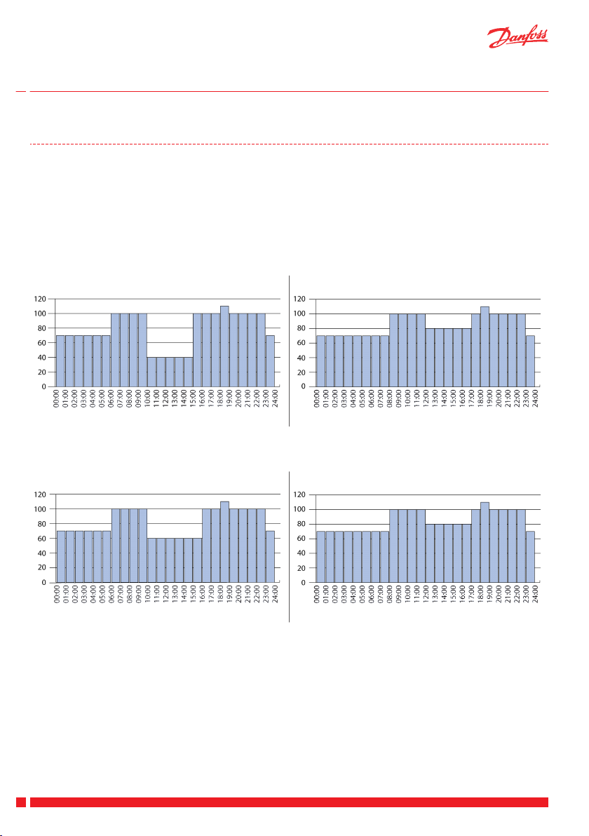
Podręcznik użytkownika Centrale Danfoss Air
3.3 Ustawienia
Menu główne > Ustawienia > Program > Profil 1–5
Przed wybraniem wstępnie zdefiniowanego programu należy aktywować menu Program. W tym celu należy
przejść do następującej lokalizacji: menu główne > Tryb i wybrać opcję Program tyg. Następnie można wybrać
jeden z 5 wstępnie zaprogramowanych profilów, jak pokazano poniżej.
Ponadto można utworzyć własny profil niestandardowy przy użyciu bezpłatnego narzędzia komputerowego
Danfoss, które można pobrać ze strony www.air.danfoss.com. Profil niestandardowy będzie widoczny w menu
w następujący sposób: menu główne > Ustawienia > Program > Profil > Użytkownika.
Profil 1: Rodzina z dziećmi, oboje rodzice pracujący w standardowych godzinach pracy.
Wentylator (% kroku podstawowego) Wentylator (% kroku podstawowego)
Dni powszednie Weekendy
Profil 2: Rodzina z dziećmi, jeden rodzic pracujący w standardowych godzinach pracy, jeden rodzic
przebywający w domu w ciągu dnia.
Wentylator (% kroku podstawowego) Wentylator (% kroku podstawowego)
Dni powszednie Weekendy
58
VUEWA849 Danfoss Heating Solutions
Page 61

Podręcznik użytkownika
Centrale Danfoss Air
Profil 3: Para bez dzieci, obie osoby pracujące w normalnych godzinach pracy.
Wentylator (% kroku podstawowego) Wentylator (% kroku podstawowego)
Dni powszednie Weekendy
Profil 4: Jedna dorosła osoba pracująca, w godzinach pracy nikogo nie ma w domu.
Wentylator (% kroku podstawowego) Wentylator (% kroku podstawowego)
Dni powszednie Weekendy
PL
Profil 5: Małe biuro lub mały punkt sprzedaży. Godziny otwarcia: 8:00–16:00, tylko w dni powszednie.
Wentylator (% kroku podstawowego) Wentylator (% kroku podstawowego)
Dni powszednie Weekendy
Menu główne > Ustawienia > Bypass
W tym menu można ustawić parametry bypassu automatycznego (temperaturę zewnętrzną i temperaturę w
pomieszczeniu). Funkcja bypassu automatycznego jest aktywowana, gdy zarówno temperatura zewnętrzna, jak
i temperatura w pomieszczeniu są wyższe niż wybrany parametr. Jeśli tylko jedna z tych wartości temperatury
jest wyższa, bypass automatyczny nie jest aktywowany.
Aby ręcznie uruchomić bypass, należy wybrać polecenie Bypass. Bypass jest aktywny w okresie wybranym w
następującej lokalizacji: menu główne > Ustawienia > Bypass > Zegar. Ustawienie domyślne to 3 godziny.
Funkcja Bypass nie zostanie aktywowana, jeśli temperatura zewnętrzna spadnie poniżej +5°C.
Uwaga: Funkcje i opcje bypassu są niedostępne w centrali „w1”.
Danfoss Heating Solutions VUEWA849
59
Page 62

Podręcznik użytkownika
Menu główne > Ustawienia > Buster
W tym menu można dostosować funkcję bustera do określonych wymagań:
Ustawienie zegara dla ręcznego bustera (ustawienie domyślne to 3 godziny).
▪
Włączenie lub wyłączenie funkcji Autobuster. Włączenie funkcji Autobuster powoduje jej aktywowanie
▪
we wszystkich trybach.
Zmniejszenie maksymalnego kroku bustera, jeśli domyślny krok maksymalny (10 = 100% prędkości obro-
▪
towej wentylatora) jest zbyt wysoki.
Menu główne > Ustawienia > Czas i data
W tym menu można ustawić datę i godzinę systemu.
Menu główne > Ustawienia > Chł. nocne
W tym menu można włączyć lub wyłączyć funkcję chłodzenia nocnego (domyślnie funkcja jest wyłączona). Kiedy chłodzenie nocne jest włączone, system automatycznie określa, czy bieżący dzień jest dniem ciepłym (temperatura zewnętrzna przekracza 20°C w południe oraz o 16:00). Jeśli dany dzień jest dniem ciepłym, świeże powietrze jest kierowane bezpośrednio do powietrza nawiewanego od północy do 6:00.
Funkcja chłodzenia nocnego jest automatycznie zatrzymywana, kiedy temperatura zewnętrzna spada poniżej
10°C lub jeśli temperatura powietrza usuwanego do otoczenia spada poniżej 18°C.
Uwaga: Funkcja chłodzenia nocnego jest niedostępna w centrali „w1”.
Menu główne > Ustawienia > Ust. domyślne
W tym menu można przywrócić domyślne wartości wszystkich ustawień użytkownika.
Menu główne > Ustawienia > Opcja kominka
Umożliwia włączenie lub wyłączenie opcji kominka. Jeśli w domu jest kominek, opcja kominka może zapobiec
powstawaniu podciśnienia, które może być poważnym zagrożeniem dla ludzi i zwierząt. Kiedy opcja kominka
jest włączona, system Danfoss Air ciągle monitoruje temperaturę i uniemożliwia przejście centrali w tryb rozmrażania (w trybie rozmrażania centrala rozmraża wymiennik ciepła przy bardzo niskiej temperaturze zewnętrznej).
Jeśli temperatura wymaga użycia trybu rozmrażania, automatyczna funkcja zabezpieczająca centrali natychmiast zatrzymuje oba wentylatory na 30 minut, a następnie powoli uruchamia je ponownie i sprawdza temperaturę. Jeśli wartości temperatury są w normie, jest przywracany normalny tryb pracy centrali. W przeciwnym
razie jest ponownie uruchamiana funkcja zabezpieczająca i wentylatory są zatrzymywane na kolejne 30 minut.
W celu uniknięcia problemów z podciśnieniem firma Danfoss zaleca zainstalowanie nagrzewnicy wstępnej
wraz z centralą Danfoss Air (patrz Nagrzewnice).
Centrale Danfoss Air
Regulacja centrali Danfoss Air
Przed pierwszym rozruchem centrali lub w przypadku późniejszego montażu kominka zalecamy wyrównanie
strumieni powietrza nawiewanego i wywiewanego. Pozwala to zapewnić zrównoważony przepływ powietrza.
Zbyt duża ilość powietrza nawiewanego może prowadzić do powstawania nadciśnienia w budynku. Pod żadnym pozorem nie można doprowadzić do takiej sytuacji z powodu ryzyka gromadzenia się nadmiaru wilgoci w
budynku.
Ważne!
Duży okap kuchenny z bezpośrednim wywiewem może zakłócać działanie centrali Air podczas zimy.
Stwierdzenie przepływu zimnego powietrza może oznaczać, że silnik okapu jest mocniejszy od silnika centrali
Air. W centrali Air pojawia się podciśnienie, które jest wyrównywane przez powietrze wlotowe i wylotowe.
60
VUEWA849 Danfoss Heating Solutions
Page 63

2
1
Danfoss
One®
Podręcznik użytkownika Centrale Danfoss Air
Niska temperatura zewnętrzna wpływa na wymiennik ciepła i gdy czujnik temperatury ją wykryje, włączany jest
tryb rozmrażania.
Jeśli temperatura wymaga użycia trybu rozmrażania, automatyczna funkcja zabezpieczająca centrali może zatrzymać oba wentylatory na 30 minut, a następnie powoli uruchomić je ponownie i sprawdzić temperaturę.
Jeśli temperatura będzie prawidłowa, centrala powróci do normalnego trybu pracy. W przeciwnym razie zostanie ponownie uruchomiona funkcja zabezpieczająca i wentylatory zostaną zatrzymane na kolejne 30 minut.
W celu zapobiegania problemom z podciśnieniem Danfoss zaleca, aby:
1. Zainstalować w kuchni przepustnicę.
2. Otwierać okno na czas korzystania z okapu kuchennego.
Uwaga: W przypadku występowania problemów związanych z podciśnieniem należy skontaktować się z monterem i
zapytać, czy przepustnica jest zainstalowana.
Podciśnienie jest częstym problemem w budynkach nowo wybudowanych i z poprawioną izolacją.
Warunki prawne
Instalacja systemu Danfoss Air musi być zawsze przeprowadzana zgodnie z krajowymi, regionalnymi lub lokalnymi przepisami i rozporządzeniami.
3.4 Wymiana baterii sterownika Air Dial
O konieczności wymiany baterii sterownika Air Dial informuje odpowiedni
alarm dźwiękowy.
Należy zdjąć sterownik Air Dial ze wspornika naściennego i wymienić cztery
baterie typu AAA.
PL
4 Sterowanie centralą Air za pomocą panelu centralnego Danfoss Link™ CC
Jeśli centrala rekuperacyjna jest sterowana za pośrednictwem panelu
centralnego Danfoss Link™ CC, ogólne informacje i instrukcje dotyczące
central rekuperacjnych w systemie Danfoss One® można znaleźć w podręczniku na stronie www.link.danfoss.com.
Danfoss Heating Solutions VUEWA849
61
Page 64

Podręcznik użytkownika Centrale Danfoss Air
5 Wymiana filtrów
Centrale Danfoss Air zostały zaprojektowane tak, aby wymagały możliwie najmniej czynności konserwacyjnych.
Konserwacja ogranicza się do jednej lub dwóch wymian filtrów w roku, w zależności od wydajności powietrza i
poziomu zanieczyszczenia powietrza.
W obszarach przemysłowych i miejscach o wysokim stężeniu pyłków w powietrzu filtry zatykają się szybciej niż
w typowym środowisku podmiejskim.
Centrale Danfoss Air są wyposażone w oryginalne filtry chroniące urządzenie i zapewniające komfort. Zostały
one przetestowane i zatwierdzone, dzięki czemu chronią również podzespoły wewnętrzne, takie jak wymiennik
ciepła i wentylatory. W przypadku użycia nieoryginalnych filtrów firma Danfoss nie może zagwarantować pełnej jakości i żywotności podzespołów wewnętrznych.
Filtry standardowe i opcjonalne filtry przeciwpyłowe (klasa F7) można kupić u montera.
O konieczności wymiany filtrów informuje odpowiedni alarm sterownika Air Dial (dźwięk alarmu i komunikat na wyświetlaczu):
1. Zdejmij przedni panel (nie są potrzebne żadne narzędzia).
2. Wyjmij filtry i sprawdź je wzrokowo.
3. Jeśli filtr jest tylko lekko zanieczyszczony lub przebarwiony, możesz spróbować go wyczyścić przy użyciu
odkurzacza ze szczotką. Zazwyczaj takie rozwiązanie nie jest skuteczne ani zalecane.
4. Włóż nowe filtry* i załóż osłony piankowe.
5. Naciśnij przycisk resetu filtra w przedniej części centrali.
* Jeśli zakupiono specjalny filtr przeciwpyłowy, należy go umieścić w miejscu na filtr po prawej stronie (we wszystkich
modelach), ponieważ służy on do filtrowania powietrza świeżego.
Standardowy zestaw filtrujący
Standardowy zestaw filtrujący obejmuje filtry klasy G4 dla powietrza nawiewanego i wywiewanego, co zapewnia podstawowy poziom filtrowania cząstek o rozmiarze większym niż 10 μm.
Nr katalogowy
Standardowy zestaw filtrujący G4/G4 dla centrali Danfoss Air w¹ 089F0238
Standardowy zestaw filtrujący G4/G4 dla centrali Danfoss Air w² 089F0239
Standardowy zestaw filtrujący G4/G4 dla centrali Danfoss Air a² 089F0236
Standardowy zestaw filtrujący G4/G4 dla centrali Danfoss Air a³ 089F0237
Zestaw filtrów przeciwpyłowych
Jeśli w rodzinie są alergicy, należy wybrać zestaw filtrów przeciwpyłowych z filtrem klasy F7, który skutecznie
odfiltruje pyłki z powietrza nawiewanego.
Nr katalogowy
Zestaw filtrów przeciwpyłowych G4/F7 dla centrali Danfoss Air w¹ 089F0242
Zestaw filtrów przeciwpyłowych G4/F7 dla centrali Danfoss Air w² 089F0243
Zestaw filtrów przeciwpyłowych G4/F7 dla centrali Danfoss Air a² 089F0240
Zestaw filtrów przeciwpyłowych G4/F7 dla centrali Danfoss Air a³ 089F0241
62
VUEWA849 Danfoss Heating Solutions
Page 65

Podręcznik użytkownika Centrale Danfoss Air
6 Czyszczenie centrali Danfoss Air
Wnętrze centrali Danfoss Air należy czyścić raz na dwa lata.
1. Odłącz zasilanie i zdejmij panel przedni.
2. Odkręć sześć śrub mocujących trzy metalowe szyny przy użyciu odpowiedniego wkrętaka Torx.
3. Zdejmij przedni panel piankowy, aby uzyskać dostęp do wewnętrznych
podzespołów centrali.
PL
4. Wyjmij bokiem grube, owalne uszczelnienie wymiennika ciepła. Podczas
ponownego montażu wymiennika to uszczelnienie należy zamontować
jako ostatnie. W tym celu najlepiej najpierw zablokować dwa końce, a
następnie wepchnąć pozostałą część uszczelnienia.
Danfoss Heating Solutions VUEWA849
63
Page 66

Podręcznik użytkownika
5. Teraz można ostrożnie unieść i wyjąć wymiennik ciepła z urządzenia.
6. Wlej łagodny roztwór płynu do mycia naczyń przez cztery otwory wymiennika ciepła. Zaczekaj 5–10 minut na spłynięcie roztworu, a następnie opłucz wymiennik w bieżącej wodzie. Osusz obudowę wymiennika ciepła i delikatnie wsuń wymiennik do centrali.
Wyczyść wnętrze centrali przy użyciu wilgotnej gąbki lub ścierki (użyj łagodnego roztworu mydlanego).
Pod żadnym pozorem nie czyść części piankowych przy użyciu rozpuszczalników, ponieważ mogą one
rozpuścić piankę.
Nie dopuszczaj do kontaktu głównej płytki obwodów z wodą. W przypadku oblania płytki wodą osusz
ją delikatnie przy użyciu suchej ścierki i pozostaw do wysuszenia na co najmniej 24 godziny przed ponownym podłączeniem zasilania.
Złóż centralę w odwrotnej kolejności:
1. Załóż przedni panel piankowy.
2. Zabezpiecz panel przy użyciu trzech metalowych szyn.
3. Przykręć śruby przy użyciu wkrętaka Torx.
4. Ponownie zamocuj panel przedni.
Centrale Danfoss Air
Urządzenie jest teraz gotowe do bezawaryjnej pracy przez kolejne dwa lata.
64
VUEWA849 Danfoss Heating Solutions
Page 67

3
4
1
2
+
3
4
1
2
+
Podręcznik użytkownika Centrale Danfoss Air
7 Nagrzewnice
Nagrzewnica wstępna zapewnia wiele korzyści dla systemu Danfoss Air i ogólnego komfortu cieplnego. Firma
Danfoss zawsze zaleca zainstalowanie nagrzewnicy wstępnej wraz z centralą Danfoss Air.
Nagrzewnica wstępna chroni system przed automatycznym przełączaniem w tryb rozmrażania, co może powodować powstawanie podciśnienia w budynku — zwłaszcza jeśli w budynku jest kominek.
Elektryczna nagrzewnica wstępna
1. Powietrze świeże
2. Nawiew
3. Wyciąg
4. Wywiew
Elektryczna nagrzewnica wstępna chroni system przed oblodzeniem przy niskiej temperaturze zewnętrznej.
Zanim powietrze świeże dotrze do systemu, jest ogrzewane od bieżącej temperatury zewnętrznej do 0°C (co
uniemożliwia zamarzanie wymiennika). Takie rozwiązanie zapewnia stałą równowagę między powietrzem nawiewanym i wywiewanym. Regulacja jest w pełni bezkrokowa w celu zapewnienia najniższego możliwego
poboru mocy podczas działania. Elektryczna nagrzewnica wstępna nie wymaga konfigurowania żadnych ustawień.
Elektryczna nagrzewnica powietrza nawiewanego
PL
1. Powietrze świeże
2. Nawiew
3. Wyciąg
4. Wywiew
Elektryczna nagrzewnica powietrza nawiewanego zapewnia minimalną temperaturę powietrza nawiewanego
przed doprowadzeniem powietrza do pomieszczenia. System wentylacji zazwyczaj ogrzewa powietrze świeże
do wartości zbliżonej do temperatury w pomieszczeniu, dzięki czemu elektryczna nagrzewnica wtórna służy
tylko do nieznacznego zwiększenia temperatury powietrza nawiewanego. Regulacja jest w pełni bezkrokowa
w celu zapewnienia najniższego możliwego poboru mocy podczas działania.
Temperaturę powietrza nawiewanego można ustawić za pomocą sterownika Air Dial w następującej lokalizacji: menu główne > Ustawienia > Temperatura > Nawiew.
Danfoss Heating Solutions VUEWA849
65
Page 68

4
1
5
3
2
+
6
3
2
4
1
Podręcznik użytkownika Centrale Danfoss Air
Wodna nagrzewnica powietrza nawiewanego
1. Powietrze świeże
2. Nawiew
3. Wyciąg
4. Wywiew
5. Pompa
6. Centralne ogrzewanie
Wodna nagrzewnica powietrza nawiewanego najczęściej zapewnia minimalną temperaturę powietrza nawiewanego przed doprowadzeniem powietrza do pomieszczenia. System wentylacji zazwyczaj ogrzewa powietrze świeże do wartości zbliżonej do temperatury w pomieszczeniu, dzięki czemu wodna nagrzewnica powietrza nawiewanego służy tylko do nieznacznego zwiększenia jego temperatury.
W pełni bezkrokowa regulacja jest przeprowadzana za pomocą wbudowanego siłownika zaworu.
Temperaturę powietrza nawiewanego można ustawić za pomocą sterownika Air Dial w następującej lokalizacji: menu główne > Ustawienia > Temperatura > Nawiew.
W szczególnych przypadkach nagrzewnica powietrza nawiewanego może zapewniać całe ogrzewanie w domach pasywnych lub domach energooszczędnych, jeśli wymiary wszystkich części systemu zostały odpowiednio dostosowane. Jeśli system został skonfigurowany na potrzeby ogrzewania powietrza, temperaturę
pomieszczenia można ustawić w menu głównym.
Geotermalna nagrzewnica/chłodnica wstępna
1. Powietrze świeże
2. Nawiew
3. Wyciąg
4. Wywiew
5. Pompa
Nagrzewnica/chłodnica geotermalna umożliwia wstępne ogrzanie lub schłodzenie powietrza świeżego w zależności od pory roku. Sterownik automatycznie określa wymaganą funkcję i włącza lub wyłącza nagrzewnicę/chłodnicę w zależności od potrzeb. Nagrzewnica/chłodnica geotermalna jest zasilana przez czynnik chroniący przed zamarzaniem (czynnik pośredni), który jest tłoczony w rurze podziemnej za pomocą pompy obiegowej. Umożliwia to korzystanie z bezpłatnej energii odnawialnej z czystym sumieniem.
Zimą ogrzewanie wstępne uniemożliwia przełączanie systemu w tryb ochrony przeciwzamrożeniowej, natomiast latem zapewnia dodatkowe przyjemne chłodzenie przez chłodzenie powietrza przed jego dotarciem
do systemu. Kiedy urządzenie działa jako chłodnica geotermalna, bypass systemu wentylacji jest otwierany
automatycznie.
66
VUEWA849 Danfoss Heating Solutions
Page 69

Podręcznik użytkownika Centrale Danfoss Air
8 Sterowanie za pomocą komputera
Systemem DANFOSS AIR można sterować za pomocą komputera przez sieć Ethernet.
Tworzenie dostosowanych programów tygodniowych przy użyciu przyjaznego dla użytkownika edytora
▪
programów tygodniowych.
Monitorowanie oraz wyświetlanie wszystkich wartości temperatury i wilgotności względnej w budynku w
▪
jednym widoku.
Wyświetlanie krzywych trendów z ostatnich 14 dni — dane wszystkich ważnych czujników są rejestrowa-
▪
ne co godzinę.
Łatwy dostęp do ustawień zaawansowanych — wszystkie funkcje są przedstawione za pośrednictwem
▪
krótkiego i zrozumiałego tekstu.
Pobierz bezpłatne narzędzie komputerowe Danfoss Air ze strony www.air.danfoss.com.
Uwaga: Jeśli używany jest panel centralny Danfoss Link™ CC, opcje w narzędziu komputerowym Danfoss Air są ograniczone.
PL
9
Rozwiązywanie problemów
Błąd Przyczyna Rozwiązanie
Alarm: Błąd filtra Filtry powietrza są brudne. Wymień filtry powietrza.
Alarm: Niski stan
naładowania baterii
Alarm: Brak łącz-
ności z modułem
komunikacyjnym
CCM
Alarm: Brak połączenia Modbus
Napięcie baterii sterownika Air Dial jest
zbyt niskie.
Utracono komunikację między sterownikiem Air Dial a modułem komunikacyjnym
CCM, co zwykle jest spowodowane obecnością przeszkody między elementami, na
przykład rurociągów stalowych, innych
obiektów stalowych, osłony materiału izolacyjnego z folią aluminiową itp. Inną przyczyną problemu może być praca innego
urządzenia bezprzewodowego, które nie
odpowiada właściwym normom (emitując
zakłócenia radiowe).
Kabel łączący moduł komunikacyjny CCM
z centralą został odłączony lub jest uszkodzony.
Wymień 4 baterie typu AAA w sterowniku
Air Dial.
Jeżeli znajdziesz przeszkodę, usuń ją. Jeżeli nie jest to możliwe, przenieś moduł komunikacyjny CCM w miejsce zapewniające
bezpośrednią widoczność radiową.
Jeżeli błąd występuje z powodu działania
innych urządzeń bezprzewodowych w budynku, wyłączaj je kolejno, aby znaleźć
przyczynę.
Jeżeli żadne z powyższych rozwiązań nie
pozwoliło rozwiązać problemu, skontaktuj
się z monterem.
Sprawdź kabel i podłącz go, jeżeli to konieczne. Jeżeli kabel jest podłączony i błąd
nadal występuje, skontaktuj się z monterem.
Alarm: Powietrze w
pomieszczeniu jest
zbyt zimne
Układ centralnego ogrzewania nie wytwarza ciepła. Temperatura w pomieszczeniu
spada, więc centrala wyłącza się w celu
ograniczenia strat ciepła. Alarm włącza się,
gdy sterownik Air Dial wykryje spadek
temperatury w pomieszczeniu poniżej
+10°C.
Sprawdź, czy układ centralnego ogrzewania działa. Jeżeli nie można rozwiązać
problemu, wezwij hydraulika/montera.
Jeżeli błąd został usunięty, wyłącz i ponownie uruchom system wentylacji w celu
przywrócenia jego normalnego działania.
Zasilanie można odłączyć przez wyciągnięcie kabla zasilania z gniazdka.
Danfoss Heating Solutions VUEWA849
67
Page 70

Podręcznik użytkownika Centrale Danfoss Air
Błąd Przyczyna Rozwiązanie
Alarm: Pożar Jeden z czterech czujników temperatury
centrali Danfoss Air lub czujnik temperatury w zdalnym sterowniku Air Dial wykrył,
że temperatura przekracza +70°C. Centrala
wyłącza się, gdy wszystkie czujniki wykrywają temperaturę powyżej +70°C.
Alarm: Błąd czujni-kaCzujnik temperatury w centrali Danfoss Air
lub sterowniku Air Dial jest uszkodzony.
Alarm: Powietrze
nawiewane jest zbyt
zimne
Czujnik powietrza nawiewanego wykrył
spadek temperatury powietrza nawiewanego poniżej +5°C. Centrala jest automatycznie zatrzymywana w celu zapobiegnięcia niepożądanemu ochłodzeniu budynku. Jest to spowodowane podciśnieniem, które powstało w wyniku działania
elementów zewnętrznych, na przykład
okapu z bezpośrednim wywiewem.
Alarm: Zatrzymanie
pracy z powodu kominka
Aktywowanie funkcji optymalizacji pod
kątem kominka powoduje zatrzymanie
centrali z powodu ryzyka wystąpienia
podciśnienia.
Niezwykle wysokie
podciśnienie wewnątrz budynku,
opór stawiany przez
drzwi
Przepływ powietrza wywiewanego jest
większy niż przepływ powietrza nawiewanego. Nie wykonano prawidłowego zrównoważenia podczas konfiguracji instalacji
lub centrala pracuje w ekstremalnych warunkach rozmrażania (na przykład przy
temperaturze zewnętrznej poniżej -12°C).
Sprawdź wszystkie pomieszczenia i opuść
budynek.
Jeżeli błąd został usunięty, wyłącz i ponownie uruchom system wentylacji w celu
przywrócenia jego normalnego działania.
Zasilanie można odłączyć przez wyciągnięcie kabla zasilania z gniazdka.
Skontaktuj się z monterem.
System będzie działać z pewnymi ograniczeniami.
Wyłącz i ponownie uruchom centralę.
Sprawdź, które urządzenie w domu jest
przyczyną alarmu. Firma Danfoss zaleca
zainstalowanie nagrzewnicy wstępnej
i/lub używanie urządzeń domowych z recyrkulacją powietrza. Aby uzyskać więcej
informacji, skontaktuj się z monterem.
Centrala jest zatrzymywana na 30 minut, a
następnie są sprawdzane wszystkie temperatury. Jeśli wartości temperatury są w
normie, następuje ponowne uruchomienie centrali. W przeciwnym razie centrala
będzie powtarzać ten proces do czasu
uzyskania wszystkich wartości temperatury w prawidłowym zakresie.
Trwałym rozwiązaniem może być zainstalowanie nagrzewnicy wstępnej. Aby uzyskać więcej informacji, skontaktuj się z
monterem.
Nierównowaga przepływu powinna wynosić od 4% do 10% (większa wartość dla powietrza wywiewanego). Jeśli jednak drzwi
będą nadal stawiały opór z powodu podciśnienia, skontaktuj się z monterem.
Jeżeli problemy występują wyłącznie podczas ostrej zimy, ich powodem jest wbudowany sterownik rozmrażania, który
zmniejsza ilość powietrza nawiewanego,
co nie jest wadą, lecz normalnym (acz bardzo rzadkim) zjawiskiem.
68
VUEWA849 Danfoss Heating Solutions
Page 71

Podręcznik użytkownika Centrale Danfoss Air
Błąd Przyczyna Rozwiązanie
Woda skrapla się na
ramach okiennych
Temperatura wewnątrz budynku jest
zbyt wysoka
Centrala hałasuje Centrala typu a: Jeżeli centrala jest instalo-
Hałas wydobywający się z anemostatów
Jest wyświetlana
ikona mrozu
Intensywność wymiany powietrza jest
zbyt niska. Woda skrapla się, gdy temperatura powierzchni jest niska, a wilgotność
powietrzna jest wysoka, co zachodzi zwyk-
Zwiększ prędkość wentylatora (w trybie
ręcznym) lub przełącz centralę w tryb na
żądanie lub tryb programu.
Włącz funkcję Autobuster.
le w łazienkach lub pomieszczeniach gospodarczych, np. w pralni, gdzie powieszono odzież do odcieknięcia (skraplanie się
wody w niewielkich ilościach jest normalne w łazience tuż po prysznicu, ale zjawisko powinno ustąpić w ciągu pół godziny).
Ustawienia termostatów w budynku są
Zmniejsz ustawienia termostatów.
zbyt wysokie.
Bypass został wyłączony w systemie wentylacji.
Włącz bypass w następującej lokalizacji:
menu główne > Bypass > Auto bypass.
Upewnij się, że centrala została zainstalowana bezpośrednio na belkach stropowych, może pojawić się hałas spowodo-
wana na podeście zgodnie z podręczni-
kiem montażu.
wany drganiami. Należy zainstalować centralę na odpowiednim podeście.
Centrala typu w: Jeżeli między centralą a
ścianą nie zainstalowano gumowych przekładek i/lub na wsporniku naściennym nie
Upewnij się, że założono przekładki gumo-
we i listwę silikonową zgodnie z podręcz-
nikiem montażu.
założono listwy silikonowej, może występować hałas spowodowany drganiami.
Uszkodzone łożyska wentylatorów powodują zgrzytanie.
Jeżeli łożysko kulowe może być uszkodzo-
ne, skontaktuj się z monterem.
Przepływ powietrza jest zbyt duży. Hałas nie występuje w prawidłowo zwyCiśnienie na anemostacie jest zbyt wyso-
kie.
Na kanale głównym nie zainstalowano tłu-
mika.
System działa w trybie rozmrażania, po-
nieważ niska temperatura zewnętrzna
grozi oblodzeniem wymiennika ciepła.
miarowanym i uruchomionym systemie.
Jeżeli jednak anemostaty są zamknięte
(np. podczas czyszczenia), system może
syczeć.
Nie jest to błędem, lecz normalnym try-
bem pracy. Ta funkcja wyłączy się automa-
tycznie, gdy temperatura zewnętrzna
wzrośnie.
PL
Danfoss Heating Solutions VUEWA849
69
Page 72

User Guide Danfoss Air Units
Danfoss A/S
Heating Solutions
Ulvehavevej 61
7100 Vejle
Denmark
Phone: +45 7488 8500
Fax: +45 7488 8501
Email: heating.solutions@danfoss.com
www.heating.danfoss.com
Danfoss can accept no responsibility for possible errors in catalogues, brochures and other printed material. Danfoss reserves the right to alter its products without notice. This also applies to products
already on order provided that such alterations can be made without subsequential changes being necessary in specifications already agreed. All trademarks in this material are property of the respective
companies. Danfoss Heating Solutions and the Danfoss Heating Solutions logotype are trademarks of Danfoss A/S. All rights reserved.
VUEWA802 Produced by Danfoss Heating Solutions © 08/2013
 Loading...