

Page 1
MAKING MODERN LIVING POSSIBLE
User Guide
AirCalc Dimensioning Tool
www.heating.danfoss.com
Page 2

The English language is used for the original instructions.
Other languages are a translation of the original instructions.
(Directive 2006/42/EC)
© 2011 Copyright Danfoss A/S
Page 3
User Guide AirCalc Dimensioning Tool
Table of Contents
1 Introduction to AirCalc ............................................................ 3
1.1 Start-up ................................................................... 3
1.2 Create Project ............................................................... 4
1.3 Open an Existing Project ......................................................... 4
1.4 Delete an Existing Project ........................................................ 4
1.5 Search for a Project ............................................................ 4
1.6 Left Menu Set-up ............................................................. 5
2 Dimensioning ................................................................... 5
2.1 Dimensioning Menu ........................................................... 5
2.2 Extract .................................................................... 6
2.3 Supply .................................................................... 9
2.4 Outlet .................................................................... 9
2.5 Inlet ...................................................................... 10
2.6 Unit Selection ............................................................... 11
2.7 Accessories ................................................................. 12
3 Reports ....................................................................... 12
3.1 Unit Result ................................................................. 12
3.2 Report .................................................................... 13
4 System ....................................................................... 13
4.1 Settings ................................................................... 14
4.2 Pressure Loss Template ......................................................... 15
4.3 Room Names ................................................................ 15
1 Introduction to AirCalc
Danfoss AirCalc is a dimensioning tool, specifically developed for
the dimensioning of Danfoss Air units and Danfoss Air Flex products.
Danfoss AirCalc calculates the pressure loss of your entire Air Flex
system, but also down to component level if desired. The program
also offers a suggestion as to which unit would constitute the ideal
choice based on entered data.
Based on the calculated pressure loss and the selected unit, a presetting is calculated for valves, the pre-setting of valve increments
for the selected unit, as well as the SFP value and energy consumption.
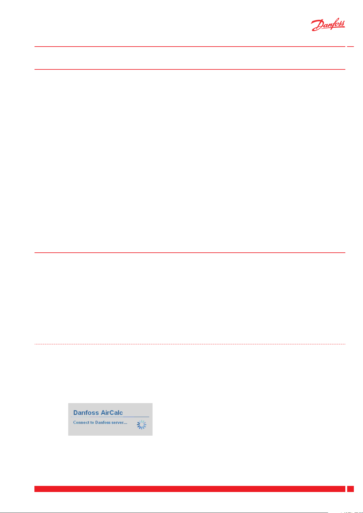
1.1 Start-up
Once Danfoss AirCalc is started up, the programme will immediately attempt to establish a connection to a Danfoss server.
If a network connection is found, the program will automatically
search for available updates. If an update is found for the programme, it will be automatically downloaded and installed.
If the programme is started from a PC without a network connection, the programme will search for a server for approximately 15
seconds and then start normally.
With the flexible report generator, print-outs can be fully managed
by the user so that the generated report contains only the pages
desired. This means everything from basic information to complete documentation, including all data sheets for products that
form part of the system.
Danfoss Heating Solutions VUFKC102
3
Page 4
User Guide AirCalc Dimensioning Tool
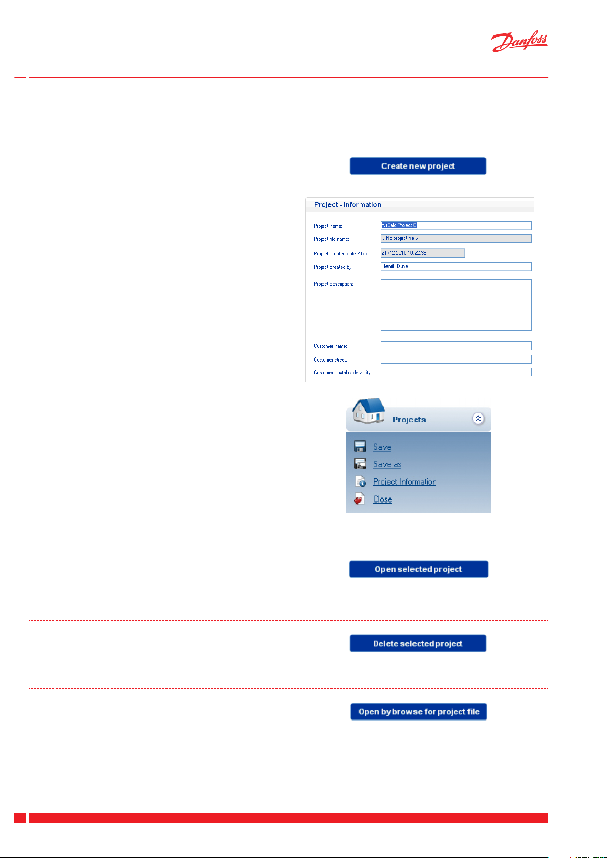
1.2 Create Project
After start-up, the first step is to create a project with the appertaining information.
1. Click on "Create new product".
2. Next, fill in the fields with the relevant project data.
3. Once the project data has been entered, save the project by
clicking "Save" in the "Projects" menu.
Final dimensioning can then be started.
1.3 Open an Existing Project
To open an existing project, select the project in the overview and
click "Open selected project" in the right menu. Alternatively, simply double-click on the desired project in the project overview.
1.4 Delete an Existing Project
To delete an existing project, select the project in the overview
and click "Delete selected project".
1.5 Search for a Project
If a project does not appear in the project overview, the project file
can be searched for as normal by clicking "Open by browse for
project file".
4
VUFKC102 Danfoss Heating Solutions
Page 5
User Guide AirCalc Dimensioning Tool
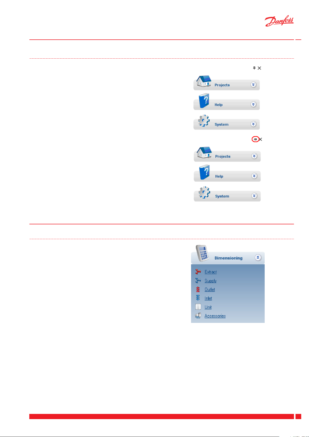
1.6 Left Menu Set-up
As can be seen in the picture to the left, there are two small icons
in the top right corner: a thumb tack and an X.
When you click the X, the left menu will be closed until the mouse
is again led over the edge of its frame, after which the menu will
once again become visible.
When you click the thumb tack icon, the menu will close automatically once the mouse is directed away from the menu. This function is active when the thumb tack's tip changes position from
pointing to the bottom of the screen to pointing to the left.
2 Dimensioning
2.1 Dimensioning Menu
Once a project has been created, access is granted to the dimensioning menu on the left side.
The menu's individual options are explained in the following.
NOTE: The order for extract and supply does not matter, but these
should always be completed before calculating outlet and inlet.
Danfoss Heating Solutions VUFKC102
5
Page 6

User Guide AirCalc Dimensioning Tool
2.2 Extract
Click "Extract" and the dimensioning can begin.
Create Room
To add a room, click the green plus sign.
By clicking on the red cross a created room can be erased, and by
clicking on the "information icon" at the bottom the number of
displayed information columns expands to the maximum (here we
see six columns).
Next, open the "Add new room" dialogue box, where a pre-defined room can be selected (see "Room names" section).
A room name can also be entered as desired.
If a pre-defined room is selected from the list, both room name
and air volume will be transferred to "Room settings".
Selecting a Box
Select the desired box type. The possible options appear when
you click the "Select product" icon.
In the "Select product" box, choose the desired box by selecting it
and clicking "OK".
6
VUFKC102 Danfoss Heating Solutions
Page 7

User Guide AirCalc Dimensioning Tool
The selected box will then be displayed in "Room settings".
Valve Selection
Select the desired valve. The possible options appear when you
click the "Select product" icon.
If only one eligible product is available, it will be automatically selected.
Flex Pipe Selection
Select the desired dimension. The possible options appear when
you click the "Select product" icon.
If only one eligible product is available, it will be automatically selected.
NOTE: To the extent possible, the program will automatically select
the dimension which fits the selected box.
NOTE: The flex pipe is currently only available in Ø75, and it will therefore be pre-selected.
Enter Flex Pipe Data
Once the box, valve and pipe have been selected, the final pipe
data must be entered:
1. Number of pipes to be connected to the box
2. Length of the individual pipe
3. Number 90-degree bends in the pipe
4. Flow per pipe (flow in room divided by the number of pipes)
5. Pressure loss in the pipe (as a function of flow, length and the
number of bends)
The first room is newly created and all data is saved in the overview.
All subsequent rooms are created in the same way.
Danfoss Heating Solutions VUFKC102
7
Page 8

User Guide AirCalc Dimensioning Tool
Overview
1. Room name
2. Flow for the selected room
3. Select box type for room
4. Pressure loss over box (by the indicated air volume)
5. Selected fittings for room
6. Selected flex pipe for room
7. Number of pipes connected to the box
8. Length of an individual pipe
9. Air volume per pipe
10. Number of 90-degree bends (per pipe)
11. Pressure loss in pipe (by the indicated air volume)
Manifold (Extract)
Once all the room have been entered, click "Next" in the bottom
right-hand corner.
Which type/how many manifolds used must now be selected
As shown in the picture, one, two or more manifolds can be selected.
Select the desired number and click "Next" in the bottom righthand corner.
Manifold Type
As seen in the picture below, all room are automatically selected
when only one manifold is selected.
Pressure Loss From Unit to Manifold
The duct from unit to manifold is defined here.
Select dimension
▪
Enter the duct length from unit to manifold
▪
Enter the number of 90-degree bends in the duct length
▪
If products mounted to the duct length cannot be selected,
▪
the pressure loss can be entered under "User defined pressure loss".
To enter silencers, click the box next to "Include silencer" and select the silencer as usual.
8
VUFKC102 Danfoss Heating Solutions
Page 9
User Guide AirCalc Dimensioning Tool
Results
Finally, a results overview will be displayed.
Here an overview is shown with the greatest number of key data
for extraction.
The final column, "Pre-balancing" is a pre-calculated valve setting
which indicates how many rotations the individual valve will open.
2.3 Supply
Supply is dimensioned precisely as "Extract" (see section 2.2).
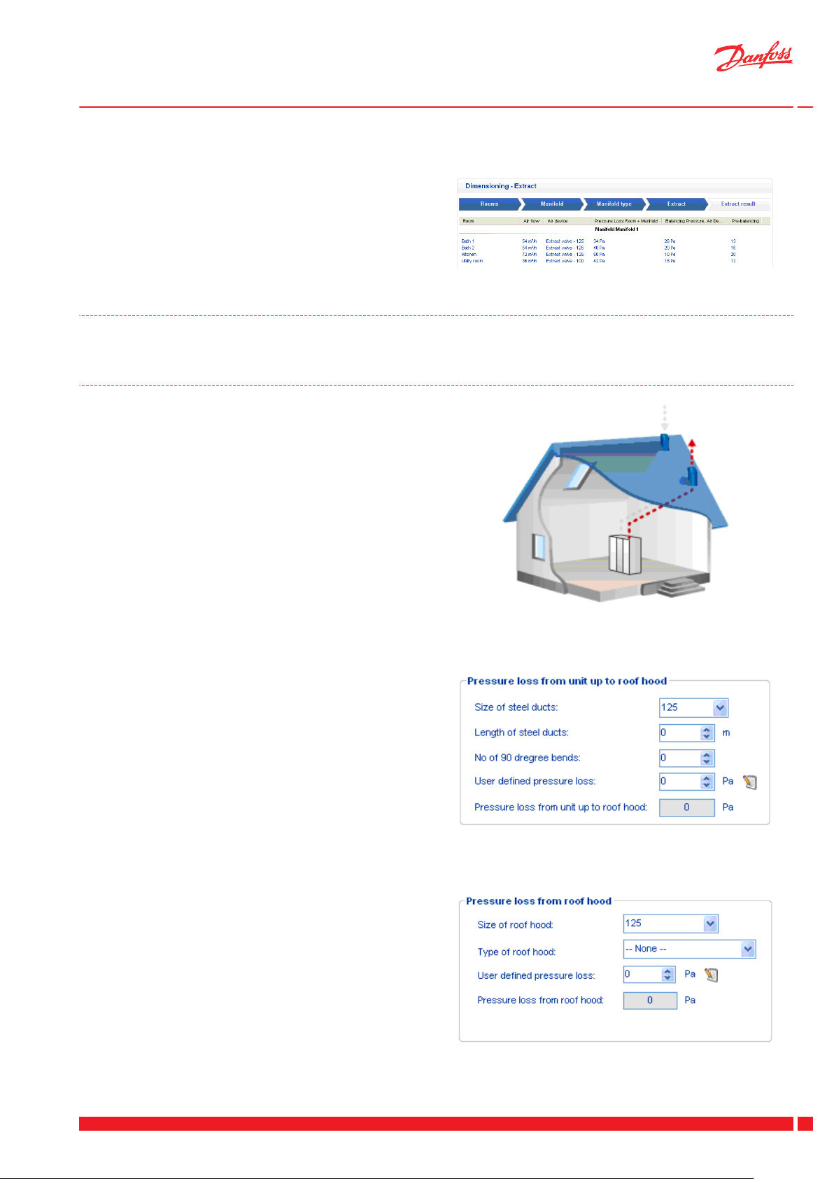
2.4 Outlet
Outlet is defined as the duct length from the unit to the roof hood.
Pressure Loss, Duct Length
1. Start by selecting the dimension of the ducts connecting the
unit to the roof hood.
2. Indicate the duct's length.
3. Indicate the number of 90-bends in the duct length.
4. If components are mounted in the duct length which cannot
be selected on the list, a user-defined pressure loss can be entered here. Alternatively, these components can be created
and subsequently selected from a list by clicking the little
icon to the right of the box.
The total pressure loss will then be calculated.
Pressure Loss, Roof Hood
1. Begin by selecting the hood's dimensions.
2. Next, select the hood type.
3. If the desired hood is not available on the list, a user-defined
pressure loss for the roof hood used can be entered. Alternatively, these components can be created and subsequently
selected from a list by clicking the little icon to the right of
the box (see section on "Pressure loss templates").
The pressure loss for the hood will then be calculated.
Danfoss Heating Solutions VUFKC102
9
Page 10

User Guide AirCalc Dimensioning Tool
2.5 Inlet
Inlet is defined as the duct length from the unit to the roof hood.
Pressure Loss, Duct Length
As described in 2.4.
Pressure Loss From Preheating Surface
If a preheating surface is installed in the system, select it here.
Pressure Loss, Roof Hood
As described in 2.4.
10
VUFKC102 Danfoss Heating Solutions
Page 11

User Guide AirCalc Dimensioning Tool
2.6 Unit Selection
House Type
Start by selecting the house type along with the total area of the
house.
Unit Type
Select the unit type - attic or wall model.
Recommendations
Based on the data entered, the program will suggest which is the
ideal unit to be used.
To use a different unit than the one selected, click the "Choose different unit" box, and the desired unit will be selected and used in
the calculation.
Danfoss Heating Solutions VUFKC102
11
Page 12

User Guide AirCalc Dimensioning Tool
2.7 Accessories
Select accessories from the list. Enter the desired quantity based
on the product, and this will subsequently appear in the bill of materials.
3 Reports
Under "Reports", the program's report is created and can be adjusted based on the user's specifications.
3.1 Unit Result
The unit's key figures appear on the "Unit result" page.
The selected unit type
▪
Total air volume for the respective supply air and extraction
▪
Total external pressure loss for respective supply air + intake
▪
and extraction + exhaust.
Expected fan increments for respective supply and exhaust
▪
fans.
SFP value
▪
Total power consumption
▪
Annual power consumption
▪
12
VUFKC102 Danfoss Heating Solutions
Page 13

User Guide AirCalc Dimensioning Tool
3.2 Report
As seen below, all information can be selected and can be freely selected and deselected by the user.
When the desired information is selected, click "Generate report",
after which the program will automatically generate a PDF file,
which can be saved or printed.
To include the data sheet for the individual products in the report,
select "Product information sheets", after which the data sheets
will be activated and can subsequently be selected.
A bill of materials can also be generated in the PDF file. This is
done by selecting "Project bill of materials".
4 System
All standard configurations can be performed in the "System"
menu.
To transfer the bill of materials to Excel for further processing, first
select "Project bill of materials", after which the "Export project
BOM to clipboard" option will be activated and can be selected.
Next, open Excel and insert. Your bill of materials will then be
transferred to the Excel spreadsheet.
Danfoss Heating Solutions VUFKC102
13
Page 14

User Guide AirCalc Dimensioning Tool
4.1 Settings
The general values and the like for AirCalc can be entered in "System settings".
1. "Maximum pressure loss (per room)" provides the user with the option to enter the pressure loss value for which an alarm is to be
given.
2. "Default project folder" is the path by which AirCalc will search for project files. All AirCalc files located in the selected path or subfolders will then be displayed in the project overview.
3. Option for selecting between the flow units, m3/h and l/s.
4. "AirCalc Engineer information": These fields must be filled out before the automatic update will function.
14
VUFKC102 Danfoss Heating Solutions
Page 15

User Guide AirCalc Dimensioning Tool
4.2 Pressure Loss Template
"Pressure loss template" is used when the user wishes to create and save one or more products which are not available in the program.
Example:
To use a roof hood that is not available in AirCalc:
1. Select "Roof hood"
2. Click the green "+" on the right side, after which the "User
pressure loss settings" dialogue box will appear.
3. Fill in the fields.
4. Click "OK".
5. The roof hood will now be visible under "Roof hood" and can
be used once pressure loss has been calculated for "Inlet" and
"Outlet".
4.3 Room Names
In "Room names", the desired number of rooms with appertaining air volumes can be defined.
Note:
Separate products will not appear in the bill of materials, but will
only figure into the pressure loss calculation.
The number of desired rooms for diffusion and extraction can be
entered.
Click the green "+" and enter the room name and desired air volume in the table.
Example:
If there are specific legal requirements concerning the volume of
air that must be extracted, the specified volume can be set as a default value.
It will then be possible to select the established rooms in "Room
settings" and the pre-selected flow will be automatically entered.
Danfoss Heating Solutions VUFKC102
15
Page 16

User Guide AirCalc Dimensioning Tool
Danfoss A/S
Heating Solutions
Ulvehavevej 61
7100 Vejle
Denmark
Phone:+45 7488 8500
Fax: +45 7488 8501
Email: heating.solutions@danfoss.com
www.heating.danfoss.com
Danfoss can accept no responsibility for possible errors in catalogues, brochures and other printed material. Danfoss reserves the right to alter its products without notice. This also applies to products
already on order provided that such alterations can be made without subsequential changes being necessary in specifications already agreed. All trademarks in this material are property of the respective
companies. Danfoss Heating Solutions and the Danfoss Heating Solutions logotype are trademarks of Danfoss A/S. All rights reserved.
VUFKC102 Produced by Danfoss Heating Solutions © 03/2011
 Loading...