

User Guide
Capacity controller for CO
mini pack
AK-PC 572
ADAP-KOOL® Refrigeration Control System
Introduction
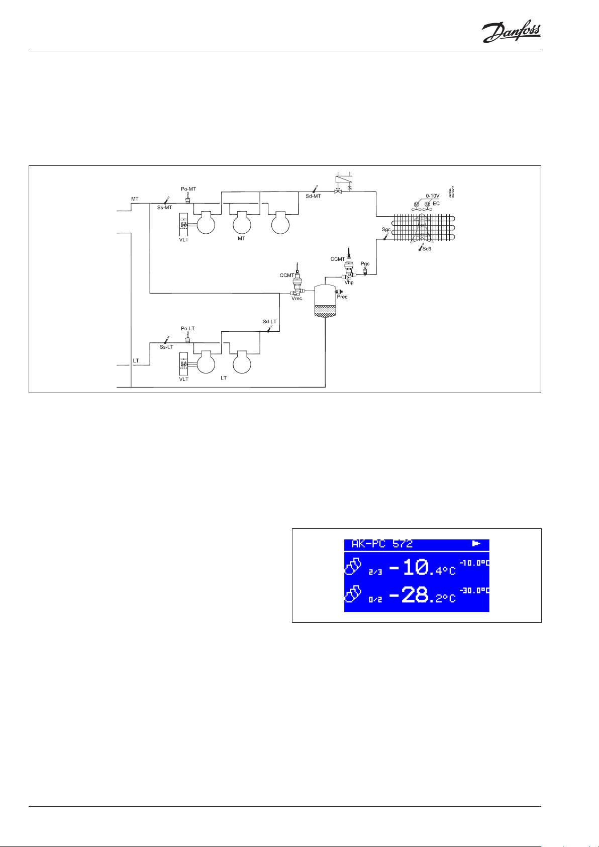
Application
The controller is used for capacity regulation of compressors
and gas cooler in small CO2 refrigeration applications.
As a minimum, control of a condensing unit can be performed
using one compressor unit, one gas cooler and one receiver.
A maximum of 3+2 compressors can be regulated.
Fx:
Advantages
• Energy savings via:
- Optimal control of CO
- Optimisation of suction pressure
- Night time increase
- Floating gas cooler reference
- Heat recovery
- Load limitation
• Simplified setting of the functions
The controller ensures that the different control settings are
adjusted in accordance with one another. Only basic settings are
required.
• Ongoing adjustment of control references
Newly developed algorithms adjust the problematic pressure
ratios in the CO2 controller.
Input and output
There are a limited number of available inputs and outputs so
most connections are intended for one specific function.
However, there a few options for AUX use:
• If only one or two compressor units are connected to the MT
circuit, there will be a DI input available. This could, for example,
be used as an alarm input.
• If the compressor used is not a Bitzer CRII, a solid state output
can be used for oil management.
• If heat recovery is not used, the AUX3 function can be used for an
alarm function.
2
Operation
The daily operation can be set up directly on the controller or
via an external display device.
During set-up, the display images will be adjusted so that only
the relevant images are opened for additional setting and
end-user operation.
The operation is password protected, and three levels of
access can be granted.
The controller contains several languages. Select the preferred
language at start-up.
Data communication
The controller has built-in modbus data communication, and it
can be connected to an AK-SM 800 type system device.
In order to control the high pressure valve and receiver pressure
valve, two valve driver modules, type EXD 316, must be connected.
The overview of connections can be seen on page 22.
2 User Guide RS8KH202 © Danfoss 2019-03 AK-PC 572
Suction Group
Compressor types
The following types of compressors can be used for regulation:
• Single-step compressors (one can be speed-regulated)
• Bitzer CRII compressor with two unloaders (4-cylinders). MT only.
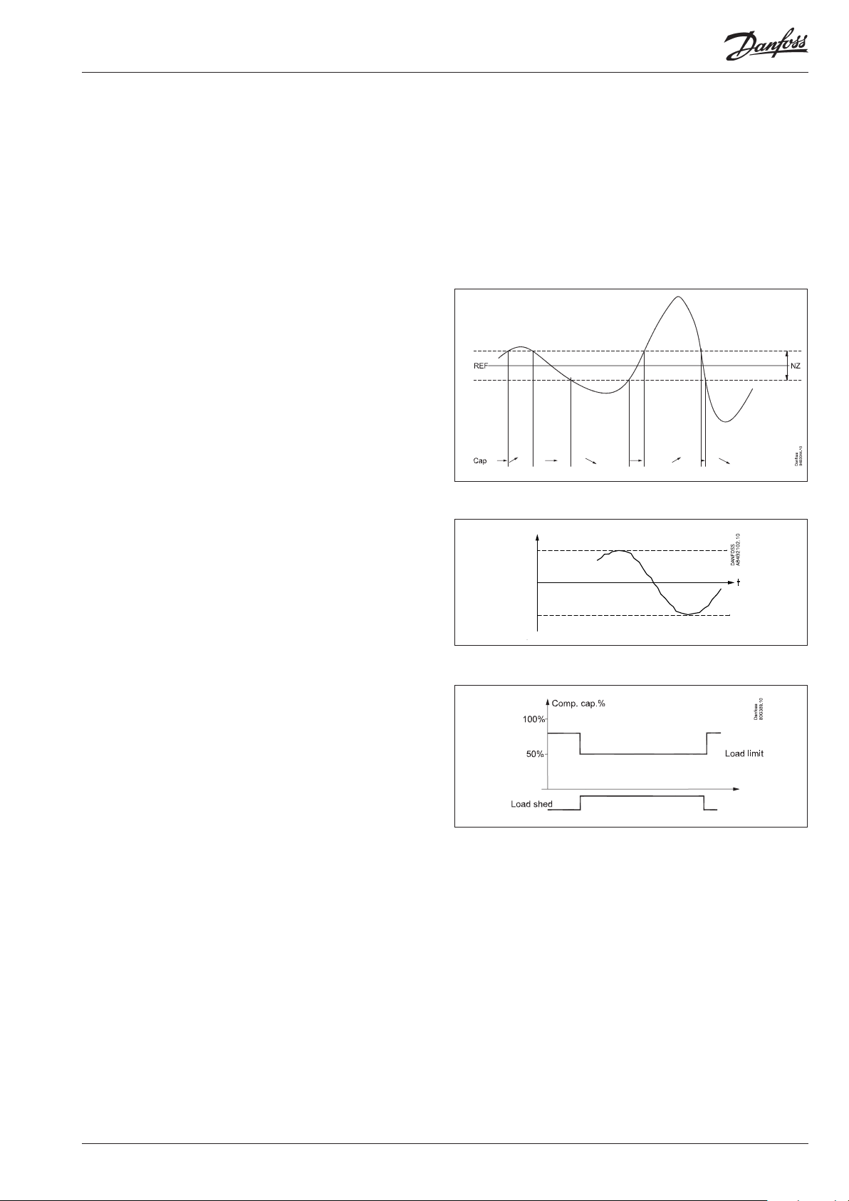
Capacity regulation
The cut-in capacity is controlled by signals from the connected
pressure transmitter and the actual reference.
In the absence of any reference there is a neutral zone of up to 5 K.
– When the pressure is higher than the “reference + a half neutral
zone”, cut-in of the next compressor (arrow up) is permitted.
– When the pressure is lower than the “reference - a half neutral
zone”, cut-out of a compressor (arrow down) is permitted.
– When the pressure is within the neutral zone, the process
will continue with the currently activated compressors.
This is always controlled using the "Best fit" connection pattern.
The reference
The controller will be set based on a fixed reference point.
Based on the configured reference, the controller will permit an
offset of up to +/- 8K depending on the other control parameters.
For example
- Night-time increase. Fixed 5 K (on the MT circuit only)
- Po optimisation (on the MT circuit only)
Po ref.
8 K
8 K
Load shedding
The function is activated from the system unit.
When the load shedding function is activated, the maximum
permissible compressor capacity will be limited to 50% of
maximum on both MT- and LT circuits.
In this way, the total electrical load in the store is limited.
Control parameters
To make it easier to start up the system, we have grouped the control parameters into a number of experience-based values. These
values have been combined in a setting called "Easy-settings".
Here you can choose between a set of control settings applicable
to a slow to rapidly reacting system.
The factory setting is medium.
Oil management
If the DO6 output is in use by a CRII, oil management cannot take
place. If the output is available, the controller can pulse oil into the
MT circuit. The time between the pulses can be configured using a
timer function or using a signal from a level switch.
AK-PC 572 User Guide RS8KH202 © Danfoss 2019-03 3
Liquid injection in the MT suction line
This function is possible only if there is an available DO output.
The function opens for liquid when:
• The suction temperature is too high
• The pressurised gas temperature is too high
• Liquid inlet to the compressor must be prevented.
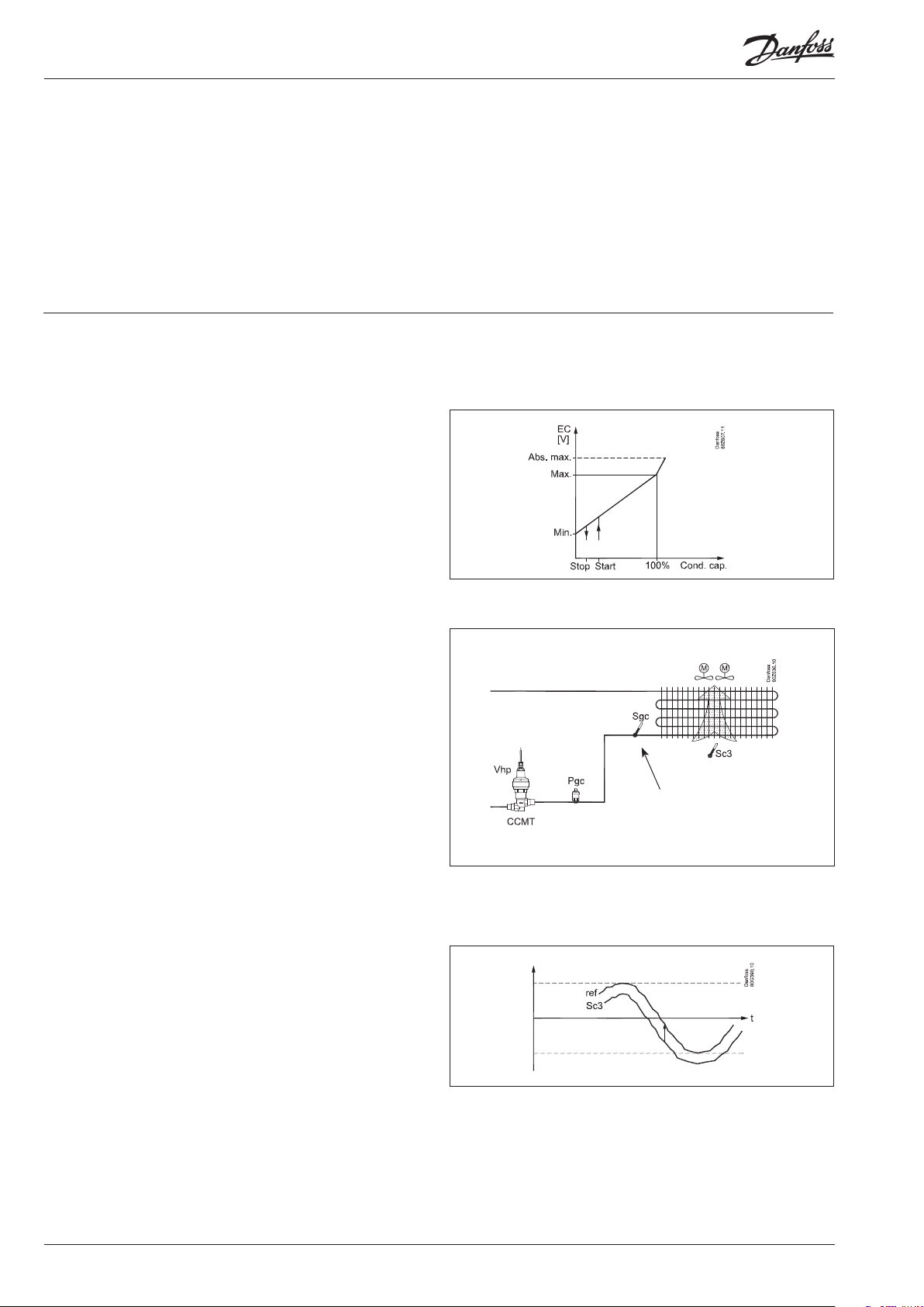
Gas cooler
Fan control
The fans must be speed controlled by the controller's analog
output.
EC motors can receive the 0-10 V signal directly.
During night operation, the noise level of the fans can be kept
down. This is done by limiting the voltage and thus the speed.
The limitation is bypassed if safety function Sd max. start to
function.
De-super heater
This function is possible only if there is an available DO output.
This function activates a fan so that the pressurised gas temperature in the LT circuit can be lowered:
• The fan stops when the outdoor temperature is low
• The fan stops when the MT suction gas is too low
Regulation
The controller regulates the pressure in the gas cooler (condenser)
so that the system achieves the optimal COP.
The controller will always optimise to a subcritical state.
The pressure in the gas cooler is controlled by the valve Vhp.
Regulation must have inputs from both a pressure transmitter Pgc
and a temperature sensor Sgc. Both must be fitted in the outlet
immediately after the gas cooler.
The valve is an CCMT valve, which has been specially developed
for the pressure conditions that exist in a transcritical CO2 system.
The valve's degree of opening can be restricted both at the
closing point and in the entire open point.
Maximum COP control
During normal operation without override, the controller will
maintain the optimum pressure in the transcritical area.
Reference
It is controlled using variable references.
An outdoor temperature sensor, Sc3, must be installed.
The sensor must be positioned so that it registers the correct outdoor temperature. In other words, it must be shielded from direct
sunlight and located near the airway of the condenser.
Under normal operations it will be controlled using a fixed temperature reference of 3 k above the outdoor temperature.
The pressure reference will be the configured value for the subcooling when adjusting in the sub-critical range, and will be adjusted based on optimal COP when adjusting in the trans-critical
range.
Important
This sensor must be placed
immediately at the gas
cooler outlet.
The reference value will be user-configured during heat recovery.
4 User Guide RS8KH202 © Danfoss 2019-03 AK-PC 572
Heat recovery
A digital input can be received.
When the signal is received, the reference for the gas cooler will
be raised to the configured value.
When the temperature of the heat recovery has been reached
and the DI signal disappears, the reference will drop once again,
though it will do so over the course of a few minutes to prevent
abrupt changes in the reference.
A potential relay outlet can be connected to heat recovery. The
potential relay is activated when the controller allows for heat
recovery.
Cooling will always have a higher priority than heat recovery. If
this higher priority occurs, the potential relay will be deactivated
and the reference for heat recovery will be removed from the
controller.
The cooling reference is now used for regulation until the tempe-
ratures and pressure allow for heat recovery to resume.
During heat recovery, regulation can be carried out in accordance
with:
• Max. COP - Most energy-optimal.
• Max. HR - The highest achievable temperature.
Pgc ref
DI
Warning
Remember that the controller controls the gas pressure. If the
regulation is stopped by the internal or external main switch, this
control will stop as well.
Risk of loss of charge.
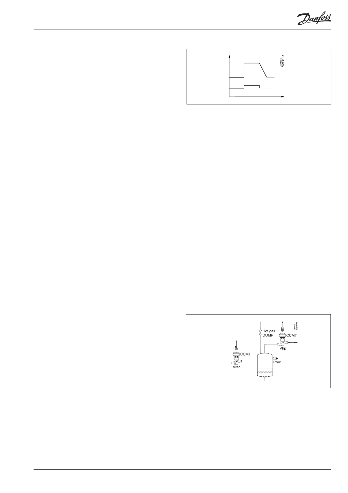
Receiver control
The receiver pressure can be controlled so that it is kept at the
desired reference point. This reference point is fixed at 6 bar above
the reference point for Po-MT. This control requires the installation of an receiver valve Vrec and a pressure transmitter.
Hot gas dump
This function is possible only if there is an available DO output
This function allows for hot gas to be passed to the receiver if the
pressure approaches Po-MT.
Hot gas will be shut off again when the pressure returns above the
desired level.
AK-PC 572 User Guide RS8KH202 © Danfoss 2019-03 5

AUX functions and limitations
AUX1-DI and -DO
This function shares an input and output with an MT compressor
3.
AUX1 is possible only if regulating using one or two compressors
on the MT.
AUX1-DI can then be used as an alarm input.
AUX1-DO can then be used for liquid injection, DE-SH or hot gas
dumping.
DO6
The output is a solid state output and reserved for a CRII. If not
regulating using a CRII, DO6 can be used to control an oil valve.
Oil management.
Oil management will share an output with a CRII compressor.
Oil management can take place only if not regulating with a CRII.
Oil management can be performed with a timer function or with
a level signal from an oil receiver. This signal can only be included
in the "OIL" input. If the input is not used for OIL it will be available
and called AUX2-DI. It can then be used as an alarm input.
AUX2-DO
The potential relay output can be freely used for liquid injection,
DE-SH or hot gas dumping.
Survey
Connection "572"
1. priority
MT3 x x
CRII x
Heat recovery x (x)
2. priority
Oil No
CRII
Fan error Max. 1 x x x
Alarm text Max. 1 x x x
Liquid
injection
DE superheat x x x
Hotgas dump x x x
DI3
"572"
"572"
DO3
x x x
HP DIHP DORec DIRec
DO6
x (x)
DO
AUX3-DI
This function shares an input with the heat recovery function.
AUX3-DI is possible only if heat recovery is not used.
AUX3-DI can then be used as an alarm input.
AUX3-DO
This function is reserved for heat recovery but only if a potential
relay output is also required to be activated when heat recovery is
regulated.
If the output is not used for heat recovery, it can be used for liquid
injection, DE-SH or hot gas dumping.
AUX_-DI as an alarm input
There are two alarm options:
• A "Fan error" that will be shown in the display and in the system
unit if it occurs.
• A text alarm that will be shown in the display and in the system
unit if it occurs.
6 User Guide RS8KH202 © Danfoss 2019-03 AK-PC 572

Safety functions
Control optimisation
The controller continually registers the different pressures in the
system.
The pressures are automatically adjusted for the most energyoptimal pressure.
If the pressure approaches a threshold value, the controller will
adjust the different references to maintain control.
Min./max. suction pressure Po
The suction pressure is recorded continuously.
If the measured value falls below the set minimum limit,
the compressors will immediately cut out.
If it exceeds the max. value, an alarm will be generated once
the time delay has elapsed.
LP switch
On/off signal on a DI input
If a signal is received, all compressors will immediately be stopped.
HP switch
On/off signal on a DI input
If a signal is received, all compressors will immediately be stopped.
Fan capacity will increase depending on how much the
Pgc measurement exceeds the reference.
Sensor failure
If lack of signal from one of the connected temperature sensors or
pressure transmitters is registered an alarm will be given.
• In the event of a Po error, regulation will continue with a set
capacity in daytime operation (e.g. 50%), and a set capacity in
night operation (e.g. 25%), but with a minimum of one step.
• In the event of a Pgc error, the fan capacity that corresponds
to how much compressor capacity is connected will cut in.
Compressor regulation will remain normal.
• When there is an error on the Sd sensor the safety monitoring of
the discharge gas temperature will be discontinued.
• When there is an error on the Ss sensor the monitoring of the
superheat on the suction line will be discontinued.
• In the event of an error on the outdoor temperature sensor,
Sc3, 35°C will be used as a reference.
NB: A faulty sensor must be OK within 10 minutes before a sensor
alarm is cancelled.
A sensor alarm can be reset manually by pushing the
"X-button" for 2 seconds when the alarm is shown in the
display "Active alarms".
Fan error alarm
On/off signal on a DI input. Possible only if the input is not used
for its intended purpose.
If the signal is received, an alarm is given.
Min./max superheating via Ss and Po measurement
Temperature sensor on an AI input.
If superheating is higher or lower than the set limits, an alarm
will be generated once the time delay has elapsed.
Max. discharge gas temperature Sd
Temperature sensor on an AI input.
There is an Sd for the MT group and an Sd for the LT group.
If the temperature nears the set max. temperature, the capacity of
the compressor will be reduced
The compressors will be stopped if the temperature nears
the set max. temperature value.
Liquid injection in the MT suction line
This function is configured in the AUX_DO output.
There are no configuration values. The controller determines when
liquid injection is required.
General DI alarm
On/off signal on a DI input. Possible only if the input is not used
for its intended purpose.
The controller contains one general alarm input, to which alarm
text and delay times can be connected.
Alarm and text will appear when the delay time has elapsed.
Info
In normal operating conditions, the temperature at Sd will be
between 60 and 70°C - depending on whether it is winter or
summer.
If the "Heat reclaim" function is to raise the condensing pressure,
the temperature may increase to 90° or higher.
The Sc3 sensor should be positioned so that it measures the air
intake temperature for the gas cooler. If it measures a temperature
that is too high, the system's COP will become impaired.
The Sgc signal must be stable. If this cannot be done using a surface sensor, it may be necessary to use an immersion tube sensor.
If the power supply to AK-PC 572 or the high pressure valve Vhp
fails, the system cannot be controlled. We recommend installing
an emergency supply (UPS) for both the controller and the valve
to avoid faults. A relay in the UPS should be incorporated into the
controllers safety circuit so that it can restart safely.
AK-PC 572 User Guide RS8KH202 © Danfoss 2019-03 7
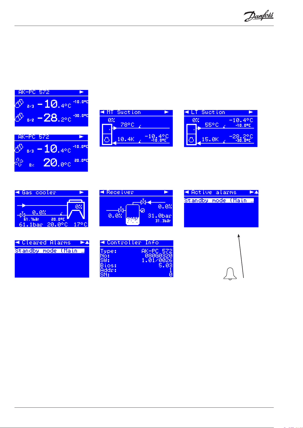
Display overview
End-user overview
The images in this daily user interface will depend on how the set-up is made. They will illustrate what is regulated.
Click on the "Right Arrow" to view e.g. the following images:
Booster + HP
MT + HP
When an alarm is sent from the controller, you must advance to this
display to see the alarm text. Then
click on the alarm text to view the
details relating to the alarm.
8 User Guide RS8KH202 © Danfoss 2019-03 AK-PC 572
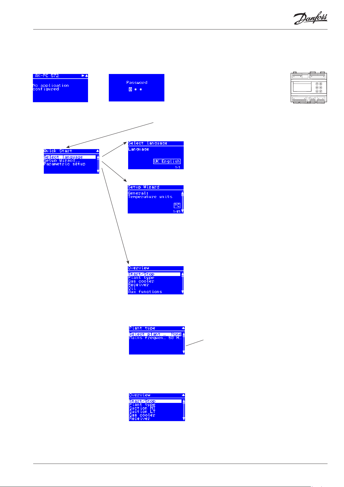
Set-up overview
There are 2 ways in which the controller can be set up. Select the one that is easiest for you: either “Wizard” or a review of
“all parameters”.
Start screen upon delivery
Operating principles
1. Select position using arrow keys
2. Select using “Enter”
3. Use the “X” to return
Hold “Enter” down
for 2 seconds to come to
password entry
Select a set-up method. End
by pressing “Enter”
The default password upon
delivery is 300. Use the arrow
keys to set the password. End
by pressing “Enter”
Language
Choose from one of the
possible languages
Wizard
Here you will be led through a series of settings, after
which the controller will be ready for start.
Image 1 of 27 is displayed here.
Parameter settings
Here is the start image for
the possible settings.
Main Menu
The first setting is the
Plant type
The following options are available here:
• Booster + HP
• MT + LT
When the Plant type has
been selected, it will allow several settings to be
made.
For example:
Continue to the next
menus.
All settings are explained
on the pages that follow.
AK-PC 572 User Guide RS8KH202 © Danfoss 2019-03 9

Menu
Start/stop
Plant type
Suction MT
Main switch
Main switch
Start and stop regulating here.
The configuration settings will require that regulating is stopped.
If you try to enter a configuration setting when regulating has started, the controller will
ask if regulating should be stopped.
When all settings have been made and the main switch is set to “ON”, the controller will
enable the display of the various measurements. Regulation will start. (One external main
switch must be “ON” before regulating starts.)
Extern Main swich
Status on External main switch
It is possible to connect an external switch which can be used to start and stop regulating.
Both the internal and external main switch must be ON before regulating starts.
If the external cutout is omitted, the dedicated input must be shorted.
Select Plant type Plant settings:
The following must be regulated:
• Booster + HP
• MT + HP
Mains frequency Frequency
Set the net frequency
Control status MT Regulation status
Control status Read the status of the functions in the control circuit here
Reference The total regulation reference can be read here
ToMT temperature The measured PoMT pressure converted to temperature can be read here
PoMT Pressure The measured pressure for the PoMT pressure transmitter can be read here
Requested capacity Here the preferred connected capacity can be read as a % of total capacity
Running capacity Here the connected capacity can be read as a % of total capacity
No. of running comp. The number of compressors in operation can be read here
MC PoMT offset The size of a reference displacement on PoMT required from the system unit
(suction pressure optimisation function) can be read here
SdMT discharge
The measured discharge temperature can be read here
temp.
SsMT Suction gas
The measured suction gas temperature can be read here
temp.
Superheat MT The actual superheat can be read here
Day / Night status The status of the day/night function can be read here
Load shed The status of the load shed function can be read here
HP Safety switch The status of the security circuit can be read here
Injection ON MT The status of the injection ON signal sent to the evaporator controllers can be read here
Liq. inj. suction line
The status of hte liquid injection in the suction line can be read here
MC Load Shedding The status of the load shed signal received from the system device can be read here
MC Night Setback The status of the night increase signal received from the system device can be read here
Control settings Regulation settings
Control mode Regulation type
The regulation is normally set to “Auto”, but it can be changed to “Off” or “Manual”.
Manual capacity When setting to “Manual”, a forced capacity setting can subsequently be entered in %.
Setpoint Enter the set point for the regulation (regulation reference = set point + different offsets) here
An offset can originate from a night increase signal or from an override function on the
system device.
PI control selection Set how quickly the PI regulation must react here: 1 = slowly, 10 = very quickly.
SW: 1.0x
On / Off
Fac: None
50 Hz / 60 Hz
Fac: 50 Hz
MAN / OFF / AUTO
Fac: AUTO
Min: 0 %
Max: 100%
Min: -55°C
Max: 20°C
Fab: -10°C
Min: 1
Max: 10
Fab: 5
10 User Guide RS8KH202 © Danfoss 2019-03 AK-PC 572

Pump down
Pump down function
To avoid too many compressor starts/stops with low load, it is possible to define a pump down
function in which the compressors are stopped when the suction pressure falls to "Pump down
limit Po".
This limit has been set at 6 K below the reference point for Po.
Injection OFF delay Delay of the forced closing of expansion valves, if the controller calls for cut in of compres-
sors, but the compressors are in a locked situation and therefore cannot start.
Configuration
Configuration
Compressor mode Set the type of compressor to be used for regulation:
• Multi + Single:***) First compressor has unloaders. The remaining ones are one-step units
• CRII4+Single **
)
First compressor is CRII4 compressor. The remaining ones are
one-step units
(In the event that CRII is selected it will not be possible to select oil management)
• Single-step only: All are one-step compressors
• None:
No. of compressors Set the number of compressors on the suction circuit MT
This is a total amount.
If regulating with two compressors only, DI3 and DO3 can be used for the AUX1 function.
Lead comp. 1 size Set the nominal compressor capacity for the first compressor (it is defined under
“Compressor mode”)
Comp. 2 size Set the nominal compressor capacity for compressor 2
Comp. 3 size Set the nominal compressor capacity for compressor 3
VSD Min. speed ***: For speed
Min. speed at which the compressor will cut out
VSD Start speed
***: For speed
Minimum speed at which the compressor will start (must be set to a higher value than
“VSD Min. speed”)
VSD Max speed
***: For speed
Highest permitted speed for compressor
CRII Period time **: For CRII
Set the period time for the unloader valve (on time + off time)
Comp1 min Cap **: For CRII
Configure the minimum capacity at which the compressor will stop
Comp1 start Cap **: For CRII
Configure the capacity at which the compressor will stop
Compressor timers Compressor timers
Lead comp.1 Restart Min. period of time for re-starting the first compressor.
Set the forced on+Off-time before it can be switched on again. The setting is to prevent incorrect operation.
To prevent a compressor breakdown, the setting must be made in accordance with the
requirements of the compressor supplier.
Comp. Restart Min. period of time for restarting remaining compressors
Set the forced On+Off-time before it can be switched on again. The setting is to prevent
incorrect operation.
Yes /No
Fac: No
Min: 0 s
Max: 300 s
Fac: 120 s
DO-demand
Fac:
Speed+single
DI + DO-demand
Min: 1
Max: 3
Fac: 3
Min: 1 m3h
Max: 20 m3h
Fac: 1 m3h
Min: 1 m3h
Max: 20 m3h
Fac: 1 m3h
Min: 1 m3h
Max: 20 m3h
Fac: 1 m3h
Min: 10 Hz
Max: 60 Hz
Fac: 30 Hz
Min: 20 Hz
Max: 60 Hz
Fac: 45 Hz
Min: 40 Hz
Max: 120 Hz
Fac: 60 Hz
Min: 10 s
Max: 60 s
Fac: 20 s
Min: 10 %
Max: 50 %
Fac: 10 %
Min: 10 %
Max: 100 %
Fac: 30 %
Min: 1 min.
Max: 60 min
Fac: 5 min
Min: 1 min.
Max: 60 min
Fac: 5 min
AK-PC 572 User Guide RS8KH202 © Danfoss 2019-03 11

Suction LT
Gas cooler
Compressor status Compressor status
Comp. 1 status Read the operating status for compressor 1 here. The following information may appear:
Alarm - Alarm situation
Main Sw. off - Compressor is stopped
Manual ctrl. - Compressor is cut out on safety input (DI safety input)
High Sd temp. - Stopped due to high Sd temperature
Ready - Compressor is ready to start
OFF timer - Compressor is waiting for Min OFF timer to expire
Min. ON timer - Compressor is waiting for Min ON timer to expire
Running - Compressor is running
Disabled - Compressor has been taken out of operation (compressor service)
Comp. 2.... The same function for the remaining compressors
Compressor capacity Compressor capacity
Comp. 1 cap. Read the connected capacity of the compressor (0-100%) here
Comp. 2...... The same function for the remaining compressors
Compressor runhours Compressor run hours
Reset runtime/cycles Reset all of the hour counters and start counters for the subsequent compressors here.
Comp.1 Runtime L Read the total operating time of the compressor (in hours) here
Comp.2..... The same function for the remaining compressors
Compressor cycles Compressor cycles
Comp.1 Cycle total Read the number of times the compressor has been started here
Komp.2..... The same function for the remaining compressors
Compressor service Compressor service
Comp.1 out of service The compressor can be taken out of operation, so that the controller regulates without this
compressor.
No = Normal regulation
Yes = Regulating is carried out without this compressor, and no alarms are generated by it.
Comp.2..... The same function for the remaining compressors
Suction group LT . Please see descriptions under suction group MT.
(In suction group LT it is not possible to use: Bitzer CRII, Po optimisation and night-time reduction).
Control status Regulation status
Control status Here you can read the status of the condenser circuit, e.g.:
• Main Sw. off - Main switch = OFF
• Normal - Controller working as expected
• Emergency – Emergency Controls
• Manual ctrl - Capacity control is set in manual control mode
Pgc The current value of the regulation sensor can be read here
Sgc The current value of the regulation sensor can be read here
Pgc Reference The total regulation reference can be read here
Sgc Reference The total regulation reference can be read here
Vhp OD Here you can see the opening degree of the Vhp valve
Fan running capacity
Fan requested
Here the connected capacity can be read as a % of total capacity
Here the preferred connected capacity can be read as a % of total capacity
capacity
Sc3 air on cond. The measured outdoor temperature with sensor Sc3 can be read here
Heat recovery status Here the status of the heat recovery function can be read
HP safety switch The status of the HP safety switch can be read here
Day / night status Here you can see whether the controller is in Day or Night mode
Control settings Control settings
Vhp control mode Regulation type
The regulation is normally set to “Auto”, but it can be changed to “Manual”.
Vhp manual capacity When setting to “Manual”, capacity can then be forced set in %.
Yes /No
Fac: No
MAN / AUTO
Fac: AUTO
Min: 0 %
Max: 100%
12 User Guide RS8KH202 © Danfoss 2019-03 AK-PC 572

Vhp Easy PI
Set how quickly the PI regulation must react here: 1 = slowly, 10 = very quickly.
(For setting 0 "User def." the special settings options will open. Kp, Tn. These options are only for
trained staff.)
Vhp Kp Amplification factor for PI regulation (can be viewed and configured only when the previous
menu has been set to "0"). If the Kp value is lowered, regulation runs more smoothly
Vhp Tn Integration time for PI regulation (see above)
If the Tn value is increased, regulation will run more smoothly
Vhp min OD Limitation of the valve's degree of closing
Averange OD Readout of the average opening degree of the valve
Fan control mode Regulation type
The regulation is normally set to “Auto”, but it can be changed to “Manual”.
Min: 0 (User def.)
Max: 10
Fac: 5
Min: 0,5
Max: 10
Fac: 2,0
Min: 30
Max: 300
Fac: 75
Min: 0%
Max: 15%
Fac: 0%
Min: 0%
Max: 100%
Fac: 35%
MAN / OFF / AUTO
Fac: AUTO
Fan manual capacity When setting to “Manual”, capacity can then be forced set in %.
Fan Easy PI
Set how quickly the PI regulation must react here: 1 = slowly, 10 = very quickly.
(For setting 0 "User def." the special settings options will open. Kp, Tn. These options are only for
trained staff.)
Fan Kp Amplification factor for PI regulation (can be viewed and configured only when the previous
menu has been set to "0")
If the Kp value is lowered, regulation runs more smoothly
Fan Tn Integration time for PI regulation (can be viewed and configured only when the previous
menu has been set to "0")
If the Tn value is increased, regulation will run more smoothly
dt subcool
Here you can set the desired sub-cooling
Heat recovery Define whether a heat recovery cycle should be started with a signal on a DI input here.
• No: No function
• DI only: A DI input is reserved. When a signal is registered, the heat recovery function refer-
ence will become active.
• DI and DO: Choose this setting if you are also activating a potential relay output (HR on the
receiver module).
Heat reclaim mode Here you configure the controller for when a signal is received for heat recovery.
You can choose between raising the temperature to achieve maximum heat recovery or
maintain temperature at the level with the highest efficiency.
Heat recovery SP Here you can set the reference that the controller will switch to when heat recovery is desi-
red.
Fan configuration Configuration of fans
EC Start
Here you can configure the controller capacity at which the fans will start.
(With a setting of 5% the fans will start when the desired controller capacity exceeds 5% of the
EC Min. setting)
EC Min.
Here you configure the lowest permitted speed for the fans in % (% of output signal)
If lower capacity is required, this minimum speed should be maintained all the way down to
0% capacity. At 0% capacity, the system stops completely.
EC Max.
Here you configure the fan speed in % when regulating at 100% capacity. (Typically 80% of the
output signal).
EC abs max Sgc
Here you configure the Sgc temperature at which the fan speed is raised to the absolute maximum (100% of the output signal)
Fan status Fan status
Fan speed Here a reading of the desired condenser fan capacity is provided in %
EC start/stop Fan operation status can be read here
Reset runtime cycl.
EC Runtime total
EC Cycl. total
Here the two counters "run time" and "couplings" can be reset
Here you can see how many hours the fans have been operational for since the last reset
Here you can see how many fan starts there have been since the last reset
Min: 0 %
Max: 100%
Min: 0 (User def.)
Max: 10
Fac: 5
Min: 0,5
Max: 50
Fac: 10
Min: 10 s
Max: 900 s
Fac: 180 s
Min: 1,0 K
Max: 30,0 K
Fac: 4,0 K
Fac: No
High effect /
Max. recovery
Fac: High effect
Min: 70 bar
Max: 100 bar
Fac: 80 bar
Min: 0%
Max: 20%
Fac: 5%
Min: 0%
Max: 30%
Fac: 20%
Min: 30%
Max: 100%
Fac: 80%
Min: 20°C
Max: 60°C
Fac: 60°C
AK-PC 572 User Guide RS8KH202 © Danfoss 2019-03 13

Receiver
Rec. control status
Control status Here you can see the status of the receiver controller:
Prec Off / Idle / Emergency / Normal / Hot gas dump
Prec reference Here you can see the receiver pressure
Vrec OD Here you can see the reference point for the receiver pressure
Hot gas dump Here you can see the opening degree of the valve Vrec in %
Rec. control settings
Control mode
Vrec manual capacity
Prec max. Here the maximum receiver pressure can be configured
Easy PI select
Kp
Tn
Manual hot gas Here you can override the hot gas valve.
Oil Control
Control type Adjust whether oil management will be used.
Oil control status Here you can see the oil management status:
Oil cycle time Adjust the period between pulses. (Only if regulated with the "Timer only" setting)
Oil pulse duration Adjust the valve opening time for each pulse
Safety monitoring
PoMT Min. limit Safety limits for min. PoMT
PoMT Max. alarm Alarm limit for high PoMT
Superheat Min. MT Alarm limit for insufficient superheating
Superheat Max. MT Alarm limit for excess superheating
Receiver status
Here you can see the status of the valve for hot gas dumping
Controller type
The controller is normally set to "Auto" but can be changed to "Manual".
When setting to "Manual", capacity can then be forced set in %.
Set how quickly the PI regulation must react here: 1 = slowly, 10 = very quickly.
(For setting 0 "User def." the special settings options will open. Kp, Tn. These options are only for
trained staff.)
The reinforcement factor for the PI controller (can only be viewed and configured when the
previous menu has been set to "0")
If the Kp value is lowered, regulation runs more smoothly
Integration time for PI regulation (see above)
If the Tn value is increased, regulation will run more smoothly
(Only if hot gas dump is defined in the AUX section)
Limitation
It is only possible to use oil management if the solid state outputs (DO5 and DO6) are free.
If regulating using compressor type Bitzer CRII, the two outputs will be used by the compressor and oil management cannot be performed.
You can choose whether pulse controls run only with a timer function or whether pulse
controls are performed only when there is a signal from a level switch
None / Main switch off / Idle / Valve open / Delay before next pulse
If a low value is registered, all compressors will cut out
If a high value is registered, an alarm will be generated
If a higher value is registered during a load limitation, the load limitation will be cancelled
until Po has returned to the reference.
(Superheating is measured in the suction line by PoMT and SsMT.)
MAN / AUTO
Fac: AUTO
Min: 0 %
Max: 100%
Min: 34 bar
Max: 89 bar
Fac: 59 bar
Min: 0 (User def.)
Max: 10
Fac: 5
Min: 0,5
Max: 10
Fac: 2,0
Min: 30
Max: 300
Fac: 75
Auto
Man on
Man off
DO-demand
Non / Timer only /
Niveau
Fac: Non
Min: 180 s
Max: 1800 s
Fac: 300 s
Min: 1 s
Max: 30 s
Fac: 5 s
Min: -55°C
Max: 30°C
Fac: -40°C
Min: -30°C
Max: 30°C
Fac: 5°C
Min: 0 K
Max: 20 K
Fac: 4 K
Min: 20 K
Max: 80 K
Fac: 50 K
14 User Guide RS8KH202 © Danfoss 2019-03 AK-PC 572

SdMT Max. limit Safety limit for max. SdMT
PoLT Min. limit Same settings as for the MT group
PoLT Max. alarm
PoLT Max. delay
Superheat Min. LT
Superheat Max. LT
SdLT Max. limit
Pgc Max. Safety limit for max. Pgc
Safety restart time Delayed start-up following safety cut-out
Sensor alarm reset Reset alarm after sensor error
Aux. functions
Digital input
Digital output
DI AUX1
DI AUX2
DI AUX3
DI alam delay
DI alarm text
DO AUX1
DO AUX2
DO AUX3
At 10 K under the set value, the compressor capacity will be reduced, and the entire
condenser capacity will cut in.
If the threshold is exceeded, the entire compressor capacity will cut out.
If Pgc exceeds the value set here minus 3 K, the entire fan capacity will cut in,
and compressor capacity will be reduced by 1/3 for every 30 seconds.
If Pgc exceeds the threshold value, the entire compressor capacity will immediately cut out,
and an alarm will be generated when the delay time expires.
If a safety cut-out has occurred due to “Sd max. limit”, “Pgc max. limit” or “Po min. limit”,
the compressors must be kept stopped for a defined period of time. The amount of
time can be set here.
When a sensor error has occurred, an O.K. signal must be registered within a specified
number of minutes before the controller resets the alarm. The regulation will be resumed
as soon as the sensor signal is O.K.
If there are only two compressors in the MT circuit, the DI3 output will be available for AUX1.
The input can then be used for an optional function.
You can choose between the functions "Fan error" or "Alarm"
If level signals are not desired for oil management, the "DI on the high pressure module" input
will be available.
The input can then be used for an optional function.
You can choose between the functions "Fan error" or "Alarm"
If an "HR req" signal is not desired for use in heat recovery, the "DI on the receiver module" input
will be available.
The input can then be used for an optional function.
You can choose between the functions "Fan error" or "Alarm"
Delay time for a DI alarm
Here you can choose what text to display in the event of a DI alarm.
The text can be seen in the display and can also be sent to a system unit.
Choose between the following texts:
General Alarm, Low Pressure, High Pressure, High Temperature, Low Temperature, Oil Level, Oil
Temperature, Liquid Level, Leak Detection, Inverter Fault, Dry Cooler, Pump, Motor Protection
Comp, Brine Pressure.
Note: There is only one alarm available. The signal will be received in one of the three AUX
inputs
If there are three compressors in the MT circuit, the potential relay output DO3 will be used by
MT3.
If there are only two compressors in the MT circuit, the potential relay can be used by one of the
following functions: Liquid injection, DE-SH or hot gas dumping
Relay output in the high pressure module
You can choose between the following functions:
Liquid injection, DE-SH or hot gas dumping
Relay output in the receiver module
You can choose between the following functions:
Liquid injection, DE-SH or hot gas dumping
Min: 60°C
Max: 160°C
Fac: 140°C
Min: -1 bar
Max: 159 bar
Fac: 40 bar
Min: 0 min.
Max: 60 min.
Fac: 2 min.
Min: 1 min.
Max: 30 min.
Fac: 10 min.
D/-demand
DI-demand
DI-demand
Min: 0 min.
Max: 360 min.
Fac: 0 min.
DO-demand
DO-demand
DO-demand
AK-PC 572 User Guide RS8KH202 © Danfoss 2019-03 15

System
Display Select views on the display
Language Choose from the following languages:
Pressure units Pressure unit
Temperature units Temperature unit
Time format Time format
Screen saver time Screen saver time
User logout time Log-off time
Display contrast Adjust contrast
Password Access code
Password level 1
Password level 2
Password level 3
Real time clock Date and time
Network Network
Modbus Address Set the address of the controller here if it is connected to a system device via data communi-
Baudrate The system unit usually communicates with 38.4.
Serial mode The value must not be changed
EXD reset node id Here the EXD module addresses can be reset so that the main module can assign the correct
Reset to factory Return to factory settings
I/O Configuration
Most connections have been given in advance and cannot be changed. See the connection diagram.
English, German, French, Danish, Spanish, Italian, Portuguese, Dutch, Russian, Polish, Czech,
Turkish, Hungarian, Croatian, Serbian, Romanian
Select bar or PSIG
Select °C or °F.
Choose 12-hour or 24-hour format.
If no buttons have been pushed for a specific period of time, the light in the display will be
minimised.
The light level will be restored upon renewed activity.
If buttons have not been pressed within a specified period of time, the screen will return to
the overview display. Afterwards, the user will have to log on again.
If the time is changed, the new time will apply the next time the user logs in.
If you log out here without waiting for the time-out period to elapse, go to the overview
display and hold down the “X” button for 3 seconds.
The settings in the controller can be protected with three levels of access codes.
Level 1: End user settings, such as changing the weekly plan
Level 2: Adjusting installer level
Level 3: Configuration of system settings (configuration menu)
The access code is a number between 001 and 999.
Used by weekly plan and alarm function.
cation.
If it is changed in the system unit to for example, "SLV" mode (19.2), setting must also be
changed to 19.2 here in the controller.
addresses. The procedure is described on page 21.
If this function is set to “YES”, all settings will be returned to factory default settings, and the
alarm list will be cleared.
-
Fac: UK English
Bar / PSIG
Fac: bar
°C / °F
Fac: °C
12 / 24
Fac: 24 h
Min: 1 min.
Max: 60 min.
Fac: 1 min.
Min: 1 min.
Max: 60 min.
Fac: 2 min.
Min: 0
Max: 100
Fac: 30
Fac: 100
Fac: 200
Fac: 300
Year, month, date
Hours, minutes
-
Min: 0 1
Max: 120
Fac: 1
Fac: 384
Fac: 8E1
For digital outputs, define whether the function will be active for an activated or deactivated relay.
For digital inputs, define whether the function/alarm will be active for an interrupted or shut-off switch.
For analogue outputs, define whether the output signal should be 0-5 V or 0-10 V
For analogue inputs, define:
Temperature sensors:
Normally, the sensor type is a Pt1000 model.Calibration value (+/- 10°C)
Pressure sensors::
Signal type: 4-20mA, 1-5V or 10-90% ratiometric of 5 V supply voltage.
Minimum and maximum pressure range
Calibration value (+/- 5.0 bar)
Please note:
If a function has been connected to an input or output and is subsequently deselected in the configuration, the function
in question will be marked with an exclamation mark (!). In this case, you must either activate the function in the configuration, or deselect the function on the input or output in question.
16 User Guide RS8KH202 © Danfoss 2019-03 AK-PC 572

I/O Status
Digital output On/off outputs
Most outputs have been locked to a function. These are as follows:
1: MT compressor 1
2: MT compressor 2
3: MT compressor 3. If no MT3 compressor is connected, the output must be configured for
'None'. The output can then be used for an AUX1 function. The function can be configured in
the AUX menu.
4: External alarm unit
5: Solid state output. Reserved for a Bitzer CRII.
6: Solid state output. Reserved for a Bitzer CRII. If a Bitzer CRII is not connected, the output can
be used to manage an oil valve.
7: LT compressor 1
8: LT compressor 2
When the compressor is idle, there will be no voltage to the bypass valves. Voltage is connected
immediately before the compressor is started.
Digital input On/off inputs
Most inputs are locked to a function. These are as follows:
1: Signal from compressor 1 in the MT circuit. Once a signal is received, the compressor will
cut out. When monitoring an Sd temperature in a Bitzer CRII, the temperature signal must be
registered by an external thermostat that will then issue an on/off signal via the input.
2: Signal from compressor 2 in the MT circuit. Once a signal is received, the compressor will cut
out.
3: Signal from compressor 3 in the MT circuit. Once a signal is received, the compressor will cut
out. If not regulating with an MT3 compressor, the input can be used for an AUX1 function.
4: Signal from external main switch. Regulation starts when a signal is received.
5: Signal from the high pressure switch in the MT circuit. Once a signal is received, the circuit will
cut out.
6: Signal from the high pressure switch in the LT circuit. Once a signal is received, the circuit will
cut out.
7: Signal from compressor 1 in the LT circuit. Once a signal is received, the compressor will cut
out.
8: Signal from compressor 2 in the LT circuit. Once a signal is received, the compressor will cut
out.
The signal must be defined for each input. Should the function take effect when the input is Off
or when it is On
Analog output 0-10 V outputs
The outputs have been locked to the following functions:
1: Signal to the fans on the gas cooler
2: Not used
3: Signal for the speed controls in compressor 1 in the MT circuit
4: Signal for the speed controls in compressor 1 in the LT circuit
Analog input Analogue inputs
The outputs have been locked to the following functions:
1: Pressure transmitter PoMT
2: Pressure transmitter PoLT
3: Pressure transmitter Pgc
4: Pressure transmitter Prec
5: Temperature sensor SsMT
6: Temperature sensor SdMT
7: Temperature sensor Sgc
8: Temperature sensor Sc3
Stepper outputs
Here you can set the valve type.
Choose between the following types: CCM10...40, CCMT2....42, CTR20, ETS6...400.
Choose user-defined if there is a different type of valve. All valve data must then be configured
directly in the valve module. The control unit MMIMYK can be used.
Digital output
1:
Status of on/off outputs
Here you can see if the function is on or off.
.
8:
Digital input
1:
Status of on/off inputs
Here you can see the status of the function/alarm.
.
8:
Analog output
1:
Status of analogue outputs
Here you can see the size of the output signals as a % of max. signal.
3:
4:
On
Off
On
Off
Pressure signal:
Ratiometric
Temperature signal:
Pt 1000 ohm
Fac: CCMT-2
AK-PC 572 User Guide RS8KH202 © Danfoss 2019-03 17

Analog input
1:
.
8:
Expansion module
Vhp OD
Vrec OD
Ss-LT
Sd-LT
Oil / Aux 2 DI
HR / Aux3 DI
Aux 2 DO
HR / Aux 3 DO
HP SW version
Rec. SW version
I/O Manual Control
Digital output Manual control of a relay output
Analog output Manual control of analogue output
Expansion modules
Alarm priorities
General
Standby mode:
Sensor error:
Output in MANUAL:
Suction group MT
Low pressure:
High pressure:
Superheat
High Sd temperature
Compressor safety:
Suction group LT
Low pressure:
High pressure:
Superheat
High Sd temperature
Compressor safety:
HP
Fan safety:
HP control:
Status of analogue inputs
Here you can see pressure and temperature values received by the controller.
The values include calibration
Status of the EXD modules
Here you can see the actual opening degree of the valves, the temperatures in the LT circuit and
status of the inputs and outputs.
Under normal regulation, the function of the relay will be in “Auto”.
In the event of an override, the function will be switched to either “On” or “Off”.
Remember to switch to “Auto” when the override is to be completed.
During normal regulation, the function of the output will be “Auto”.
In the event of an override, the function must first be changed to “Manual”,
after which the output signal can be changed from 0-100%.
Remember to switch to “Auto” when the override is to be completed.
Manual control of a connection in the HP module and receiver module
During normal regulation, the function of the output will be "Auto".
In the event of an override, the function must first be changed to "Manual". The function can
then be set to the desired value.
Remember to switch to "Auto" when the override is to be completed.
Alarm priorities
The controller will issue an alarm notification if a specific incident occurs.
Each incident is set to indicate the importance of each alarm, but it is possible to modify the
importance of each. Choose from between the following priority levels:
Critical: Important alarms that require a high level of attention.
Severe: Alarms of intermediate importance
Normal: No important alarms
Disable: Alarms set to this priority level will be cancelled.
Factory setting for the alarm can be seen on page 19.
Auto / On / Off
Auto / Man
0-100%
Critical
Servere
Normal
Disable
18 User Guide RS8KH202 © Danfoss 2019-03 AK-PC 572

Alarm list
Alarm text Reason Priority
General alarms
Standby mode (Main sw. OFF) Alarm when control is stopped by internal or external Main Switch (DI input "Main Switch") Standby mode Normal
PoMT sensor error Pressure transmitter signal from PoMT defective
PoLT sensor error Pressure transmitter signal from PoLT defective
SsMT sensor error Temperature signal from SsMT suction gas temp. defective
SsLT sensor error Temperature signal from SsLT suction gas temp. defective
SdMT sensor error Temperature signal from SdMT discharge gas temp. Sd defective
SdLT sensor error Temperature signal from SdLT discharge gas temp. Sd defective
Pgc sensor error Pressure transmitter signal from Pgc defective
Prec sensor error Pressure transmitter signal from Prec defective
Sgc sensor error Temperature signal from Sgc defective
Sc3 sensor error Temperature signal from Sc3 defective
Output in manual mode An output is set in manual mode Output in MAN mode Normal
Suction MT alarms
PoMT Low suction pressure Minimum safety limit for suction pressure PoMT has been violated
LP safety switch cut out MT Low safety limit for external low pressure switch has been violated (DI input "LP switch MT")
PoMT High suction pressure High alarm limit for PoMT has been exceeded High pressure PoMT Critical
SsMT High superheat Superheat in suction line MT too high (measured by PoMT and SsMT)
SsMT Low superheat Superheat in suction line MT too low (measured by PoMT and SsMT)
SdMT High discharge temp. Safety prevention limit for SdMT discharge temperature has been exceeded (10K below safety limit) High disch. temp.SdMT Critical
Comp. 1MT High disch. temp Safety limit for discharge gas temperature has been exceeded
Comp 1-3MT safety cut out Compressor no. 1-3 MT has been cut out on general safety input (DI1, DI2, DI3)
Suction LT alarms
PoLT Low suction pressure Minimum sikkerhed grænse for sugetryk PoLT er blevet koblet ud Low pressure Po LT
LP safety switch cut out LT Low safety limit for external low pressure switch has been violated (DI input "LP switch LT")
PoLT High suction pressure High alarm limit for PoLT has been exceeded High pressure Po LT Critical
SsLT High superheat Superheat in suction line LT too high (measured by PoLT and SsLT)
SsLT Low superheat Superheat in suction line LT too low (measured by PoLT and SsLT)
SdLT High discharge temp. Safety prevention limit for SdLT discharge temperature has been exceeded (10K below safety limit) High disch. temp. S dLT Critical
Comp. 1LT High disch. temp Safety limit for discharge gas temperature has been exceeded
Comp 1-2LT safety cut out Compressor no. 1-2 LT has been cut out on general safety input (DI7, DI8)
Gas cooler alarms
Prec high alarm limit Alarm from the receiver High receiver pressure
High gas cooler pressure Pgc registrer a too high pressure High pressure Pc Critical
Common fan alarm A fan is reported as defective via the shared safety input (DI input "Fan Alarm") Fan Alarm Normal
Display alarm
EER31 See next page
setting
Sensor error Normal
Low pressure PoMT Normal
Superheat MT Normal
Compressor safety
cutout MT
Superheat LT Normal
Compressor safety
cutout LT
Default
Normal
Normal
Normal
value
Sensor alarms
Sensor alarms shut off automatically when the sensor has been O.K. for 10 minutes.
If you have corrected the sensor error and want to perform a manual, forced removal of the alarm, go to the “Alarm detail display”
Press and hold the “X” key for 2 seconds here.
AK-PC 572 User Guide RS8KH202 © Danfoss 2019-03 19

ERR31
Alarm on the external display - MMIGRS2
If the communication to the display is not carried out correctly, it will send
an “ERR31” error notification.
This may be caused by the displayed terminations not being installed, or
that there have been interruptions in data communication during the time
when the display retrieves the basic information from the controller.
Once the terminations have been inspected, you should then check the
software version of the external display. This is done by holding down
the Enter key and the X key for 5 seconds, until the Bios menu appears.
Next, press the X key and read off the software version in the bottom right
corner. The software version must be 1.13 or newer.
Once the display’s software version has been checked, check the display’s
settings as follows:
1. Hold the Enter key and the X key down for 5 seconds, until the Bios
menu appears.
2. Select the “MCX selection” menu
- Select the “Clear UI” line and press Enter
- Select the “Autodetect” line and press Enter
3. Press the X key to return to the Bios menu
4. Select the “COM selection” menu
- Select the “CAN” line and press Enter
5. Press the X key to return to the Bios menu
6. Select the “Start up mode” menu
- Select the “Remote application” line and press Enter
7. Press the X key to return to the Bios menu
8. Select the “CAN” menu
- Select the “Baudrate” line and check that it is 50K
- Select the “Node ID” line and check that it is 126
9. Press the X key to return to the Bios menu
10. Select the “Application” menu and press Enter.
The display will once again retrieve data from the controller. This process
will take about 5 minutes.
20 User Guide RS8KH202 © Danfoss 2019-03 AK-PC 572

Addresses of the valve modules
Important
Read the following before you connect the controller and the two
valve modules to the supply voltage.
Both valve modules are factory set with the same address.
In order to give each module the correct address, you must follow
this procedure:
1. On the two valve modules, remove the terminals with power
supply.
(The power supply is connected later, but in the correct order).
2. Connect the controller to the power supply
3. Check that the main switch is OFF
4. HP module: Mount the terminal with power supply
5. Wait 5 seconds
6. Receiver module: Mount the terminal with power supply.
Wait 5 seconds
All modules now have power supply and the two modules each
have their own address:
96 for the HP module
97 for the receiver module.
The addresses will only be used internally between the three
modules.
If anything has gone wrong, the two valve modules will have activated the function "EXD reset node ID" and the procedure must be
repeated.
Resetting incorrect addresses in the valve modules:
1. Connect all three modules to the power supply
2. Find the following setting on the controller module
"System"> "Network" > "EXD reset node id's"
3. Set the value to 20
4. Cut out the supply voltage to the valve modules
5. Repeat the earlier procedure.
If you wish to check the addresses of the two valve modules, you
should carry out the following:
1. Connect all modules to the power supply.
2. Immediately press on both the "X" and "Enter" buttons while the
controller is starting up.
3. Find the display "CAN SETTINGS" > "ACTIVE NODES"
The two 1-digits represent the addresses 96 and 97 respectively.
If you remove the connection to a valve module, the display of
the address will also disappear.
AK-PC 572 User Guide RS8KH202 © Danfoss 2019-03 21

Connections
Important!
Wait before connecting the power supply to the
modules!
32 A
6 A
(4)
6 A
(4)
In order to set the addresses 96 and 97, you must fol-
low the recommended procedure. See page 4.
Connection, lower level Connection, upper level
Warning!
+ must be connected
0.5 A
min. 50 mA
Ioff < 1.5 mA
0.5 A
min. 50 mA
Ioff < 1,5 mA
6 A
(4)
6 A
(4)
10 A
(3.5)
(3.5)
DO DO1 DO2 DO3 DO4 DO5 DO6 DO7 DO8 Σ 1-8
I Max. 10 A
U All 24 V or all 230 V a.c.
to +
(L to1to 1)
Warning
The supply voltage
of AI may not share
the signal with
other controllers.
Separate
supply
Electric noise
Signal cables for sensors, DI inputs, data communication
and display must be kept separate from high voltage
(230 V) electric cables:
- Use separate cable trays
- Keep a distance between high voltage and signal cables
of at least 10 cm
- Cables longer than 3 m at the DI input should be avoided
22 User Guide RS8KH202 © Danfoss 2019-03 AK-PC 572

MAIN MODULE
HIGH PRESSURE MODULE Address = 96
AO - Analog output, 3 pcs. AO1, AO3, AO4
Must be used if using frequency converters or EC motors.
Connect 24 V on N and L (separate power supply) Avoid earth
fault current.
- Use double-insulated transformer. The secondary side must
not be earthed.
Obtain 0-10 volts from terminals Com-AO1, N-AO3 and N-AO4.
PAY ATTENTION TO THE POLARITY of N.
(AO3 and AO4 are galvanically isolated. AO1 is not).
AI - Analog inputs,
Pressure transmitters, 4 pcs. AI1 - AI4
AKS 32R /
AKS 2050 /
MBS 8250
10-90% ratiometric
Temperature sensors, 4 pcs. AI5 - AI8
• Pt 1000 ohm, AKS 11 or AKS 21.
DI - Digital switch inputs, 8 pcs. DI1 - DI8
The connection may be a shut-down or interruption function.
Select what is to be activated during configuration.
(DI3 can be used as an AUX1 input, but only if regulated with 2
MT compressors).
Supply
24 V a.c. or d.c. Class II is required.
AK-PC 572 17 VA
EXD 316, HP 10 VA
EXD 316, rec 10 VA
Stepper valve, HP _ _VA
Stepper valve rec. _ _VA
Supply voltage to high pressure module
The power supply can be taken from the main module. It is
important that + is connected to +.
Battery
Ensure that the valve closes if there is no supply voltage.
Stepper valve
FX ventil type CCMT.
Connector:
5: WHITE
6: BLACK
7: RED
8: GREEN
Canbus
Data communication to the main module.
Sensor inputs
• Pt 1000 ohm, AKS 11 or AKS 21.
Contact input AUX 2
Signal from oil level,
or input for fan alarm or another alarm.
Relay output AUX 2
Activation of de-superheating or hot gas dump.
RECEIVER MODULE Address = 97
Supply voltage to high pressure module
The power supply can be taken from the main module. It is
important that + is connected to +.
Canbus
Communication to the high pressure module and to the receiver
module
"L" to "L" and "H" to "H"
A jumper must be connected between "H" and "R".
Terminate on the receiver module with a resistance of 120 ohm.
If mounting an external display, the termination must be done
differently. See next page.
Important!
In order to set the addresses 96 and 97, you must follow the recommended procedure. See next page.
Modbus
It is important that the installation of the data communication
cable is carried out correctly. See separate literature, no. RC8AC.
Remember termination at the termination points.
DO - Digital outputs, 8 pcs. DO1-DO8
DO5 and DO6 are solid state relays. The outputs are used for
connecting a Bitzer CRII. If a Bitzer CRII is not being connected,
output DO6 can be used for activation of an oil valve.
The relays are de-rated to the specified values.
The alarm relay will be driven under normal operation and
will drop in the event of alarms and insufficient voltage to the
controller.
(DO3 can be used as an AUX1 output, but only if regulated with
2 MT compressors).
Battery
Ensure that the valve closes if there is no supply voltage.
Stepper valve
FX valve type CCMT.
Connector:
5: WHITE
6: BLACK
7: RED
8: GREEN
Canbus
Data communication to the main module.
The section must be terminated using a 120 ohm resistor.
Contact input AUX 3
Signal from heat recovery,
or input for fan alarm or another alarm.
Relay output AUX 3
Activation of heat recovery,
or AUX 3 output for de-superheating or hot gas dump.
AK-PC 572 User Guide RS8KH202 © Danfoss 2019-03 23

External display
If an external display is connected, it must be connected to the
controller using a wire with a plug. See order.
Communication will take place via Canbus.
The Canbus termination must be moved away from the controller
and to the external display.
24 User Guide RS8KH202 © Danfoss 2019-03 AK-PC 572

Bitzer CRII
The pulse signal can also be used to control one of the CRII with 2 unloaders (4 cylinders version).
Compressor capacity can be controlled from 10 to 100% depending on the pulsation of the unloaders.
The unloaders are connected to DO5 and DO6.
Connect compressor relay to DO-MT1.
Unloader 2 follows unloader 1
but is offset a ½ period.
Separate Sd monitoring of CRII
If separate Sd monitoring is desired, the
temperature signal must be received from a
thermostat that subsequently issues an on/
off signal to the compressor safety circuit.
Unload 1
Unload 2
Injection off
The electronic expansion valves in the cooling appliances must be
closed when all the compressors are prevented from starting. As a
result, the evaporators will not be filled with fluid that can be led
to a compressor when the regulation process restarts.
This function can be achieved through data communication.
Alternatively, wiring must be created using the compressor relays.
When all compressors have been stopped, a signal must be issued to the evaporator controls that will subsequently close the
expansion valves.
AK-PC 572 User Guide RS8KH202 © Danfoss 2019-03 25

Data
Supply voltage
8 analog Input
8 digital input
Relay output
to capacity control
3 Voltage output
Display output For type MMIGRS2
Data communication
Environments
Enclosure IP 20
Weight 0.4 kg
Mounting DIN-rail
Connection terminals max. 2.5 mm2 multi core
Approvals
24 V a.c. +/-15% 50/60 Hz, 17 VA
24 V d.c. (20-60 V ), 17 VA
Pressure meauring:
10-90%, ratiometric
1-5 volt
4-20 mA
Temperature measurement
Pt 1000 ohm/0°C
From contact function
E.g. to:
Start/stop of regulation
Monitoring of safety circuits
General alarm function
4 pcs. SPDT (8A)
2 pcs. SPST (16A)
2 pcs. Solid State.
PWM for scroll unloadl
0-10 V d.c. Ri = 1kohm
Separate 24 V supply required
Modbus
for AK-SM 800
Canbus
for valve control modules and external display
-20 - 60°C, During operations
-40 - 70°C, During transport
20 - 80% Rh, not condensed
No shock influence / vibrations
EU Low Voltage Directive and EMC demands re
CE-marking complied with
LVD tested acc. EN 60730-1 and EN 60730-2-9
EMC-tested acc. EN61000-6-2 and 3
UL approval
AC-1: 6 A (ohmic)
AC-15: 4 A (inductive)
AC-1: 10 A (ohmic)
AC-15: 3,5 (inductive)
Imax. = 0.5A
Imin. = 50 mA.
Leakage<1.5 mA
Not short-circuit protected
Installation considerations
Accidental damage, poor installation, or site conditions, can give
rise to malfunctions of the control system, and ultimately lead to a
plant breakdown.
Every possible safeguard is incorporated into our products to
prevent this. However, a wrong installation, for example, could still
present problems. Electronic controls are no substitute for normal,
good engineering practice.
Danfoss will not be responsible for any goods, or plant components, damaged as a result of the above defects. It is the installer's
responsibility to check the installation thoroughly, and to fit the
necessary safety devices.
Special reference is made to the necessity of signals to the controller when the compressor is stopped and to the need of liquid
receivers before the compressors.
Your local Danfoss agent will be pleased to assist with further
advice, etc.
Pressure transmitter / temperature sensor
Kindly refer to catalogue RK0YG...
Mounting/dimensions
For DIN rail mounting only (IP 20)
26 User Guide RS8KH202 © Danfoss 2019-03 AK-PC 572

Ordering
Type Function Operation Supply voltage Code no.
AK-PC 572 Capacity controller With buttons and display 24 V 080G0320
EXD 316 Valve driver Operation from AK-PC 572 24 V 084B8042
MMIGRS2 Display unit With buttons and display - 080G0294
Wire for display unit,
L = 1.5 m, 1 pcs. 080G0075
L = 3 m, 1 pcs 080G0076
List of literature
Installation guide for extended operation RC8AC
Here you can see how a data communication connection to
ADAP-KOOL® Refrigeration control systems can be established.
AK-PC 572 User Guide RS8KH202 © Danfoss 2019-03 27

Danfoss påtager sig intet ansvar for mulige fejl i kataloger, brochurer og andet trykt materiale. Danfoss forbeholder sig ret til uden forudgående varsel at foretage ændringer i sine produkter, herunder i
produkter, som allerede er i ordre, såfremt dette kan ske uden at ændre allerede aftalte specifikationer.
Alle varemærker i dette materiale tilhører de respektive virksomheder. Danfoss og Danfoss-logoet er varemærker tilhørende Danfoss A/S. Alle rettigheder forbeholdes.
28 User Guide RS8KH202 © Danfoss 2019-03 AK-PC 572
ADAP-KOOL®
 Loading...