

Danfoss ADAP-KOOL AK-LM 340 User Manual
User Guide
Monitoring unit with
PI regulation
AK-LM 340
ADAP-KOOL® Refrigeration control systems

Contents
1. Introduction ............................................................................. 3
Application .................................................................................................. 3
Principles...................................................................................................... 4
2. Design of a controller ..............................................................7
Module survey ........................................................................................... 8
Common data for modules .................................................................10
Controller ...........................................................................................12
Extension module AK-XM 101A .................................................14
Extension module AK-XM 102A / AK-XM 102B .....................16
Extension module AK-XM 103A .................................................18
Extension module AK-XM 204A / AK-XM 204B .....................20
Extension module AK-XM 205A / AK-XM 205B .....................22
Extension module AK-XM 107A .................................................24
Extension module AK-XM 208C ................................................26
Extension module AK-OB 110 ....................................................28
Extension module AK-OB 101A..................................................29
Communication module AK-CM 102 .......................................30
Transformer module AK-PS 075 / 150 ...................................... 31
Preface to design ....................................................................................32
Functions ............................................................................................32
Connections ...................................................................................... 33
Limitations ......................................................................................... 33
Design of a monitoring ......................................................................... 34
Procedure: ..........................................................................................34
Sketch .................................................................................................. 34
Monitoring unit................................................................................35
Connections ...................................................................................... 36
Planning table .................................................................................. 37
Length .................................................................................................38
Linking of modules ......................................................................... 38
Determine the connection points ............................................39
Connection diagram ...................................................................... 40
Supply voltage ................................................................................. 41
Ordering ..................................................................................................... 42
3. Mounting and wiring .............................................................43
Mounting ................................................................................................... 44
Mounting of extension module on the basic module ....... 44
Wiring .......................................................................................................... 45
4. Conguration and operation ................................................47
Conguration ...........................................................................................49
Connect PC ........................................................................................ 49
Authorization .................................................................................... 50
Unlock the conguration of the controllers ..........................51
System setup ....................................................................................52
Set plant type ................................................................................... 53
Utility meters .................................................................................... 54
Thermostat functions .................................................................... 55
Two sensor thermostat .................................................................56
Dierence thermostat ...................................................................57
Temperature alarms ....................................................................... 58
Pressostat functions .......................................................................59
Dierence pressostat .....................................................................60
Pressure alarms ................................................................................61
Voltage controls ...............................................................................62
DI-alarms ............................................................................................ 63
General PI control ...........................................................................64
Conguration of inputs and outputs .......................................65
Set alarm priorities..........................................................................67
Check of settings.....................................................................................69
Lock conguration ..........................................................................73
Check conguration .......................................................................74
Check of connections .................................................................... 75
Installation in network .......................................................................... 76
First start of control ................................................................................77
Start the control ............................................................................... 78
Setup logs .......................................................................................... 79
5. Regulating functions .............................................................81
Monitoring functions ............................................................................ 82
Miscellaneous ..........................................................................................88
Alarm texts ................................................................................................ 90
2 RS8GV202 © Danfoss 2016-06 AK-LM 340
1. Introduction
Application
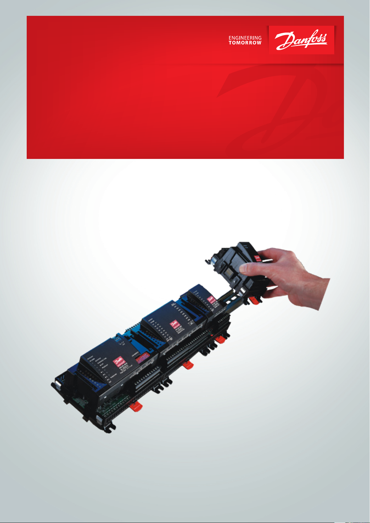
AK-LM 340 is a complete monitoring unit with the option of regulation functions via relay switches, stepper valves, PWM outputs
and voltage outputs.
The monitoring unit is used to detect temperature, pressure,
functions etc. in and around appliance cases and cold rooms for
commercial and industrial cooling.
The monitoring unit is equipped with data communication and is
operated via a PC.
Functions
Temperature
• Temperature detection
• Temperature monitoring with alarm function
• Extension of the alarm delay when a defrost signal (DI) is received
• Interruption of alarm monitoring when a switch signal (DI) is
received
• Temperature control with relay function
• Dierence thermostat with relay function
• Two-sensor thermostat with relay function
40
20
Pressure
• Pressure detection
• Pressure monitoring with alarm function
• Pressostat with relay function
• Dierence pressostat with relay function
Voltages of 0-10 V
• Voltage detection
• Voltage monitoring with alarm function
• Voltage monitoring with relay function
On/O signals
• Detection of switch signals
• Alarm function with delay + relay function, if applicable
• The switch signal can be inverted
• Hour counter for On time
• Counter for number of changes
Pulse signals
• Registration of electricity, water, gas, etc.
• Energy reading
Alarm relay
• Two alarm relays that are enabled on dierent alarm priorities
PI regulations
• 10 separate functions can be constructed.
20
20
8
The same reading can be used by several dierent
functions.
Up to 120 inputs and outputs are permitted.
Data communication
• Connection to system manager or gateway
• Monitoring and data collection
• Customised alarm texts
SW = 1.1x
AK-LM 340 RS8GV202 © Danfoss 2016-06 3
Principles
The great advantage of this series of controllers is that it can
be extended as the size of the plant is increased. It has been
developed for refrigeration control systems, but not for any
specic application – variation is created through the read-in
software and the way you choose to dene the connections.
It is the same modules that are used for each regulation and the
composition can be changed, as required. With these modules
(building blocks) it is possible to create a multitude of various
kinds of regulations. But it is you who must help adjusting the
regulation to the actual needs – these instructions will assist you
to nd your way through all the questions so that the regulation
can be dened and the connections made.
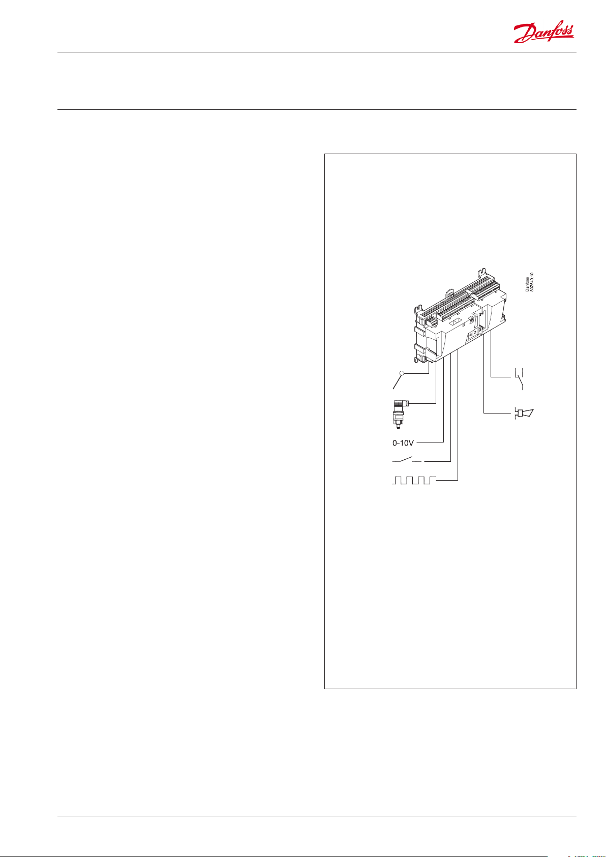
Controller
Top part
Advantages
• The controller’s size can “grow” as systems grow
• The software can be set for one or more regulations
• Several regulations with the same components
• Extension-friendly when systems requirements are changed
• Flexible concept:
- Controller series with common construction
- One principle – many regulation uses
- modules are selected for the actual connection requirements
- The same modules are used from regulation to regulation
Extension modules
Bottom part
The controller is the cornerstone of the regulation. The module has inputs and
outputs capable of handling small systems.
• The bottom part – and hence the terminals – are the same for all controller types.
• The top part contains the intelligence with software. This unit will vary according
to controller type. But it will always be supplied together with the bottom part.
• In addition to the software the top part is provided with connections for data
communication and address setting.
Examples
A regulation with few connections can
be performed with the controller module
alone
If the system grows and more functions have to be controlled, the regulation can be
extended.
With extra modules more signals can be received and more relays cut in and out
– how many of them – and which – is determined by the relevant application.
If there are many connections one or more
extension modules have to be mounted
4 RS8GV202 © Danfoss 2016-06 AK-LM 340
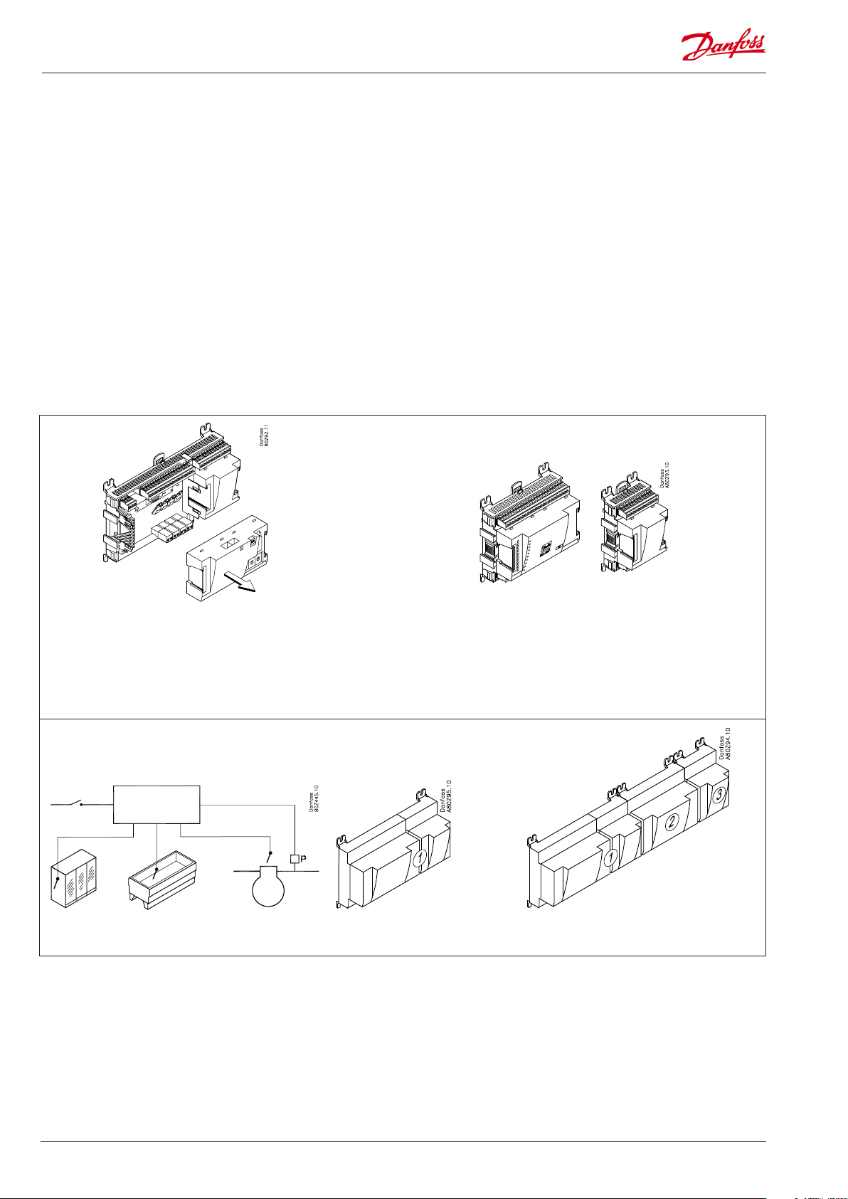
Direct connection
Setup and operation of an AK controller must be accomplished via
the “AK-Service Tool” software program.
The programme is installed on a PC, and setup and operation of
the various functions are carried out via the controller’s menu
displays.
Displays
The menu displays are dynamic, so that dierent settings in one
menu will result in dierent setting possibilities in other menus.
A simple application with few connections will give a setup with
few settings.
A corresponding application with many connections will give a
setup with many settings.
From the overview display there is access to further displays for
the compressor regulation and the condenser regulation.
At the bottom of the display there is access to a number of general
functions, such as “overview”, “manual operation”, “log function”,
“alarms”, and “service” (conguration).
Network linking
The controller can be linked up into a network together with other
controllers in an ADAP-KOOL® refrigeration control system.
After the setup operation can be performed at a distance with,
say, our software program type AKM.
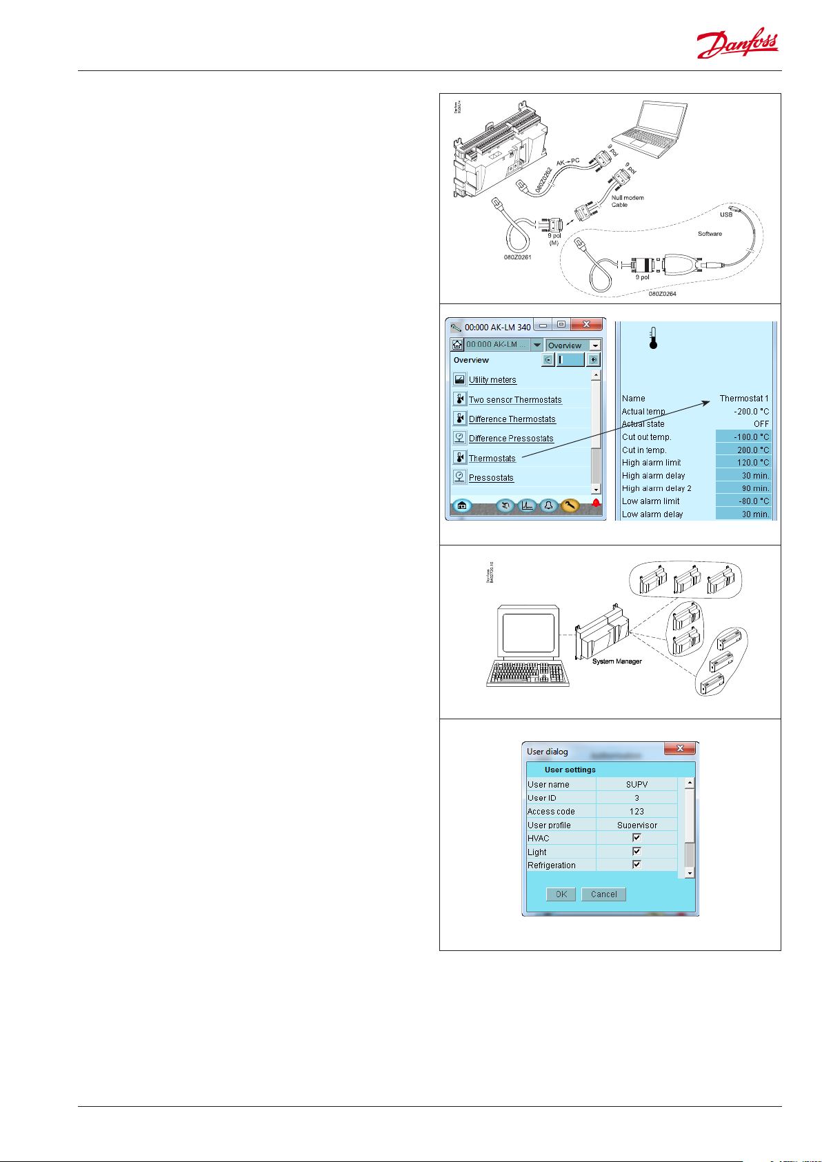
Users
The controller comes supplied with several languages, one of
which can be selected and employed by the user. If there are
several users, they may each have their choice of language. All
users must be assigned a user prole which either gives access to
full operation or gradually limits the operation to the lowest level
that only allows you “to see”.
AK-LM 340 RS8GV202 © Danfoss 2016-06 5
Light-emitting diodes
A number of light-emitting diodes makes it possible to follow the
signals that are received and transmitted by the controller.
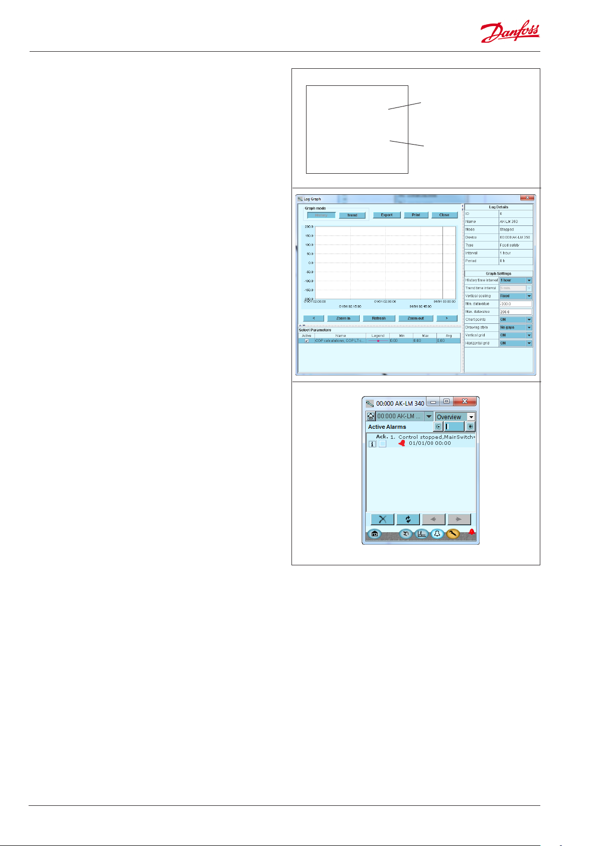
Log
From the log function you can dene the measurements you wish
to be shown.
The collected values can be printed, or you may export them to a
le. You can open the le in Excel or import in AKM.
(The log function is only available via AK-ST 500.)
A log should usually be created on the system unit. The system
unit has a larger memory and can contain more data.
If you are in a service situation you can show measurements in a
trend function. The measurements are then made real-time and
displayed instantly.
■ Power
■ Comm
■ DO1 ■ Status
■ DO2 ■ Service Tool
■ DO3 ■ LON
■ DO4 ■ I/O Extension
■ DO5 ■ Alarm
■ DO6
■ DO7
■ DO8 ■ Service Pin
Slow ash = OK
Quick ash = answer from gateway
Constantly ON = error
Constantly OFF = error
Flash = active alarm/not cancelled
Constant ON = Active alarm/cancelled
Alarm
The display gives you an overview of all active alarms. If you wish
to conrm that you have seen the alarm you can cross it o in the
acknowledge eld.
If you want to know more about a current alarm you can click on it
and obtain an information display on the screen.
A corresponding display exists for all earlier alarms. Here you can
upload information if you need further details about the alarm
history.
6 RS8GV202 © Danfoss 2016-06 AK-LM 340

2. Design of a controller
This section describes how the monitoring unit is designed.
The controller in the system is based on a uniform connection
platform where any deviations from regulation to regulation is
determined by the used top part with a specic software and
by which input and output signals the relevant application will
require. If it is an application with few connections, the controller
module (top part with belonging bottom part) may be sucient.
If it is an application with many connections it will be necessary to
use the controller module plus one or more extension modules.
This section will give you a survey of possible connections plus
assistance in selecting the modules required by your actual
application.
AK-LM 340 RS8GV202 © Danfoss 2016-06 7
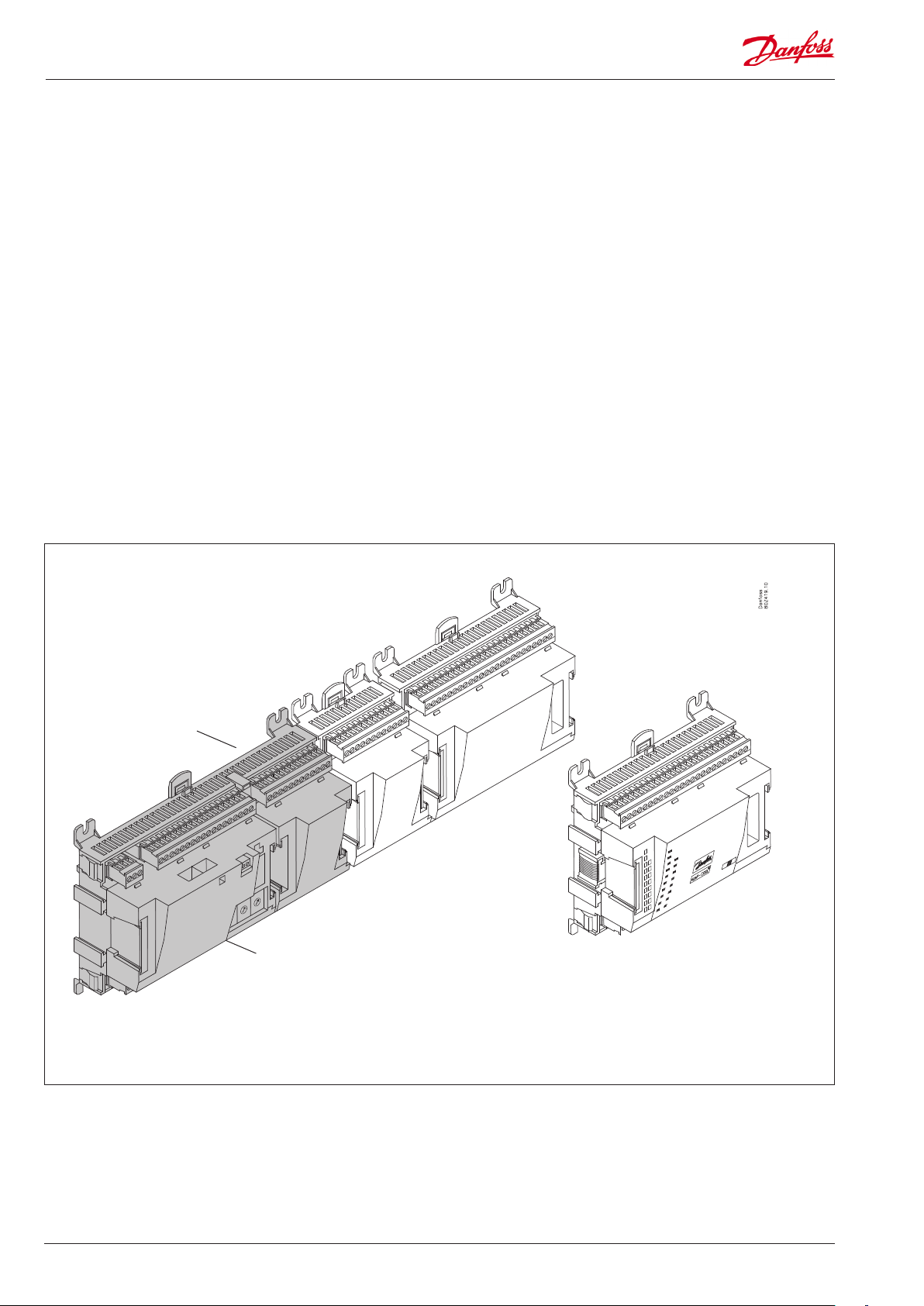
Module survey
• Controller module – capable of handling minor plant requirements.
• Extension modules. When the complexity becomes greater
and additional inputs or outputs are required, modules can be
attached to the controller. A plug on the side of the module will
transmit the supply voltage and data communication between
the modules.
• Top part
The upper part of the controller module contains the
intelligence. This is the unit where the regulation is dened and
where data communication is connected to other controllers in a
bigger network.
• Connection types
There are various types of inputs and outputs. One type may, for
example, receive signals from sensors and switches, another may
receive a voltage signal, and a third type may be outputs with
relays etc. The individual types are shown in the table below.
Extension module with
additional analog inputs
• Optional connection
When a regulation is planned (set up) it will generate a need for
a number of connections distributed on the mentioned types.
This connection must then be made on either the controller
module or an extension module. The only thing to be observed
is that the types must not be mixed (an analog input signal must
for instance not be connected to a digital input).
• Programming of connections
The controller must know where you connect the individual
input and output signals. This takes place in a later conguration
where each individual connection is dened based on the
following principle:
- to which module
- at which point (”terminals”)
- what is connected (e.g. pressure transmitter/type/
pressure range)
Extension module with additional
relay outputs and additional
analog inputs.
Bottem part
Controller with analog inputs and
relay outputs.
Top part
The module with additional relay outputs is
also available in a version where the top part
is provided with change-over switches so
that the relays can be overridden.
8 RS8GV202 © Danfoss 2016-06 AK-LM 340
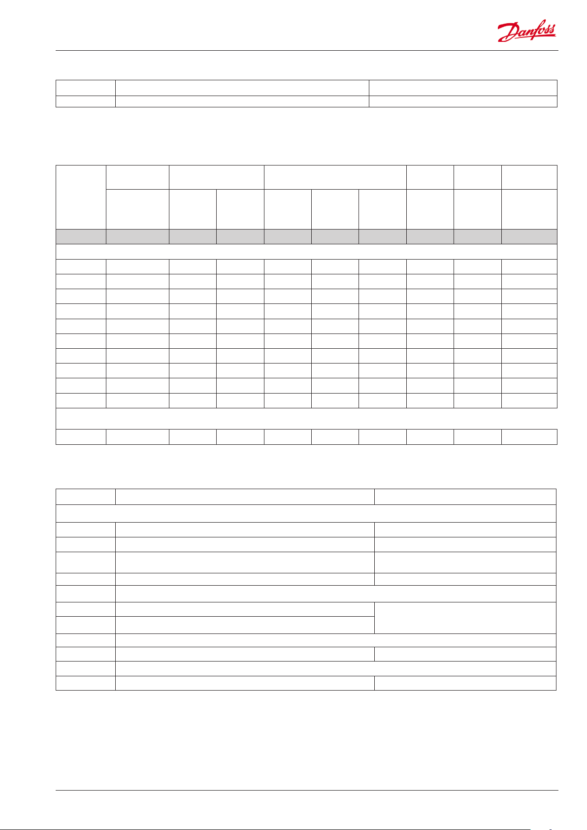
1. Controller
Type Function Application
AK-LM 340 Monitoring unit with PI regulation Monitoring of temperatures, pressure, voltage etc.
2. Extension modules and survey of inputs and outputs
Type Analog
inputs
For sensors, pressure transmitters
etc.
Controller 11 4 4 - - - -
Extension modules
AK-XM 101A 8
AK-XM 102A 8
AK-XM 102B 8
AK-XM 103A 4 4
AK-XM 204A 8
AK-XM 204B 8 x
AK-XM 205A 8 8
AK-XM 205B 8 8 x
AK-XM 107A 4(8)
AK-XM 208C 8 4
The following extension module can be placed on the PC board in the controller module.
There is only room for one module.
AK-OB 110 2
On/O outputs On/o supply voltage
Relay
(SPDT)
Solid state Low voltage
(DI signal)
(max. 80 V)
High voltage
(max. 260 V)
Pulse counter
Low voltage
(max 30 V)
Analog
outputs
0-10 V d.c. For valves
Stepper
output
with step
control
Module with
switches
For override of
relay outputs
3. AK operation and accessories
Type Function Application
Operation
AK-ST 500 Software for operation of AK controllers AK-operation
- Cable between PC and AK controller AK - Com port
-
- Cable between PC and AK controller AK - USB
Accessories Power supply module 230 V / 115 V to 24 V d.c.
AK-PS 075 18 VA, 24 V d.c.
AK-PS 150 36 VA, 24 V d.c.
Accessories Real time clock for use in controllers that require a clock function, but are not wired with data communication.
AK-OB 101A Real time clock with battery backup. To be mounted in an AK controller
Accessories Communication modules for controllers where modules cannot be connected continuously
AK-CM 102 Communication module Data communication for external extension modules
Cable between zero modem cable and AK controller /
Cable between PDA cable and AK controller
AK - RS 232
Supply for controller
On the following pages there is data specic to each module.
AK-LM 340 RS8GV202 © Danfoss 2016-06 9
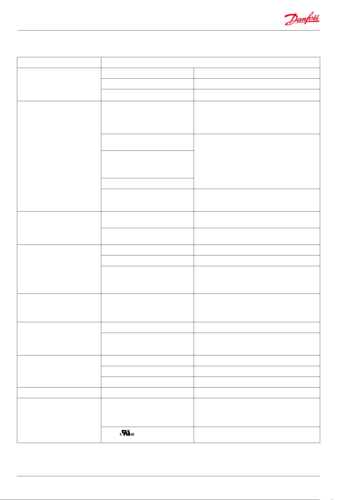
Common data for modules
Supply voltage 24 V d.c./a.c. +/- 20%
Power consumption AK-__ (controller) 8 VA
AK-XM 101, 102, 103, 107 2 VA
AK-XM 204, 205, 208 5 VA
Analog inputs Pt 1000 ohm /0°C Resolution: 0.1°C
Pressure transmitter type AKS 32R / AKS
2050/ AKS 32 (1-5 V)
Other pressure transmitter:
Ratiometric signal
Min. and max. pressure must be set
Min and max. voltage must be set
Voltage signal 0-10 V
Contact function (On/O) On at R < 20 ohm
On/o supply voltage inputs Low voltage
Relay outputs
SPDT
0 / 80 V a.c./d.c.
High voltage
0 / 260 V a.c.
AC-1 (ohmic) 4 A
AC-15 (inductive) 3 A
U Min. 24 V
Accuracy: +/- 0.5°C
+/- 0.5°C between -50°C and +50°C
+/- 1°C between -100°C and -50°C
+/- 1°C between +50°C and +130°C
Resolution:1 mV
Accuracy +/- 10 mV
Max. connection of 5 pressure transmitters on one module
O at R > 2K ohm
(Gold -plated contacts not necessary)
O: U < 2 V
On: U > 10 V
O: U < 24 V
On: U > 80 V
Max. 230 V
Low and high voltage must not be connected to the same
output group
Solid state outputs Can be used for loads that are cut in and
out frequently, e.g. :
rail heat, fans and AKV valve
Ambient temperature During transport -40 to 70°C
During operation -20 to 55°C ,
Enclosure Material PC / ABS
Density IP10 , VBG 4
Mounting For mounting on panel wall or DIN rail
Weight with screw terminals Modules in100- / 200- / controller-series Ca. 200 g / 500 g / 600 g
Approvals EU low voltage directive and EMC require-
ments are complied with
UL 873,
The mentioned data applies to all modules.
If data is specic, this is mentioned together with the module in question.
Capacitive load
The relays cannot be used for the direct connection of capacitive loads such as LEDs
and on/o control of EC motors.
All loads with a switch mode power supply must be connected with a suitable contactor or similar.
Max. 240 V a.c. , Min. 48 V a.c.
Max. 0.5 A,
Leak < 1 mA
Max. 1 AKV
0 to 95% RH (non condensing)
No shock inuences / vibrations
LVD tested according to EN 60730
EMC tested
Immunity according to EN 61000-6-2
Emission according to EN 61000-6-3
UL le number: E166834 for XM modules
UL le number: E31024 for LM modules
10 RS8GV202 © Danfoss 2016-06 AK-LM 340
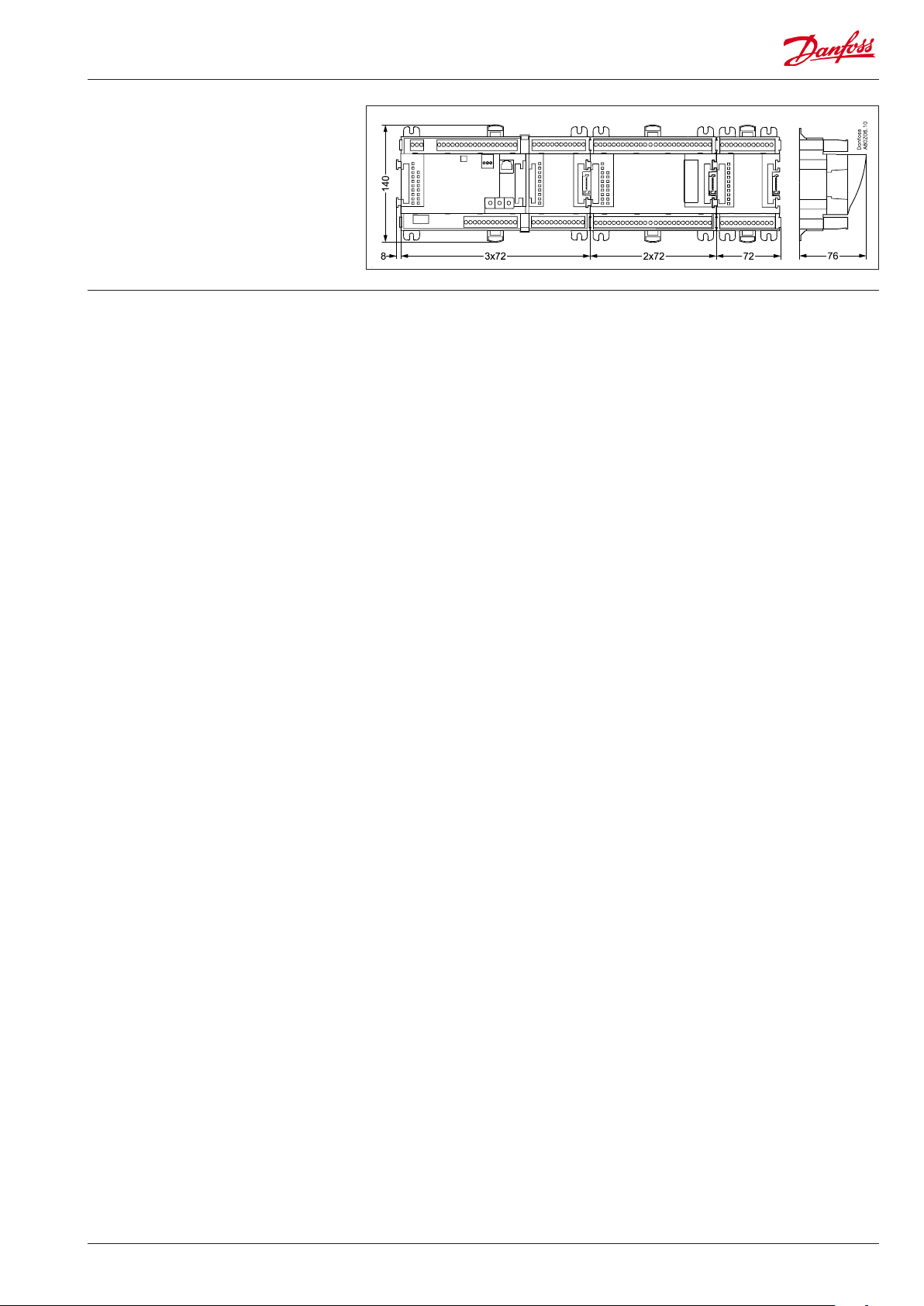
Dimensions
The module dimension is 72 mm.
Modules in the 100-series consist of one
module
Modules in the 200-series consist of two
modules
Controllers consist of three modules
The length of an aggregate unit = n x 72 + 8
AK-LM 340 RS8GV202 © Danfoss 2016-06 11
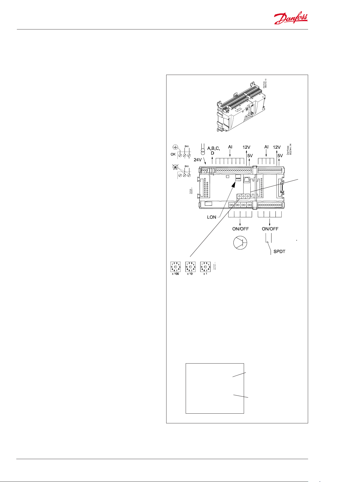
Controller
Function
There are several controllers in the series. The function is
determined by the programmed software, but outwardly the
controllers are identical – they all have the same connection
possibilities:
11 analog inputs for sensors, pressure transmitters, voltage signals
and contact signals.
8 digital outputs, with 4 Solid state outputs and 4 relay outputs
Supply voltage
24 V a.c. or d.c. to be connected to the controller.
The 24 V must not be retransmitted and used by other controllers
as it is not galvanically separated from inputs and outputs. In
other words, you must use a transformer for each controller. Class
II is required. The terminals must not be earthed.
The supply voltage to any extension modules is transmitted via
the plug on the right-hand side.
The size of the transformer is determined by the power
requirement of the total number of modules.
The supply voltage to a pressure transmitter can be taken either
from the 5 V output or from the 12 V output depending on
transmitter type.
PIN
Data communication
If the controller is to be included in a system, communication
must take place via the LON connection.
The installation has to be made as mentioned in the separate
instructions for LON communication.
Address setting
When the controller is connected to a gateway type AKA 245,
the controller’s address must be set between 1 and 119. (If it is a
system manager AK-SM .., then 1-200).
Service PIN
When the controller is connected to the data communication
cable the gateway must have knowledge of the new controller.
This is obtained by pushing the key PIN. The LED “Status” will ash
when the gateway sends an acceptance message.
Operation
The conguration operation of the controller must take place from
the software programme “Service Tool”. The program must be
installed on a PC, and the PC must be connected to the controller
via the network plug on the front of the unit.
Light-emitting diodes
There are two rows with LED’s. They mean:
Left row:
• Voltage supply to the controller
• Communication active with the bottom PC board (red = error)
• Status of outputs DO1 to DO8
Right row:
• Software status (slow ash = OK)
• Communication with Service Tool
• Communication on LON
• Communication with AK-CM 102
• Alarm when LED ashes
- 2 LED’s that are not used
• “Service Pin” switch has been activated
Address
■ Power
■ Comm
■ DO1 ■ Status
■ DO2 ■ Service Tool
■ DO3 ■ LON
■ DO4 ■ I/O Extension
■ DO5 ■ Alarm
■ DO6
■ DO7
■ DO8 ■ Service Pin
Keep the safety
distance!
Low and high
voltage must not
be connected to
the same output
group
Slow ash = OK
Quick ash = answer from gateway
Constantly ON = error
Constantly OFF = error
Flash = active alarm/not cancelled
Constant ON = Active alarm/cancelled
12 RS8GV202 © Danfoss 2016-06 AK-LM 340
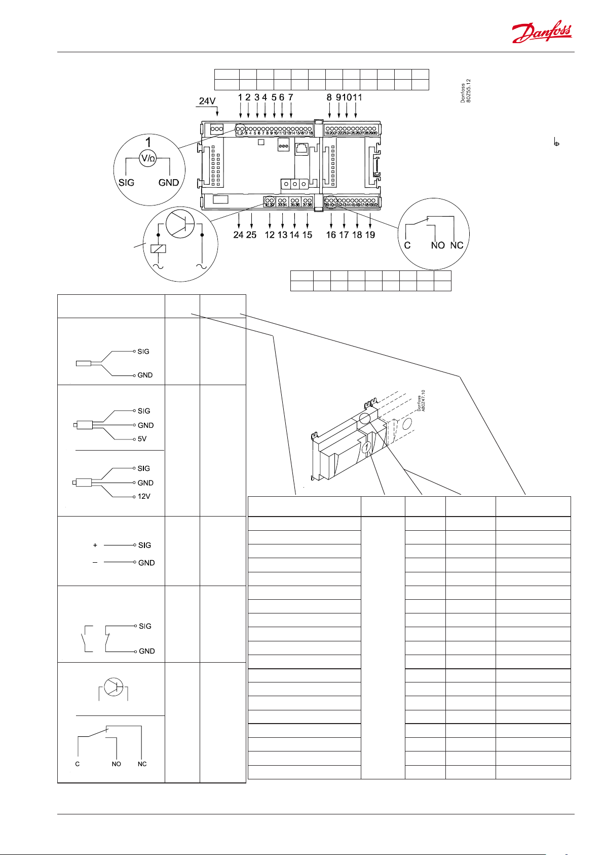
Point
Point 1 2 3 4 5 6 7 8 9 10 11
Type AI1 AI2 AI3 AI4 AI5 AI6 AI7 AI8 AI9 AI10 AI11
Terminal 15: 12 V
Terminal 16: 5 V
Terminal 27: 12 V
Terminal 28: 5 V
Analog
inputs
on 1 - 11
Solid state outputs
on 12 - 15
Relay or AKV coil
fx 230 V a.c.
24 and 25 not
used at monitoring
Signal Signal
type
S
Pt 1000 ohm/0°C
S...
Pt 1000
P
AKS 32R
AKS 32
3: Brown
2: Blue
1: Black
3: Brown
2: Black
1: Red
P...
AKS 32R
AKS 2050
MBS 8250
-1 - xx bar
AKS 32
-1 - zz bar
U
0 - 5 V
Volt
0 - 10 V
input...
On/O Active at:
Closed
/
Open
DO Active at:
AKV
On
/
O
Point 12 13 14 15 16 17 18 19
Type DO1 DO2 DO3 DO4 DO5 DO6 DO7 DO8
Signal Module Point
1 (AI 1) 1 - 2
2 (AI 2) 3 - 4
3 (AI 3) 5 - 6
4 (AI 4) 7 - 8
5 (AI 5) 9 - 10
6 (AI 6) 11 - 12
7 (AI 7) 13 - 14
8 (AI 8) 19 - 20
9 (AI 9) 21 - 22
10 (AI 10) 23 - 24
1
11 (AI 11) 25 - 26
12 (DO 1) 31 - 32
13 (DO 2) 33 - 34
14 (DO 3) 35 - 36
15 (DO 4) 37 - 38
16 (DO 5) 39 - 40- 41
17 (DO6) 42 - 43 - 44
18 (DO7) 45 - 46 - 47
19 (DO8) 48 - 49 - 50
Terminal
17, 18, 29, 30:
(Cable screen)
Relay outputs on
16 - 19
Terminal
Signal type /
Active at
AK-LM 340 RS8GV202 © Danfoss 2016-06 13
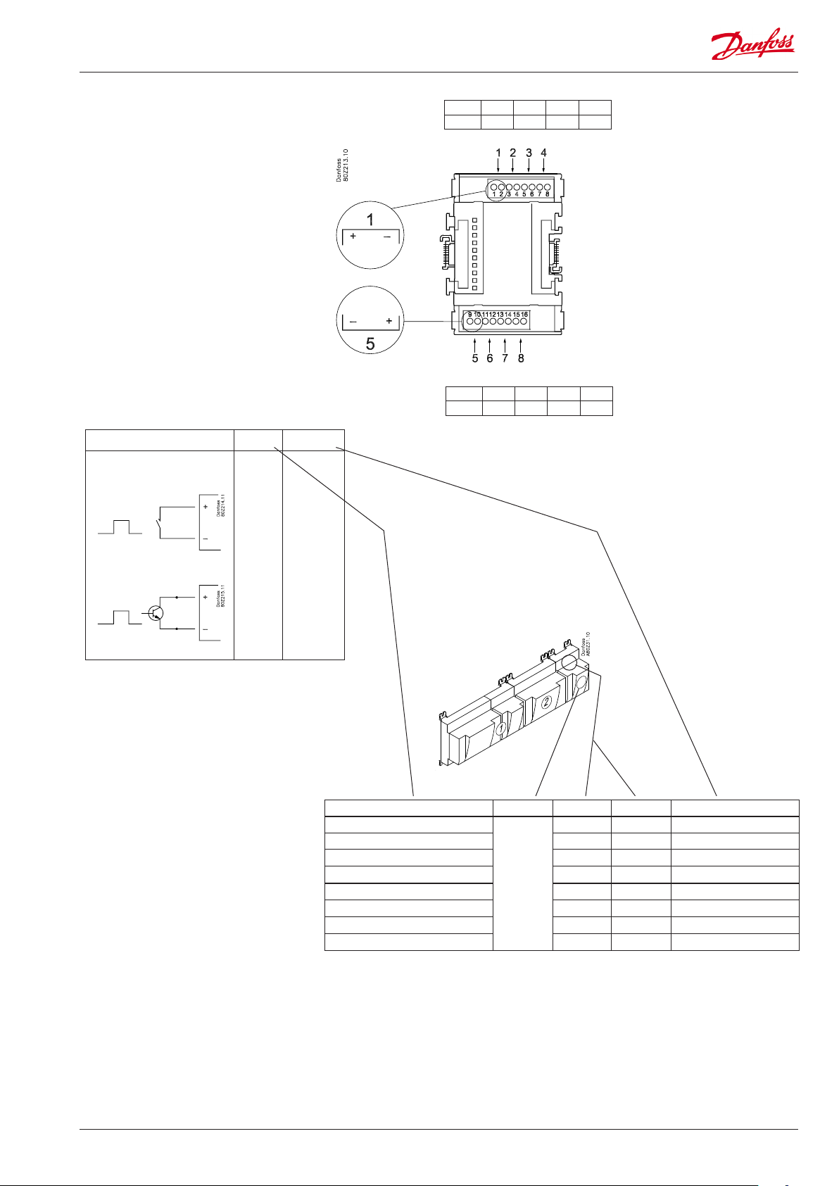
Extension module AK-XM 101A
Function
The module contains 8 analog inputs for sensors, pressure
transmitters, voltage signals and contact signals.
Supply voltage
The supply voltage to the module comes from the previous
module in the row.
Supply voltage to a pressure transmitter can be taken from either
the 5 V output or the 12 V output depending on transmitter type.
Light-emitting diodes
Only the two top LED’s are used. They indicate the following:
• Voltage supply to the module
• Communication with the controller is active (red = error)
14 RS8GV202 © Danfoss 2016-06 AK-LM 340
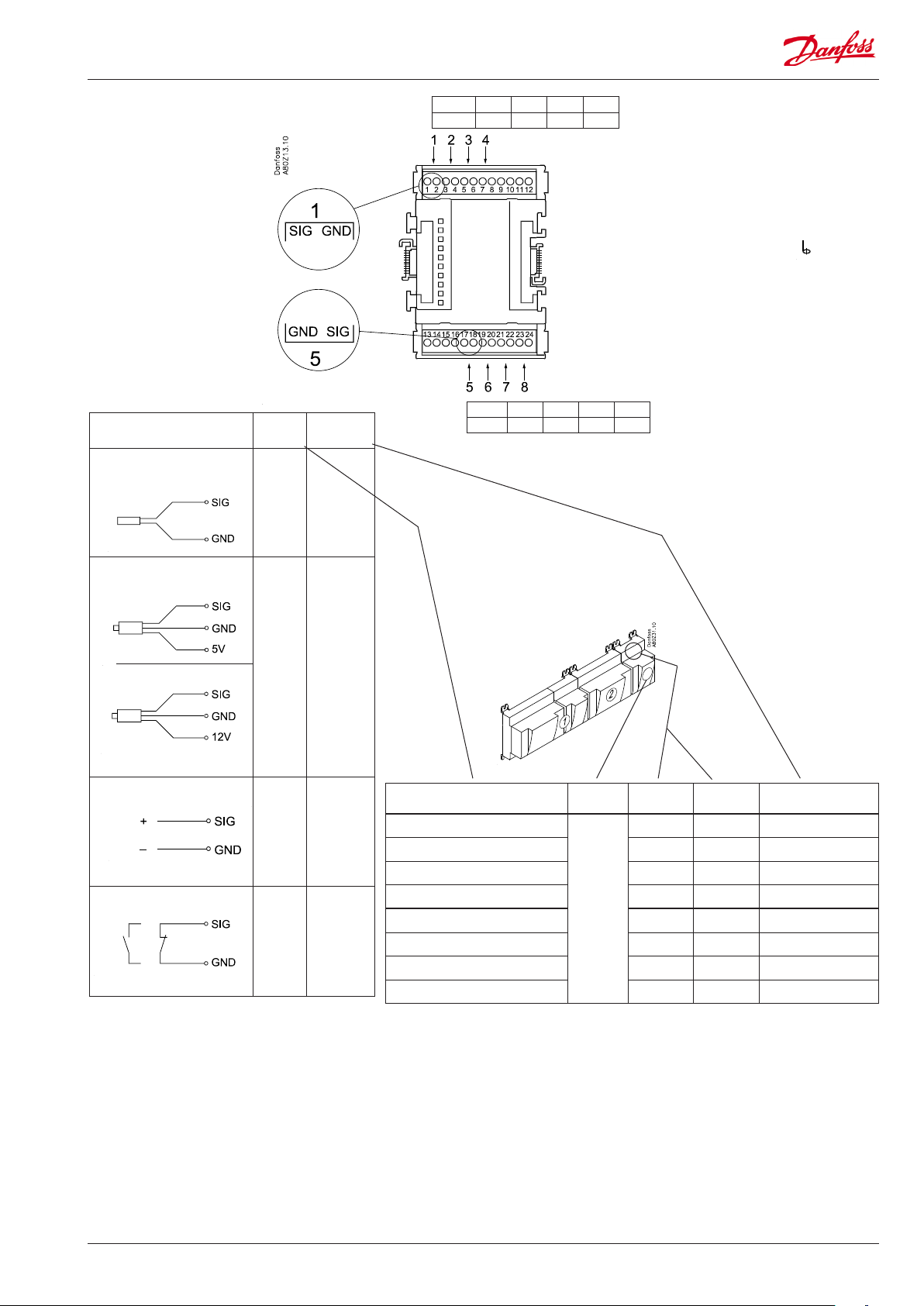
Point
Point 1 2 3 4
Type AI1 AI2 AI3 AI4
Terminal 9: 12 V
Terminal 10: 5 V
S
Pt 1000 ohm/0°C
P
AKS 32R
AKS 2050
AKS 32
At the top the
signal input is
the left of the
two terminals.
At the bottom
the signal input
is the right of the
two terminals.
3: Brown
2: Blue
1: Black
3: Brown
2: Black
1: Red
Signal Signal
type
S...
Pt 1000
AKS 32R
AKs 2050
MBS 8250
P...
-1 - xx bar
AKS 32
-1 - zz bar
Terminal 15: 5 V
Terminal 16: 12 V
Terminal
11, 12, 13, 14:
(Cable screen)
Point 5 6 7 8
Type AI5 AI6 AI7 AI8
U
On/O
V...
Day/
Night
Door
Defrost
0 - 5 V
0 - 10 V
Active at:
Closed
/
Open
Signal Module Point
1 (AI 1) 1 - 2
2 (AI 2) 3 - 4
3 (AI 3) 5 - 6
4 (AI 4) 7 - 8
5 (AI 5) 17 - 18
6 (AI 6) 19 - 20
7 (AI 7) 21 - 22
8 (AI 8) 23 - 24
Terminal
Signal type /
Active at
AK-LM 340 RS8GV202 © Danfoss 2016-06 15
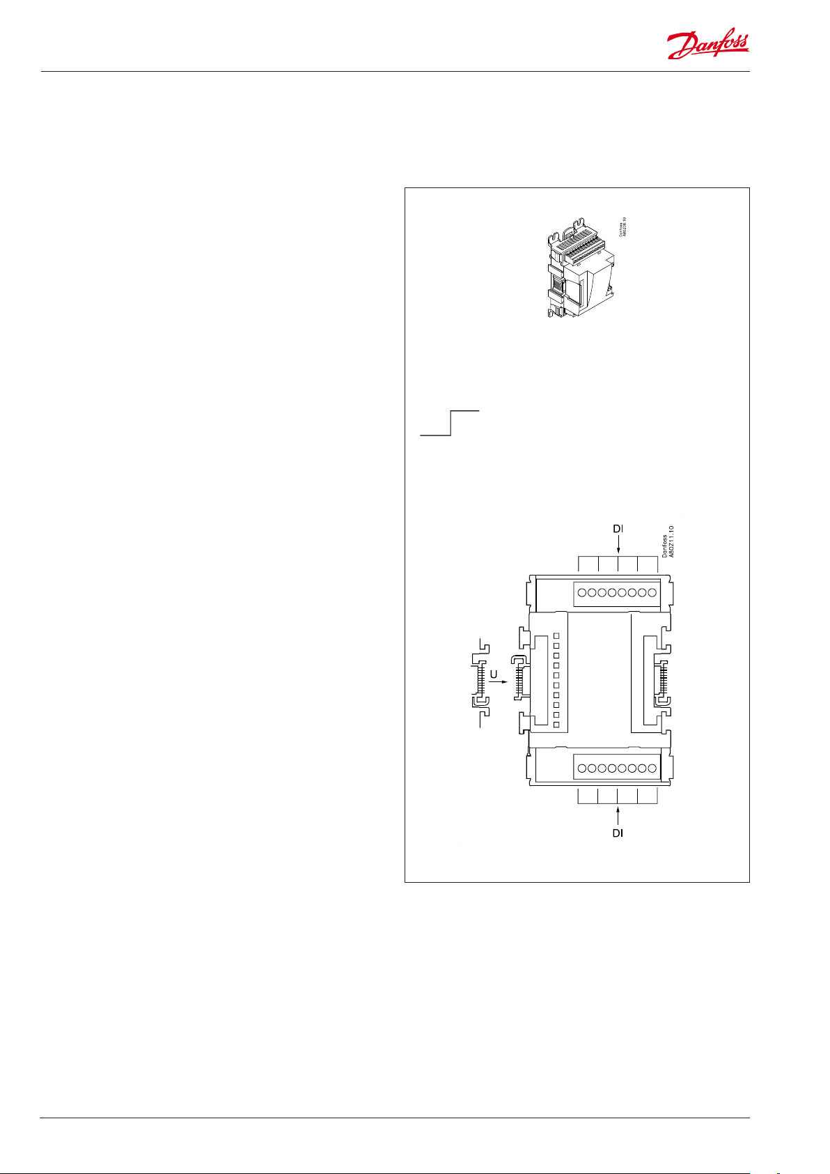
Extension module AK-XM 102A / AK-XM 102B
Function
The module contains 8 inputs for on/o voltage signals.
Signal
AK-XM 102A is for low voltage signals.
AK-XM 102B is for high voltage signals.
Supply voltage
The supply voltage to the module comes from the previous
module in the row.
Light-emitting diodes
They indicate:
• Voltage supply to the module
• Communication with the controller is active (red = error)
• Status of the individual inputs 1 to 8 (when lit = voltage)
AK-XM 102A
Max. 24 V
On/O:
On: DI > 10 V a.c.
O: DI < 2 V a.c.
AK-XM 102B
Max. 230 V
On/O:
On: DI > 80 V a.c.
O: DI < 24 V a.c.
16 RS8GV202 © Danfoss 2016-06 AK-LM 340
Point
DI
Point 1 2 3 4
Type DI1 DI2 DI3 DI4
Point 5 6 7 8
Type DI5 DI6 DI7 DI8
Signal Active at
AK-XM 102A: Max. 24 V
AK-XM 102B: Max. 230 V
Day/
Night
Door.
Defrost
Closed
(voltage on)
/
Open
(voltage o)
(The module can not register a pulse signal from e.g. a
reset function.)
Signal Module Point Terminal Active at
1 (DI 1) 1 - 2
2 (DI 2) 3 - 4
3 (DI 3) 5 - 6
4 (DI 4) 7 - 8
5 (DI 5) 9 - 10
6 (DI 6) 11 - 12
7 (DI 7) 13 - 14
8 (DI 8) 15 - 16
AK-LM 340 RS8GV202 © Danfoss 2016-06 17

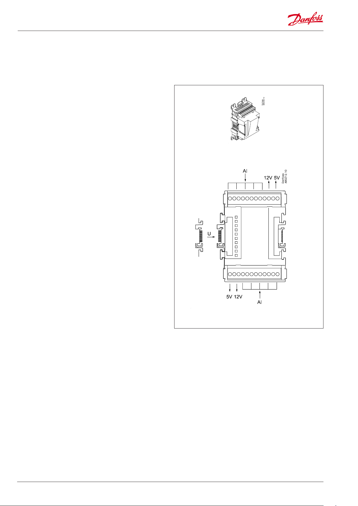
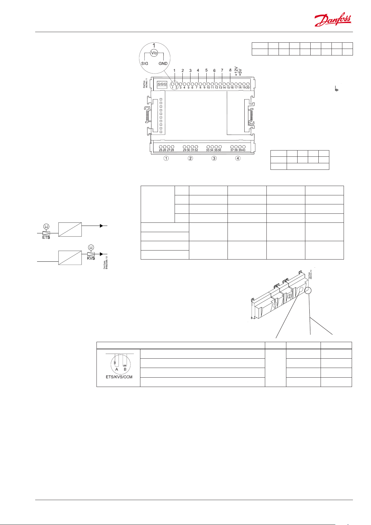
Extension module AK-XM 103A
Function
The module contains :
4 analog inputs for sensors, pressure transmitters, voltage signals
and contact signals.
4 analog voltage outputs of 0 - 10 V
Supply voltage
The supply voltage to the module comes from the previous
module in the row.
Supply voltage to a pressure transmitter can be taken from either
the 5 V output or the 12 V output depending on transmitter type.
Galvanic isolation
The inputs are galvanically separated from the outlets.
The outlets AO1 and AO2 are galvanically separated from AO3 and
AO4.
Light-emitting diodes
Only the two top LED’s are used. They indicate the following:
• Voltage supply to the module
• Communication with the controller is active (red = error)
Max. load
I < 2.5 mA
R > 4 kΩ
18 RS8GV202 © Danfoss 2016-06 AK-LM 340
Punkt
At the top the
signal input is
the left of the
two terminals.
At the bottom
the signal input
is the right of the
two terminals.
Point 1 2 3 4
Type AI1 AI2 AI3 AI4
Terminal 9: 12 V
Terminal 10: 5 V
Terminal
11, 12:
(Cable screen)
Galvanic isolation:
AI 1-4 ≠ AO 1-2 ≠ AO 3-4
S
Pt 1000 ohm/0°C
P
AKS 32R
AKS 32
U
On/O
3: Brun
2: Blå
1: Sort
3: Brun
2: Sort
1: Rød
Signal Signal
type
Pt 1000
S...
AKS 32R /
AKS 2050
MBS 8250
P...
-1 - xx bar
AKS 32
-1 - zz bar
V...
0 - 5 V
0 - 10 V
Active at:
Day/
Night
Door
Closed
Open
Level
switch
Point 5 6 7 8
Type AO1 AO2 AO3 AO 4
Signal Module Point Terminal Signal type /Active at
1 (AI 1) 1 - 2
2 (AI 2) 3 - 4
3 (AI 3) 5 - 6
4 (AI 4) 7 - 8
5 (AO 1) 17 - 18
/
6 (AO 2) 19 - 20
7 (AO 3) 21 - 22
8 (AO 4) 23 - 24
AO
0-10 V
AK-LM 340 RS8GV202 © Danfoss 2016-06 19
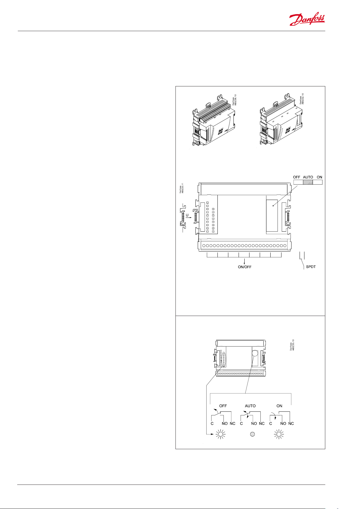
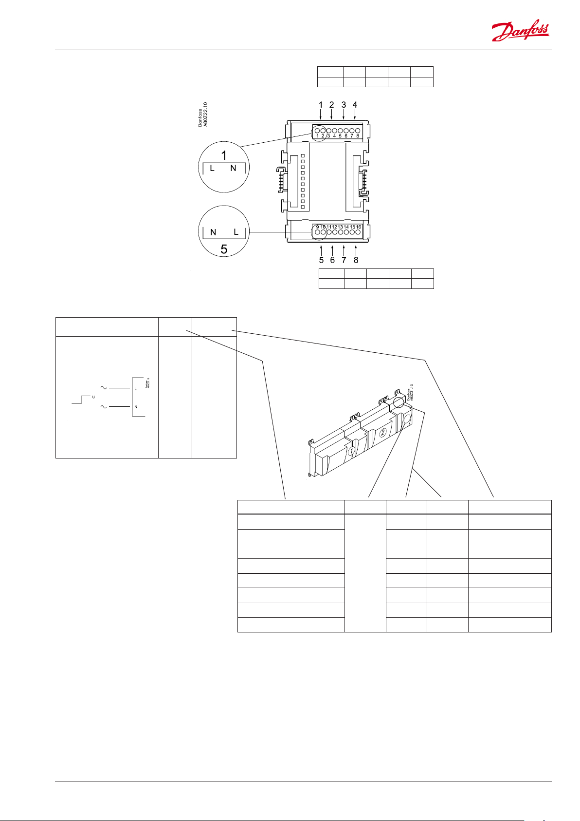
Extension module AK-XM 204A / AK-XM 204B
Function
The module contains 8 relay outputs.
Supply voltage
The supply voltage to the module comes from the previous
module in the row.
AK-XM 204B only
Override of relay
Eight change-over switches at the front make it possible to
override the relay’s function.
Either to position OFF or ON.
In position Auto the controller carries out the control.
Light-emitting diodes
There are two rows with LED’s. They indicate the following:
Left row:
• Voltage supply to the controller
• Communication active with the bottom PC board (red = error)
• Status of outputs DO1 to DO8
Right row: (AK-XM 204B only):
• Override of relays
ON = override
OFF = no override
AK-XM 204A AK-XM 204B
Fuses
Behind the upper part there is a fuse for each output.
Max. 230 V
AC-1: max. 4 A (ohmic)
AC-15: max. 3 A (Inductive)
AK-XM 204B
Override of relay
Keep the safety distance!
Low and high voltage
must not be connected to
the same output group
20 RS8GV202 © Danfoss 2016-06 AK-LM 340
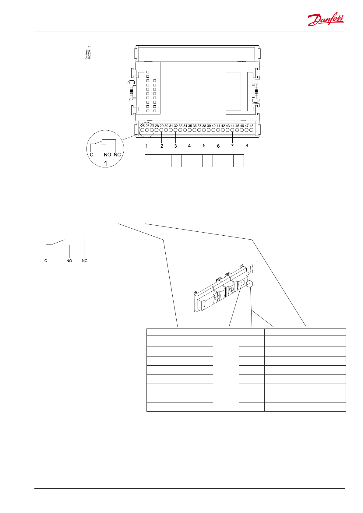
Point
DO
Signal Active at
Fan
Alarm
Light
Rail-heat
Defrost
Night
blinds
Valves
Compressor
On
/
O
Point 1 2 3 4 5 6 7 8
Type DO1 DO2 DO3 DO4 DO5 DO6 DO7 DO8
Signal Module Point Terminal Active at
1 (DO 1) 25 - 26 - 27
2 (DO 2) 28 - 29 - 30
3 (DO 3) 31 - 32 - 33
4 (DO 4) 34 - 35 -36
5 (DO 5) 37 - 38 - 39
6 (DO 6) 40 - 41 - 42
7 (DO 7) 43 - 44 - 45
8 (DO 8) 46 - 47 - 48
AK-LM 340 RS8GV202 © Danfoss 2016-06 21
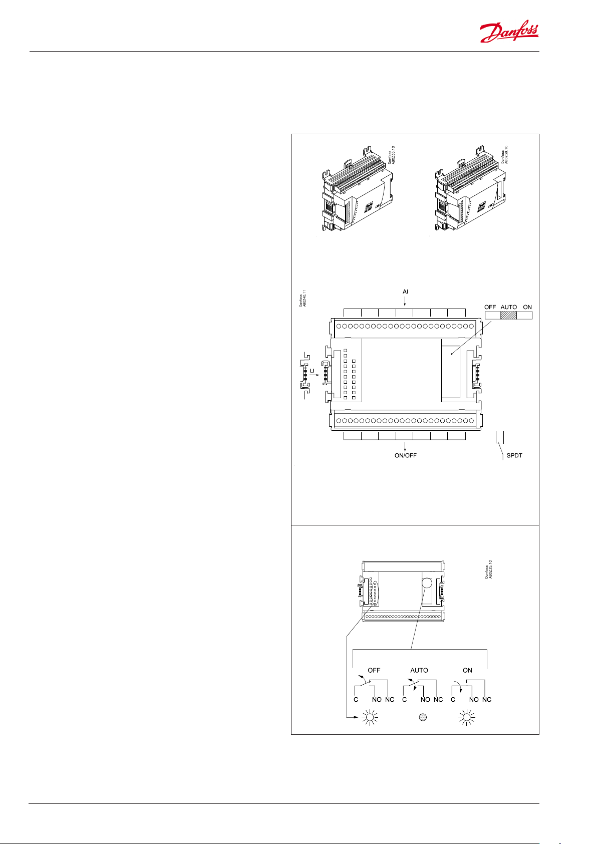
Extension module AK-XM 205A / AK-XM 205B
Function
The module contains:
8 analog inputs for sensors, pressure transmitters, voltage signals
and contact signals.
8 relay outputs.
Supply voltage
The supply voltage to the module comes from the previous
module in the row.
AK-XM 205B only
Override of relay
Eight change-over switches at the front make it possible to
override the relay’s function.
Either to position OFF or ON.
In position Auto the controller carries out the control.
Light-emitting diodes
There are two rows with LED’s. They mean:
Left row:
• Voltage supply to the controller
• Communication active with the bottom PC board (red = error)
• Status of outputs DO1 to DO8
Right row: (AK-XM 205B only):
• Override of relays
ON = override
OFF = no override
AK-XM 205A AK-XM 205B
max. 10 V
Fuses
Behind the upper part there is a fuse for each output.
Max. 230 V
AC-1: max. 4 A (ohmic)
AC-15: max. 3 A (Inductive)
AK-XM 205B
Override of relay
Keep the safety distance!
Low and high voltage
must not be connected to
the same output group
22 RS8GV202 © Danfoss 2016-06 AK-LM 340
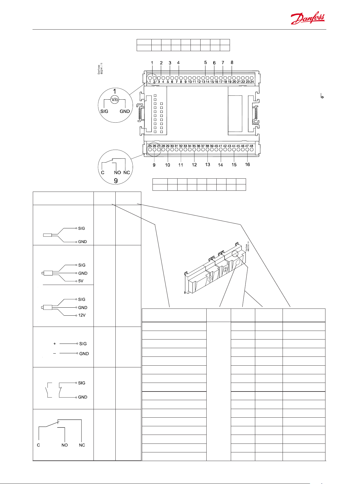
Point
S
Pt 1000 ohm/0°C
Signal Signal
type
Pt 1000
S...
Point 1 2 3 4 5 6 7 8
Type AI1 AI2 AI3 AI4 AI5 AI6 AI7 AI8
Terminal 9: 12 V
Terminal 10: 5 V
Terminal 21: 12 V
Terminal 22: 5 V
Terminal 11, 12, 23, 24 :
(Cable screen)
Point 9 10 11 12 13 14 15 16
Type DO1 DO2 DO3 DO4 DO5 DO6 DO7 DO8
P
AKS 32R
AKS 2050
AKS 32
U
On/O
DO
3: Brown
2: Blue
1: Black
3: Brown
2: Black
1: Red
P...
V...
Day/
Night
Door
Defrost
Fan
Alarm
Light
Rail heat
Defrost
Night
blinds
Valves
Compressors
AKS 32R
AKS 2050
MBS 8250
-1 - xx bar
AKS 32
-1 - zz bar
0 - 5 V
0 - 10 V
Active at:
Closed
/
Open
Active at:
on
/
O
Signal Module Point
1 (AI 1) 1 - 2
2 (AI 2) 3 - 4
3 (AI 3) 5 - 6
4 (AI 4) 7 - 8
5 (AI 5) 13 - 14
6 (AI 6) 15 - 16
7 (AI 7) 17 - 18
8 (AI 8) 19 -20
9 (DO 1) 25 - 26 - 27
10 (DO 2) 28 - 29 - 30
11 (DO 3) 31 - 30 - 33
12 (DO 4) 34 - 35 - 36
13 (DO 5) 37 - 36 - 39
14 (DO6) 40 - 41 - 42
15 (DO7) 43 - 44 - 45
16 (DO8) 46 - 47 - 48
Terminal
Signal type /
Active at
AK-LM 340 RS8GV202 © Danfoss 2016-06 23

Extension module AK-XM 107A
Function
The module contains eight inputs for pulse counting.
AK-LM 340 can detect signals from 8 pulse signals.
Supply voltage
The supply voltage for the module comes from the previous module in the sequence.
LEDs
These indicate the following:
• Voltage of the module
• Communication with the controller is active (red = error)
(There is no LED indication for the individual signal inputs)
Signal
The signal is registered in accordance with DIN 43864.
Rise times and fall times must be less than 5 ms.
On and o times must be greater than 30 ms.
24 RS8GV202 © Danfoss 2016-06 AK-LM 340
Point
CI
Point 1 2 3 4
Type CI1 CI2 CI3 CI4
Point 5 6 7 8
Type CI5 CI6 CI7 CI8
Signal Active at
Pulse - - -
Signal Module Point Terminal Active at
1 (CI 1) 1 - 2 - - -
2 (CI 2) 3 - 4 - - -
3 (CI 3) 5 - 6 - - -
4 (CI 4) 7 - 8 - - -
5 (CI 5) 9 - 10 - - -
6 (CI 6) 11 - 12 - - -
7 (CI 7) 13 - 14 - - -
8 (CI 8) 15 - 16 - - -
AK-LM 340 RS8GV202 © Danfoss 2016-06 25
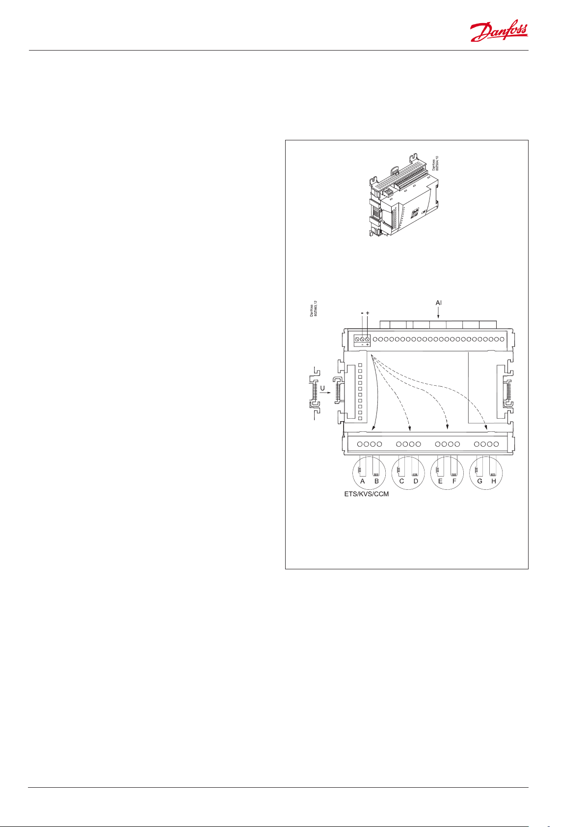
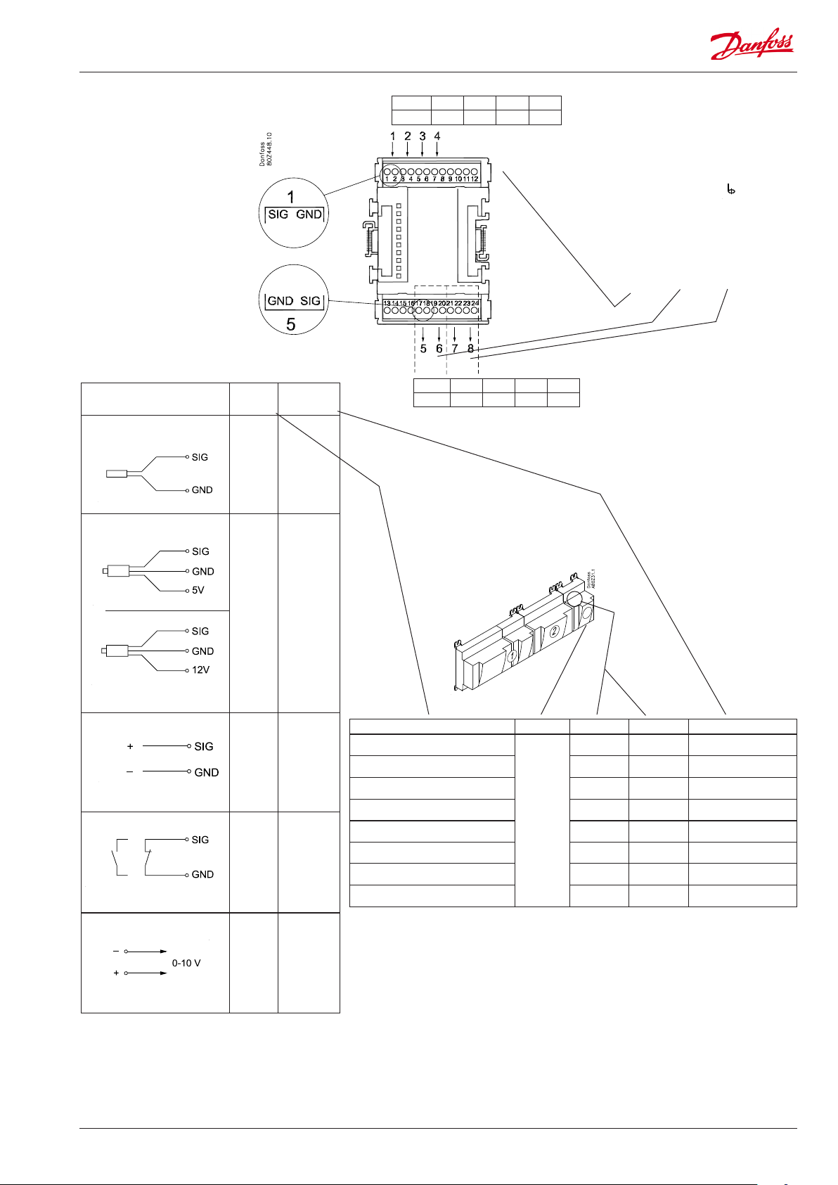
Extension module AK-XM 208C
Function
The module contains:
8 analog inputs for sensors, pressure transmitters, voltage signals
and contact signals.
4 outputs for stepper motors.
Supply voltage
The supply voltage to the module comes from the previous
module in the row.
The supply voltage to the valves must be from a separate supply,
which must be galvanically separated from the supply for the
control range. 24 V d.c. +/-20%.
(Power requirements: 7.8 VA for controller + 1.3 VA per valve).
A UPS may be necessary if the valves need to open/close during a
power failure.
Light-emitting diodes
There is one row with LED’s. It indicate the following:
• Voltage supply to the module
• Communication active with the bottom PC board (red = error)
• Status of outputs AO1 to AO4
Separate voltage
supply is required
max. 10 V
24 V d.c. 13 VA
Output:
24 V d.c.
I
= 500 m A / coil
max.
20-500 step/s
26 RS8GV202 © Danfoss 2016-06 AK-LM 340
Point
CCM
Step /
Terminal
ETS
CCM / CCMT
KVS 15
KVS 42-54
Point 1 2 3 4 5 6 7 8
Type AI1 AI2 AI3 AI4 AI5 AI6 AI7 AI8
Terminal 17: 12 V
Terminal 18: 5 V
Terminal 19, 20:
(Cable screen)
Point 9 10 11 12
Step 1 2 3 4
Type AO
1 25 26 27 28
2 29 30 31 32
3 33 34 35 36
4 37 38 39 40
White Black Red Green
White Black Green Red
Valve Module Step Terminal
1 (point 9) 25 - 28
2 (point 10) 29 - 32
3 (point 11) 33 - 36
4 (point 12) 37 - 40
AK-LM 340 RS8GV202 © Danfoss 2016-06 27
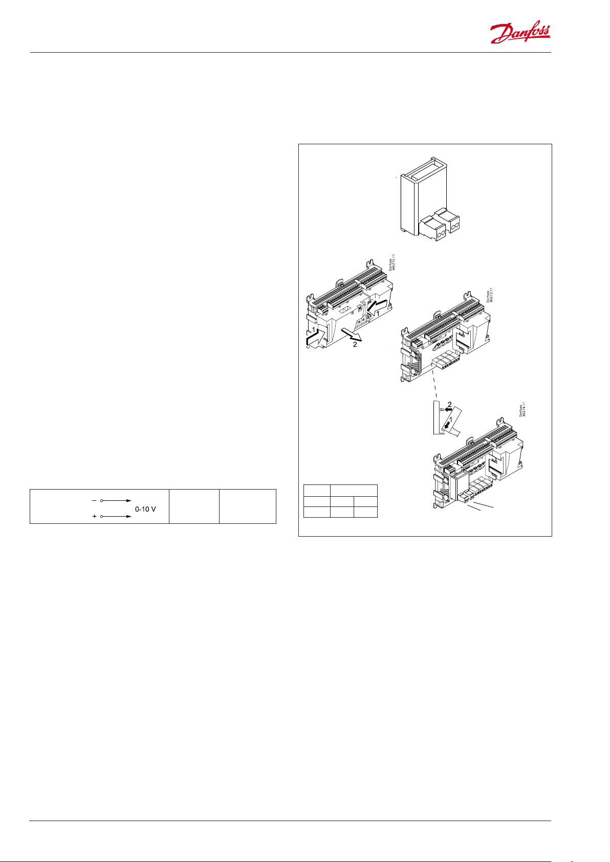
Extension module AK-OB 110
Function
The module contains two analog voltage outputs of 0 – 10 V.
Supply voltage
The supply voltage to the module comes from the controller
module.
Placing
The module is placed on the PC board in the controller module.
Point
The two outputs have points 24 and 25. They are shown on the
earlier page where the controller is also mentioned.
Max. load
I < 2.5 mA
R > 4 kohm
AO
AO 0 - 10 V
Module
Point 24 25
Type AO1 AO2
1
AO2
AO1
28 RS8GV202 © Danfoss 2016-06 AK-LM 340
 Loading...