

Danfoss ADAP-KOOL AK-HP 780 Design Manual
Design Guide
Heat pump controller
with oil management
AK-HP 780
ADAP-KOOL® Refrigeration control systems

Contents
1. Introduction ............................................................................. 3
Application .................................................................................................. 3
Principles...................................................................................................... 4
2. Design of a controller ..............................................................7
Module survey ........................................................................................... 8
Common data for modules .................................................................10
Controller ...........................................................................................12
Extension module AK-XM 101A .................................................14
Extension module AK-XM 102A / AK-XM 102B .....................16
Extension module AK-XM 204A / AK-XM 204B .....................18
Extension module AK-XM 205A / AK-XM 205B .....................20
Extension module AK-OB 110 ....................................................22
Extension module AK-OB 101A..................................................23
Extension module EKA 163B / EKA 164B ................................ 24
Power supply module AK-PS 075 / 150 ...................................25
Preface to design ....................................................................................26
Functions ............................................................................................26
Connections ...................................................................................... 27
Limitations ......................................................................................... 27
Design of a compressor and pump control ..................................28
Procedure: ..........................................................................................28
Sketch .................................................................................................. 28
Functions ............................................................................................28
Connections ...................................................................................... 29
Planning table .................................................................................. 31
Length .................................................................................................32
Linking of modules ......................................................................... 32
Determine the connection points ............................................33
Connection diagram ...................................................................... 34
Supply voltage ................................................................................. 35
Ordering ..................................................................................................... 36
3. Mounting and wiring .............................................................37
Mounting ................................................................................................... 38
Mounting of analog output module ........................................ 38
Mounting of extension module on the basic module ....... 39
Wiring .......................................................................................................... 40
4. Conguration and operation ................................................43
Conguration ...........................................................................................45
Connect PC or PDA ......................................................................... 45
Authorization .................................................................................... 46
Unlock the conguration of the controllers ..........................47
System setup ....................................................................................48
Set plant type ................................................................................... 49
Set control of compressors ..........................................................50
Set oil management ....................................................................... 53
Setup control of the pump ..........................................................55
Setup Display .................................................................................... 56
Setup general alarm inputs ......................................................... 57
Setup separate thermostat functions ...................................... 58
Setup separate voltage functions ............................................. 59
Conguration of inputs and outputs .......................................60
Set alarm priorities..........................................................................62
Lock conguration ..........................................................................64
Check conguration .......................................................................65
Check of connections ............................................................................ 67
Check of settings.....................................................................................69
Schedule function .................................................................................. 71
Installation in network .......................................................................... 72
First start of control ................................................................................73
Start control ......................................................................................74
Manual capacity control ............................................................... 75
5. Regulating functions .............................................................77
Suction group ..........................................................................................78
Controlling sensor .........................................................................78
Reference ...........................................................................................79
Capacity control of compressors ...............................................80
Compressor timers ..................................................................81
Capacity distribution methods ........................................... 82
Power pack types – compressor combinations ............83
Load shedding ..........................................................................87
Safety functions ............................................................................... 88
Oil management..............................................................................90
Pump ...........................................................................................................92
General monitoring functions ...........................................................93
Miscellaneous ..........................................................................................94
Appendix A – Compressor combinations and coupling pat-
terns ............................................................................................................. 97
Appendix B - Alarm texts ...................................................................102
2 Heat pump controller RS8GF202 © Danfoss 2015-08 AK-HP 780
1. Introduction
Application
AK-HP 780 is a complete heat pump regulating for capacity
control of compressors and temperature regulating of a receiver.
The controller is with oil management, making it suitable for CO2
plants.
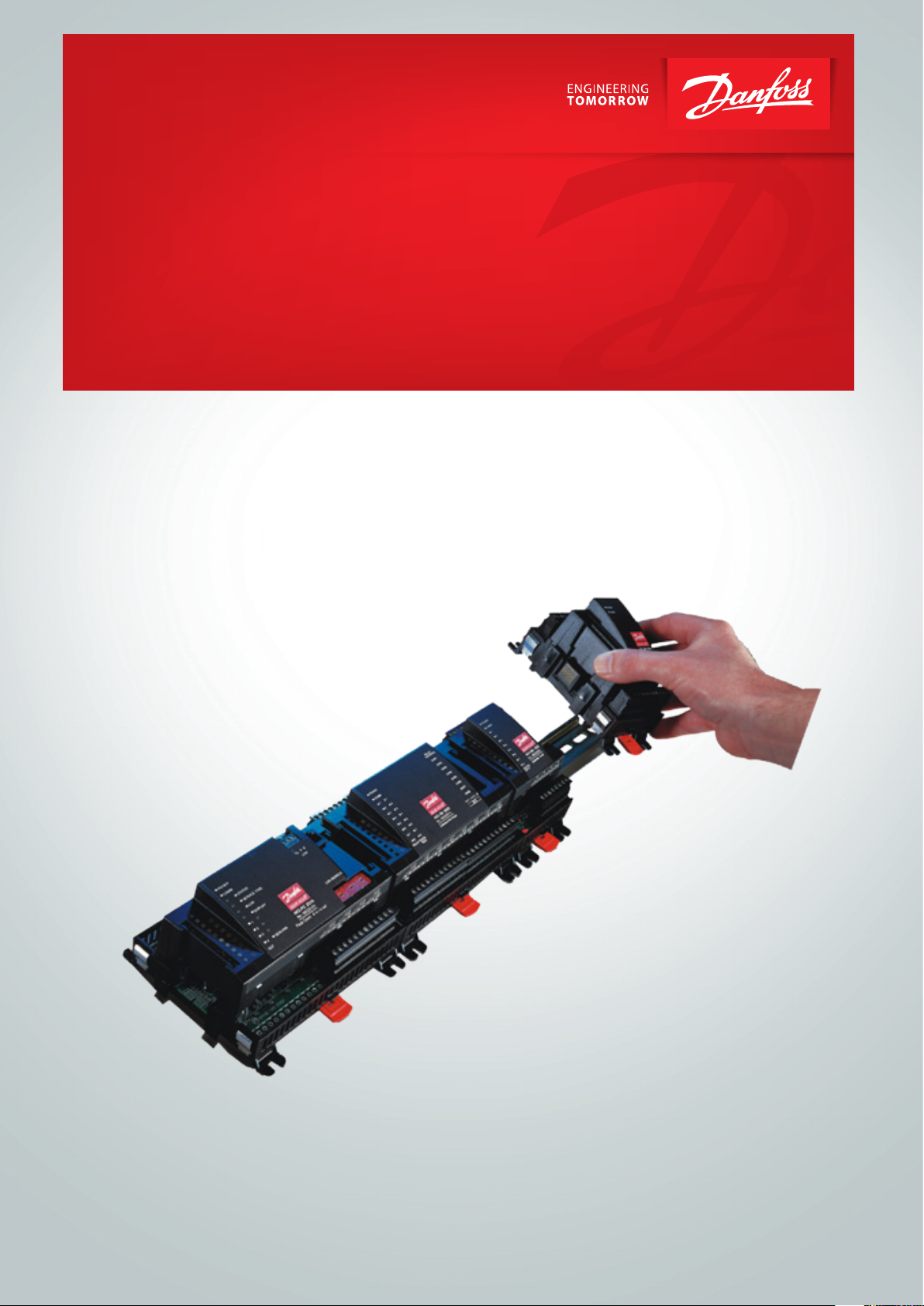
The controller’s main function is to control compressors and
pump, so that operation all the time takes place at the energyoptimum pressure conditions. Both suction pressure and discharge pressure are monitored with the belonging safety function
and alarm function. Capacity control can be carried out by media
temperature Sctrl and S7.
Among the dierent functions are:
- Capacity control of up to 8 compressors
- Up to 3 unloaders for each compressor
- Oil management. Either shared or individual for all of the compressor's oil valves. Receiver pressure control.
- Speed control of one or two compressors
- Up to 6 safety inputs for each compressor
- Option for capacity limitation to minimize consumption peaks
- Safety monitoring of high pressure / low pressure / discharge
temperature
- Capacity control of a pump. Either On/O or speed control
- Safety monitoring of pump ow
- The status of the outputs and inputs is shown by means of lightemitting diodes on the front panel
- Alarm signals can be generated directly from the controller and
via data communication
- Alarms are shown with texts so that the cause of the alarm is
easy to see.
- Plus some completely separate functions that are totally independent of the regulation – such as alarm, thermostat and
pressure control functions, safety functions at cold start up, P0
limitation.
Example
Compressor control
Pump control
Oil management
SW = 1.4x
AK-HP 780 Heat pump controller RS8GF202 © Danfoss 2015-08 3
Principles
The great advantage of this series of controllers is that it can be
extended as the size of the plant is increased. It has been developed for heat pump control, but not for any specic application –
variation is created through the read-in software and the way you
choose to dene the connections.
It is the same modules that are used for each regulation and the
composition can be changed, as required. With these modules
(building blocks) it is possible to create a multitude of various
kinds of regulations. But it is you who must help adjusting the
regulation to the actual needs – these instructions will assist you
to nd your way through all the questions so that the regulation
can be dened and the connections made.
Controller
Top part
Advantages
• The controller’s size can “grow” as systems grow
• The software can be set for one or more regulations
• Several regulations with the same components
• Extension-friendly when systems requirements are changed
• Flexible concept:
- Controller series with common construction
- One principle – many regulation uses
- modules are selected for the actual connection requirements
- The same modules are used from regulation to regulation
Extension modules
Bottom part
The controller is the cornerstone of the regulation. The module has inputs and
outputs capable of handling small systems.
• The bottom part – and hence the terminals – are the same for all controller types.
• The top part contains the intelligence with software. This unit will vary according
to controller type. But it will always be supplied together with the bottom part.
• In addition to the software the top part is provided with connections for data
communication and address setting.
Examples
A regulation with few connections can
be performed with the controller module
alone
If the system grows and more functions have to be controlled, the regulation can be
extended.
With extra modules more signals can be received and more relays cut in and out –
how many of them – and which – is determined by the relevant application.
If there are many connections one or more
extension modules have to be mounted
4 Heat pump controller RS8GF202 © Danfoss 2015-08 AK-HP 780
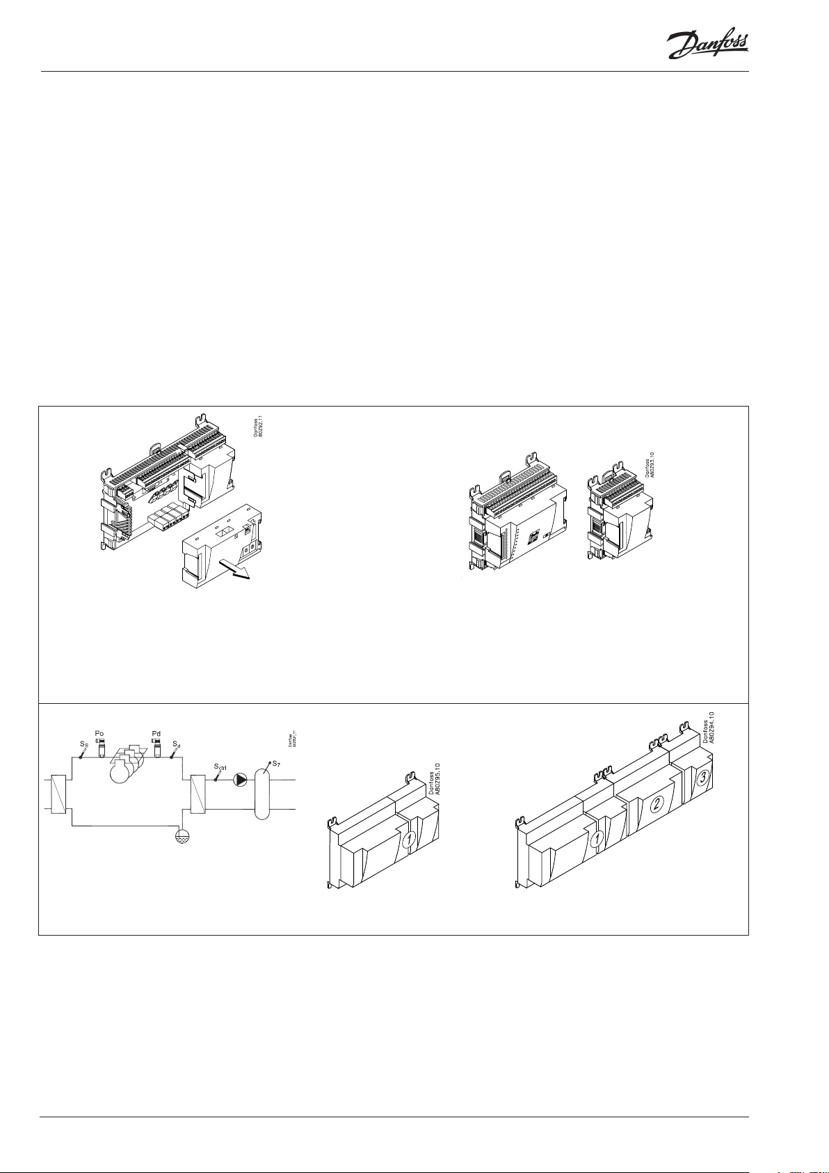
Direct connection
Setup and operation of an AK controller must be accomplished via
the “AK-Service Tool” software program.
The programme is installed on a PC, and setup and operation of
the various functions are carried out via the controller’s menu
displays.
Displays
The menu displays are dynamic, so that dierent settings in one
menu will result in dierent setting possibilities in other menus.
A simple application with few connections will give a setup with
few settings.
A corresponding application with many connections will give a
setup with many settings.
From the overview display there is access to further displays for
the compressor regulation and the pump regulation.
At the bottom of the display there is access to a number of general
functions, such as “time table”, “manual operation”, “log function”,
“alarms”, and “service” (conguration).
Network linking
The controller can be linked up into a network together with other
controllers in an ADAP-KOOL® refrigeration control system. After
the setup operation can be performed at a distance with, say, our
software program type AKM.
Users
The controller comes supplied with several languages, one of
which can be selected and employed by the user. If there are
several users, they may each have their choice of language. All
users must be assigned a user prole which either gives access to
full operation or gradually limits the operation to the lowest level
that only allows you “to see”.
Language selection is part of the service tool settings.
If the language selection is not available in the service tool for the
current regulator, English texts will be displayed.
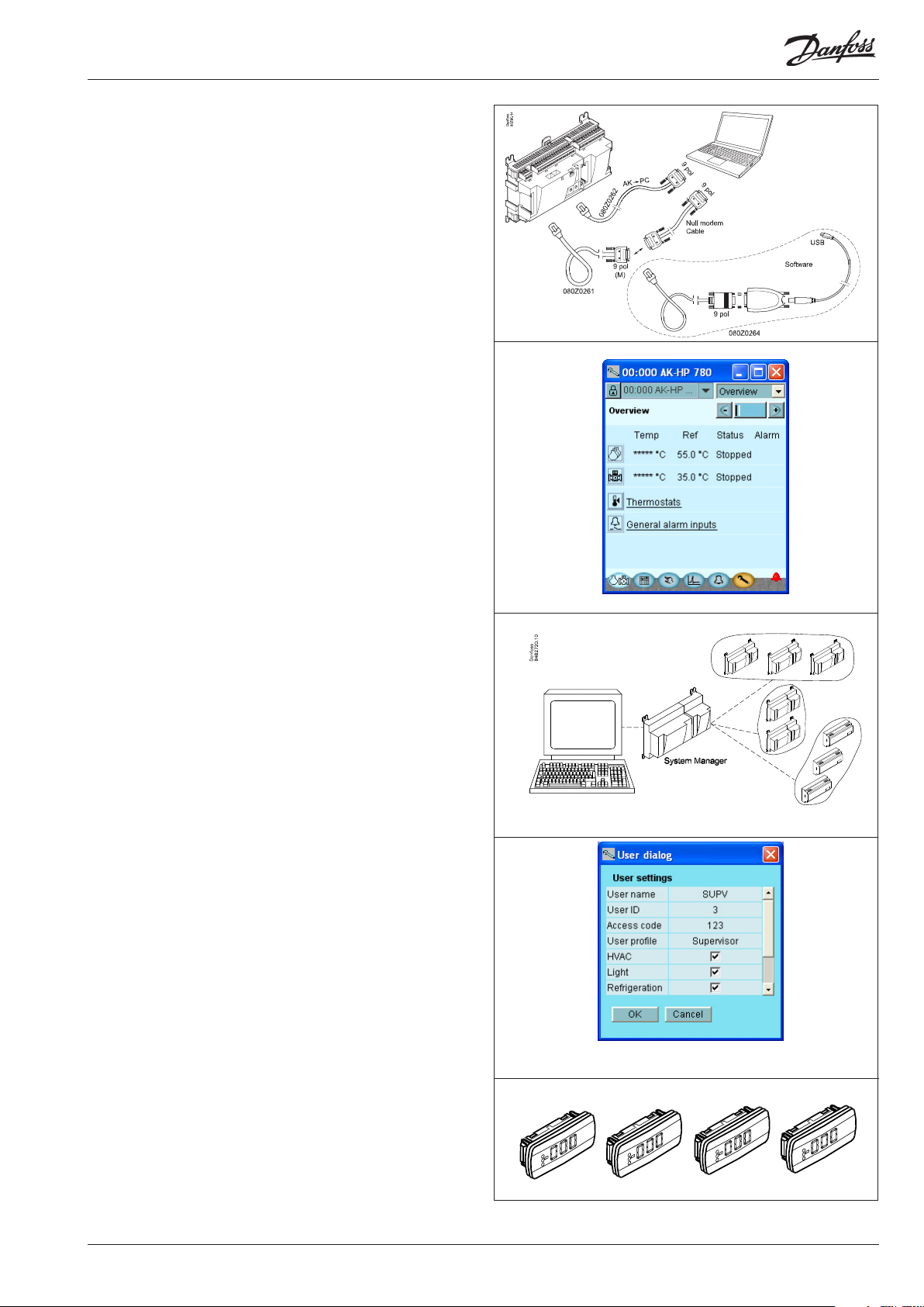
External display
An external display can be tted in order for S7 (receiver temperature), P0 (suction pressure) and Pd (discharge pressure) readings
to be displayed.
A total of 4 displays can be tted and with one setting it is possible to choose between the following readings: suction pressure,
suction pressure in temperature,, Sctrl, Ss, Sd, discharge pressure,
discharge pressure in temperature and S7.
AK-HP 780 Heat pump controller RS8GF202 © Danfoss 2015-08 5
Light-emitting diodes
A number of light-emitting diodes makes it possible to follow the
signals that are received and transmitted by the controller.
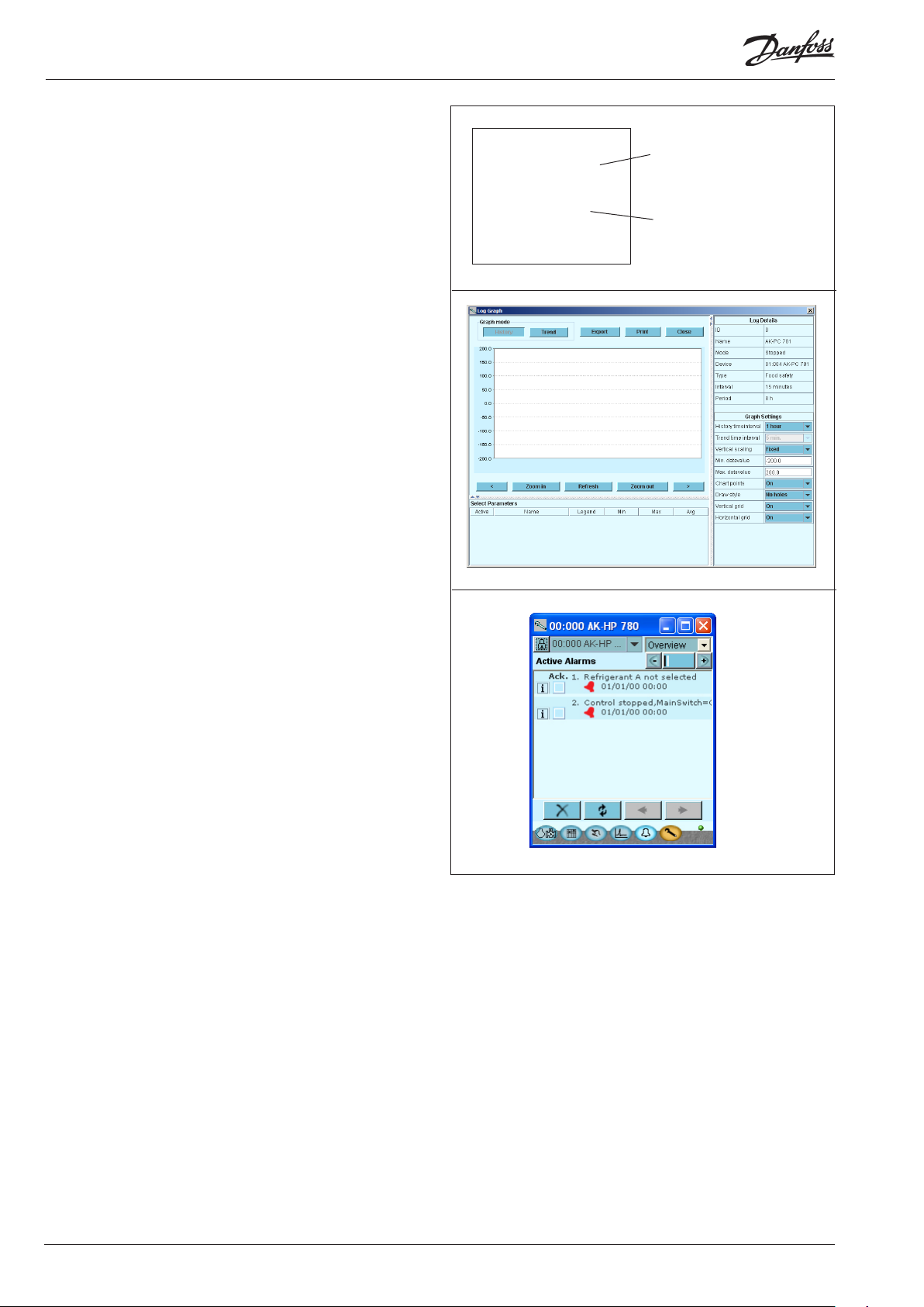
Log
From the log function you can dene the measurements you wish
to be shown.
The collected values can be printed, or you may export them to a
le. You can open the le in Excel.
If you are in a service situation you can show measurements in a
trend function. The measurements are then made real-time and
displayed instantly.
■ Power
■ Comm
■ DO1 ■ Status
■ DO2 ■ Service Tool
■ DO3 ■ LON
■ DO4
■ DO5 ■ Alarm
■ DO6
■ DO7
■ DO8 ■ Service Pin
Slow ash = OK
Quick ash = answer from gateway
Constantly ON = error
Constantly OFF = error
Flash = active alarm/not cancelled
Constant ON = Active alarm/cancelled
Alarm
The display gives you an overview of all active alarms. If you wish
to conrm that you have seen the alarm you can cross it o in the
acknowledge eld.
If you want to know more about a current alarm you can click on it
and obtain an information display on the screen.
A corresponding display exists for all earlier alarms. Here you can
upload information if you need further details about the alarm
history.
6 Heat pump controller RS8GF202 © Danfoss 2015-08 AK-HP 780

2. Design of a controller
This section describes how the controller is designed.
The controller in the system is based on a uniform connection
platform where any deviations from regulation to regulation is
determined by the used top part with a specic software and
by which input and output signals the relevant application will
require. If it is an application with few connections, the controller
module (top part with belonging bottom part) may be sucient.
If it is an application with many connections it will be necessary to
use the controller module plus one or more extension modules.
This section will give you a survey of possible connections plus
assistance in selecting the modules required by your actual
application.
AK-HP 780 Heat pump controller RS8GF202 © Danfoss 2015-08 7
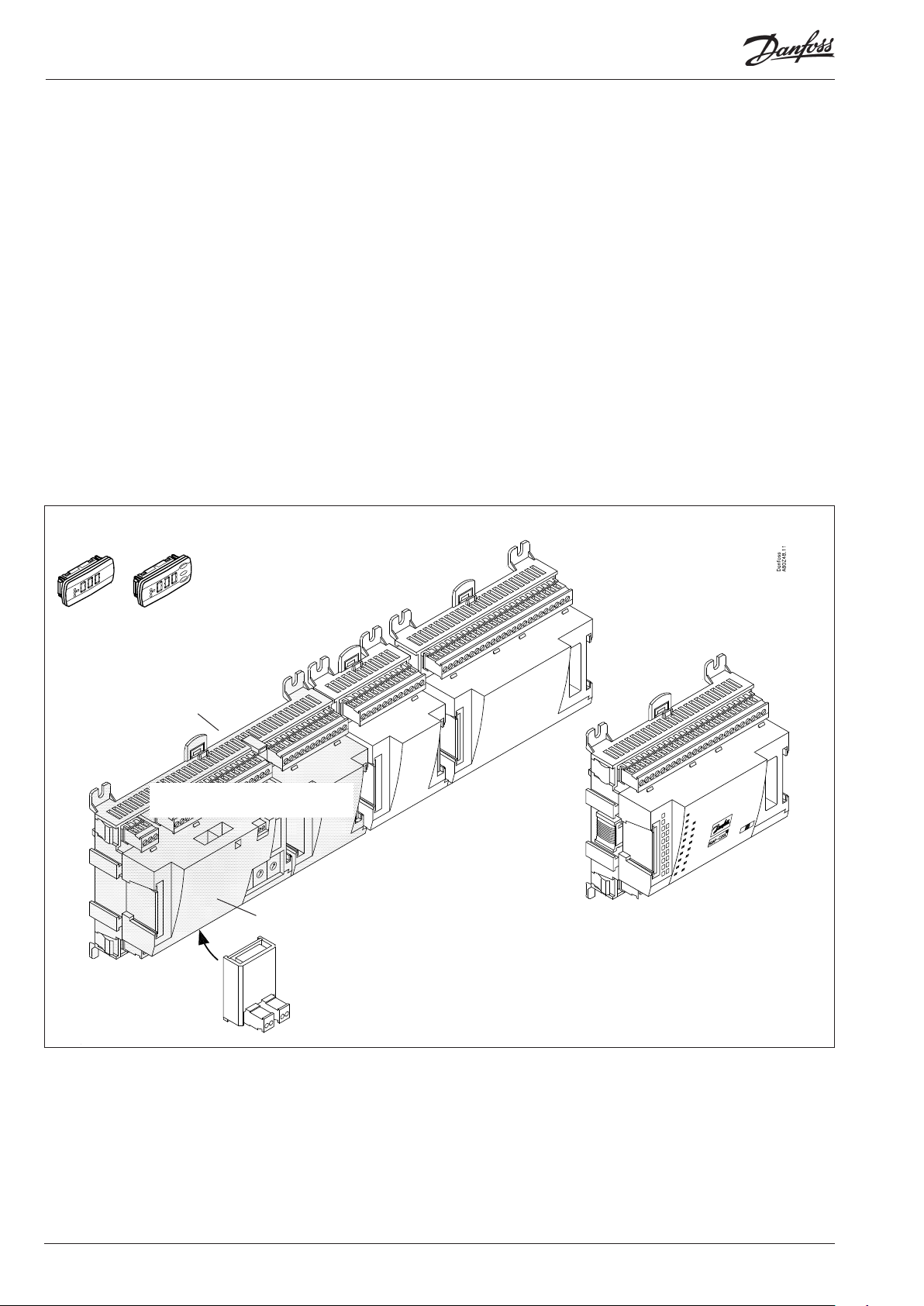
Module survey
• Controller module – capable of handling minor plant requirements.
• Extension modules. When the complexity becomes greater
and additional inputs or outputs are required, modules can be
attached to the controller. A plug on the side of the module will
transmit the supply voltage and data communication between
the modules.
• Top part
The upper part of the controller module contains the
intelligence. This is the unit where the regulation is dened and
where data communication is connected to other controllers in a
bigger network.
• Connection types
There are various types of inputs and outputs. One type may, for
example, receive signals from sensors and switches, another may
receive a voltage signal, and a third type may be outputs with
relays etc. The individual types are shown in the table below.
Extension module with
additional analog inputs
• Optional connection
When a regulation is planned (set up) it will generate a need for
a number of connections distributed on the mentioned types.
This connection must then be made on either the controller
module or an extension module. The only thing to be observed
is that the types must not be mixed (an analog input signal must
for instance not be connected to a digital input).
• Programming of connections
The controller must know where you connect the individual
input and output signals. This takes place in a later conguration where each individual connection is dened based on the
following principle:
- to which module
- at which point (”terminals”)
- what is connected (e.g. pressure transmitter/type/
pressure range)
Extension module with additional
relay outputs and additional
analog inputs.
External display for
suction pressure etc.
Bottom part
Controller with analog inputs and
relay outputs.
Top part
Extension module with
2x analog output signals
The module with additional relay outputs is
also available in a version where the top part
is provided with change-over switches so
that the relays can be overridden.
8 Heat pump controller RS8GF202 © Danfoss 2015-08 AK-HP 780
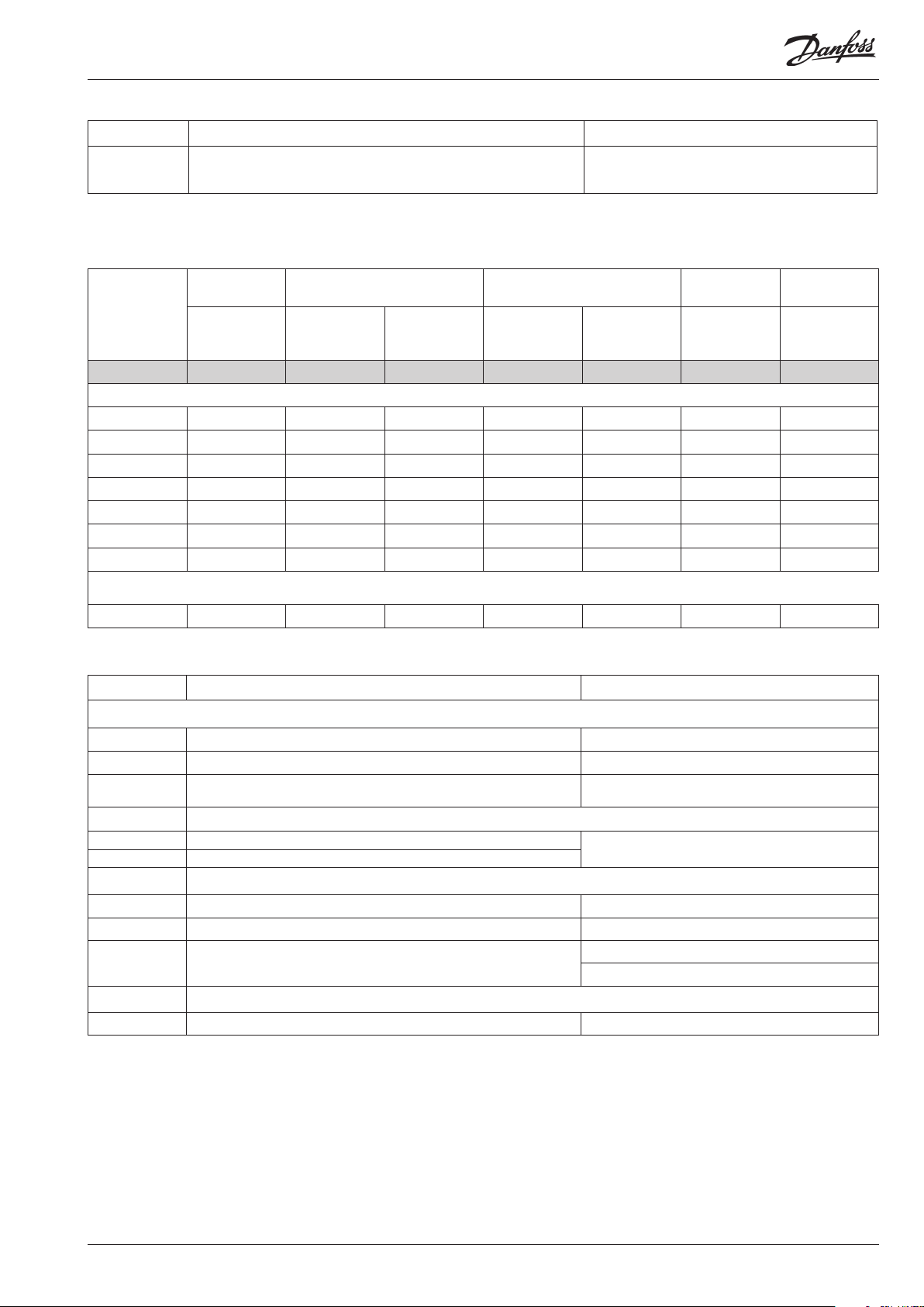
1. Controller
Type Function Application
AK-HP 780 Controller for heat pump control
Capacity control for heat pump operation.
Control of pump for hot water receiver.
Oil management
2. Extension modules and survey of inputs and outputs
Type Analog
inputs
For sensors, pressure transmitters
etc.
Controller 11 4 4 - - - -
Extension modules
AK-XM 101A 8
AK-XM 102A 8
AK-XM 102B 8
AK-XM 204A 8
AK-XM 204B 8 x
AK-XM 205A 8 8
AK-XM 205B 8 8 x
On/O outputs On/o supply voltage
Relay
(SPDT)
Solid state Low voltage
(DI signal)
(max. 80 V)
High voltage
(max. 260 V)
Analog
outputs
0-10 V d.c. For override of
Module with
switches
relay outputs
The following extension module can be placed on the PC board in the controller module. There is only room for one module.
AK-OB 110 2
3. AK operation and accessories
Type Function Application
Operation
AK-ST 500 Software for operation of AK controllers AK-operation
- Cable between PC and AK controller AK - Com port
-
Accessories Power supply module 230 V / 115 V to 24 V d.c.
AK-PS 075 18 VA
AK-PS 150 36 VA
Accessories External display that can be connected to the controller module. For showing, say, the receiver temperature
EKA 163B Display
EKA 164B Display with operation buttons
- Cable between display and controller
Accessories Real time clock for use in controllers that require a clock function, but are not wired with data communication.
AK-OB 101A Real time clock with battery backup. To be mounted in an AK controller
Cable between zero modem cable and AK controller /
Cable between PDA cable and AK controller
AK - RS 232
Supply for controller
Length = 2 m
Length = 6 m
On the following pages there is data specic to each module.
AK-HP 780 Heat pump controller RS8GF202 © Danfoss 2015-08 9
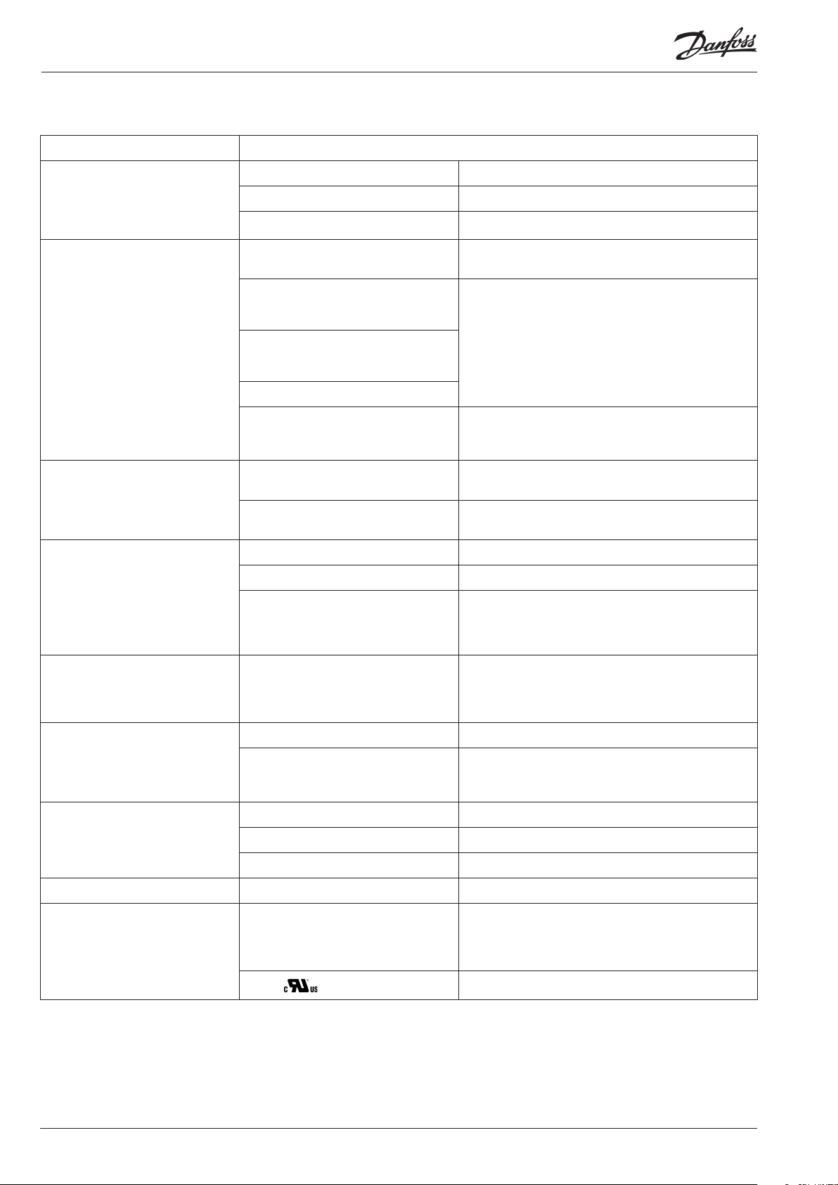
Common data for modules
Supply voltage 24 V d.c./a.c. +/- 20%
Power consumption AK-HP (controller) 8 VA
AK-XM 101, 102, 107 2 VA
AK-XM 204, 205 5 VA
Analog inputs Pt 1000 ohm /0°C Resolution: 0.1°C
Pressure transmitter type AKS 32R / AKS
2050
AKS 32 (1-5 V)
Other pressure transmitter:
Ratiometric signal
Min. and Max. pressure must be set
Voltage signal 0-10 V
Contact function (On/O ) On at R < 20 ohm
On/o supply voltage inputs Low voltage
Relay outputs
SPDT
0 / 80 V a.c./d.c.
High voltage
0 / 260 V a.c.
AC-1 (ohmic) 4 A
AC-15 (inductive) 3 A
U Min. 24 V
Accuracy: +/- 0.5°C
Resolution:1 mV
Accuracy +/- 10 mV
Max. connection of 5 pressure transmitters on one module
O at R > 2K ohm
(Gold -plated contacts not necessary)
O: U < 2 V
On: U > 10 V
O: U < 24 V
On: U > 80 V
Max. 230 V
Low and high voltage must not be connected to the same
output group
Solid state outputs Can be used for loads that are cut in and
out frequently, e.g. :
Oil valves
Ambient temperature During transport -40 to 70°C
During operation -20 to 55°C ,
Enclosure Material PC / ABS
Class IP10 , VBG 4
Mounting For mounting on panel wall or DIN rail
Weight with screw terminals Modules in 100- / 200- / controller-series Ca. 200 g / 500 g / 600 g
Approvals EU low voltage directive and EMC require-
ments are complied with
UL 873,
The mentioned data applies to all modules.
If data is specic, this is mentioned together with the module in question.
Capacitive load
The relays cannot be used for the direct connection of capacitive loads such
as LEDs and on/o control of EC motors.
All loads with a switch mode power supply must be connected with a suitable contactor or similar.
Max. 240 V a.c. , Min. 48 V a.c.
Max. 0,5 A,
Leak < 1 mA
Max. 1 AKV
0 to 95% RH (non condensing)
No shock inuences / vibrations
LVD tested according to EN 60730
EMC tested
Immunity according to EN 61000-6-2
Emission according to EN 61000-6-3
UL le number: E166834
10 Heat pump controller RS8GF202 © Danfoss 2015-08 AK-HP 780
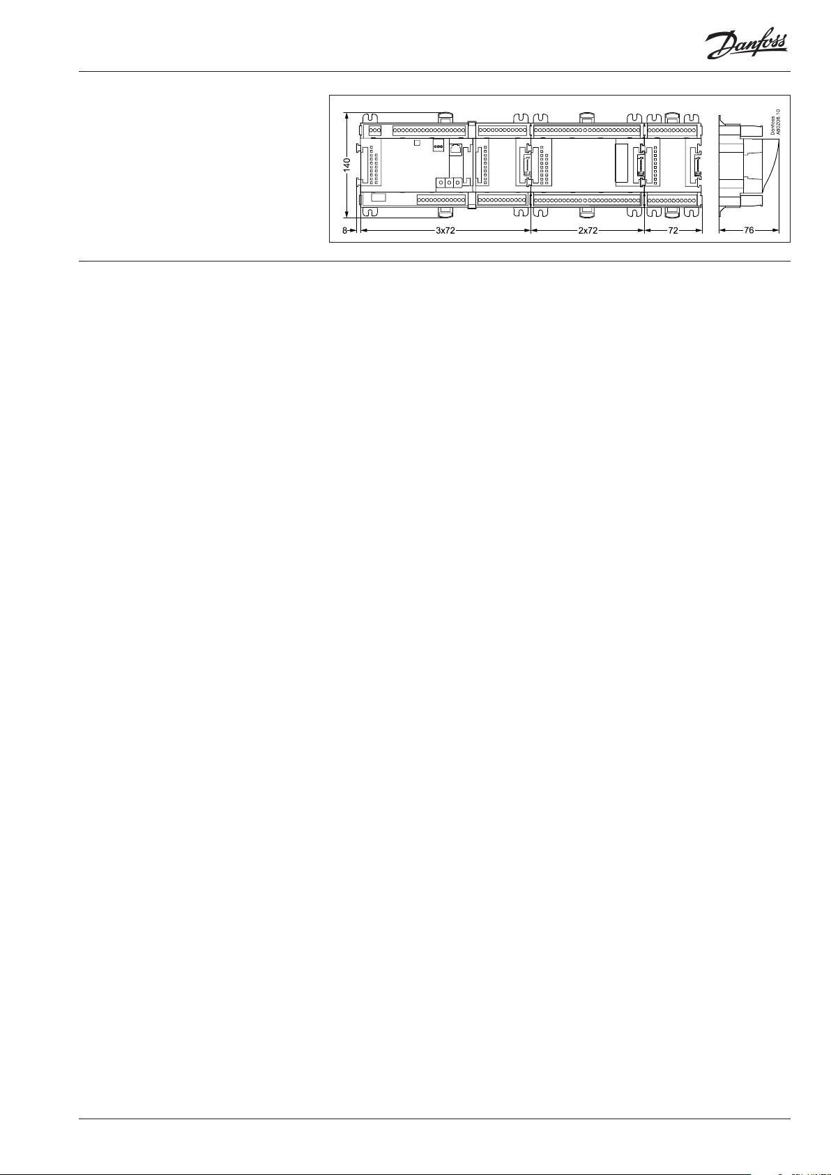
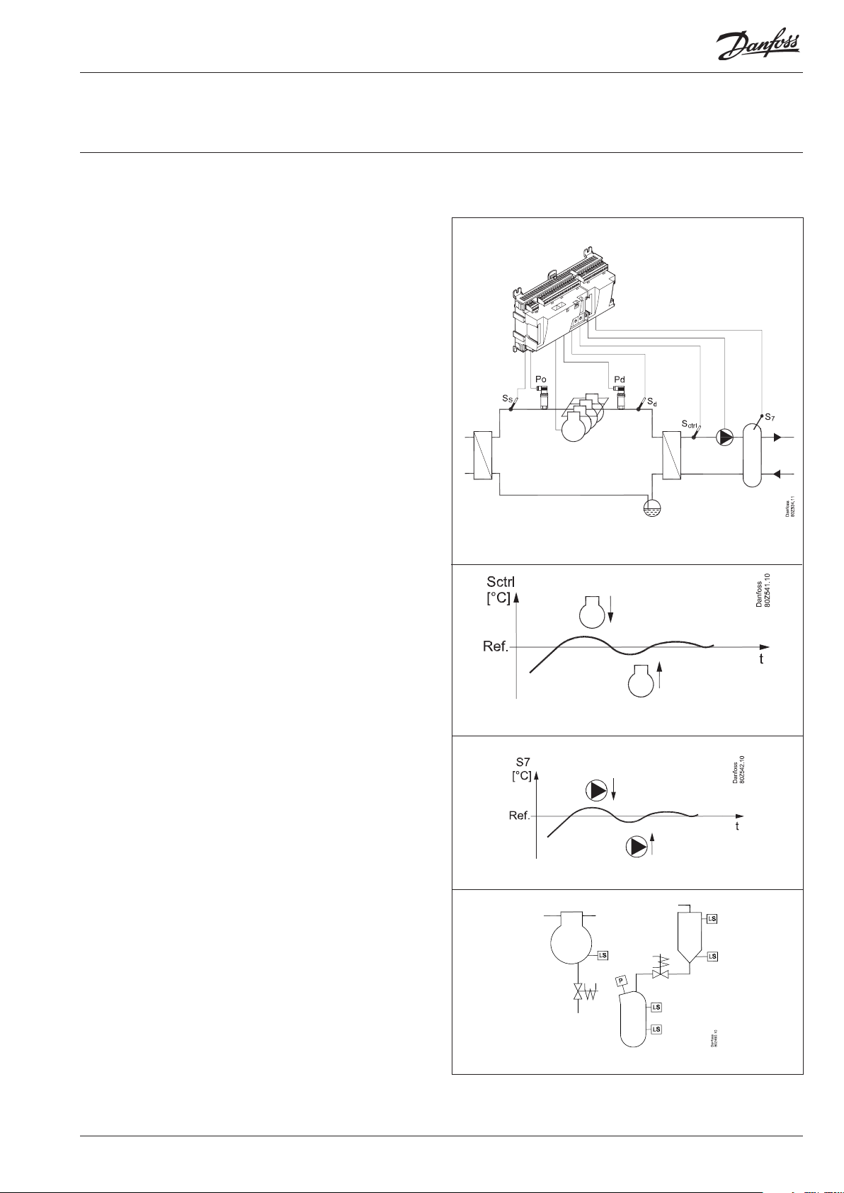
Dimensions
The module dimension is 72 mm.
Modules in the 100-series consist of one
module
Modules in the 200-series consist of two
modules
Controllers consist of three modules
The length of an aggregate unit = n x 72 + 8
AK-HP 780 Heat pump controller RS8GF202 © Danfoss 2015-08 11

Controller
Function
There are several controllers in the series. The function is
determined by the programmed software, but outwardly the
controllers are identical – they all have the same connection
possibilities:
11 analog inputs for sensors, pressure transmitters, voltage signals
and contact signals.
8 digital outputs, with 4 Solid state outputs and 4 relay outputs
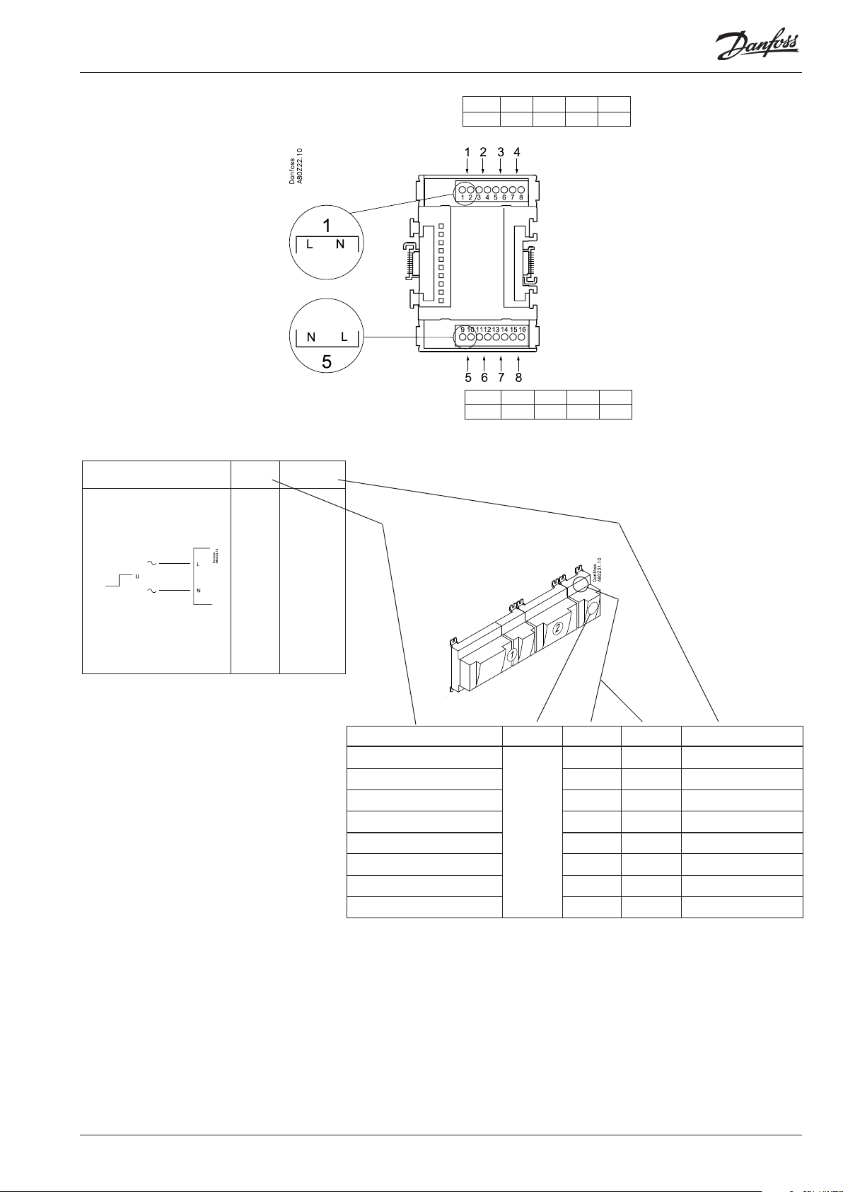
Supply voltage
24 V a.c. or d.c. to be connected to the controller.
The 24 V must not be retransmitted and used by other controllers
as it is not galvanically separated from inputs and outputs. In
other words, you must use a transformer for each controller. Class
II is required. The terminals must not be earthed.
The supply voltage to any extension modules is transmitted via
the plug on the right-hand side.
The size of the transformer is determined by the power
requirement of the total number of modules.
PIN
The supply voltage to a pressure transmitter can be taken either
from the 5 V output or from the 12 V output depending on
transmitter type.
Data communication
If the controller is to be included in a system, communication
must take place via the LON connection.
The installation has to be made as mentioned in the separate
instructions for LON communication.
Address setting
When the controller is connected to a gateway type AKA 245,
the controller’s address must be set between 1 and 119. (If it is a
system manager AK-SM .., then 1-999).
Service PIN
When the controller is connected to the data communication
cable the gateway must have knowledge of the new controller.
This is obtained by pushing the key PIN. The LED “Status” will ash
when the gateway sends an acceptance message.
Operation
The conguration operation of the controller must take place from
the software programme “Service Tool”. The program must be
installed on a PC, and the PC must be connected to the controller
via the network plug on the front of the unit.
Light-emitting diodes
There are two rows with LED’s. They mean:
Left row:
• Voltage supply to the controller
• Communication active with the bottom PC board (red = error)
• Status of outputs DO1 to DO8
Right row:
• Software status (slow ash = OK)
• Communication with Service Tool
• Communication on LON
• Alarm when LED ashes
- 3 LED’s that are not used
• “Service Pin” switch has been activated
Address
■ Power
■ Comm
■ DO1 ■ Status
■ DO2 ■ Service Tool
■ DO3 ■ LON
■ DO4
■ DO5 ■ Alarm
■ DO6
■ DO7
■ DO8 ■ Service Pin
Slow ash = OK
Quick ash = answer from gateway
Constantly ON = error
Constantly OFF = error
Flash = active alarm/not cancelled
Constant ON = Active alarm/cancelled
Keep the safety
distance!
Low and high
voltage must not
be connected to
the same output
group
A small module (option board) can be placed on the bottom part
of the controller. The module is described later in the document.
12 Heat pump controller RS8GF202 © Danfoss 2015-08 AK-HP 780
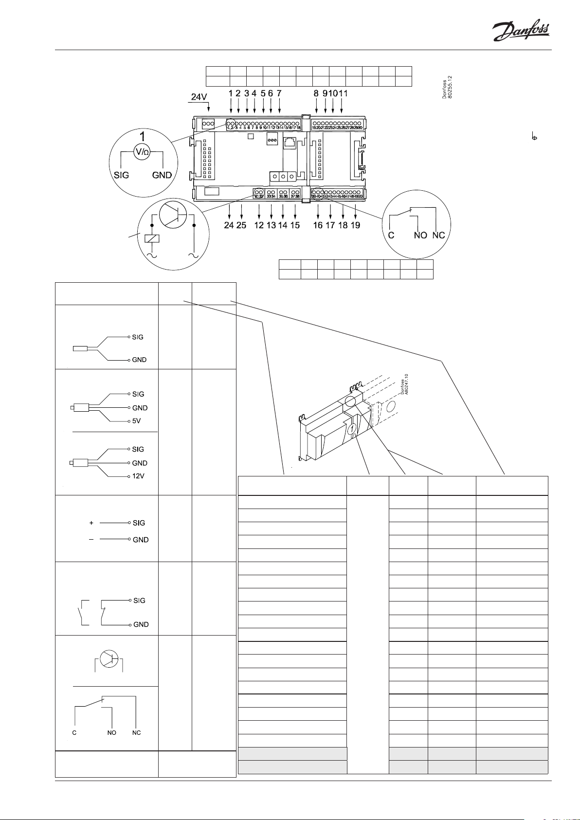
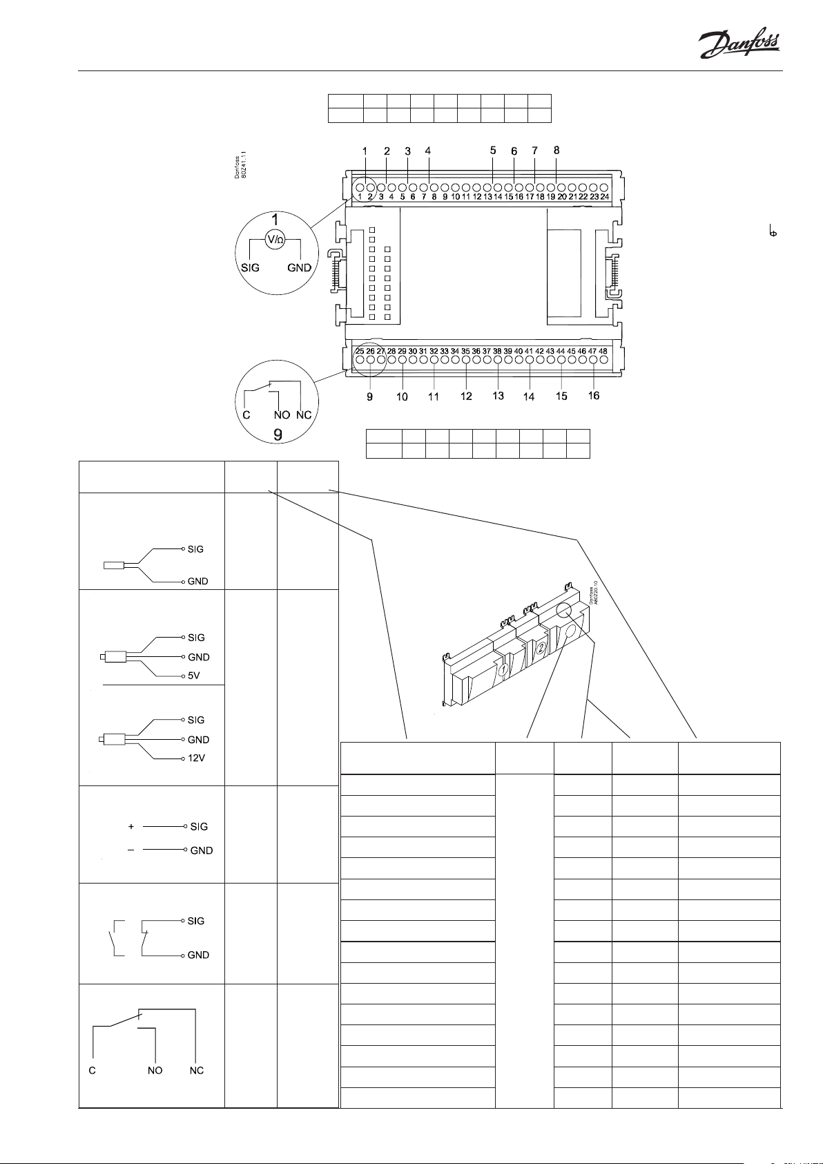
Point
Point 1 2 3 4 5 6 7 8 9 10 11
Type AI1 AI2 AI3 AI4 AI5 AI6 AI7 AI8 AI9 AI10 AI11
Terminal 15: 12 V
Terminal 16: 5 V
Terminal 27: 12 V
Terminal 28: 5 V
Analog
inputs
on 1 - 11
Solid state outputs
on 12 - 15
Relay or coil
fx 230 V a.c.
Signal Signal
S
Pt 1000 ohm/0°C
Sctrl
S7
Saux1
Saux2
SS
Sd
P
AKS 32R
3: Brown
2: Blue
1: Black
P0
Pd
Prec.
AKS 32
3: Brown
2: Black
1: Red
U
...
On/O Ext.
Main
switch
Day/
Night
Level
switch
DO
Comp 1
Comp 2
Pump
Alarm
Solenoid
valve
Option Board
Please see the signal
on the page with the
module.
24 and 25 used
only when "Option board tted"
type
Pt 1000
AKS 32R /
AKS 2050
-1 - xx bar
AKS 32
-1 - zz bar
0 - 5 V
0 - 10 V
Active at:
Closed
/
Open
Active at:
On
/
O
Point 12 13 14 15 16 17 18 19
Type DO1 DO2 DO3 DO4 DO5 DO6 DO7 DO8
Signal Module Point
1 (AI 1) 1 - 2
2 (AI 2) 3 - 4
3 (AI 3) 5 - 6
4 (AI 4) 7 - 8
5 (AI 5) 9 - 10
6 (AI 6) 11 - 12
7 (AI 7) 13 - 14
8 (AI 8) 19 - 20
9 (AI 9) 21 - 22
10 (AI 10) 23 - 24
1
11 (AI 11) 25 - 26
12 (DO 1) 31 - 32
13 (DO 2) 33 - 34
14 (DO 3) 35 - 36
15 (DO 4) 37 - 38
16 (DO 5) 39 - 40- 41
17 (DO6) 42 - 43 - 44
18 (DO7) 45 - 46 - 47
19 (DO8) 48 - 49 - 50
24 -
25 -
Terminal
17, 18, 29, 30:
(Cable screen)
Relay outputs on
16 - 19
Terminal
Signal type /
Active at
AK-HP 780 Heat pump controller RS8GF202 © Danfoss 2015-08 13

Extension module AK-XM 101A
Function
The module contains 8 analog inputs for sensors, pressure
transmitters, voltage signals and contact signals.
Supply voltage
The supply voltage to the module comes from the previous
module in the row.
Supply voltage to a pressure transmitter can be taken from either
the 5 V output or the 12 V output depending on transmitter type.
Light-emitting diodes
Only the two top LED’s are used. They indicate the following:
• Voltage supply to the module
• Communication with the controller is active (red = error)
14 Heat pump controller RS8GF202 © Danfoss 2015-08 AK-HP 780
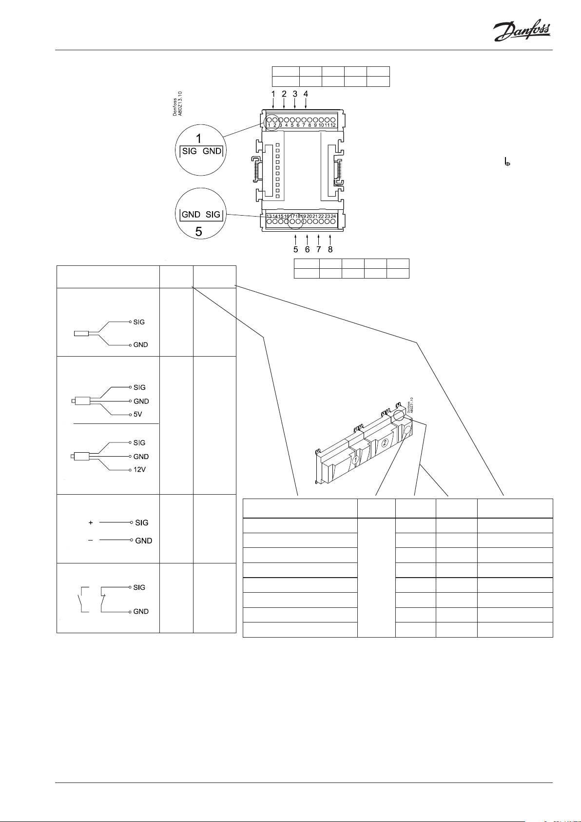
Point
Point 1 2 3 4
Type AI1 AI2 AI3 AI4
Terminal 9: 12 V
Terminal 10: 5 V
S
Pt 1000 ohm/0°C
P
AKS 32R
AKS 32
At the top the
signal input is
the left of the
two terminals.
At the bottom
the signal input
is the right of the
two terminals.
3: Brown
2: Blue
1: Black
3: Brown
2: Black
1: Red
Signal Signal
type
Sctrl
S7
Saux1
Pt 1000
Saux2
SS
Sd
AKS 32R /
P0
Pd
Prec.
AKS 2050
-1 - xx bar
AKS 32
-1 - zz bar
Terminal 15: 5 V
Terminal 16: 12 V
Terminal
11, 12, 13, 14:
(Cable screen)
Point 5 6 7 8
Type AI5 AI6 AI7 AI8
U
On/O
...
Ext.
Main
switch
Day/
Night
Level
switch
0 - 5 V
0 - 10 V
Active at:
Closed
/
Open
Signal Module Point
1 (AI 1) 1 - 2
2 (AI 2) 3 - 4
3 (AI 3) 5 - 6
4 (AI 4) 7 - 8
5 (AI 5) 17 - 18
6 (AI 6) 19 - 20
7 (AI 7) 21 - 22
8 (AI 8) 23 - 24
Terminal
Signal type /
Active at
AK-HP 780 Heat pump controller RS8GF202 © Danfoss 2015-08 15
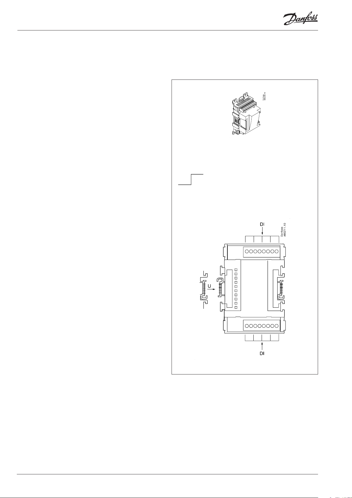
Extension module AK-XM 102A / AK-XM 102B
Function
The module contains 8 inputs for on/o voltage signals.
Signal
AK-XM 102A is for low voltage signals.
AK-XM 102B is for high voltage signals.
Supply voltage
The supply voltage to the module comes from the previous
module in the row.
Light-emitting diodes
They indicate:
• Voltage supply to the module
• Communication with the controller is active (red = error)
• Status of the individual inputs 1 to 8 (when lit = voltage)
AK-XM 102A
Max. 24 V
On/O:
On: DI > 10 V a.c.
O: DI < 2 V a.c.
AK-XM 102B
Max. 230 V
On/O:
On: DI > 80 V a.c.
O: DI < 24 V a.c.
16 Heat pump controller RS8GF202 © Danfoss 2015-08 AK-HP 780
Point
DI
AK-XM 102A: Max. 24 V
AK-XM 102B: Max. 230 V
Signal Active at
Ext.
Main
switch
Day/
Night
Comp.
safety 1
Comp.
safety 2
Level
switch
Closed
(voltage on)
/
Open
(voltage o)
Point 1 2 3 4
Type DI1 DI2 DI3 DI4
Point 5 6 7 8
Type DI5 DI6 DI7 DI8
Signal Module Point Terminal Active at
1 (DI 1) 1 - 2
2 (DI 2) 3 - 4
3 (DI 3) 5 - 6
4 (DI 4) 7 - 8
5 (DI 5) 9 - 10
6 (DI 6) 11 - 12
7 (DI 7) 13 - 14
8 (DI 8) 15 - 16
AK-HP 780 Heat pump controller RS8GF202 © Danfoss 2015-08 17
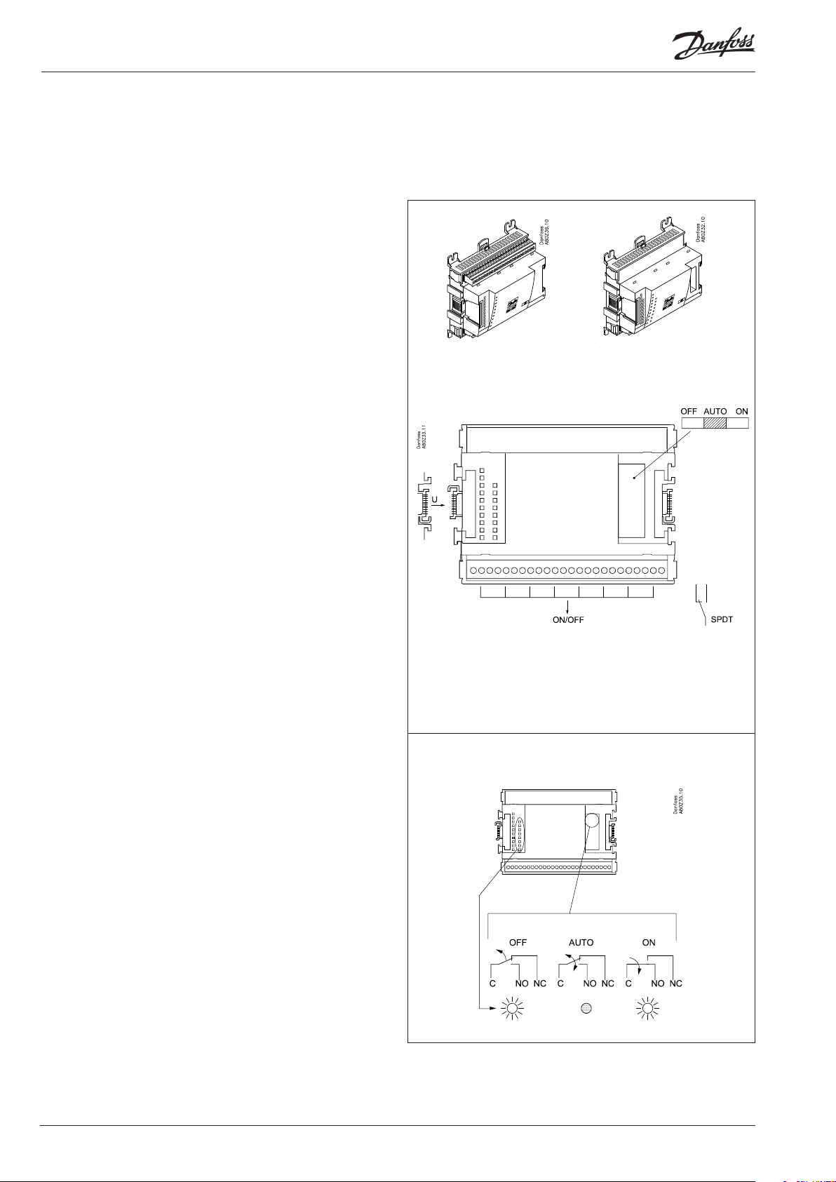
Extension module AK-XM 204A / AK-XM 204B
Function
The module contains 8 relay outputs.
Supply voltage
The supply voltage to the module comes from the previous
module in the row.
AK-XM 204B only
Override of relay
Eight change-over switches at the front make it possible to
override the relay’s function.
Either to position OFF or ON.
In position Auto the controller carries out the control.
Light-emitting diodes
There are two rows with LED’s. They indicate the following:
Left row:
• Voltage supply to the controller
• Communication active with the bottom PC board (red = error)
• Status of outputs DO1 to DO8
Right row: (AK-XM 204B only):
• Override of relays
ON = override
OFF = no override
AK-XM 204A AK-XM 204B
Fuses
Behind the upper part there is a fuse for each output.
Note
If the changeovers are used to override the compressor operation,
it is necessary to wire a safety relay into the circuit for oil management. Without this safety relay, the controller will fail to stop the
compressor if it should run out of oil. See Regulating functions.
Max. 230 V
AC-1: max. 4 A (ohmic)
AC-15: max. 3 A (Inductive)
AK-XM 204B
Override of relay
Keep the safety distance!
Low and high voltage
must not be connected to
the same output group
18 Heat pump controller RS8GF202 © Danfoss 2015-08 AK-HP 780
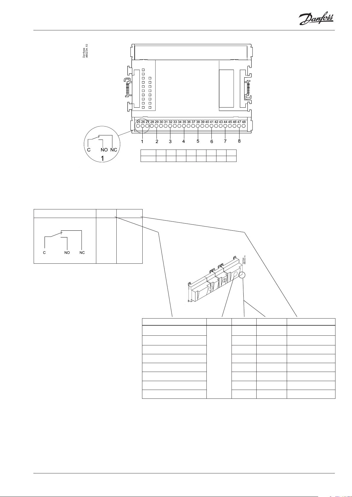
Point
DO
Signal Active at
Comp. 1
Comp. 2
Pump
Alarm
Solenoid
valve
On
/
O
Point 1 2 3 4 5 6 7 8
Type DO1 DO2 DO3 DO4 DO5 DO6 DO7 DO8
Signal Module Point Terminal Active at
1 (DO 1) 25 - 27
2 (DO 2) 28 - 30
3 (DO 3) 31 - 33
4 (DO 4) 34 -36
5 (DO 5) 37 - 39
6 (DO 6) 40 - 41 - 42
7 (DO 7) 43 - 44 - 45
8 (DO 8) 46 - 47 - 48
AK-HP 780 Heat pump controller RS8GF202 © Danfoss 2015-08 19
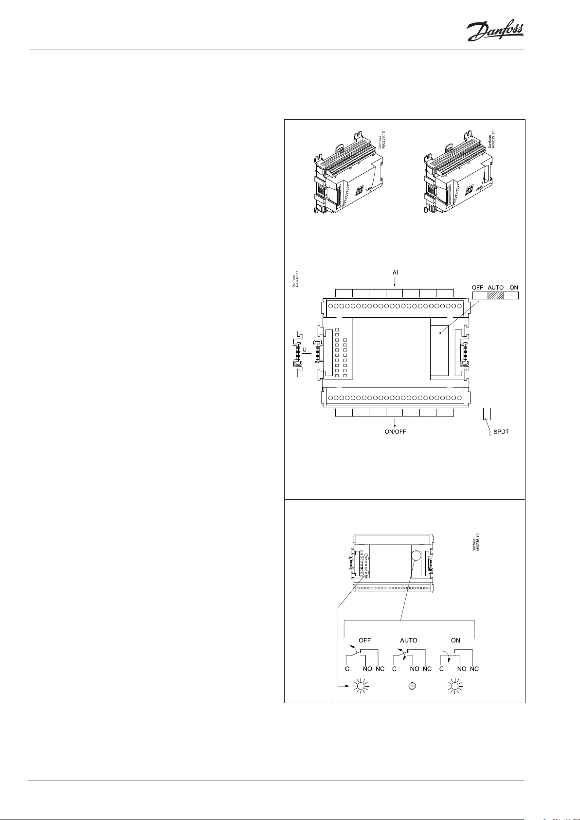
Extension module AK-XM 205A / AK-XM 205B
Function
The module contains:
8 analog inputs for sensors, pressure transmitters, voltage signals
and contact signals.
8 relay outputs.
Supply voltage
The supply voltage to the module comes from the previous
module in the row.
AK-XM 205B only
Override of relay
Eight change-over switches at the front make it possible to
override the relay’s function.
Either to position OFF or ON.
In position Auto the controller carries out the control.
Light-emitting diodes
There are two rows with LED’s. They mean:
Left row:
• Voltage supply to the controller
• Communication active with the bottom PC board (red = error)
• Status of outputs DO1 to DO8
Right row: (AK-XM 205B only):
• Override of relays
ON = override
OFF = no override
AK-XM 205A AK-XM 205B
max. 10 V
Fuses
Behind the upper part there is a fuse for each output.
Note
If the changeovers are used to override the compressor operation,
it is necessary to wire a safety relay into the circuit for oil management. Without this safety relay, the controller will fail to stop the
compressor if it should run out of oil. See Regulating functions.
Max. 230 V
AC-1: max. 4 A (ohmic)
AC-15: max. 3 A (Inductive)
AK-XM 205B
Override of relay
Keep the safety distance!
Low and high voltage
must not be connected to
the same output group
20 Heat pump controller RS8GF202 © Danfoss 2015-08 AK-HP 780
Point
S
Pt 1000 ohm/0°C
Signal Signal
type
Sctrl
S7
Saux1
Pt 1000
Saux2
SS
Sd
Point 1 2 3 4 5 6 7 8
Type AI1 AI2 AI3 AI4 AI5 AI6 AI7 AI8
Terminal 9: 12 V
Terminal 10: 5 V
Terminal 21: 12 V
Terminal 22: 5 V
Terminal 11, 12, 23, 24 :
(Cable screen)
Point 9 10 11 12 13 14 15 16
Type DO1 DO2 DO3 DO4 DO5 DO6 DO7 DO8
P
AKS 32R
AKS 32
U
On/O
DO
3: Brown
2: Blue
1: Black
3: Brown
2: Black
1: Red
P0
Pd
Prec.
...
Ext. Main
switch
Day/
Night
Level
switch
Comp 1
Comp 2
Pump
Alarm
Solenoid
valve
AKS 32R /
AKS 2050
-1 - xx bar
AKS 32
-1 - zz bar
0 - 5 V
0 - 10 V
Active at:
Closed
/
Open
Active at:
on
/
O
Signal Module Point
1 (AI 1) 1 - 2
2 (AI 2) 3 - 4
3 (AI 3) 5 - 6
4 (AI 4) 7 - 8
5 (AI 5) 13 - 14
6 (AI 6) 15 - 16
7 (AI 7) 17 - 18
8 (AI 8) 19 -20
9 (DO 1) 25 - 26 - 27
10 (DO 2) 28 - 29 - 30
11 (DO 3) 31 - 30 - 33
12 (DO 4) 34 - 35 - 36
13 (DO 5) 37 - 36 - 39
14 (DO6) 40 - 41 - 42
15 (DO7) 43 - 44 - 45
16 (DO8) 46 - 47 - 48
Terminal
Signal type /
Active at
AK-HP 780 Heat pump controller RS8GF202 © Danfoss 2015-08 21
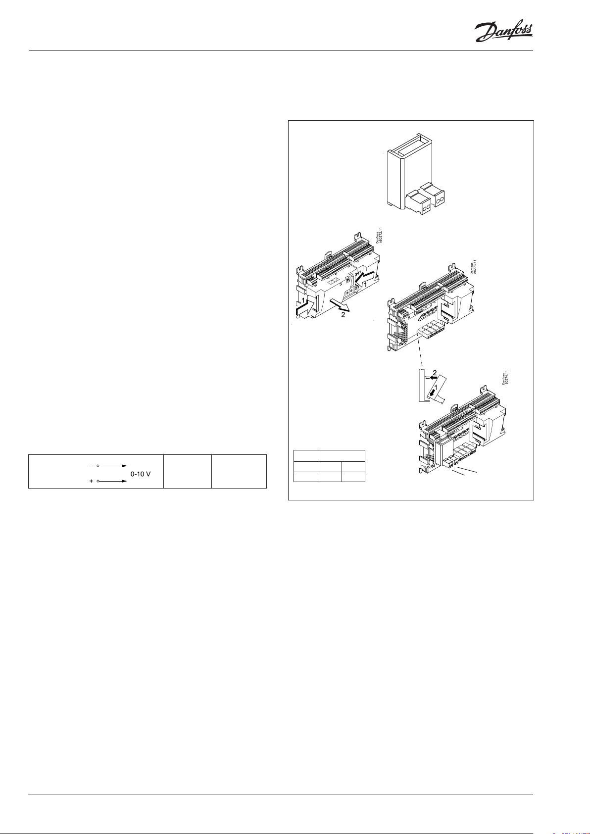
Extension module AK-OB 110
Function
The module contains two analog voltage outputs of 0 – 10 V.
Supply voltage
The supply voltage to the module comes from the controller
module.
Placing
The module is placed on the PC board in the controller module.
Point
The two outputs have points 24 and 25. They are shown on the
earlier page where the controller is also mentioned.
Max. load
I < 2.5 mA
R > 4 kohm
AO
AO 0 - 10 V
Module
Point 24 25
Type AO1 AO2
1
AO2
AO1
22 Heat pump controller RS8GF202 © Danfoss 2015-08 AK-HP 780
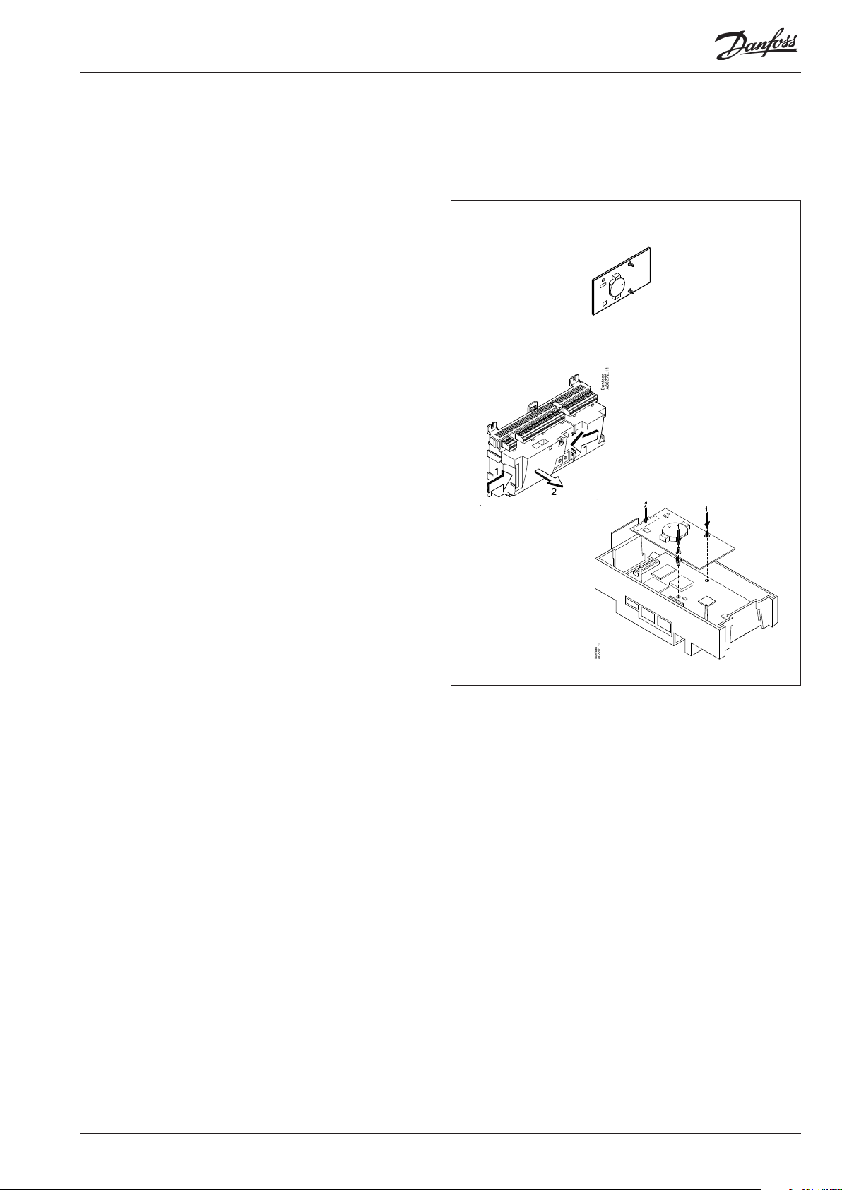
Extension module AK-OB 101A
Function
The module is a real time clock module with battery backup.
The module can be used in controllers that are not linked up in
a data communication unit together with other controllers. The
module is used here if the controller needs battery backup for the
following functions
• Clock function
• Fixed times for day/night change-over
• Saving of alarm log in case of power failure
• Saving of temperature log in case of power failure
Connection
The module is provided with plug connection.
Placing
The module is placed on the PC board inside the top part.
Point
No point for a clock module to be dened – just connect it.
Working life of the battery
The working life of the battery is several years – even if there are
frequent power failures.
An alarm is generated when the battery has to be replaced.
After the alarm there are still several months of operating hours
left in the battery.
AK-HP 780 Heat pump controller RS8GF202 © Danfoss 2015-08 23
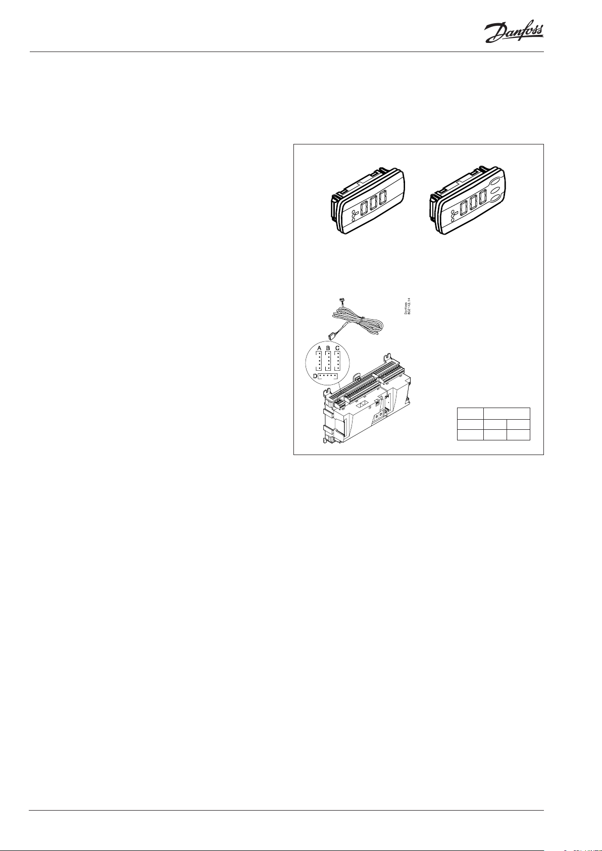
Extension module EKA 163B / EKA 164B
Function
Display of important measurements from the controller, e.g. re-
ceiver temperature, suction pressure or discharge gas pressure.
Setting of the individual functions can be performed by using the
display with control buttons.
It is the controller used that determines the measurements and
settings that can occur.
Connection
The extension module is connected to the controller module via
a cable with plug connections. You have to use one cable per
module. The cable is supplied in various lengths.
Both types of display (with or without control buttons) can be
connected to either display output A, B, C and D.
A: P0. Suction pressure in °C.
B: Pc. Condensing pressure in °C.
When the controller starts up, the display will show which output
is connected. - - 1 = output A, - - 2 = output B, etc.
Placing
The extension module can be placed at a distance of up to 15 m
from the controller module.
EKA 163B EKA 164B
Point
No point has to be dened for a display module – you simply connect it.
Module
Point - -
Type - -
1
24 Heat pump controller RS8GF202 © Danfoss 2015-08 AK-HP 780
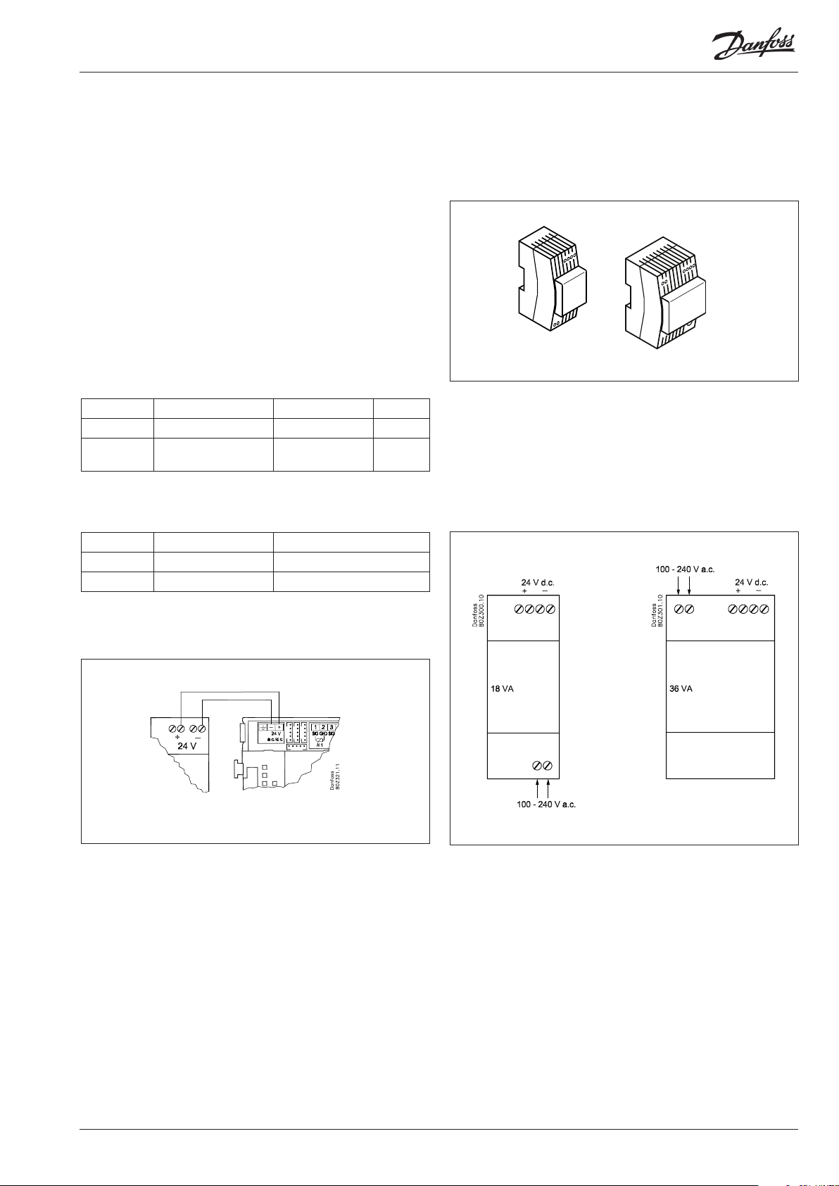
Power supply module AK-PS 075 / 150
Function
24 V supply for controller.
Supply voltage
230 V a.c or 115 V a.c. (from 100 V a.c. to 240 V a.c.)
Placing
On DIN-rail
Eect
Type Output tension Output current Power
AK-PS 075 24 V d.c. 0.75 A 18 VA
AK-PS 150 24 V d.c.
(adjustable)
1.5 A 36 VA
Dimension
Type High Width
AK-PS 075 90 mm 36 mm
AK-PS 150 90 mm 54 mm
Supply to a controller
Connections
AK-PS 075
AK-PS 150
AK-HP 780 Heat pump controller RS8GF202 © Danfoss 2015-08 25

Preface to design
Be aware of the following when the number of extension modules
is being planned. A signal may have to be changed, so that an
additional module may be avoided.
• An ON/OFF signal can be received in two ways. Either as a
contact signal on an analog input or as voltage on a low or highvoltage module.
• An ON/OFF output signal can be given in two ways. Either with a
relay switch or with solid state. The primary dierence is the permitted load and that the relay switch contains a cutout switch.
Mentioned below is a number of functions and connections
that may have to be considered when a regulation has to be
planned. There are more functions in the controller than the ones
mentioned here, but those mentioned have been included in
order that the need for connections can be established.
Functions
Clock function
Clock function and change-over between summer time and
winter time are contained in the controller.
The clock is zeroset when there is power failure.
The clock’s setting is maintained if the controller is linked up in a
network with a gateway, a system manager or a clock module can
be mounted in the controller.
Start/stop of regulation
Regulation can be started and stopped via the software. External
start/stop can also be connected.
Alarm function
If the alarm is to be sent to a signal transmitter, a relay output will
have to be used.
Extra temperature sensors and pressure sensors
If additional measurements have to be carried out beyond the
regulation, sensors can be connected to the analog inputs.
Forced control
The software contains a forced control option. If an extension
module with relay outputs is used, the module’s top part can
be with change-over switches – switches that can override the
individual relays into either OFF or ON position.
Wiring should be done with a safety relay. See Regulating functions.
Data communication
The controller module has terminals for LON data communication.
The requirements to the installation are described in a separate
document.
26 Heat pump controller RS8GF202 © Danfoss 2015-08 AK-HP 780
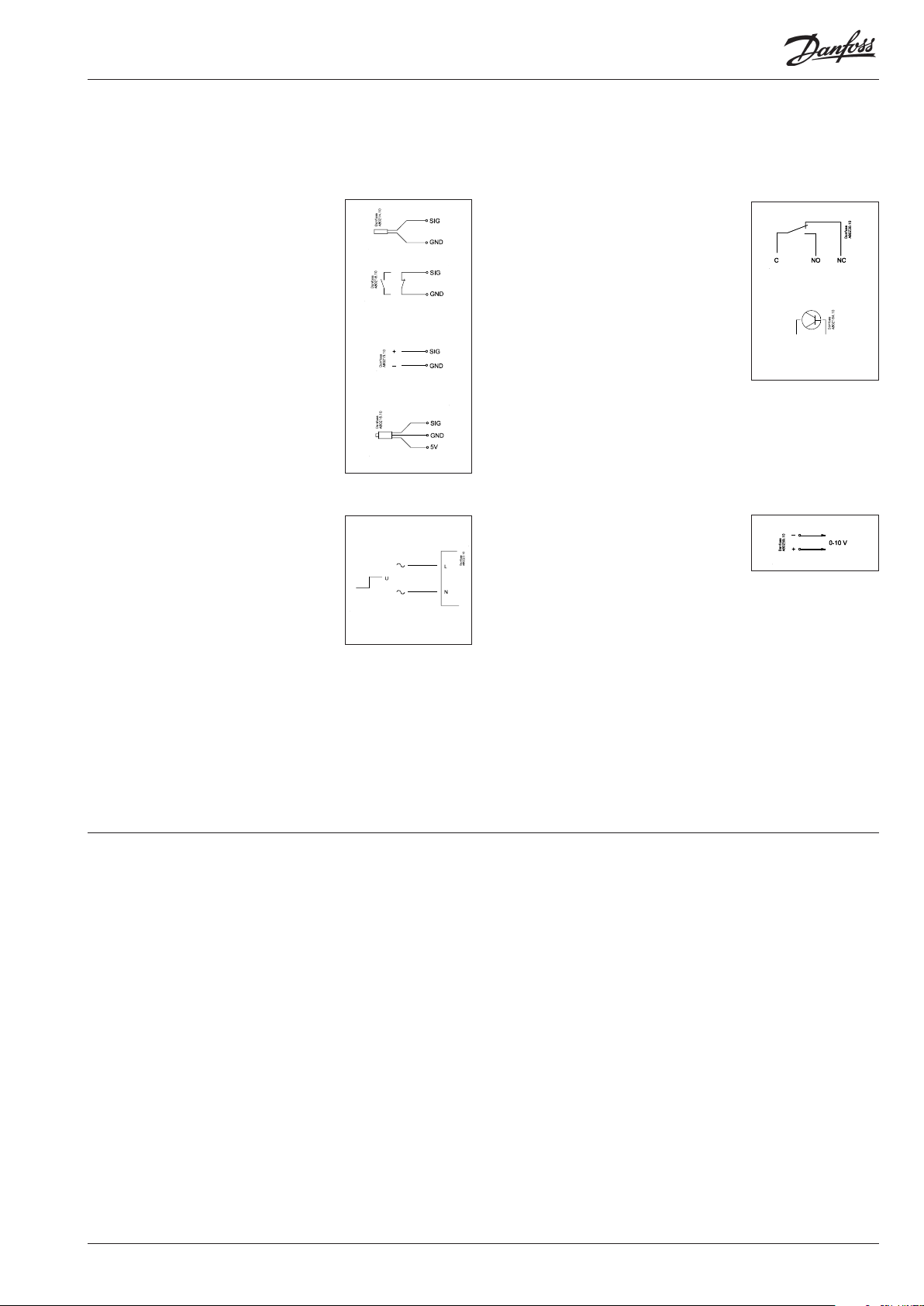
Connections
In principle there are the following types of connections:
Analog inputs ”AI”
This signal must be connected to two
terminals.
Signals can be received from the following
sources:
• Temperature signal from Pt 1000 ohm
temperature sensor
• Contact signal where the input is shortcircuited or ”opened”, respectively
• Voltage signal from 0 to 10 V
• Signal from pressure transmitter AKS 32,
AKS 32R or AKS 2050
The supply voltage is supplied from the
module’s terminal board where there is
both a 5 V supply and a 12 V supply.
When programming the pressure
transmitter’s pressure range must be set.
ON/OFF voltage inputs ”DI”
This signal must be connected to two
terminals.
• The signal must have two levels, either 0 V
or ”voltage” on the input.
There are two dierent extension
modules for this signal type:
- low-voltage signals, e.g. 24 V
- high-voltage signals, e.g. 230 V
ON/OFF output signals ”DO”
There are two types, as follows:
• Relay outputs
All relay outputs are with change-over
relay so that the required function can be
obtained when the controller is without
voltage.
• Solid state outputs
Reserved for AKV valves, but output can
cut an external relay in and out, as with a
relay output.
The output is only found on the
controller module.
When programming the function must be set:
• Active when the output is activated
• Active when the output is not activated.
Analog output signal ”AO”
This signal is to be used if a control signal is
to be transmitted to an external unit, e.g. a
frequency converter.
When programming the signal range must
be dened: 0-5 V, 1-5 V, 0-10 V or 2-10 V.
When programming the function must be set:
• Active when the input is without voltage
• Active when voltage is applied to the
input.
Limitations
As the system is very exible regarding the number of connected
units you must check whether your selection complies with the
few limitations there are.
The complexity of the controller is determined by the software,
the size of the processor, and the size of the memory. It provides
the controller with a certain number of connections from which
data can be downloaded, and others where coupling with relays
can be performed.
✔ The sum of connections cannot exceed 100
✔ The number of extension modules must be limited so that the
total power will not exceed 32 VA (including controller).
✔ No more than 5 pressure transmitters may be connected to one
controller module.
✔ No more than 5 pressure transmitters may be connected to one
extension module.
AK-HP 780 Heat pump controller RS8GF202 © Danfoss 2015-08 27
Design of a compressor and pump control
Procedure:
1. Make a sketch of the system in question
2. Check that the controller’s functions cover the required
application
3. Consider the connections to be made
4. Use the planning table. / Note down the number of connections
./ add up
5. Are there enough connections on the controller module? – If
not, can they be obtained by changing an ON/OFF input signal
from voltage signal to contact signal, or will an extension
module be required?
6. Decide which extension modules are to be used
7. Check that the limitations are observed
8. Calculate the total length of modules
9. The modules are linked together
10. The connection sites are established
11. Draw a connection diagram or a key diagram
12. Size of supply voltage/transformer
1
Follow these 12
steps
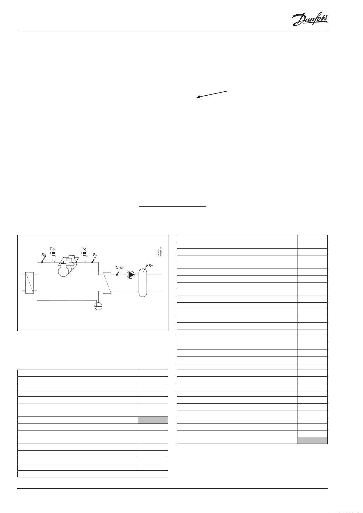
Sketch
Make a sketch of the system in question.
2
Functions
Application
Regulation of a compressor group x
Regulation of receiver temperature x
Regulation of compressor capacity
Regulation sensor = Sctrl x
PI-regulation x
Max. number of compressor steps 8
Max. number of unloaders each compressor 3
Identical compressor capacities x
Dierent compressor capacities x
Sequential operation (rst in / last out) x
Speed regulation of 1 compressor or 2 parallel compressors x
Run time equalisation x
Min. restart time x
Min. On-time x
AK-HP 780
Oil management
Oil injection in compressor. Shared or individual x
Receiver pressure control x
Monitoring of oil level in receiver x
Management of oil level in oil separator x
Reset of oil management x
Cutout of compressors at oil failure x
Safety relays during forced compressor control x
Temperature reference for Sctrl
Override via “night setback” x
Override via "0 -10 V signal" x
Regulation of receiver temperature
Regulation sensor. = S7 x
On/o control of pump x
Speed regulation of pump x
Safety functions
Min. suction pressure x
Max. suction pressure x
Max. discharge pressure x
Max. discharge gas temperature x
Min. / Max. superheat x
Safety monitoring of compressors x
Common high pressure monitoring of compressors x
General alarm functions with time delay 10
Miscellaneous
Extra sensors 7
Option for connection of separate display 4
Separate thermostat functions 5
Separate pressostat functions 5
Separate voltage measurements 5
Max. input and output 100
28 Heat pump controller RS8GF202 © Danfoss 2015-08 AK-HP 780

A bit more about the functions
3
Compressor
Regulation of up to 8 compressors. And up to 3 unloaders each
compressor.
Compressor No. 1 or 2 can be speed-regulated.
A signal is required from pressure transmitters P0 and Pd.
A signal is required from temperature sensors Ss and Sd.
P0 is also used to protect against a too low pressure.
Pd is also used to protect against a too high pressure.
Temperature reference
Sctrl is used as a regulating sensor.
The cut in and cut out of the compressors is determined by the
measured temperature.
Receiver
S7 is used as a regulating sensor.
One pump can be controlled based on the measured signal. Signals can be delivered so that the pump can be speed-controlled.
Speed regulation
The function requires an analog output module.
A relay output may be used for start/stop of the speed regulation.
Safety circuit
If signals are to be received from one or more parts of a safety
circuit, each signal must be connected to an ON/OFF input.
Day/night signal for lowering the temperature reference Sctrl.
The clock function can be used, but an external ON/OFF signal
may be used instead.
Separate thermostat and pressure control functions
A number of thermostats can be used according to your wishes.
The function requires a sensor signal and a relay output. In the
controller there are settings for cutin and cutout values. An associated alarm function may also be used.
Separate voltage measurements
A number of voltage measurements can be used according to
your wishes. The signal can for example be 0-10 V. The function
requires a voltage signal and a relay output. In the controller there
are settings for cutin and cutout values. An associated alarm function may also be used.
If you want to know more about the functions, go to
chapter 5.
Connections
Here is a survey of the possible connections. The texts can be read
in context with the table on page 31.
Analog inputs
Temperature sensors
• Sctrl
Must always be used as a regulating sensor for compressor
regulation.
• Ss (suction gas temperature)
Must always be used.
• Sd (discharge gas temperature)
Must always be used.
• S7 (receiver temperature)
Must always be used for regulation sensor for pump control.
• Saux (1-5), any extra temperature sensors
Up to ve additional sensors for monitoring and data collection may be connected. These sensors can be used for general
thermostat functions.
Pressure transmitters
• P0 Suction Pressure
Must always be used.
• Pd Discharge pressure
Must always be used.
• Prec. Oil receiver pressure. Must be used for oil receiver pressure
regulation.
• Paux (1-5)
Up to 5 extra pressure transmitters can be connected for monitoring and data collection.
These sensors can be used for general pressure switch functions.
Note. A pressure transmitter type AKS 32 or AKS 32R can supply
signals to a maximum of ve controllers.
Voltage signal
• Ext. Ref
Used if a reference override signal is received from another
control.
• Voltage inputs (1-5)
Up to 5 extra voltage signals can be connected for monitoring
and data collection. These signals are used for general voltage
input functions.
On/O-inputs
Contact function (on an analog input) or
voltage signal (on an extension module)
• Common safety input for all compressors (e.g. common highpressure/low-pressure pressure switch)
• Up to 6 signals from the safety circuit of each compressor
• Signal from the pumps safety circuit
• Any signal from the frequency converter’s safety circuit
• External start/stop of regulation
• External day/night signal (raise/lower the Sctrl- reference).
• DI alarm (1-10) inputs
Up to 10 no. extra on/o signals for general alarm for monitoring
and data collection can be connected.
On/o-outputs
Relay outputs
• Compressors
• Unloaders
• Pump
• Start/stop of liquid injection in heat exchanger
AK-HP 780 Heat pump controller RS8GF202 © Danfoss 2015-08 29
• ON/OFF signal for start/stop of speed regulation
• Alarm relay
• On/o signals from general thermostats (1-5), pressure switches
(1-5) or voltage input functions (1-5).
• Oil valves
• Safety relays for cutouts of compressors at oil failure
Solid state outputs
The solid state outputs on the controller module may be used
for the same functions as those mentioned under “relay outputs”.
(The output will always be “OFF” when the controller has a power
failure).
Analog output
• Speed regulation of pump.
• Speed regulation of the compressor
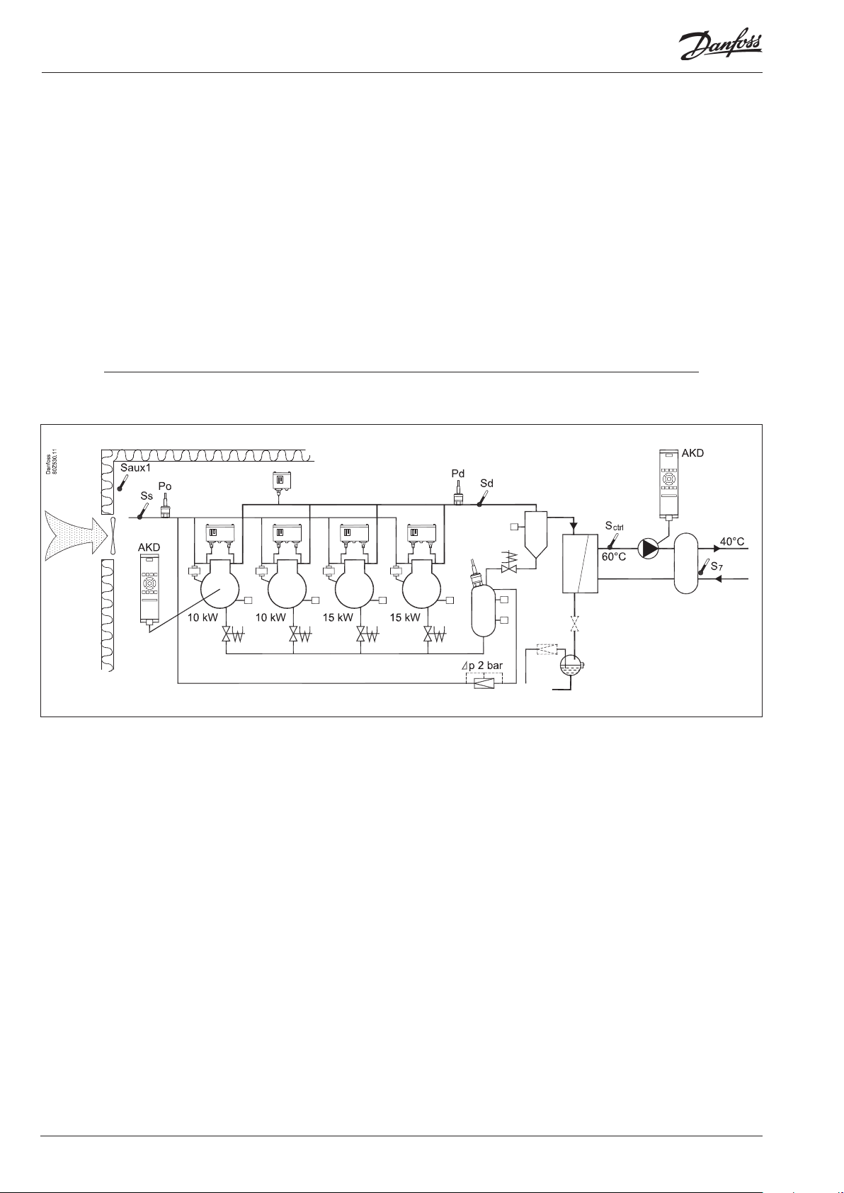
Example
Compressor Group
• Refrigerant CO2 (R744)
• 4 only compressors with "Best t". Speed control of one.
• Safety monitoring of each compressor
• Common high-pressure monitoring
• Sctrl setting 60°C, Night setback of 5 K
• Oil management of each compressor
• Pulse reset for stopped compressor (lack of oil)
Receiver
• Pump with speed control
• S7 reference 40°C
Oil Receiver:
• Monitoring of liquid level
• Control of pressure in oil receiver
Fan in plant room
• Thermostat control of fan in engine room
Safety functions:
• Monitoring of P0, Pd, Sd and superheat in suction line
• P0 max = 10°C, P0 min = -2°C
• Pd max = 50 °C
• Sd max = 120°C
• SH min = 5 °C, SH max = 35 °C
• Monitoring of low and high level in oil receiver
Other:
• Alarm output used
• External main switch used
Data from this example is used on the next page.
The result is that the following modules should be used:
• AK-HP 780 controller
• AK-XM 102B digital input module
• AK-XM 205B input and output module
• AK-OB 110 analog extension module
30 Heat pump controller RS8GF202 © Danfoss 2015-08 AK-HP 780
 Loading...