

Page 1

ADAP-KOOL® Drive Programming Guide Contents
Contents
1 Introduction
Symbols 3
Abbreviations 4
Definitions 4
Electrical wiring - control cables 10
2 How to Programme
Local Control Panel 15
How to operate graphical LCP (GLCP) 15
3 Parameter Description
Parameter Selection 31
Main Menu Structure 31
Main Menu - Operation and Display - Group 0 31
Main Menu - Load and Motor - Group 1 46
Main Menu - Brakes - Group 2 56
Main Menu - Reference/Ramps - Group 3 57
Main Menu - Limits/Warnings - Group 4 64
3
15
31
Main Menu - Digital In/Out - Group 5 68
Main Menu - Analog In/Out - Group 6 85
Main Menu - Communications and Options - Group 8 95
Main Menu - Smart Logic - Group 13 103
Main Menu - Special Functions -Group 14 118
Main Menu - Frequency Converter Information - Group 15 126
Main Menu - Data Readouts - Group 16 134
Main Menu - Data Readouts 2 - Group 18 142
Main Menu - FC Closed Loop - Group 20 145
Main Menu - Extended Closed Loop - Group 21 157
Main Menu - Application Functions - Group 22 170
22-78 Minimum Run Time Override 180
22-79 Minimum Run Time Override Value 180
Main Menu - Time-based Functions - Group 23 185
Main Menu - Pack Controller - Group 25 200
Main Menu - Analog I/O Option MCB 109 - Group 26 209
Compressor Functions - group 28 218
4 Parameter Lists
Parameter Options 223
Default settings 223
0-** Operation and Display 224
1-** Load / Motor 226
MG.11.N1.02 - VLT® is a registered Danfoss trademark
223
1
Page 2

Contents ADAP-KOOL® Drive Programming Guide
2-** Brakes 227
3-** Reference / Ramps 228
4-** Limits / Warnings 229
5-** Digital In / Out 230
6-** Analog In / Out 232
8-** Communication and Options 234
11-** ADAP-KOOL LON 235
13-** Smart Logic Controller 236
14-** Special Functions 237
15-** FC Information 238
16-** Data Readouts 240
18-** Info & Readouts 242
20-** FC Closed Loop 243
21-** Ext. Closed Loop 244
22-** Application Functions 246
23-** Time Based Funtions 248
25-** Pack Controller 249
26-** Analog I / O Option MCB 109 251
28-** Compressor Functions 252
5 Troubleshooting
Alarms and warnings 253
Alarm words 256
Warning words 257
Extended status words 258
Fault messages 259
253
2
MG.11.N1.02 - VLT® is a registered Danfoss trademark
Page 3
ADAP-KOOL® Drive Programming Guide 1 Introduction
1Introduction
1
1.1.1
Software Version and Approvals: ADAP-KOOL
ADAP-KOOL® Drive
Operating Instructions
Software version: 2.xx
This Operating Instructions can be used for all ADAP-KOOL® Drive frequency converters with software version 2.xx.
The software version number can be seen from parameter 15-43.
®
Drive
1.1.2 Symbols
Symbols used in this guide.
NB!
Indicates something to be noted by the reader.
Indicates a general warning.
Indicates a high-voltage warning.
* Indicates default setting
MG.11.N1.02 - VLT® is a registered Danfoss trademark
3
Page 4
1 Introduction ADAP-KOOL® Drive Programming Guide
1.1.3 Abbreviations
1
Alternating current AC
American wire gauge AWG
Ampere/AMP A
Automatic Motor Adaptation AMA
Current limit I
LIM
Degrees Celsius °C
Direct current DC
Drive Dependent D-TYPE
Electro Magnetic Compatibility EMC
Electronic Thermal Relay ETR
Drive FC
Gram g
Hertz Hz
Kilohertz kHz
Local Control Panel LCP
Meter m
Millihenry Inductance mH
Milliampere mA
Millisecond ms
Minute min
Motion Control Tool MCT
Nanofarad nF
Newton Meters Nm
Nominal motor current I
Nominal motor frequency f
Nominal motor power P
Nominal motor voltage U
M,N
M,N
M,N
M,N
Parameter par.
Protective Extra Low Voltage PELV
Printed Circuit Board PCB
Rated Inverter Output Current I
INV
Revolutions Per Minute RPM
Regenerative terminals Regen
Second s
Synchronous Motor Speed n
Torque limit T
s
LIM
Volts V
The maximum output current I
The rated output current supplied by the frequency converter I
VLT,MAX
VLT,N
1.1.4 Definitions
Frequency converter:
D-TYPE
Size and type of the connected frequency converter (dependencies).
I
VLT,MAX
The maximum output current.
I
VLT,N
The rated output current supplied by the frequency converter.
U
VLT, MAX
The maximum output voltage.
Input:
Control command
You can start and stop the connected motor by means of LCP and the
digital inputs.
Functions are divided into two groups.
Functions in group 1 have higher priority than functions in group 2.
Motor:
f
JOG
The motor frequency when the jog function is activated (via digital terminals).
f
M
The motor frequency.
Group 1
Reset, Coasting stop, Reset and Coasting
stop, Quick-stop, DC braking, Stop and the
"Off" key.
Group 2 Start, Pulse start, Reversing, Start reversing,
Jog and Freeze output
4
MG.11.N1.02 - VLT® is a registered Danfoss trademark
Page 5
ADAP-KOOL® Drive Programming Guide 1 Introduction
f
MAX
The maximum motor frequency.
f
MIN
The minimum motor frequency.
f
M,N
The rated motor frequency (nameplate data).
I
M
The motor current.
I
M,N
The rated motor current (nameplate data).
M-TYPE
Size and type of the connected motor (dependencies).
n
M,N
The rated motor speed (nameplate data).
n
s
Synchronous motor speed
2×
par
n
=
s
P
M,N
. 1 − 23 × 60
par
. 1 − 39
s
The rated motor power (nameplate data).
1
T
M,N
The rated torque (motor).
U
M
The instantaneous motor voltage.
U
M,N
The rated motor voltage (nameplate data).
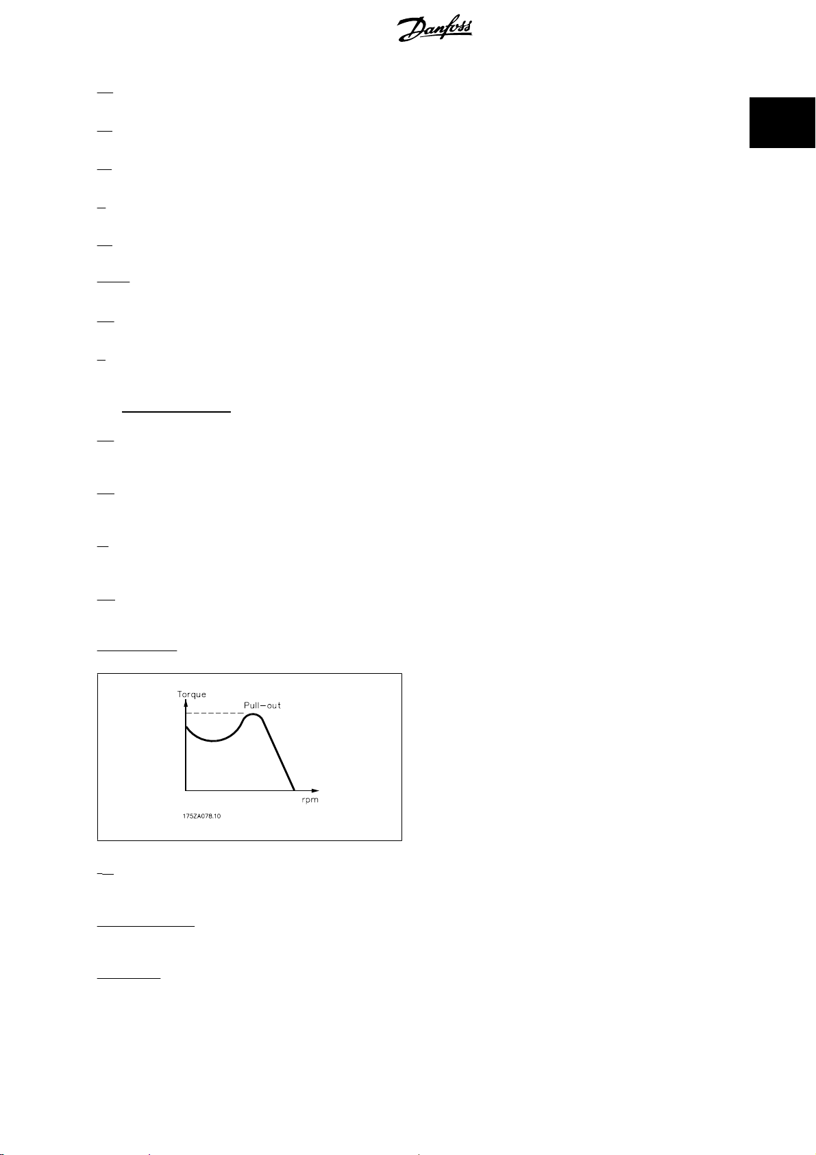
Break-away torque
η
VLT
The efficiency of the frequency converter is defined as the ratio between the power output and the power input.
Start-disable command
A stop command belonging to the group 1 control commands - see this group.
Stop command
See Control commands.
MG.11.N1.02 - VLT® is a registered Danfoss trademark
5
Page 6

1
1 Introduction ADAP-KOOL® Drive Programming Guide
References:
Analog Reference
A signal transmitted to the analog inputs 53 or 54, can be voltage or current.
Binary Reference
A signal transmitted to the serial communication port.
Preset Reference
A defined preset reference to be set from -100% to +100% of the reference range. Selection of eight preset references via the digital terminals.
Pulse Reference
A pulse frequency signal transmitted to the digital inputs (terminal 29 or 33).
Ref
MAX
Determines the relationship between the reference input at 100% full scale value (typically 10 V, 20mA) and the resulting reference. The maximum
reference value set in par. 3-03
Ref
MIN
Determines the relationship between the reference input at 0% value (typically 0V, 0mA, 4mA) and the resulting reference. The minimum reference value
set in par. 3-02
Miscellaneous:
Analog Inputs
The analog inputs are used for controlling various functions of the frequency converter.
There are two types of analog inputs:
Current input, 0-20 mA and 4-20 mA
Voltage input, 0-10 V DC ()
Voltage input, -10 - +10 V DC ().
Analog Outputs
The analog outputs can supply a signal of 0-20 mA, 4-20 mA.
Automatic Motor Adaptation, AMA
AMA algorithm determines the electrical parameters for the connected motor at standstill.
Brake Resistor
The brake resistor is a module capable of absorbing the brake power generated in regenerative braking. This regenerative braking power increases the
intermediate circuit voltage and a brake chopper ensures that the power is transmitted to the brake resistor.
CT Characteristics
Constant torque characteristics used for all applications such as conveyor belts, displacement pumps and cranes.
Digital Inputs
The digital inputs can be used for controlling various functions of the frequency converter.
Digital Outputs
The frequency converter features two Solid State outputs that can supply a 24 V DC (max. 40 mA) signal.
DSP
Digital Signal Processor.
ETR
Electronic Thermal Relay is a thermal load calculation based on present load and time. Its purpose is to estimate the motor temperature.
Hiperface
Hiperface® is a registered trademark by Stegmann.
Initialising
If initialising is carried out (par. 14-22
Intermittent Duty Cycle
An intermittent duty rating refers to a sequence of duty cycles. Each cycle consists of an on-load and an off-load period. The operation can be either
periodic duty or non-periodic duty.
LCP
The Local Control Panel (LCP) makes up a complete interface for control and programming of the frequency converter. The control panel is detachable
and can be installed up to 3 metres from the frequency converter, i.e. in a front panel by means of the installation kit option.
lsb
Least significant bit.
Minimum Reference
®
Maximum Reference
.
Operation Mode
.
), the frequency converter returns to the default setting.
6
MG.11.N1.02 - VLT® is a registered Danfoss trademark
Page 7

ADAP-KOOL® Drive Programming Guide 1 Introduction
msb
Most significant bit.
MCM
2
Short for Mille Circular Mil, an American measuring unit for cable cross-section. 1 MCM = 0.5067 mm
On-line/Off-line Parameters
Changes to on-line parameters are activated immediately after the data value is changed. Changes to off-line parameters are not activated until you enter
[OK] on the LCP.
Process PID
The PID regulator maintains the desired speed, pressure, temperature, etc. by adjusting the output frequency to match the varying load.
PCD
Process Data
Pulse Input/Incremental Encoder
An external, digital pulse transmitter used for feeding back information on motor speed. The encoder is used in applications where great accuracy in
speed control is required.
RCD
Residual Current Device.
Set-up
You can save parameter settings in four Set-ups. Change between the four parameter Set-ups and edit one Set-up, while another Set-up is active.
SFAVM
Switching pattern called
Slip Compensation
The frequency converter compensates for the motor slip by giving the frequency a supplement that follows the measured motor load keeping the motor
speed almost constant..
Smart Logic Control (SLC)
The SLC is a sequence of user defined actions executed when the associated user defined events are evaluated as true by the Smart Logic Controller.
(Parameter group 13-xx
The SLC is a sequence of user defined actions executed when the associated user defined events are evaluated as true by the Smart Logic Controller.
(Parameter group 13-xx).
STW
Status Word
FC Standard Bus
Includes RS 485 bus with FC protocol or MC protocol. See par. 8-30
Thermistor:
A temperature-dependent resistor placed where the temperature is to be monitored (frequency converter or motor).
Trip
A state entered in fault situations, e.g. if the frequency converter is subject to an over-temperature or when the frequency converter is protecting the
motor, process or mechanism. Restart is prevented until the cause of the fault has disappeared and the trip state is cancelled by activating reset or, in
some cases, by being programmed to reset automatically. Trip may not be used for personal safety.
Trip Locked
A state entered in fault situations when the frequency converter is protecting itself and requiring physical intervention, e.g. if the frequency converter is
subject to a short circuit on the output. A locked trip can only be cancelled by cutting off mains, removing the cause of the fault, and reconnecting the
frequency converter. Restart is prevented until the trip state is cancelled by activating reset or, in some cases, by being programmed to reset automatically.
Trip may not be used for personal safety.
VT Characteristics
Variable torque characteristics used for pumps and fans.
plus
VVC
If compared with standard voltage/frequency ratio control, Voltage Vector Control (VVC
reference is changed and in relation to the load torque.
Stator Flux oriented Asynchronous Vector Modulation (par. 14-00
Smart Logic Control (SLC)
Protocol
.
plus
Switching Pattern
) improves the dynamics and the stability, both when the speed
.
).
1
60° AVM
Switching pattern called 60°
Asynchronous Vector Modulation (par. 14-00
MG.11.N1.02 - VLT® is a registered Danfoss trademark
Switching Pattern
).
7
Page 8
1 Introduction ADAP-KOOL® Drive Programming Guide
1
Power Factor
The power factor is the relation between I
The power factor for 3-phase control:
The power factor indicates to which extent the frequency converter im-
poses a load on the mains supply.
The lower the power factor, the higher the I
formance.
In addition, a high power factor indicates that the different harmonic currents are low.
The frequency converters' built-in DC coils produce a high power factor, which minimizes the imposed load on the mains supply.
and I
1
.
RMS
for the same kW per-
RMS
Power factor
I1 x cos
=
I
RMS
I
=
RMS
I
ϕ1
2
1
=
=
+
3 x U x
3 x U x
I
RMS
2
I
+
5
I
1
2
I
7
I
cos
1
I
RMS
since cos
+ .. +
ϕ
ϕ1 = 1
2
I
n
1.1.5 Safety Precautions
The voltage of the frequency converter is dangerous whenever connected to mains. Incorrect installation of the motor, frequency
converter or fieldbus may cause damage to the equipment, serious personal injury or death. Consequently, the instructions in this
manual, as well as national and local rules and safety regulations, must be complied with.
Safety Regulations
1. The mains supply to the frequency converter must be disconnected whenever repair work is to be carried out. Check that the mains supply has
been disconnected and that the necessary time has elapsed before removing motor and mains supply plugs.
2. The [OFF] button on the control panel of the frequency converterr does not disconnect the mains supply and consequently it must not be used
as a safety switch.
3. The equipment must be properly earthed, the user must be protected against supply voltage and the motor must be protected against overload
in accordance with applicable national and local regulations.
4. The earth leakage current exceeds 3.5 mA.
5. Protection against motor overload is not included in the factory setting. If this function is desired, set par. 1-90
data value ETR trip 1 [4] or data value ETR warning 1 [3].
6. Do not remove the plugs for the motor and mains supply while the frequency converter is connected to mains. Check that the mains supply has
been disconnected and that the necessary time has elapsed before removing motor and mains plugs.
7. Please note that the frequency converter has more voltage sources than L1, L2 and L3, when load sharing (linking of DC intermediate circuit)
or external 24 V DC are installed. Check that all voltage sources have been disconnected and that the necessary time has elapsed before
commencing repair work.
Warning against unintended start
1. The motor can be brought to a stop by means of digital commands, bus commands, references or a local stop, while the frequency converter
is connected to mains. If personal safety considerations (e.g. risk of personal injury caused by contact with moving machine parts following an
unintentional start) make it necessary to ensure that no unintended start occurs, these stop functions are not sufficient. In such cases the mains
supply must be disconnected or the
2. The motor may start while setting the parameters. If this means that personal safety may be compromised (e.g. personal injury caused by
contact with moving machine parts), motor starting must be prevented, for instance by use of the
of the motor connection.
3. A motor that has been stopped with the mains supply connected, may start if faults occur in the electronics of the frequency converter, through
temporary overload or if a fault in the power supply grid or motor connection is remedied. If unintended start must be prevented for personal
safety reasons (e.g. risk of injury caused by contact with moving machine parts), the normal stop functions of the frequency converter are not
sufficient. In such cases the mains supply must be disconnected or the
Safe Stop
function must be activated.
Safe Stop
function must be activated.
Safe Stop
Motor Thermal Protection
function or secure disconnection
to
NB!
Safe Stop
When using the
8
function, always follow the instructions in the
MG.11.N1.02 - VLT® is a registered Danfoss trademark
Safe Stop
section of the Design Guide.
Page 9
ADAP-KOOL® Drive Programming Guide 1 Introduction
4. Control signals from, or internally within, the frequency converter may in rare cases be activated in error, be delayed or fail to occur entirely.
When used in situations where safety is critical, e.g. when controlling the electromagnetic brake function of a hoist application, these control
signals must not be relied on exclusively.
Touching the electrical parts may be fatal - even after the equipment has been disconnected from mains.
Also make sure that other voltage inputs have been disconnected, such as external 24 V DC, load sharing (linkage of DC intermediate circuit), as well as
the motor connection for kinetic back up.
Systems where frequency converters are installed must, if necessary, be equipped with additional monitoring and protective devices according to the
valid safety regulations, e.g law on mechanical tools, regulations for the prevention of accidents etc. Modifications on the frequency converters by means
of the operating software are allowed.
Hoisting applications:
The frequency converter functions for controlling mechanical brakes cannot be considered as a primary safety circuit. There must always be a redundancy
for controlling external brakes.
Protection Mode
Once a hardware limit on motor current or dc-link voltage is exceeded the drive will enter “Protection mode”. “Protection mode” means a change of the
PWM modulation strategy and a low switching frequency to minimize losses. This continues 10 sec after the last fault and increases the reliability and
the robustness of the drive while re-establishing full control of the motor.
In hoist applications “Protection mode” is not usable because the drive will usually not be able to leave this mode again and therefore it will extend the
time before activating the brake – which is not recommendable.
The “Protection mode” can be disabled by setting par. 14-26
of the hardware limits is exceeded.
Trip Delay at Inverter Fault
to zero which means that the drive will trip immediately if one
1
NB!
It is recommended to disable protection mode in hoisting applications (par. 14-26
Trip Delay at Inverter Fault
= 0)
MG.11.N1.02 - VLT® is a registered Danfoss trademark
9
Page 10
1
1 Introduction ADAP-KOOL® Drive Programming Guide
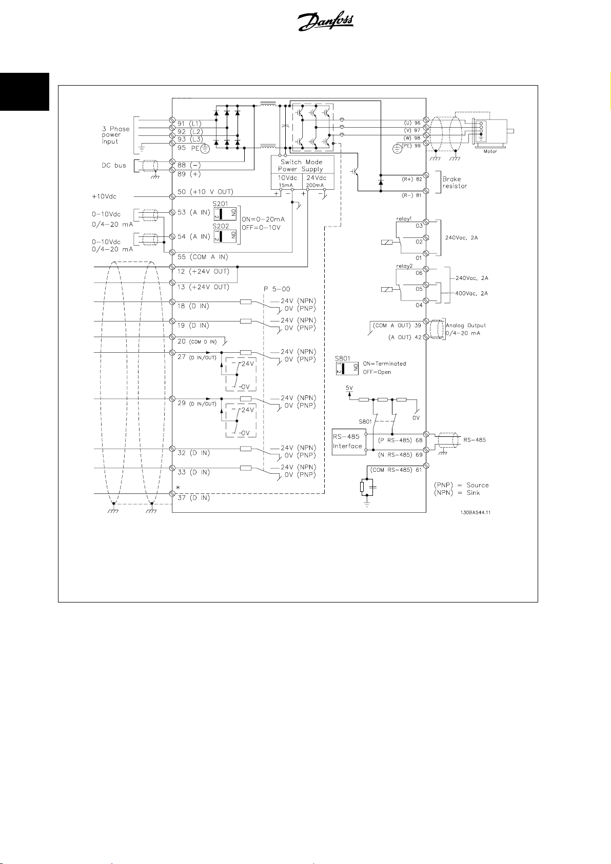
1.1.6 Electrical wiring - control cables
Illustration 1.1: Diagram showing all electrical terminals without options.
Terminal 37 is the input to be used for Safe Stop. For instructions on Safe Stop installation please refer to the section
of the Design Guide.
tion
* Terminal 37 is not included in (Except A1, which includes Safe Stop).
Terminal 29 and Relay 2, are not included in .
Very long control cables and analogue signals may in rare cases and depending on installation result in 50/60 Hz earth loops due to noise from mains
supply cables.
If this occurs, it may be necessary to break the screen or insert a 100 nF capacitor between screen and chassis.
The digital and analogue inputs and outputs must be connected separately to the common inputs (terminal 20, 55, 39) of the frequency converter to
avoid ground currents from both groups to affect other groups. For example, switching on the digital input may disturb the analog input signal.
Safe Stop Installa-
10
MG.11.N1.02 - VLT® is a registered Danfoss trademark
Page 11
ADAP-KOOL® Drive Programming Guide 1 Introduction
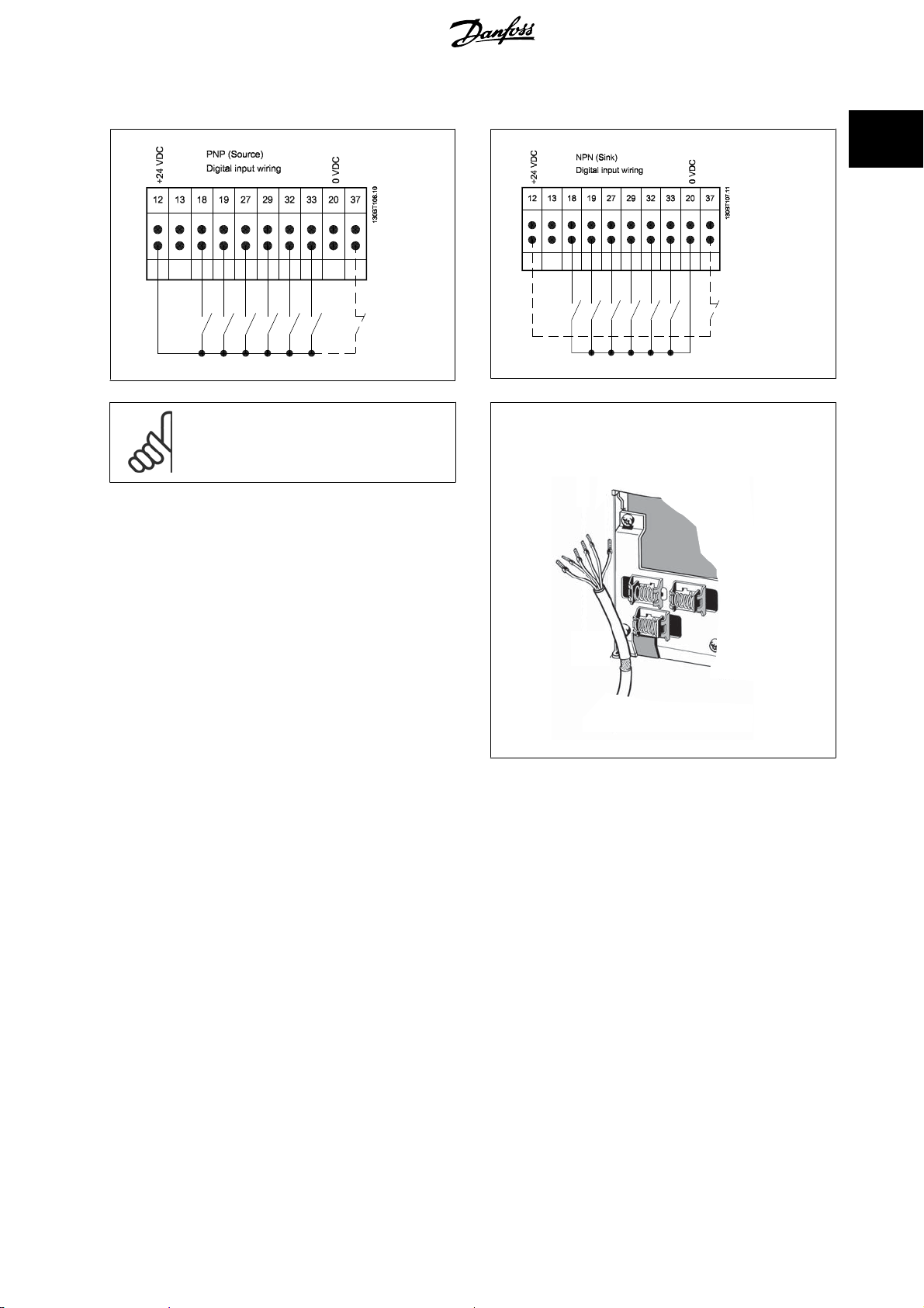
Input polarity of control terminals
1
NB!
Control cables must be screened/armoured.
See section entitled
the correct termination of control cables.
Earthing of Screened/Armoured Control Cables
130BA681.10
for
130BA681.10
MG.11.N1.02 - VLT® is a registered Danfoss trademark
11
Page 12
1 Introduction ADAP-KOOL® Drive Programming Guide
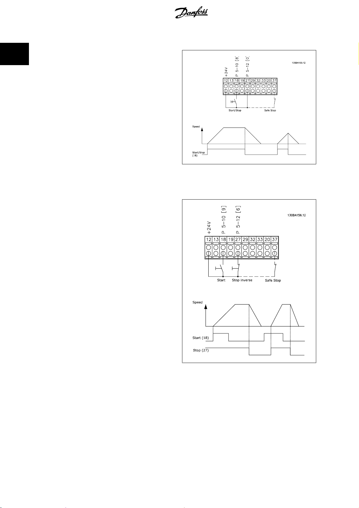
1.1.7 Start/Stop
1
Terminal 18 = par. 5-10
Terminal 27 = par. 5-12
fault
coast inverse
Terminal 37 = Safe stop (where available!)
Terminal 18 Digital Input
Terminal 27 Digital Input
)
1.1.8 Pulse Start/Stop
Terminal 18 = par. 5-10
Terminal 27= par. 5-12
Terminal 37 = Safe stop (where available!)
Terminal 18 Digital Input
Terminal 27 Digital Input
[8]
Start
[0]
No operation
Latched start, [9]
Stop inverse, [6]
(De-
12
MG.11.N1.02 - VLT® is a registered Danfoss trademark
Page 13
ADAP-KOOL® Drive Programming Guide 1 Introduction
1.1.9 Speed Up/Down
Terminals 29/32 = Speed up/down:.
Terminal 18 = par. 5-10
fault)
Terminal 27 = par. 5-12
ence [19]
Terminal 29 = par. 5-13
Terminal 32 = par. 5-14
[22]
Note: Terminal 29 only in FC x02 (x=series type).
Terminal 18 Digital Input
Terminal 27 Digital Input
Terminal 29 Digital Input
Terminal 32 Digital Input
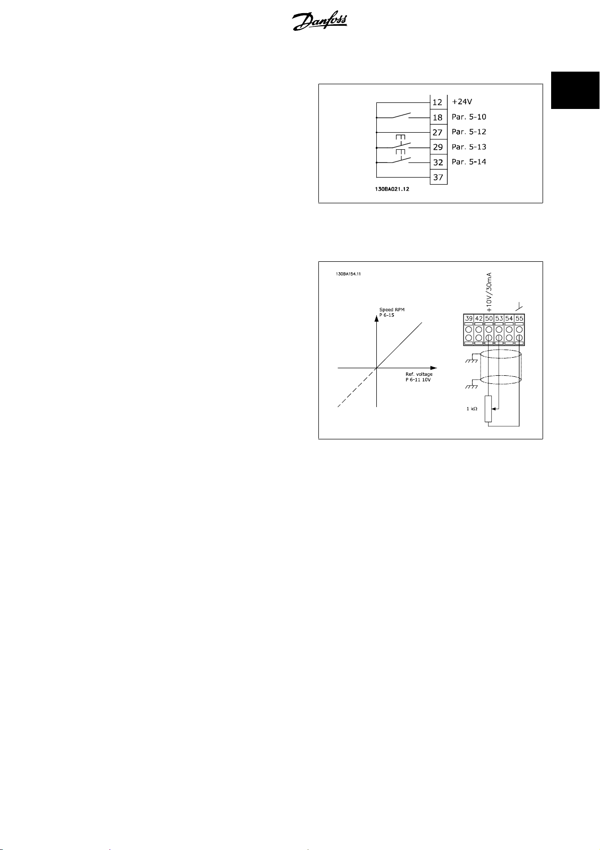
1.1.10 Potentiometer Reference
Voltage reference via a potentiometer:
Reference Source 1 = [1]
Terminal 53, Low Voltage = 0 Volt
Terminal 53, High Voltage = 10 Volt
Terminal 53, Low Ref./Feedback = 0 RPM
Terminal 53, High Ref./Feedback = 1500 RPM
Switch S201 = OFF (U)
Analog input 53
(default)
Start [9] (de-
Freeze refer-
Speed up [21]
Speed down
1
MG.11.N1.02 - VLT® is a registered Danfoss trademark
13
Page 14

2
2 How to Programme ADAP-KOOL® Drive Programming Guide
14
MG.11.N1.02 - VLT® is a registered Danfoss trademark
Page 15
ADAP-KOOL® Drive Programming Guide 2 How to Programme
2 How to Programme
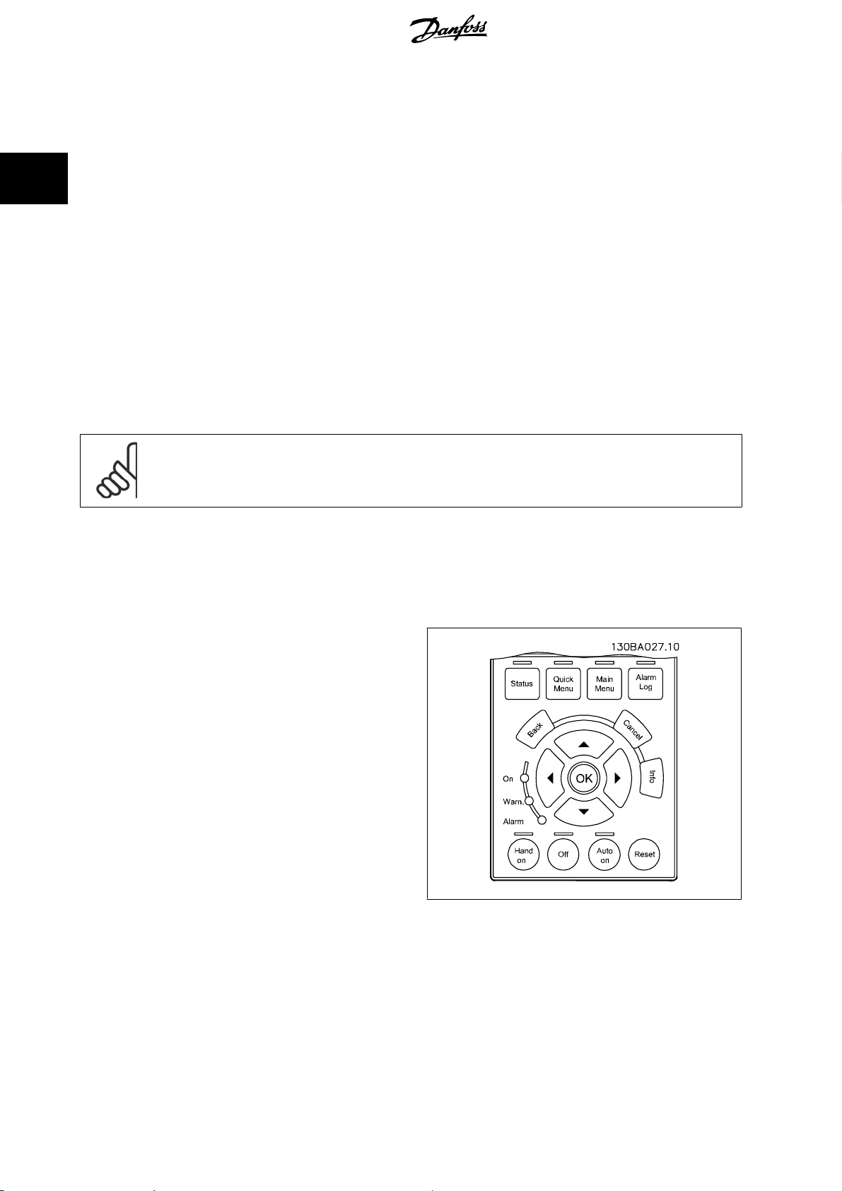
2.1 Local Control Panel
2.1.1 How to operate graphical LCP (GLCP)
The following instructions are valid for the GLCP (LCP 102).
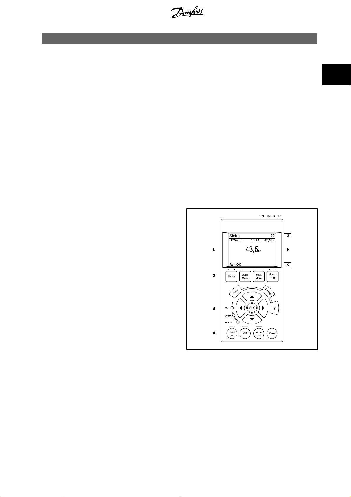
The GLCP is divided into four functional groups:
1. Graphical display with Status lines.
2. Menu keys and indicator lights (LED's) - selecting mode, changing parameters and switching between display functions.
3. Navigation keys and indicator lights (LEDs).
4. Operation keys and indicator lights (LEDs).
Graphical display:
The LCD-display is back-lit with a total of 6 alpha-numeric lines. All data is displayed on the LCP which can show up to five operating variables while in
[Status] mode.
Display lines:
a. Status line: Status messages displaying icons and graphics.
b. Line 1-2: Operator data lines displaying data and variables de-
fined or chosen by the user. By pressing the [Status] key, up to
one extra line can be added.
c. Status line: Status messages displaying text.
2
MG.11.N1.02 - VLT® is a registered Danfoss trademark
15
Page 16
2 How to Programme ADAP-KOOL® Drive Programming Guide
The display is divided into 3 sections:
Top section (a) shows the status when in status mode or up to 2 variables when not in status mode and in the case of Alarm/Warning.
2
The number of the Active Set-up (selected as the Active Set-up in par.0-10
Set-up, the number of the Set-up being programmed appears to the right in brackets.
The Middle section (b) shows up to 5 variables with related unit, regardless of status. In case of alarm/warning, the warning is shown instead of the
variables.
It is possible to toggle between three status read-out displays by pressing the [Status] key.
Operating variables with different formatting are shown in each status screen - see below.
Several values or measurements can be linked to each of the displayed operating variables. The values / measurements to be displayed can be defined
via par.0-20
Line 3 Large
Each value / measurement readout parameter selected in par.0-20
of digits after a possible decimal point. Larger numeric values are displayed with few digits after the decimal point.
Ex.: Current readout
5.25 A; 15.2 A 105 A.
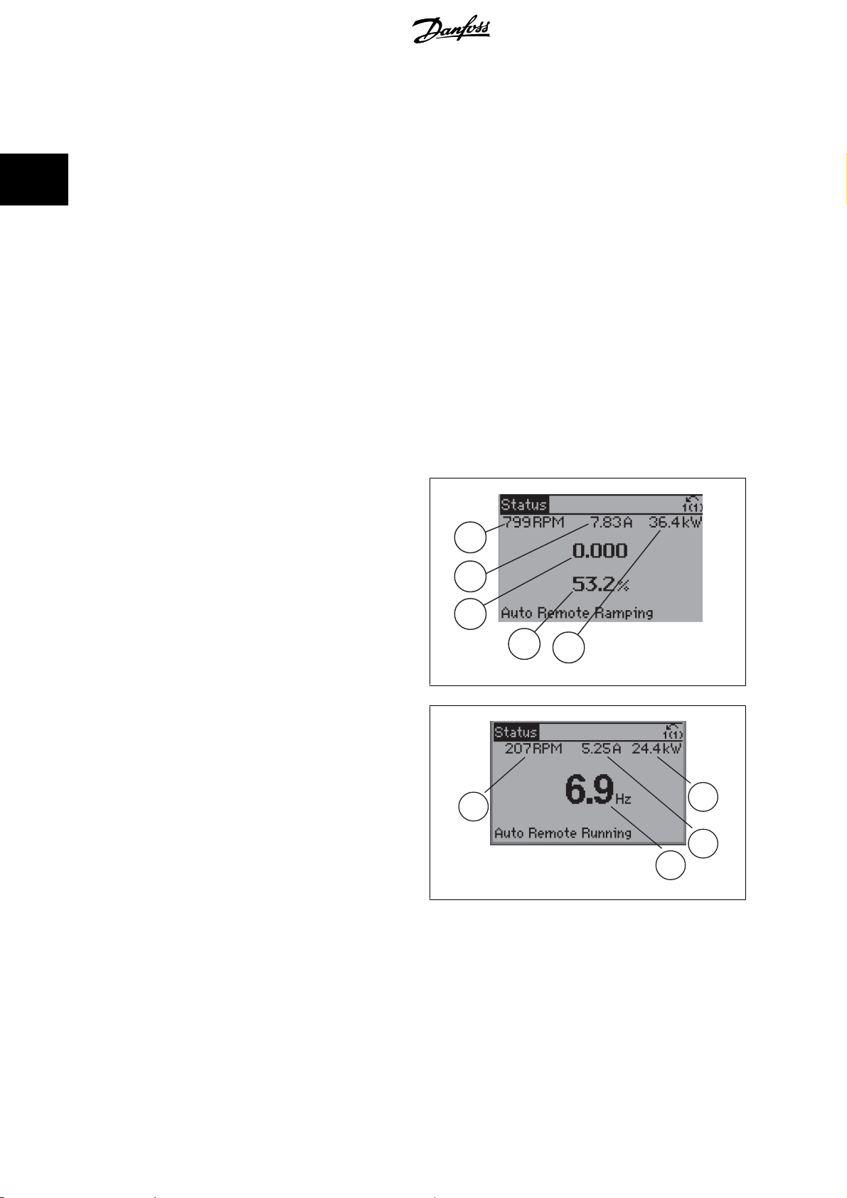
Status display I:
This read-out state is standard after start-up or initialization.
Use [INFO] to obtain information about the value/measurement linked to
the displayed operating variables (1.1, 1.2, 1.3, 2, and 3).
See the operating variables shown in the display in this illustration. 1.1,
1.2 and 1.3 are shown in small size. 2 and 3 are shown in medium size.
Display Line 1.1 Small
, which can be accessed via [QUICK MENU], "Q3 Function Setups", "Q3-1 General Settings", "Q3-13 Display Settings".
, par. 0-21
Display Line 1.2 Small
Active Set-up
, par. 0-22
Display Line 1.1 Small
Display Line 1.3 Small
) is shown. When programming in another Set-up than the Active
, par. 0-23
to par. 0-24
1.1
1.2
Display Line 2 Large
Display Line 3 Large
and par. 0-24
has its own scale and number
Display
130BP041.10
Status display II:
See the operating variables (1.1, 1.2, 1.3, and 2) shown in the display in
this illustration.
In the example, Speed, Motor current, Motor power and Frequency are
selected as variables in the first and second lines.
1.1, 1.2 and 1.3 are shown in small size. 2 is shown in large size.
2
130BP062.10
1.1
3
1.3
1.3
1.2
2
16
MG.11.N1.02 - VLT® is a registered Danfoss trademark
Page 17
30BP063.10
ADAP-KOOL® Drive Programming Guide 2 How to Programme
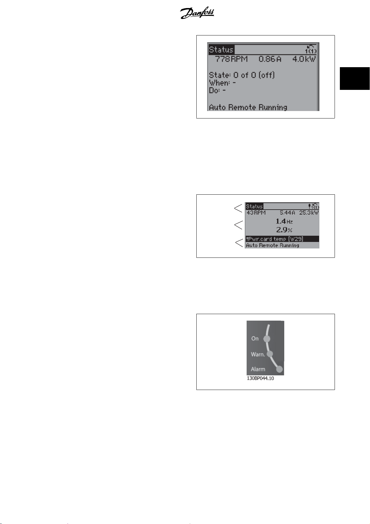
Status display III:
This state displays the event and action of the Smart Logic Control. For
further information, see section
The Bottom section always shows the state of the frequency converter
in Status mode.
Display Contrast Adjustment
Smart Logic Control
.
1
2
Press [status] and [
Press [status] and [
Indicator lights (LEDs):
If certain threshold values are exceeded, the alarm and/or warning LED lights up. A status and alarm text appear on the control panel.
The On LED is activated when the frequency converter receives power from mains voltage, a DC bus terminal, or an external 24 V supply. At the same
time, the back light is on.
• Green LED/On: Control section is working.
• Yellow LED/Warn.: Indicates a warning.
• Flashing Red LED/Alarm: Indicates an alarm.
] for darker display
▲
] for brighter display
▼
Top section
Middle section
Bottom section
130BP074.10
MG.11.N1.02 - VLT® is a registered Danfoss trademark
17
Page 18

2
2 How to Programme ADAP-KOOL® Drive Programming Guide
GLCPkeys
Menu keys
The menu keys are divided into functions. The keys below the display and
indicator lamps are used for parameter set-up, including choice of display
indication during normal operation.
[Status]
indicates the status of the frequency converter and/or the motor. 3 different readouts can be chosen by pressing the [Status] key:
5 line readouts, 4 line readouts or Smart Logic Control.
Use [Status] for selecting the mode of display or for changing back to Display mode from either the Quick Menu mode, the Main Menu mode or Alarm
mode. Also use the [Status] key to toggle single or double read-out mode.
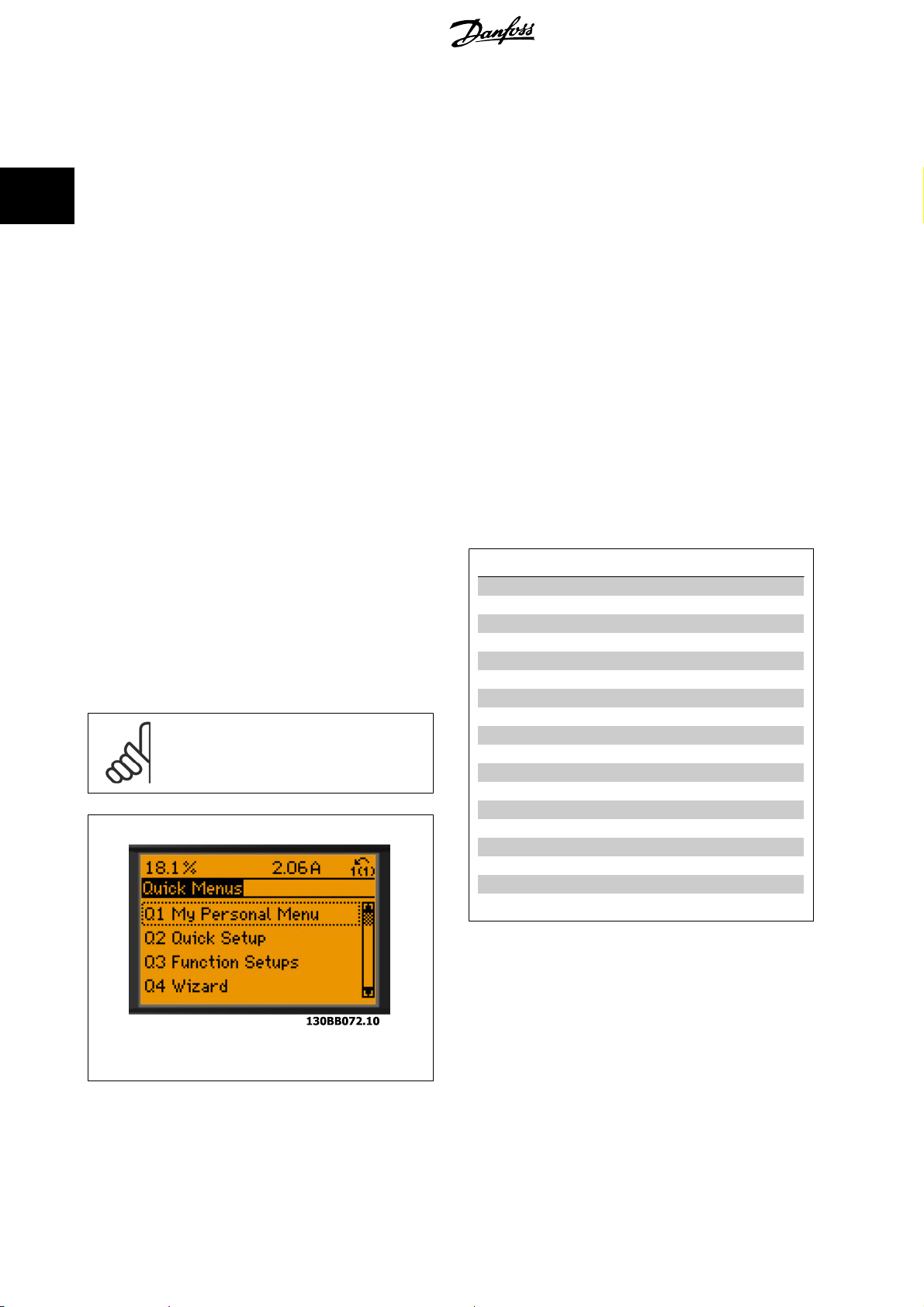
[Quick Menu]
allows quick set-up of the frequency converter. The most commonADAP-KOOL Drive AKD 102 functions can be programmed here.
The [Quick Menu] consists of:
-My Personal Menu
- Quick Set-up
- Function set-up
-Changes Made
- Loggings
The Function set-up provides quick and easy access to all parameters required for the majority of ADAP-KOOL Drive AKD 102 applications including most
VAV and CAV supply and return fans, cooling tower fans, Primary, Secondary and Condenser Water Pumps and other pump, fan and compressor appli-
cations. Amongst other features it also includes parameters for selecting which variables to display on the LCP, digital preset speeds, scaling of analog
references, closed loop single zone and multi-zone applications and specific functions related to Fans, Pumps and Compressors.
130BP045.10
The Quick Menu parameters can be accessed immediately unless a password has been created via par.0-60
Main Menu w/o Password
It is possible to switch directly between Quick Menu mode and Main Menu mode.
[Main Menu]
is used for programming all parameters.The Main Menu parameters can be accessed immediately unless a password has been created via par.0-60
Menu Password
the majority of ADAP-KOOL Drive AKD 102 applications it is not necessary to access the Main Menu parameters but instead the Quick Menu, Quick Set-
up and Function Set-up provides the simplest and quickest access to the typical required parameters.
It is possible to switch directly between Main Menu mode and Quick Menu mode.
Parameter shortcut can be carried out by pressing down the [Main Menu] key for 3 seconds. The parameter shortcut allows direct access to any
parameter.
[Alarm Log]
displays an Alarm list of the five latest alarms (numbered A1-A5). To obtain additional details about an alarm, use the arrow keys to manoeuvre to the
alarm number and press [OK]. Information is displayed about the condition of the frequency converter before it enters the alarm mode.
The Alarm log button on the LCP allows access to both Alarm log and Maintenance log.
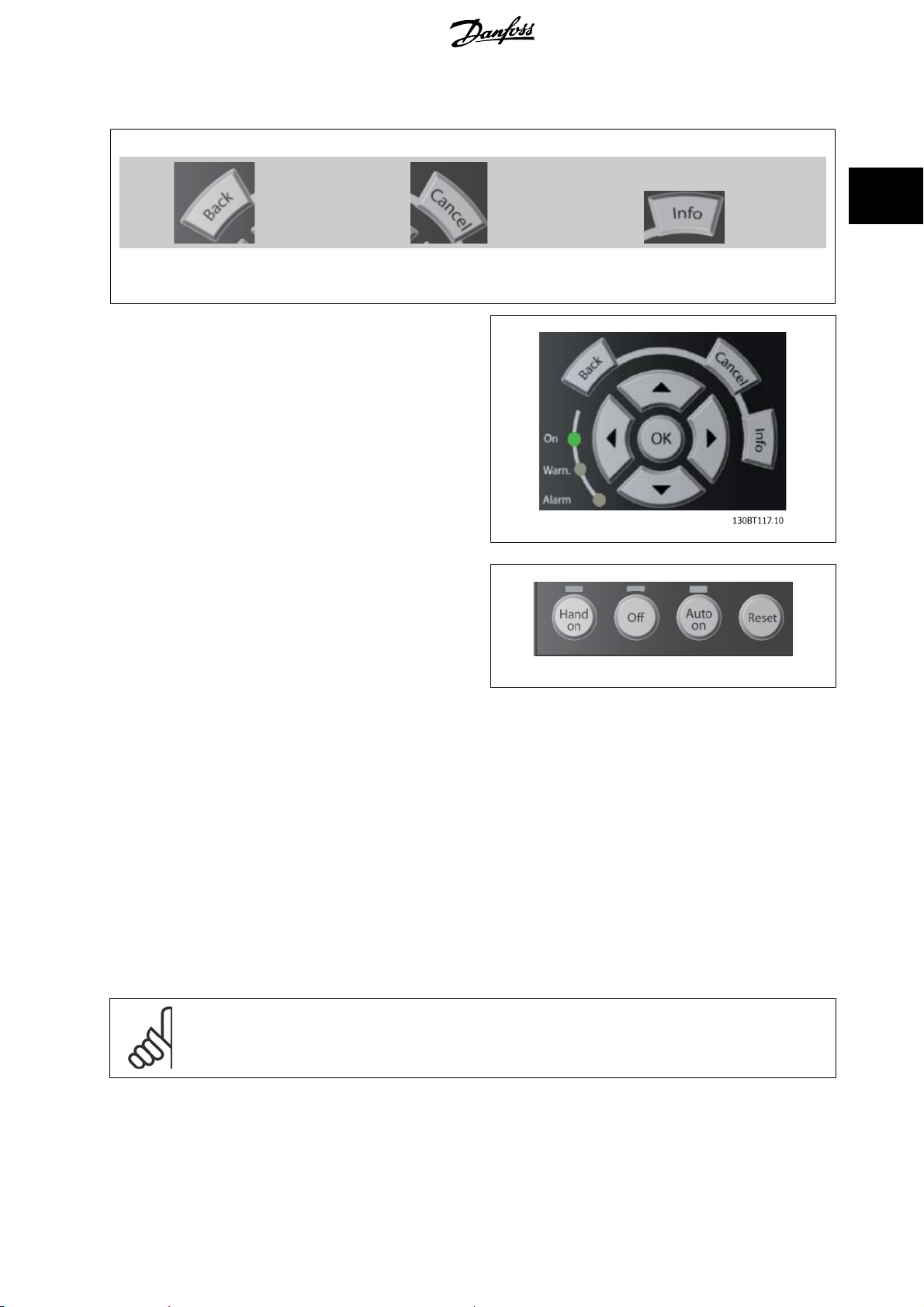
[Back]
reverts to the previous step or layer in the navigation structure.
[Cancel]
last change or command will be cancelled as long as the display has not been changed.
, par.0-61
, par.0-65
Personal Menu Password
Access to Main Menu w/o Password
or par.0-66
,par.0-65
Personal Menu Password
Access to Personal Menu w/o Password
or par.0-66
Main Menu Password
.
Access to Personal Menu w/o Password
, par.0-61
Access to
Main
. For
[Info]
displays information about a command, parameter, or function in any display window. [Info] provides detailed information when needed.
18
MG.11.N1.02 - VLT® is a registered Danfoss trademark
Page 19
ADAP-KOOL® Drive Programming Guide 2 How to Programme
Exit Info mode by pressing either [Info], [Back], or [Cancel].
2
Navigation Keys
The four navigation arrows are used to navigate between the different
choices available in [Quick Menu], [Main Menu] and [Alarm Log].
Use the keys to move the cursor.
[OK] is used for choosing a parameter marked by the cursor and for
enabling the change of a parameter.
Operation Keys for local control are found at the bottom of the control
panel.
130BP046.10
[Hand On]
enables control of the frequency converter via the GLCP. [Hand On] also starts the motor, and it is now possible to enter the motor speed data by means
of the arrow keys. The key can be selected as
The following control signals will still be active when [Hand On] is activated:
• [Hand On] - [Off] - [Auto on]
• Reset
• Coasting stop inverse
•Reversing
• Set-up select lsb - Set-up select msb
• Stop command from serial communication
•Quick stop
•DC brake
Enable
[1] or
Disable
[0] via par.0-40
[Hand on] Key on LCP
.
NB!
External stop signals activated by means of control signals or a serial bus will override a “start” command via the LCP.
[Off]
stops the connected motor. The key can be selected as Enable [1] or Disable [0] via par.0-41
and the [Off] key is inactive the motor can only be stopped by disconnecting the mains supply.
MG.11.N1.02 - VLT® is a registered Danfoss trademark
[Off] Key on LCP
. If no external stop function is selected
19
Page 20
2 How to Programme ADAP-KOOL® Drive Programming Guide
[Auto on]
enables the frequency converter to be controlled via the control terminals and/or serial communication. When a start signal is applied on the control
terminals and/or the bus, the frequency converter will start. The key can be selected as Enable [1] or Disable [0] via par.0-42
[Auto on] Key on LCP
.
2
NB!
An active HAND-OFF-AUTO signal via the digital inputs has higher priority than the control keys [Hand on] – [Auto on].
[Reset]
is used for resetting the frequency converter after an alarm (trip). It can be selected as
The parameter shortcut can be carried out by holding down the [Main Menu] key for 3 seconds. The parameter shortcut allows direct access to any
parameter.
Enable
[1] or
Disable
[0] via par.0-43
[Reset] Key on LCP
.
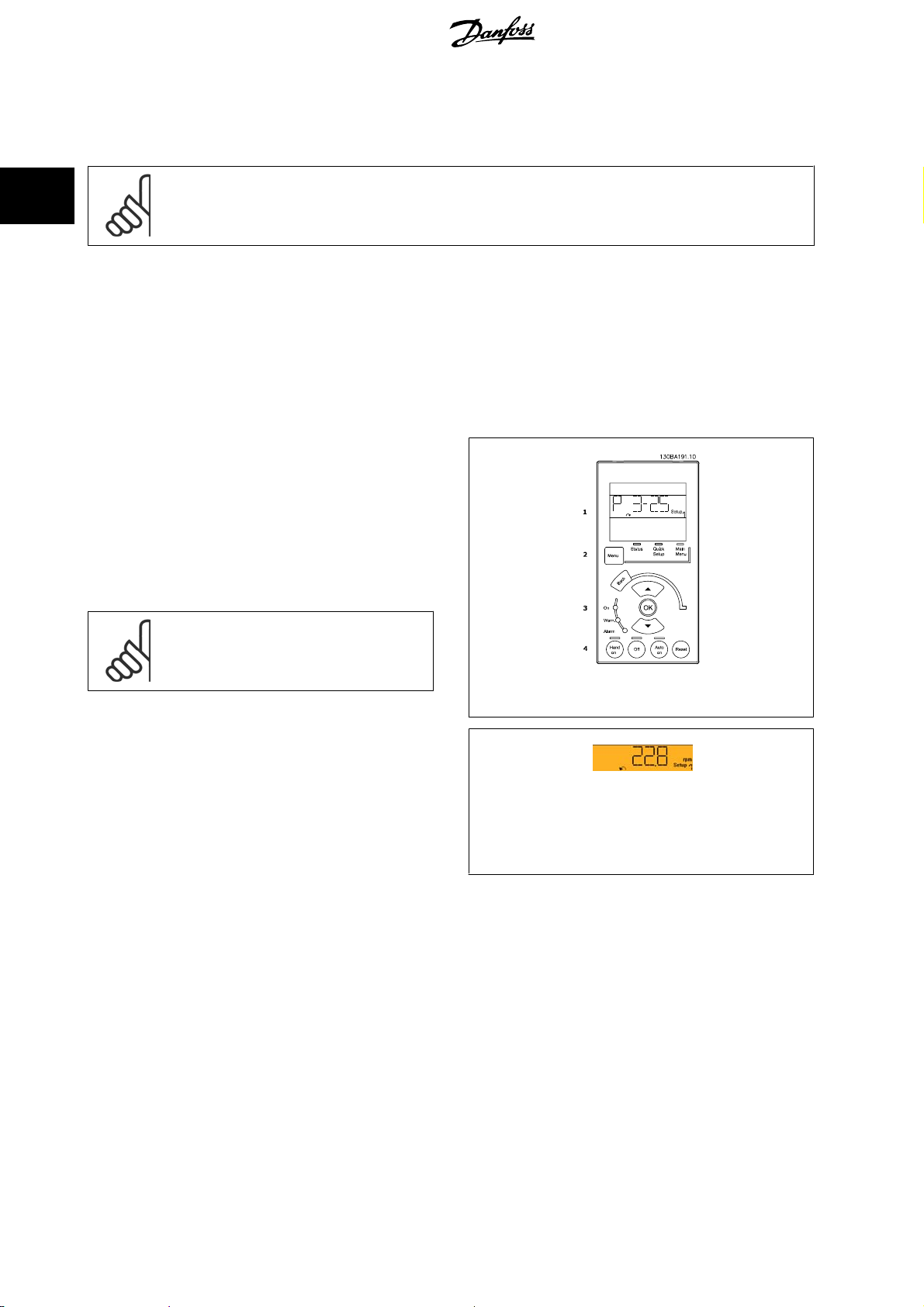
2.1.2 How to operate numeric LCP (NLCP)
The following instructions are valid for the NLCP (LCP 101).
The control panel is divided into four functional groups:
1. Numeric display.
2. Menu key and indicator lights (LEDs) - changing parameters and
switching between display functions.
3. Navigation keys and indicator lights (LEDs).
4. Operation keys and indicator lights (LEDs).
NB!
Parameter copy is not possible with Numeric Local
Control Panel (LCP101).
Illustration 2.1: Numerical LCP (NLCP)
Select one of the following modes:
Status Mode: Displays the status of the frequency converter or the mo-
tor.
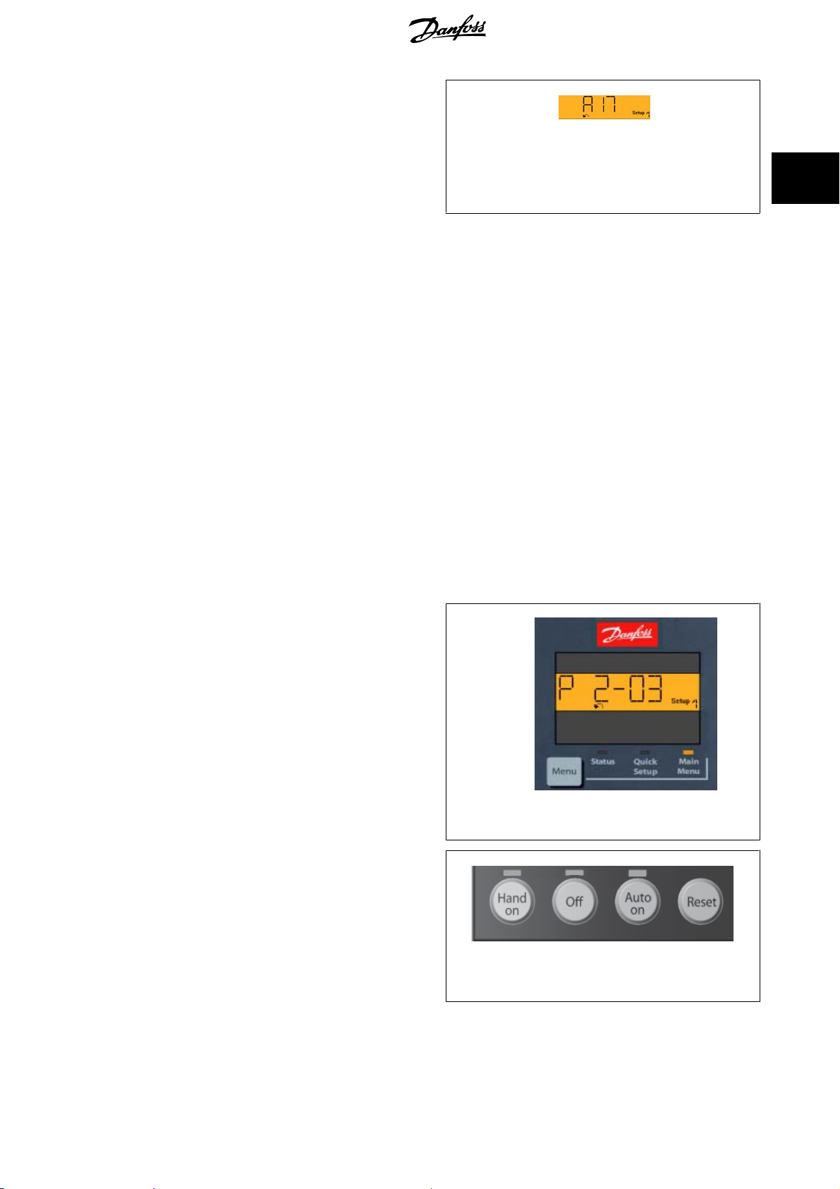
If an alarm occurs, the NLCP automatically switches to status mode.
A number of alarms can be displayed.
Quick Set-up or Main Menu Mode: Display parameters and parameter
settings.
130BP077.10
Illustration 2.2: Status display example
20
MG.11.N1.02 - VLT® is a registered Danfoss trademark
Page 21
ADAP-KOOL® Drive Programming Guide 2 How to Programme
Indicator lights (LEDs):
• Green LED/On: Indicates if control section is on.
• Yellow LED/Wrn.: Indicates a warning.
• Flashing red LED/Alarm: Indicates an alarm.
130BP078.10
Illustration 2.3: Alarm display example
Menu key
[Menu] Select one of the following modes:
• Status
•Quick Setup
• Main Menu
Main Menu is used for programming all parameters.
The parameters can be accessed immediately unless a password has been created via par.0-60
o Password
Quick Setup is used to set up the frequency converter using only the most essential parameters.
The parameter values can be changed using the up/down arrows when the value is flashing.
Select Main Menu by pressing the [Menu] key a number of times until the Main Menu LED is lit.
Select the parameter group [xx-__] and press [OK]
Select the parameter [__-xx] and press [OK]
If the parameter is an array parameter select the array number and press [OK]
Select the wanted data value and press [OK]
Navigation Keys [Back] for stepping backwards
Arrow [▼] [▲] keys are used for manoeuvring between parameter groups, parameters and within parameters.
[OK] is used for choosing a parameter marked by the cursor and for enabling the change of a parameter.
, par.0-65
Personal Menu Password
or par.0-66
Access to Personal Menu w/o Password
Main Menu Password
.
, par.0-61
2
Access to Main Menu w/
130BP079.10
Illustration 2.4: Display example
Operation Keys
Keys for local control are found at the bottom of the control panel.
130BP046.10
Illustration 2.5: Operation keys of the numerical CP (NLCP)
[Hand on]enables control of the frequency converter via the LCP. [Hand on] also starts the motor and it is now possible to enter the motor speed data
by means of the arrow keys. The key can be selected as
Enable
[1] or
Disable
[0] via par.0-40
[Hand on] Key on LCP
.
MG.11.N1.02 - VLT® is a registered Danfoss trademark
21
Page 22
2
2 How to Programme ADAP-KOOL® Drive Programming Guide
External stop signals activated by means of control signals or a serial bus will override a 'start' command via the LCP.
The following control signals will still be active when [Hand on] is activated:
• [Hand on] - [Off] - [Auto on]
• Reset
• Coasting stop inverse
• Reversing
• Set-up select lsb - Set-up select msb
• Stop command from serial communication
•Quick stop
•DC brake
Enable
[1] or
Disable
[Off] stops the connected motor. The key can be selected as
If no external stop function is selected and the [Off] key is inactive the motor can be stopped by disconnecting the mains supply.
[Auto on] enables the frequency converter to be controlled via the control terminals and/or serial communication. When a start signal is applied on the
control terminals and/or the bus, the frequency converter will start. The key can be selected as
LCP
.
[0] via par.0-41
[Off] Key on LCP
Enable
[1] or
.
Disable
[0] via par.0-42
[Auto on] Key on
NB!
An active HAND-OFF-AUTO signal via the digital inputs has higher priority than the control keys [Hand on] [Auto on].
[Reset] is used for resetting the frequency converter after an alarm (trip). It can be selected as
LCP
.
Enable
[1] or
Disable
[0] via par.0-43
2.1.3 Quick Transfer of Parameter Settings between Multiple Frequency Converters
Once the set-up of a frequency converter is complete, we recommend
that you store the data in the LCP or on a PC via MCT 10 Set-up Software
Tool.
[Reset] Key on
Data storage in LCP:
1. Go to par.0-50
2. Press the [OK] key
3. Select “All to LCP”
4. Press the [OK] key
All parameter settings are now stored in the LCP indicated by the progress bar. When 100% is reached, press [OK].
22
LCP Copy
MG.11.N1.02 - VLT® is a registered Danfoss trademark
Page 23
ADAP-KOOL® Drive Programming Guide 2 How to Programme
NB!
Stop the motor before performing this operation.
You can now connect the LCP to another frequency converter and copy the parameter settings to this frequency converter as well.
Data transfer from LCP to frequency converter:
1. Go to par.0-50
2. Press the [OK] key
3. Select “All from LCP”
4. Press the [OK] key
The parameter settings stored in the LCP are now transferred to the frequency converter indicated by the progress bar. When 100% is reached, press
[OK].
LCP Copy
NB!
Stop the motor before performing this operation.
2.1.4 Parameter Set-Up
The frequency converter can be used for practically all assignments, thus offering a significant number of parameters. The series offers a choice between
two programming modes - the Quick Menu mode and the Main Menu mode.
The latter provides access to all parameters. The former takes the user through a few parameters making it possible to program t he majority of
ADAP-KOOL Drive AKD 102 applications.
Regardless of the mode of programming, you can change a parameter both in the Quick Menu mode and in the Main Menu mode.
2
2.1.5 Quick Menu Mode
Parameter Data
The graphical display (GLCP) provides access to all parameters listed un-
der the Quick Menus. To set parameters using the [Quick Menu] button
- enter or change parameter data or settings in accordance with the fol-
lowing procedure:
1. Press Quick Menu button
2.
Use the [
change
3. Press [OK]
4.
Use [
5. Press [OK]
6. To move to a different digit within a parameter setting, use the
[
◀
7. Highlighted area indicates digit selected for change
8. Press [Cancel] button to disregard change, or press [OK] to ac-
cept change and enter the new setting
Select [My Personal Menu] to display only the parameters, which have been pre-selected and programmed as personal parameters. For example, an AHU
or pump OEM may have pre-programmed these to be in My Personal Menu during factory commissioning to make on-site commissioning / fine tuning
simpler. These parameters are selected in
] and [▼] buttons to find the parameter you want to
▲
] and [▼] buttons to select the correct parameter setting
▲
] and [▶] buttons
par. 0-25 Personal Menu
. Up to 20 different parameters can be programmed in this menu.
Example of Changing Parameter Data
Assume parameter
you want to monitor the fan-belt condition - non- broken or broken -
according to the folowing procedure:
1. Press Quick Menu key
2.
Choose Function Setups with the [
3. Press [OK]
4.
Choose Application Settings with the [
5. Press [OK]
6. Press [OK] again for Fan Functions
7. Choose Broken Belt Function by pressing [OK]
8.
With [
The frequency converter will now trip if a broken fan-belt is detected.
22-60, Broken Belt Function
] button, choose [2] Trip
▼
is set to [Off]. However,
] button
▼
] button
▼
MG.11.N1.02 - VLT® is a registered Danfoss trademark
23
Page 24
2 How to Programme ADAP-KOOL® Drive Programming Guide
2
If [No Operation] is selected in
If [Coast Inverse] (factory default value) is selected in
Select [Changes Made] to get information about:
• the last 10 changes. Use the up/down navigation keys to scroll between the last 10 changed parameters.
• the changes made since factory setting.
Select [Loggings] to get information about the display line read-outs. The information is shown as graphs.
Only display parameters selected in par. 0-20 and par. 0-24 can be viewed. It is possible to store up to 120 samples in the memory for later reference.
Efficient Parameter Set-up for ADAP-KOOL Applications
The parameters can easily be set up for the vast majority of the ADAP-KOOL applications only by using the [Quick Setup] option.
After pressing [Quick Menu], the different choices in the Quick Menu are listed. See also illustration 6.1 below and tables Q3-1 to Q3-4 in the follow-
Function Setups
ing
Example of using the Quick Setup option
Assume you want to set the Ramp Down Time to 100 seconds
1. Select [Quick Setup]. The first
up appears
2.
Press [
appears with the default setting of 20 seconds
3. Press [OK]
4.
Use the [
5.
Change '0' to '1' by using the [
6.
Use the [
7.
Change '2' to '0' with the [
8. Press [OK]
The new ramp-down time is now set to 100 seconds.
It is recommended to do the set-up in the order listed.
section.
] repeatedly until
▼
] button to highlight the 3rd digit before the comma
◀
] button to highlight the digit '2'
▶
NB!
A complete description of the function is found in the
parameter sections of these Operating Instructions.
par. 5-12 Terminal 27 Digital Input
par. 5-12 Terminal 27 Digital Input
par. 0-01 Language
par. 3-42 Ramp 1 Ramp Down Time
] button
▲
] button
▼
in Quick Set-
, no connection to +24 V on terminal 27 is necessary to enable start.
, a connection to +24V is necessary to enable start.
The Quick Setup menu gives access to the 13 most important setup pa-
rameters of the drive. After programming the drive will, in most cases be
ready for operation. The 13* Quick Setup parameters are shown in the
table below. A complete description of the function is given in the pa-
rameter description sections of this manual.
The display showing depends on choices made in parameter 0-02 and
0-03. The default setting of parameters 0-02 and 0-03 depends on which
region of the world the frequency converter is supplied to but can be re-
programmed as required.
Par.
0-01 Language
1-03 Torque characteristics
1-20 Motor Power [kW]
1-21 Motor Power* [HP]
1-22 Motor Voltage [V]
1-23 Motor Frequency [Hz]
1-24 Motor Current [A]
1-25 Motor Nominal Speed [RPM]
1-39 Motor Poles
4-12 Motor Speed Low Limit* [Hz]
4-14 Motor Speed High Limit* [Hz]
3-02 Minimum Reference
3-03 Maximum Reference
3-41 Ramp 1 Ramp up Time [s]
3-42 Ramp 1 Ramp down Time [s]
3-13 Reference Site
5-10 Terminal 18 Digital Input
1-29 Automatic Motor Adaptation (AMA)
Designation [Units]
Illustration 2.6: Quick Menu view.
24
Table 2.1: Quick Setup parameters
MG.11.N1.02 - VLT® is a registered Danfoss trademark
Page 25
0
0
0
0
0
0
0
ADAP-KOOL® Drive Programming Guide 2 How to Programme
2.1.6 Function Setups
The Function set-up provides quick and easy access to all parameters required for the majority of ADAP-KOOL applications including most VAV and CAV
supply and return fans, cooling tower fans, Primary, Secondary and Condenser Water Pumps and other pump, fan and compressor applications.
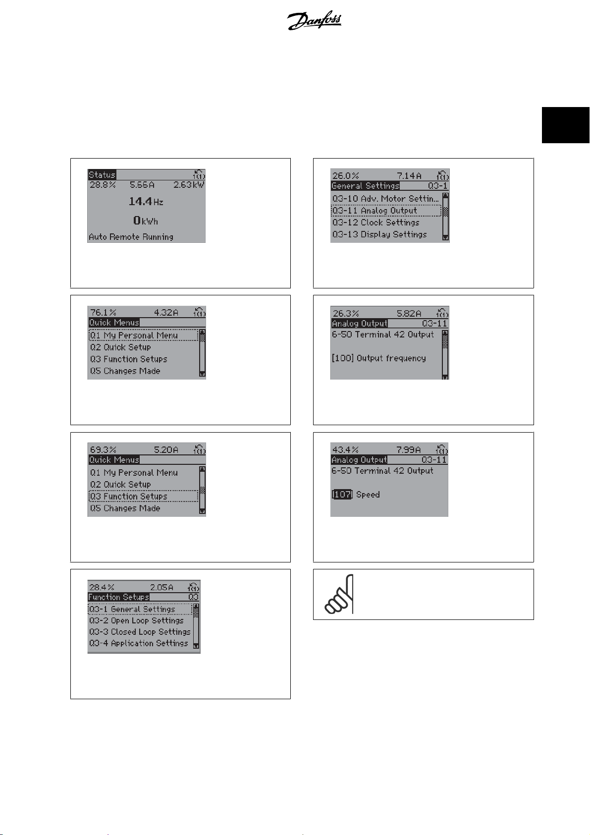
How to access Function Set-up - example
How to change the output on “Analog output 42”
130BT110.1
Illustration 2.7: Step 1: Turn on the frequency converter
(yellow LED lights)
T111.1
130B
Illustration 2.8: Step 2: Press the [Quick Menus] button
(Quick Menus choices appear).
T114.1
130B
Illustration 2.11: Step 5: Use the up/down navigation keys
to scroll down to i.e. 03-11
Illustration 2.12: Step 6: Choose parameter 6-50
42 Output
. Press [OK].
Analog Outputs
130BT115.1
. Press [OK].
Terminal
2
T112.1
130B
Illustration 2.9: Step 3: Use the up/down navigation keys to
scroll down to Function Setups. Press [OK].
T113.1
130B
Illustration 2.10: Step 4: Function Setups choices appear.
Choose 03-1
General Settings
. Press [OK].
T116.1
130B
Illustration 2.13: Step 7: Use the up/down navigation keys
to select between the different choices. Press [OK].
NB!
For the quickest and easiest setup of the AKD102,
please use the AKD Wizard (see chapter
Introduction
)
MG.11.N1.02 - VLT® is a registered Danfoss trademark
25
Page 26
2 How to Programme ADAP-KOOL® Drive Programming Guide
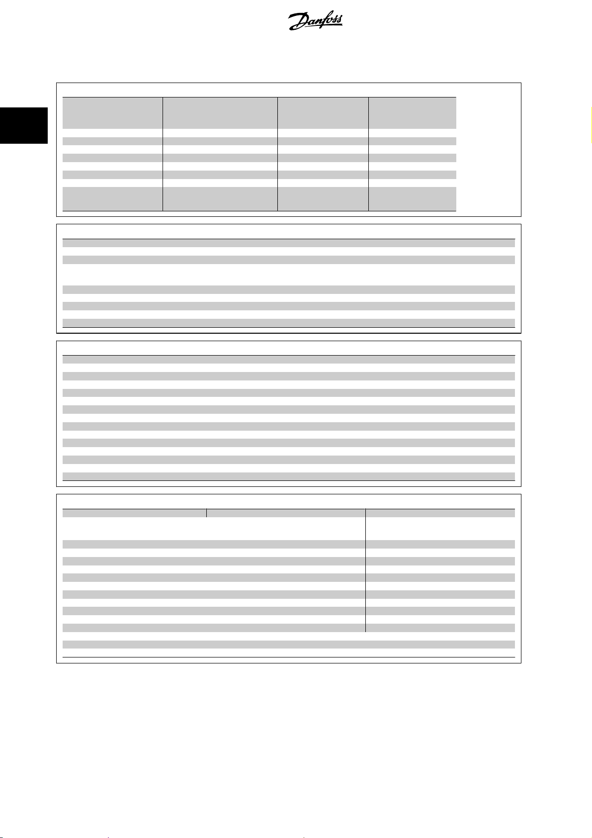
The Function Setup parameters are grouped in the following way:
2
Q3-10 Adv. Motor Settings Q3-11 Analog Output Q3-12 Clock Settings Q3-13 Display Settings
Q3-1 General Settings
1-90 Motor Thermal Protection 6-50 Terminal 42 Output 0-70 Set date and time 0-20 Display Line 1.1 Small
1-93 Thermistor Source 6-51 Terminal 42 Output min. scale 0-71 Date format 0-21 Display Line 1.2 Small
1-29 Automatic Motor Adaption 6-52 Terminal 42 Output max. scale 0-72 Time format 0-22 Display Line 1.3 Small
14-01 Switching Frequency 0-74 DST/Summertime 0-23 Display Line 2 large
0-76 DST/Summertime start 0-24 Display Line 3 large
0-77 DST/Summertime end 0-37 Display Text 1
0-38 Display Text 2
0-39 Display Text 3
Q3-2 Open Loop Settings
1-00 Configuration Mode
3-02 Minimum Reference
3-03 Maximum reference
3-15 Reference 1 Source
6-10 Terminal 53 Low Voltage
6-11 Terminal 53 High Voltage
6-14 Terminal 53 Low Reference / Feedb. value
6-15 Terminal 53 High ref / Feed. value
3-10 Preset reference
Q3-3 Closed Loop Settings
1-00 Configuration mode
20-00 Feedback 1 Source
20-12 Reference/Feedback Unit
6-20 Term 54 low voltage
6-21 Term 54 high voltage
6-22 Terminal 54 Low Current (only visible if switch set to I)
6-23 Terminal 54 High Current (only visible if switch set to I)
6-24 Terminal 54 Low ref / Feedb. value
6-25 Terminal 54 High ref / Feedb. value
3-02 Min. Reference
3-03 Max. Reference
20-21 Setpoint 1
20-93 PID Proportional Gain
20-94 PID Integral Time
3-13 Reference site
Compressor Condenser Single fan/ pump
22-75 Short Cycle Protection
22-76 Interval between Starts 22-41 Minumum sleep time 22-41 Minumum sleep time
22-77 Minimum Run Time 22-42 Wake-up Speed [RPM] 22-42 Wake-up Speed [RPM]
20-00 Feedback 1 Source 22-43 Wake-up Speed [Hz] 22-43 Wake-up Speed [Hz]
20-01 Feedback 1 Conversion 22-44 Wake up ref. /FB difference 22-44 Wake up ref. /FB difference
20-02 Feedback 1 Source Unit 20-00 Feedback 1 Source
20-30 Refrigerant 20-01 Feedback 1 Conversion
20-40 ThermostatPressostat 20-02 Feedback 1 Source Unit
20-41 Cut-out value 20-30 Refrigerant
20-42 Cut-in value 20-40 ThermostatPressostat
25-00 Pack Controller 20-41 Cut-out value
25-06 Number of compressors 20-42 Cut-in value
25-20 Neutral zone
25-21 +zone
25-22 -zone
See also
ADAP-KOOL® Drive AKD102 Programming Guide
22-40 Minimum run time
Q3-4 Application Settings
22-40 Minimum run time
for a detailed description of the Function Setups parameter groups.
26
MG.11.N1.02 - VLT® is a registered Danfoss trademark
Page 27
30BP066.10
30BP067.10
ADAP-KOOL® Drive Programming Guide 2 How to Programme
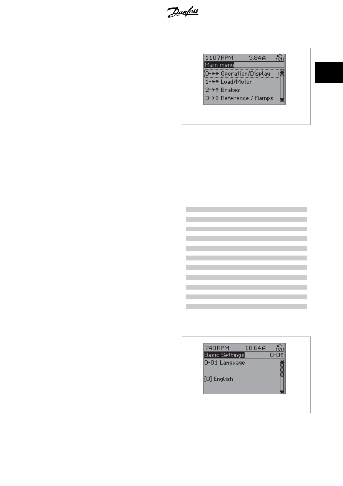
2.1.7 Main Menu Mode
Select the Main Menu mode by pressing the [Main Menu] key. Illustration
6.2 shows the resulting read-out, which appears on the display of the
GLCP.
Lines 2 through 5 on the display show a list of parameter groups which
can be chosen by toggling the up and down buttons.
Illustration 2.14: Display example.
Each parameter has a name and number which remain the same regardless of the programming mode. In the Main Menu mode, the parameters are
divided into groups. The first digit of the parameter number (from the left) indicates the parameter group number.
All parameters can be changed in the Main Menu. The configuration of the unit (par.1-00) will determine other parameters available for programming.
For example, selecting Closed Loop enables additional parameters related to closed loop operation. Option cards added to the unit enable additional
parameters associated with the option device.
1
2
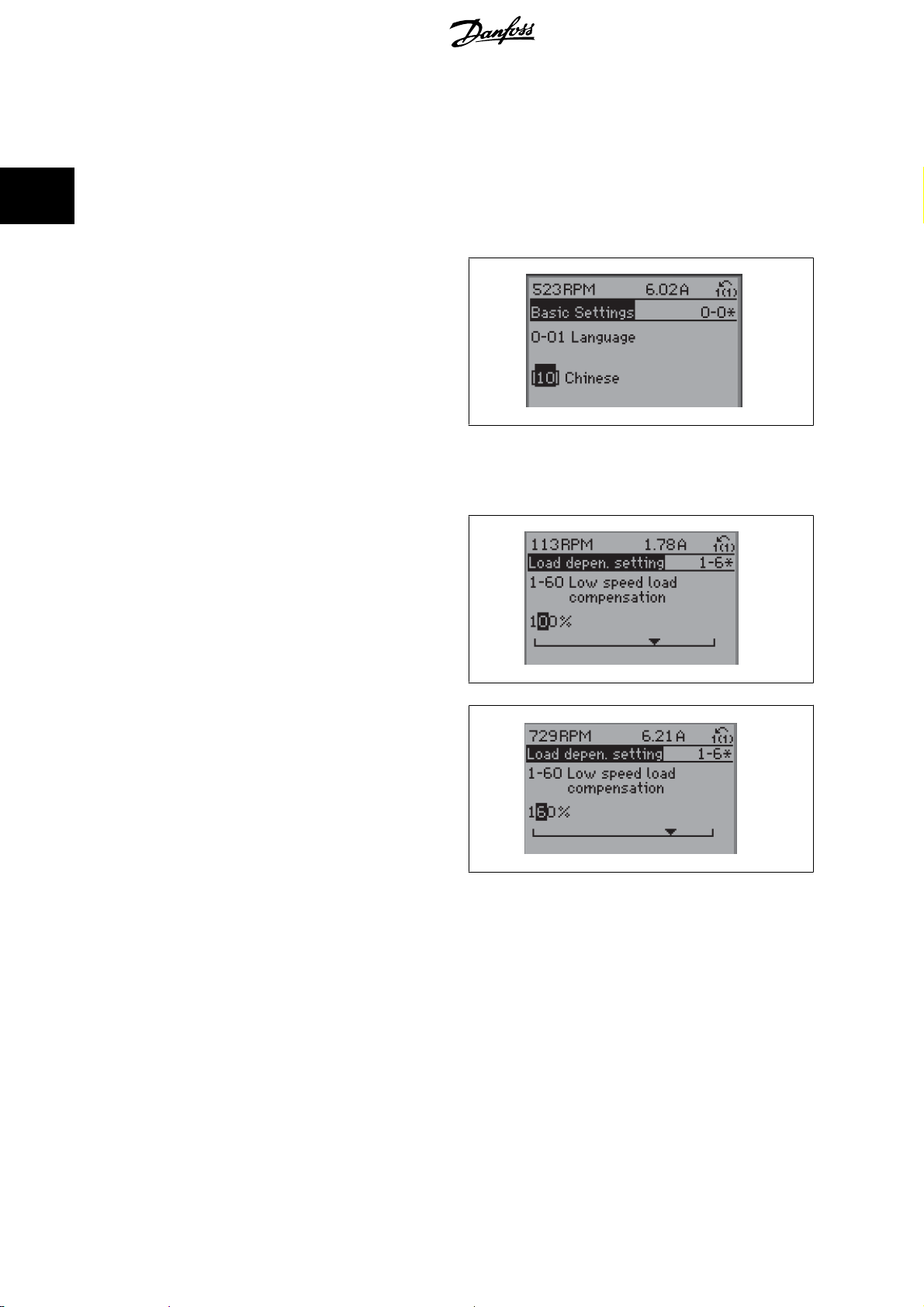
2.1.8 Parameter Selection
In the Main Menu mode, the parameters are divided into groups. Select
a parameter group by means of the navigation keys.
The following parameter groups are accessible:
After selecting a parameter group, choose a parameter by means of the
navigation keys.
The middle section on the GLCP display shows the parameter number and
name as well as the selected parameter value.
Group no. Parameter group:
0 Operation/Display
1Load/Motor
2 Brakes
3 References/Ramps
4 Limits/Warnings
5Digital In/Out
6 Analog In/Out
8 Comm. and Options
11 AKD Lon*
13 Smart Logic
14 Special Functions
15 Drive Information
16 Data Readouts
18 Info & Readouts
20 Internal Control
21 Extended PID
22 Application Functions
23 Time-based Functions
25 Pack Controller
26 Analog I/O Option MCB 109**
28 Compressor functions
* Only when MCA 107 AKLon is installed
**Only when MCB 109 is installed
Table 2.2: Parameter groups.
1
Illustration 2.15: Display example.
MG.11.N1.02 - VLT® is a registered Danfoss trademark
27
Page 28
2
2 How to Programme ADAP-KOOL® Drive Programming Guide
2.1.9 Changing Data
The procedure for changing data is the same whether you select a parameter in the Quick menu or the Main menu mode. Press [OK] to change the
selected parameter.
The procedure for changing data depends on whether the selected parameter represents a numerical data value or a text value.
2.1.10 Changing a Text Value
If the selected parameter is a text value, change the text value by means
] [▼] navigation keys.
of the [
▲
The up key increases the value, and the down key decreases the value.
Place the cursor on the value you want to save and press [OK].
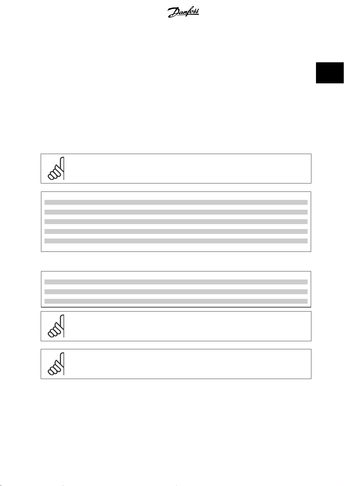
2.1.11 Changing a Group of Numeric Data Values
130BP068.10
If the chosen parameter represents a numeric data value, change the
chosen data value by means of the [
] [▼] navigation keys. Use the [◀] [▶] navigation keys to move
the [
▲
the cursor horizontally.
Use the [▲] [▼] navigation keys to change the data value. The up key
enlarges the data value, and the down key reduces the data value. Place
the cursor on the value you want to save and press [OK].
] [▶] navigation keys as well as
◀
2.1.12 Changing a Data Value, Step-by-Step
Certain parameters can be changed step by step or infinitely varying. This applies to par.1-20
1-23
Motor Frequency
The parameters are changed both as a group of numeric data values and as numeric data values infinitely varying.
.
Motor Power [kW]
, par.1-22
130BP069.10
130BP070.10
Motor Voltage
and par.
2.1.13 Read-out and Programming of Indexed Parameters
Parameters are indexed when placed in a rolling stack.
par.15-30
use the up/down navigation keys to scroll through the value log.
Alarm Log: Error Code
28
to par.15-33
Alarm Log: Date and Time
MG.11.N1.02 - VLT® is a registered Danfoss trademark
contain a fault log which can be read out. Choose a parameter, press [OK], and
Page 29
ADAP-KOOL® Drive Programming Guide 2 How to Programme
Use par.3-10
Choose the parameter, press [OK], and use the up/down navigation keys keys to scroll through the indexed values. To change the parameter value,
select the indexed value and press [OK]. Change the value by using the up/down keys. Press [OK] to accept the new setting. Press [CANCEL] to abort.
Press [Back] to leave the parameter.
Preset Reference
as another example:
2.1.14 Initialisation to Default Settings
Initialise the frequency converter to default settings in two ways:
Recommended initialisation (via par.14-22
1. Select par.14-22
2. Press [OK]
3. Select “Initialisation”
4. Press [OK]
par.14-22
par.14-50
par. 8-30
par.8-31
par.8-32
par.8-35
par.8-36
par.8-37
par.15-00
par.15-20
par.15-30
Operation Mode
RFI Filter
Protocol
Address
Baud Rate
Minimum Response Delay
Maximum Response Delay
Maximum Inter-Char Delay
Operating Hours
Historic Log: Event
Alarm Log: Error Code
Operation Mode
NB!
Resets parameters selected in Personal Menu with default factory setting.
initialises all except:
to par.15-05
to par.15-22
Over Volt's
Historic Log: Time
to par.15-32
Operation Mode
Alarm Log: Time
)
5. Cut off the mains supply and wait until the display turns off.
6. Reconnect the mains supply - the frequency converter is now
reset.
7. Change par.14-22
Operation Mode
back to
Normal Operation
2
.
Manual initialisation
1. Disconnect from mains and wait until the display turns off.
2a. Press [Status] - [Main Menu] - [OK] at the same time while power up for LCP 102, Graphical Display
2b. Press [Menu] while power up for LCP 101, Numerical Display
3. Release the keys after 5 s.
4. The frequency converter is now programmed according to default settings.
This procedure initializes all except: par.15-00
NB!
When you carry out manual initialisation, you also reset serial communication, par.14-50
Removes parameters selected in par. 25-00
NB!
After initialization and power cycling, the display will not show any information until after a couple of minutes.
Operating Hours
Pack Controller
; par.15-03
Power Up's
.
; par.15-04
Over Temp's
RFI Filter
; par.15-05
Over Volt's
and fault log settings.
.
MG.11.N1.02 - VLT® is a registered Danfoss trademark
29
Page 30

3
3 Parameter Description ADAP-KOOL® Drive Programming Guide
30
MG.11.N1.02 - VLT® is a registered Danfoss trademark
Page 31

ADAP-KOOL® Drive Programming Guide 3 Parameter Description
3 Parameter Description
3.1 Parameter Selection
3.1.1 Main Menu Structure
Parameters for the frequency converter are grouped into various parameter groups for easy selection of the correct parameters for optimized operation
of the frequency converter.
The vast majority of ADAP-KOOL Drive AKD 102 applications can be programmed using the Quick Menu button and selecting the parameters under Quick
Setup and Function Setups.
Descriptions and default settings of parameters may be found under the section Parameter Lists at the back of this manual.
0-xx Operation/Display 16-xx Data Readouts
1-xx Load/Motor 18-xx Info & Readouts
2-xx Brakes 20-xx Internal Control
3-xx Reference/Ramps 21-xx Extended PID
4-xx Limits/ Warnings 22-xx Application Functions
5-xx Digital In/Out 23-xx Time Based Functions
6-xx Analog In/Out 24-xx Application Functions 2
8-xx Comm. and Options 25-xx Pack Controller
13-xx Smart Logic Controller 26-xx Analog I/O Option MCB 109*
14-xx Special Functions 28-xx Compressor Functions
* Only when installed
3
3.2 Main Menu - Operation and Display - Group 0
3.2.1 0-** Operation / Display
Parameters related to the fundamental functions of the frequency converter, function of the LCP buttons and configuration of the LCP display.
3.2.2 0-0* Basic Settings
Parameter group for basic frequency converter settings.
0-01 Language
Option: Function:
Defines the language to be used in the display. The frequency converter can be delivered with 4
different language packages. English and German are included in all packages. English cannot be
erased or manipulated.
[0] * English Part of Language packages 1 - 4
[1] Deutsch Part of Language packages 1 - 4
[2] Francais Part of Language package 1
[3] Dansk Part of Language package 1
[4] Spanish Part of Language package 1
[5] Italiano Part of Language package 1
[7] Nederlands Part of Language package 1
MG.11.N1.02 - VLT® is a registered Danfoss trademark
31
Page 32

3 Parameter Description ADAP-KOOL® Drive Programming Guide
0-02 Motor Speed Unit
Option: Function:
This parameter cannot be adjusted while the motor is running.
The display showing depends on settings in par.0-02
tings
. The default setting of par.0-02
which region of the world the frequency converter is supplied to, but can be re-programmed as
required.
Motor Speed Unit
Motor Speed Unit
and par.0-03
and par.0-03
Regional Settings
Regional Set-
depends on
3
NB!
Changing the
It is recommended to select the motor speed unit first, before modifying other
parameters.
[0] RPM Selects display of motor speed variables and parameters (i.e. references, feedbacks and limits) in
terms of motor speed (RPM).
[1] * Hz Selects display of motor speed variables and parameters (i.e. references, feedbacks and limits) in
terms of output frequency to the motor (Hz).
Motor Speed Unit
will reset certain parameters to their initial value.
0-03 Regional Settings
Option: Function:
This parameter cannot be adjusted while the motor is running.
The display showing depends on settings in par.0-02
. The default setting of par.0-02
tings
which region of the world the frequency converter is supplied to but can be re-programmed as
required.
[0] * International Sets par.1-20
[50 Hz].
[1] North America Sets par.1-21
60 Hz.
Motor Power [kW]
Motor Power [HP]
Motor Speed Unit
units to [kW] and the default value of par.1-23
units to HP and the default value of par.1-23
Motor Speed Unit
and par.0-03
and par.0-03
Regional Settings
Motor Frequency
Motor Frequency
Regional Set-
depends on
to
The setting not used is made invisible.
0-04 Operating State at Power-up
Option: Function:
Select the operating mode upon reconnection of the frequency converter to mains voltage after
power down when operating in Hand (local)mode.
[0] * Resume Resumes operation of the frequency converter maintaining the same local reference and the same
start/stop condition (applied by [Hand On]/[Off] on the LCP or Hand Start via a digital input as
before the frequency converter was powered down.
[1] Forced stop, ref=old Uses saved reference [1] to stop the frequency converter but at the same time retain in memory
the local speed reference prior to power down. After mains voltage is reconnected and after re-
ceiving a start command (using the LCP [Hand On] button or Hand Start command via a digital
input) the frequency converter restarts and operates at the retained speed reference.
0-05 Local Mode Unit
Option: Function:
Defines if the local reference unit should be displayed in terms of the motor shaft speed (in RPM/
Hz) or as percent.
[0] * As Motor Speed Unit
[1] %
32
MG.11.N1.02 - VLT® is a registered Danfoss trademark
Page 33

ADAP-KOOL® Drive Programming Guide 3 Parameter Description
3.2.3 0-1* Set-up Operations
Define and control the individual parameter set-ups.
The frequency converter has four parameter setups that can be programmed independently of each other. This makes the frequency converter very
flexible and able to meet the requirements of many different ADAP-KOOL system control schemes often saving the cost of external control equipment.
For example these can be used to program the frequency converter to operate according to one control scheme in one setup (e.g. daytime operation)
and another control scheme in another setup (e.g. night set back). Alternatively they can be used by an AHU or packaged unit OEM to identically program
all their factory fitted frequency converters for different equipment models within a range to have the same parameters and then during production/
commissioning simply select a specific setup depending on which model within that range the frequency converter is installed on.
The active setup (i.e. the setup in which the frequency converter is currently operating) can be selected in parameter 0-10 and is displayed in the LCP.
Using Multi set-up it is possible to switch between set-ups with the frequency converter running or stopped, via digital input or serial communication
commands (e.g. for night set back). If it is necessary to change setups whilst running, ensure parameter 0-12 is programmed as required. For the majority
of ADAP-KOOL applications it will not be necessary to program parameter 0-12 even if change of set up whilst running is required, but for very complex
applications, using the full flexibility of the multiple setups, it may be required. Using parameter 0-11 it is possible to edit parameters within any of the
setups whilst continuing the frequency converter operation in its Active Setup which can be a different setup to that being edited. Using parameter 0-51
it is possible to copy parameter settings between the set-ups to enable quicker commissioning if similar parameter settings are required in different set-
ups.
0-10 Active Set-up
Option: Function:
Select the set-up in which the frequency converter is to operate.
Use par.0-51
of the same parameter within two different set-ups, link the set-ups together using par.0-12
Set-up Linked to
marked ‘not changeable during operation’ have different values.
Parameters which are ‘not changeable during operation’ are marked FALSE in the parameter lists in
the section
Set-up Copy
. Stop the frequency converter before switching between set-ups where parameters
Parameter Lists
to copy a set-up to one or all other set-ups. To avoid conflicting settings
3
This
[0] Factory setup Cannot be changed. It contains the Danfoss data set, and can be used as a data source when
returning the other set-ups to a known state.
[1] * Set-up 1
[2] Set-up 2
[3] Set-up 3
[4] Set-up 4
[9] Multi Set-up Is used for remote selection of set-ups using digital inputs and the serial communication port. This
Set-up 1
[1] to
Set-up 4
[4] are the four separate parameter set-ups within which all parameters
can be programmed.
set-up uses the settings from par.0-12
This Set-up Linked to
.
0-11 Programming Set-up
Option: Function:
Select the set-up to be edited (i.e. programmed) during operation; either the active set-up or one
of the inactive set-ups. The set-up number being edited is displayed in the LCP in (brackets).
[0] Factory setup cannot be edited but it is useful as a data source to return the other set-ups to a known state.
[1] Set-up 1
[2] Set-up 2
[3] Set-up 3
[4] Set-up 4
[9] * Active Set-up (i.e. the set-up in which the frequency converter is operating) can also be edited during operation.
Set-up 1
[1] to
Set-up 4
[4] can be edited freely during operation, independently of the active set-
up.
Editing parameters in the chosen setup would normally be done from the LCP but it is also possible
from any of the serial communication ports.
MG.11.N1.02 - VLT® is a registered Danfoss trademark
33
Page 34

3
3 Parameter Description ADAP-KOOL® Drive Programming Guide
0-12 This Set-up Linked to
Option: Function:
This parameter only needs to be programmed if changing set-ups is required whilst the motor is
running. It ensures that parameters which are "not changeable during operation" have the same
setting in all relevant set-ups.
To enable conflict-free changes from one set-up to another whilst the frequency converter is run-
ning, link set-ups containing parameters which are not changeable during operation. The link will
ensure synchronising of the ‘not changeable during operation’ parameter values when moving from
one set-up to another during operation. ‘Not changeable during operation’ parameters can be iden-
tified by the label FALSE in the parameter lists in the section
The par.0-12
selected. Multi set-up can be used to move from one set-up to another during operation (i.e. while
the motor is running).
Example:
Use Multi set-up to shift from Set-up 1 to Set-up 2 whilst the motor is running. Programme param-
eters in Set-up 1 first, then ensure that Set-up 1 and Set-up 2 are synchronised (or ‘linked’).
Synchronisation can be performed in two ways:
1. Change the edit set-up to
Set-up Linked to
This Set-up Linked to
to
Set-up 1
feature is used when Multi set-up in par.0-10
Set-up 2
[2] in par.0-11
[1]. This will start the linking (synchronising) process.
Parameter Lists
Programming Set-up
.
Active Set-up
and set par.0-12
is
This
OR
2. While still in Set-up 1, using par.0-50
0-12
This Set-up Linked to
to
Set-up 2
[2]. This will start the linking process.
LCP Copy
130BP075.10
, copy Set-up 1 to Set-up 2. Then set par.
130BP076.10
34
After the link is complete, par.0-13
changeable during operation’ parameters are now the same in Set-up 1 and Set-up 2. If there are
changes to a ‘not changeable during operation’ parameter, e.g. par.1-30
Set-up 2, they will also be changed automatically in Set-up 1. A switch between Set-up 1 and Set-
up 2 during operation is now possible.
MG.11.N1.02 - VLT® is a registered Danfoss trademark
Readout: Linked Set-ups
will read {1,2} to indicate that all ‘not
Stator Resistance (Rs)
, in
Page 35

ADAP-KOOL® Drive Programming Guide 3 Parameter Description
[0] * Not linked
[1] Set-up 1
[2] Set-up 2
[3] Set-up 3
[4] Set-up 4
0-13 Readout: Linked Set-ups
Array [5]
Range: Function:
0 N/A* [0 - 255 N/A] View a list of all the set-ups linked by means of par.0-12
one index for each parameter set-up. The parameter value displayed for each index represents
which setups are linked to that parameter setup.
This Set-up Linked to
. The parameter has
3
Index
0 {0}
1 {1,2}
2 {1,2}
3{3}
4 {4}
Table 3.2: Example: Set-up 1 and Set-up 2 are linked
0-14 Readout: Prog. Set-ups / Channel
Range: Function:
0 N/A* [-2147483648 - 2147483647 N/A] View the setting of par.0-11
channels. When the number is displayed in hex, as it is in the LCP, each number represents one
channel.
Numbers 1-4 represent a set-up number; ‘F’ means factory setting; and ‘A’ means active set-up.
The channels are, from right to left: LCP, FC bus, USB, HPFB1.5.
Example: The number AAAAAA21h means that the FC bus selected Set-up 2 in par.0-11
ming Set-up
, the LCP selected Set-up 1 and all others used the active set-up.
3.2.4 0-2* LCP Display
Define the variables displayed in the Graphical Local Control Panel.
LCP value
Programming Set-up
for each of the four different communication
Program-
NB!
Please refer to par.0-37
texts
Display Text 1
, par.0-38
Display Text 2
and par.0-39
Display Text 3
for information on how to write display
0-20 Display Line 1.1 Small
Option: Function:
Select a variable for display in line 1, left position. Default setting is application dependent.
[0] None No display value selected
[37] Display Text 1 Enables an individual text string to be written, for display in the LCP or to be read via serial com-
munication.
[38] Display Text 2 Enables an individual text string to be written, for display in the LCP or to be read via serial com-
munication.
MG.11.N1.02 - VLT® is a registered Danfoss trademark
35
Page 36

3
3 Parameter Description ADAP-KOOL® Drive Programming Guide
[39] Display Text 3 Enables an individual text string to be written, for display in the LCP or to be read via serial com-
munication.
[89] Date and Time Readout Displays the current date and time.
[1501] Running Hours View the number of running hours of the motor.
[1502] kWh Counter View the mains power consumption in kWh.
[1600] Control Word View the Control Word sent from the frequency converter via the serial communication port in hex
code.
[1601] Reference [Unit] Total reference (sum of digital/analog/preset/bus/freeze ref./catch up and slow-down) in selected
unit.
[1602] Reference [%]
[1603] Status Word Present status word
[1605] Main Actual Value [%] View the two-byte word sent with the Status word to the bus Master reporting the Main Actual Value.
[1609] Custom Readout View the user-defined readouts as defined in par.0-30
Readout Min Value
[1610] Power [kW] Actual power consumed by the motor in kW.
[1611] Power [hp] Actual power consumed by the motor in HP.
[1612] Motor Voltage Voltage supplied to the motor.
[1613] Frequency
[1614] Motor Current Phase current of the motor measured as effective value.
[1615] Frequency [%] Motor frequency, i.e. the output frequency from the frequency converter in percent.
[1616] Torque [Nm] Present motor load as a percentage of the rated motor torque.
[1617] Speed [RPM] Motor speed reference. Actual speed will depend on slip compensation being used (compensation
set in par.1-62
minus motor slip.
[1618] Motor Thermal Thermal load on the motor, calculated by the ETR function. See also parameter group 1-9* Motor
Temperature.
[1622] Torque [%] Shows the actual torque produced, in percentage.
[1630] DC Link Voltage Intermediate circuit voltage in the frequency converter.
[1632] Brake Energy /s
[1633] Brake Energy /2 min
[1634] Heatsink Temp. Present heat sink temperature of the frequency converter. The cut-out limit is 95 ± 5° C; cutting
back in occurs at 70 ± 5° C.
and par.0-32
Slip Compensation
Custom Readout Max Value
). If not used, actual speed will be the value read in the display
Custom Readout Unit
.
, par.0-31
Custom
[1635] Inverter Thermal
[1636] Inv. Nom. Current Nominal current of the frequency converter
[1637] Inv. Max. Current Maximum current of the frequency converter
[1638] SL Controller State
[1639] Control Card Temp. Temperature of the control card.
[1650] External Reference Sum of the external reference as a percentage, i.e. the sum of analog/pulse/bus.
[1652] Feedback [Unit] Reference value from programmed digital input(s).
[1653] Digi Pot Reference View the contribution of the digital potentiometer to the actual reference Feedback.
[1654] Feedback 1 [Unit] View the value of Feedback 1. See also par. 20-0*.
[1655] Feedback 2 [Unit] View the value of Feedback 2. See also par. 20-0*.
36
MG.11.N1.02 - VLT® is a registered Danfoss trademark
Page 37

ADAP-KOOL® Drive Programming Guide 3 Parameter Description
[1656] Feedback 3 [Unit] View the value of Feedback 3. See also par. 20-0*.
[1660] Digital Input Displays the status of the digital inputs. Signal low = 0; Signal high = 1.
Regarding order, see par.16-60
[1661] Terminal 53 Switch Setting Setting of input terminal 53. Current = 0; Voltage = 1.
[1662] Analog Input 53 Actual value at input 53 either as a reference or protection value.
[1663] Terminal 54 Switch Setting Setting of input terminal 54. Current = 0; Voltage = 1.
Digital Input
. Bit 0 is at the extreme right.
[1664] Analog Input 54 Actual value at input 54 either as reference or protection value.
[1665] Analog Output 42 [mA] Actual value at output 42 in mA. Use par.6-50
represented by output 42.
[1666] Digital Output [bin] Binary value of all digital outputs.
[1667] Pulse Input #29 [Hz]
[1668] Pulse Input #33 [Hz]
[1669] Pulse Output #27 [Hz] Actual value of pulses applied to terminal 27 in digital output mode.
[1670] Pulse Output #29 [Hz] Actual value of pulses applied to terminal 29 in digital output mode.
[1671] Relay Output [bin] View the setting of all relays.
[1672] Counter A View the present value of Counter A.
[1673] Counter B View the present value of Counter B.
[1675] Analog In X30/11
[1676] Analog In X30/12
[1677] Analog Out X30/8 [mA]
[1680] Fieldbus CTW 1 Control word (CTW) received from the Bus Master.
[1682] Fieldbus REF 1 Main reference value sent with control word via the serial communications network e.g. from the
BMS, PLC or other master controller.
[1684] Comm. Option STW Extended fieldbus communication option status word.
Terminal 42 Output
to select the variable to be
3
[1685] FC Port CTW 1 Control word (CTW) received from the Bus Master.
[1686] FC Port REF 1 Status word (STW) sent to the Bus Master.
[1690] Alarm Word One or more alarms in a Hex code (used for serial communications)
[1691] Alarm Word 2 One or more alarms in a Hex code (used for serial communications)
[1692] Warning Word One or more warnings in a Hex code (used for serial communications)
[1693] Warning Word 2 One or more warnings in a Hex code (used for serial communications)
[1694] Ext. Status Word One or more status conditions in a Hex code (used for serial communications)
[1695] Ext. Status Word 2 One or more status conditions in a Hex code (used for serial communications)
[1696] Maintenance Word The bits reflect the status for the programmed Preventive Maintenance Events in parameter group
23-1*
[1830] Analog Input X42/1 Shows the value of the signal applied to terminal X42/1 on the Analog I/O card.
[1831] Analog Input X42/3 Shows the value of the signal applied to terminal X42/3 on the Analog I/O card.
[1832] Analog Input X42/5 Shows the value of the signal applied to terminal X42/5 on the Analog I/O card.
[1833] Analog Out X42/7 [V] Shows the value of the signal applied to terminal X42/7 on the Analog I/O card.
[1834] Analog Out X42/9 [V] Shows the value of the signal applied to terminal X42/9 on the Analog I/O card.
[1835] Analog Out X42/11 [V] Shows the value of the signal applied to terminal X42/11 on the Analog I/O card.
MG.11.N1.02 - VLT® is a registered Danfoss trademark
37
Page 38

3
3 Parameter Description ADAP-KOOL® Drive Programming Guide
[2117] Ext. 1 Reference [Unit] The value of the reference for extended Closed Loop Controller 1
[2118] Ext. 1 Feedback [Unit] The value of the feedback signal for extended Closed Loop Controller 1
[2119] Ext. 1 Output [%] The value of the output from extended Closed Loop Controller 1
[2137] Ext. 2 Reference [Unit] The value of the reference for extended Closed Loop Controller 2
[2138] Ext. 2 Feedback [Unit] The value of the feedback signal for extended Closed Loop Controller 2
[2139] Ext. 2 Output [%] The value of the output from extended Closed Loop Controller 2
[2157] Ext. 3 Reference [Unit] The value of the reference for extended Closed Loop Controller 3
[2158] Ext. 3 Feedback [Unit] The value of the feedback signal for extended Closed Loop Controller 3
[2159] Ext. 3 Output [%] The value of the output from extended Closed Loop Controller 3
[2230] No-Flow Power The calculated No Flow Power for the actual operating speed
[2580] Pack Status
[2581] Compressor Status
[2587] Inverse Interlock
[2827] Discharge Temperature
[3110] Bypass Status Word
[3111] Bypass Running Hours
[11675] Wizard Init State
NB!
Please consult the
ADAP-KOOL Drive AKD 102 Programming Guide, MG.11.CX.YY
0-21 Display Line 1.2 Small
Option: Function:
Application Dependent Select a variable for display in line 1, middle position. The options are the same as listed for par.
0-20.
0-22 Display Line 1.3 Small
Option: Function:
Application Dependent Select a variable for display in line 1, right position. The options are the same as listed for par. 0-20.
0-23 Display Line 2 Large
Option: Function:
Application Dependent Select a variable for display in line 2. The options are the same as listed for par. 0-20.
0-24 Display Line 3 Large
Option: Function:
Application Dependent Select a variable for display in line 3. The options are the same as listed for par. 0-20.
3.2.5 0-3*LCP Custom Readout
for detailed information.
It is possible to customize the display elements for various purposes: *Custom Readout. Value proportional to speed (Linear, squared or cubed depending
on unit selected in par.0-30
Custom Readout
The calculated value to be displayed is based on settings in par.0-30
0-32
Custom Readout Max Value
38
Custom Readout Unit
, par.4-13
Motor Speed High Limit [RPM]
) *Display Text. Text string stored in a parameter.
Custom Readout Unit
, par.4-14
MG.11.N1.02 - VLT® is a registered Danfoss trademark
, par.0-31
Motor Speed High Limit [Hz]
Custom Readout Min Value
and actual speed.
(linear only), par.
Page 39

ADAP-KOOL® Drive Programming Guide 3 Parameter Description
3
The relation will depend on the type of unit selected in par.0-30
Unit Type
Dimensionless Linear
Speed
Flow, volume
Flow, mass
Velocity
Length
Temperature
Pressure Quadratic
Power Cubic
Custom Readout Unit
Speed Relation
0-30 Custom Readout Unit
Option: Function:
Program a value to be shown in the display of the LCP. The value has a linear, squared or cubed
relation to speed. This relation depends on the unit selected (see table above). The actual calculated
value can be read in par.16-09
Readout [16-09] in par.0-20
[0]
[1] * %
[5] PPM
[10] 1/min
[11] RPM
[12] Pulse/s
[20] l/s
[21] l/min
[22] l/h
[23] m³/s
[24] m³/min
[25] m³/h
[30] kg/s
[31] kg/min
[32] kg/h
:
Custom Readout
Display Line 1.1 Small
, and/or shown in the display be selecting Custom
to par. 0-24
Display Line 3 Large
.
MG.11.N1.02 - VLT® is a registered Danfoss trademark
39
Page 40

3
3 Parameter Description ADAP-KOOL® Drive Programming Guide
[33] t/min
[34] t/h
[40] m/s
[41] m/min
[45] m
[60] °C
[70] mbar
[71] bar
[72] Pa
[73] kPa
[74] m WG
[80] kW
[120] GPM
[121] gal/s
[122] gal/min
[123] gal/h
[124] CFM
[125] ft³/s
[126] ft³/min
[127] ft³/h
[130] lb/s
[131] lb/min
[132] lb/h
[140] ft/s
[141] ft/min
[145] ft
[160] °F
[170] psi
[171] lb/in²
[172] in WG
[173] ft WG
[180] HP
0-31 Custom Readout Min Value
Range: Function:
0 Custom-
ReadoutU-
nit*
[0 - 0 CustomReadoutUnit] This parameter allows the choice of the min. value of the custom defined readout (occurs at zero
speed). It is only possible to select a value different to 0 when selecting a linear unit in par.
Custom Readout Unit
0-30
0-32 Custom Readout Max Value
Range: Function:
100.00 Cus-
tomReadou-
tUnit*
40
[par. 0-31 - 999999.99 CustomRea-
doutUnit]
This parameter sets the max value to be shown when the speed of the motor has reached the set
value for par.4-13
on setting in par. 0-02).
MG.11.N1.02 - VLT® is a registered Danfoss trademark
. For Quadratic and Cubic units the minimum value will be 0.
Motor Speed High Limit [RPM]
or par.4-14
Motor Speed High Limit [Hz]
(depends
Page 41

ADAP-KOOL® Drive Programming Guide 3 Parameter Description
0-37 Display Text 1
Range: Function:
0 N/A* [0 - 0 N/A] In this parameter it is possible to write an individual text string for display in the LCP or to be read
via serial communication. If to be displayed permanently select Display Text 1 in par.0-20
Line 1.1 Small
Line 2 Large
character. Use the
cursor, it can be changed. Use the
can be inserted by placing the cursor between two characters and pressing
, par. 0-21
or par. 0-24
Display Line 1.2 Small
Display Line 3 Large
and ▶ buttons to move the cursor. When a character is highlighted by the
◀
▲
, par. 0-22
. Use the ▲ or ▼ buttons on the LCP to change a
or ▼ buttons on the LCP to change a character. A character
Display Line 1.3 Small
▲
, par. 0-23
or ▼.
0-38 Display Text 2
Range: Function:
0 N/A* [0 - 0 N/A] In this parameter it is possible to write an individual text string for display in the LCP or to be read
via serial communication. If to be displayed permanently select Display Text 2 in par.0-20
Line 1.1 Small
Line 2 Large
character. Use the
cursor, this character can be changed. A character can be inserted by placing the cursor between
two characters and pressing
, par. 0-21
or par. 0-24
Display Line 1.2 Small
Display Line 3 Large
and ▶ buttons to move the cursor. When a character is highlighted by the
◀
or ▼.
▲
, par. 0-22
. Use the ▲ or ▼ buttons on the LCP to change a
Display Line 1.3 Small
, par. 0-23
Display
Display
3
Display
Display
0-39 Display Text 3
Range: Function:
0 N/A* [0 - 0 N/A] In this parameter it is possible to write an individual text string for display in the LCP or to be read
via serial communication. If to be displayed permanently select Display Text 3 in par.0-20
Line 1.1 Small
Line 2 Large
character. Use the
cursor, this character can be changed. A character can be inserted by placing the cursor between
two characters and pressing
,par. 0-21
or par. 0-24
Display Line 1.2 Small
Display Line 3 Large
and ▶ buttons to move the cursor. When a character is highlighted by the
◀
or ▼.
▲
, par. 0-22
. Use the ▲ or ▼ buttons on the LCP to change a
Display Line 1.3 Small
, par. 0-23
Display
Display
3.2.6 LCP Keypad, 0-4*
Enable, disable and password protect individual keys on the LCP.
0-40 [Hand on] Key on LCP
Option: Function:
[0] Disabled No function
[1] * Enabled [Hand on] Key enabled
[2] Password Avoid unauthorized start in Hand mode. If par.0-40
Personal Menu, then define the password in par.0-65
the password in par.0-60
Main Menu Password
[Hand on] Key on LCP
Personal Menu Password
.
is included in the My
. Otherwise define
0-41 [Off] Key on LCP
Option: Function:
[0] Disabled No function
[1] * Enabled [Off] Key is enabled
[2] Password Avoid unauthorized stop. If par.0-41
define the password in par.0-65
0-60
Main Menu Password
MG.11.N1.02 - VLT® is a registered Danfoss trademark
Personal Menu Password
.
[Off] Key on LCP
is included in the My Personal Menu, then
. Otherwise define the password in par.
41
Page 42

3 Parameter Description ADAP-KOOL® Drive Programming Guide
0-42 [Auto on] Key on LCP
Option: Function:
[0] Disabled No function
[1] * Enabled [Auto on] Key is enabled
3
[2] Password Avoid unauthorized start in Auto mode. If par.0-42
Personal Menu, then define the password in par.0-65
the password in par.0-60
Main Menu Password
[Auto on] Key on LCP
Personal Menu Password
.
is included in the My
. Otherwise define
0-43 [Reset] Key on LCP
Option: Function:
[0] Disabled No function
[1] * Enabled [Reset] Key is enabled
[2] Password Avoid unauthorized resetting. If par.0-43
Menu
, then define the password in par.0-65
word in par.0-60
Main Menu Password
[Reset] Key on LCP
Personal Menu Password
.
is included in the par. 0-25
. Otherwise define the pass-
My Personal
3.2.7 0-5* Copy / Save
Copy parameter settings between set-ups and to/from the LCP.
0-50 LCP Copy
Option: Function:
[0] * No copy No function
[1] All to LCP Copies all parameters in all set-ups from the frequency converter memory to the LCP memory. For
service purposes it is recommended to copy all parameters to the LCP after commissioning.
[2] All from LCP Copies all parameters in all set-ups from the LCP memory to the frequency converter memory.
[3] Size indep. from LCP Copies only the parameters that are independent of the motor size. The latter selection can be used
to programme several frequency converters with the same function without disturbing motor data
which are already set.
This parameter cannot be adjusted while the motor is running.
0-51 Set-up Copy
Option: Function:
[0] * No copy No function
[1] Copy to set-up 1 Copies all parameters in the present Programming Set-up (defined in par.0-11
) to Set-up 1.
up
[2] Copy to set-up 2 Copies all parameters in the present Programming Set-up (defined in par.0-11
) to Set-up 2.
up
[3] Copy to set-up 3 Copies all parameters in the present Programming Set-up (defined in par.0-11
up
) to Set-up 3.
[4] Copy to set-up 4 Copies all parameters in the present Programming Set-up (defined in par.0-11
) to Set-up 4.
up
[9] Copy to all Copies the parameters in the present set-up over to each of the set-ups 1 to 4.
Programming Set-
Programming Set-
Programming Set-
Programming Set-
3.2.8 0-6* Password
Define password access to menus.
42
MG.11.N1.02 - VLT® is a registered Danfoss trademark
Page 43

ADAP-KOOL® Drive Programming Guide 3 Parameter Description
0-60 Main Menu Password
Range: Function:
100 N/A* [0 - 999 N/A] Define the password for access to the Main Menu via the [Main Menu] key. If par.0-61
Main Menu w/o Password
is set to
Full access
[0], this parameter will be ignored.
Access to
0-61 Access to Main Menu w/o Password
Option: Function:
[0] * Full access Disables password defined in par.0-60
Main Menu Password
.
3
[1] Read only Prevent unauthorized editing of Main Menu parameters.
[2] No access Prevent unauthorized viewing and editing of Main Menu parameters.
Full access
If
word
[0] is selected then par.0-60
will be ignored.
Main Menu Password
, par.0-65
Personal Menu Password
and par.0-66
Access to Personal Menu w/o Pass-
0-65 Personal Menu Password
Range: Function:
200 N/A* [0 - 999 N/A] Define the password for access to the My Personal Menu via the [Quick Menu] key. If par.
0-66
Access to Personal Menu w/o Password
is set to
Full access
[0], this parameter will be ignored.
0-66 Access to Personal Menu w/o Password
Option: Function:
[0] * Full access Disables password defined in par.0-65
[1] Read only Prevents unauthorized editing of My Personal Menu parameters.
[2] No access Prevents unauthorized viewing and editing of My Personal Menu parameters.
If par.0-61
Access to Main Menu w/o Password
is set to
Full access
[0], this parameter will be ignored.
Personal Menu Password
.
3.2.9 Clock Settings, 0-7*
Set the time and date of the internal clock. The internal clock can be used for e.g. Timed Actions, energy log, Trend Analysis, date/time stamps on alarms,
Logged data and Preventive Maintenance.
It is possible to program the clock for Daylight Saving Time / summertime, weekly working days/non-working days including 20 exceptions (holidays
etc.). Although the clock settings can be set via the LCP, they can also be set along with timed actions and preventative maintenance functions using the
MCT10 software tool.
NB!
The frequency converter has no back up of the clock function and the set date/time will reset to default (2000-01-01 00:00) after a
power down unless a Real Time Clock module with back up is installed. If no module with back up is installed, it is recommended the
clock function is only used if the frequency converter is integrated into the BMS using serial communications, with the BMS maintaining
synchronization of control equipment clock times. In par.0-79
been set properly, e.g. after a power down.
NB!
If mounting an Analog I/O MCB 109 option card, a battery back-up of the date and time is included.
Clock Fault
it is possible to program for a Warning in case clock has not
0-70 Set Date and Time
Range: Function:
0 N/A* [0 - 0 N/A] Sets the date and time of the internal clock. The format to be used is set in par.0-71
and par.0-72
MG.11.N1.02 - VLT® is a registered Danfoss trademark
Time Format
.
Date Format
43
Page 44

3 Parameter Description ADAP-KOOL® Drive Programming Guide
0-71 Date Format
Option: Function:
Sets the date format to be used in the LCP.
[0] * YYYY-MM-DD
[1] * DD-MM-YYYY
[2] MM/DD/YYYY
3
0-72 Time Format
Option: Function:
Sets the time format to be used in the LCP.
[0] * 24 h
[1] 12 h
0-74 DST/Summertime
Option: Function:
Choose how Daylight Saving Time/Summertime should be handled. For manual DST/Summertime
[0] * Off
[2] Manual
enter the start date and end date in par.0-76
.
End
DST/Summertime Start
and par.0-77
DST/Summertime
0-76 DST/Summertime Start
Range: Function:
0 N/A* [0 - 0 N/A] Sets the date and time when summertime/DST starts. The date is programmed in the format se-
lected in par.0-71
Date Format
.
0-77 DST/Summertime End
Range: Function:
0 N/A* [0 - 0 N/A] Sets the date and time when summertime/DST ends. The date is programmed in the format selected
in par.0-71
Date Format
.
0-79 Clock Fault
Option: Function:
Enables or disables the clock warning, when the clock has not been set or has been reset due to a
power-down and no backup is installed.
[0] * Disabled
[1] Enabled
0-81 Working Days
Array with 7 elements [0] - [6] displayed below parameter number in display. Press OK and step between elements by means of ▲ and ▼ buttons on
the LCP.
Option: Function:
Set for each weekday if it is a working day or a non-working day. First element of the array is
Monday. The working days are used for Timed Actions.
[0] * No
[1] Yes
44
MG.11.N1.02 - VLT® is a registered Danfoss trademark
Page 45

ADAP-KOOL® Drive Programming Guide 3 Parameter Description
0-82 Additional Working Days
Array with 5 elements [0] - [4] displayed below parameter number in display. Press OK and step between elements by means of ▲ and▼ buttons on
the LCP.
Range: Function:
0 N/A* [0 - 0 N/A] Defines dates for additional working days that normally would be non-working days according to
par.0-82
Additional Working Days
.
0-83 Additional Non-Working Days
Array with 15 elements [0] - [14] displayed below parameter number in display. Press OK and step between elements by means of ▲ and▼ buttons
on the LCP.
Range: Function:
0 N/A* [0 - 0 N/A] Defines dates for additional working days that normally would be non-working days according to
par.0-81
Working Days
.
0-89 Date and Time Readout
Range: Function:
0 N/A* [0 - 0 N/A] Displays the current date and time. The date and time is updated continuously.
The clock will not begin counting until a setting different from default has been made in par.
0-70
Set Date and Time
.
3
MG.11.N1.02 - VLT® is a registered Danfoss trademark
45
Page 46

3
3 Parameter Description ADAP-KOOL® Drive Programming Guide
3.3 Main Menu - Load and Motor - Group 1
3.3.1 General Settings, 1-0*
Define whether the frequency converter operates in open loop or closed loop.
1-00 Configuration Mode
Option: Function:
[0] * Speed Open Loop
[3] Process Closed Loop
NB!
This parameter cannot be changed when motor is running.
NB!
When set for Closed Loop, the commands Reversing and Start Reversing will not reverse the direction of the motor.
1-03 Torque Characteristics
Option: Function:
[0] * Compressor CT For speed control of screw and scroll compressors. Provides a voltage which is optimized for a
constant torque load characteristic of the motor in the entire range down to 15 Hz.
[1] Condenser VT For speed control of centrifugal pumps and fans. Also to be used when controlling more than one
motor from the same frequency converter (e.g. multiple condenser fans or cooling tower fans).
Provides a voltage which is optimized for a squared torque load characteristic of the motor.
[2] Compressor AEO CT
[3] Single fan/ pump AEO
Auto Energy Optimization Compressor
scroll compressors. Provides a voltage which is optimized for a constant torque load characteristic
of the motor in the entire range down to 15Hz but in addition the AEO feature will adapt the voltage
exactly to the current load situation, thereby reducing energy consumption and audible noise from
the motor. To obtain optimal performance, the motor power factor cos phi must be set correctly.
This value is set in par. 14-43, Motor cos phi. The parameter has a default value which is automat-
ically adjusted when the motor data is programmed. These settings will typically ensure optimum
motor voltage but if the motor power factor cos phi requires tuning, an AMA function can be carried
out using par. 1-29, Automatic Motor Adaptation (AMA). It is very rarely necessary to adjust the
motor power factor parameter manually.
Auto Energy Optimization VT
fans. Provides a voltage which is optimized for a squared torque load characteristic of the motor
but in addition the AEO feature will adapt the voltage exactly to the current load situation, thereby
reducing energy consumption and audible noise from the motor. To obtain optimal performance,
the motor power factor cos phi must be set correctly. This value is set in par. 14-43, Motor cos phi.
The parameter has a default value and is automatically adjusted when the motor data is program-
med. These settings will typically ensure optimum motor voltage but if the motor power factor cos
phi requires tuning, an AMA function can be carried out using par. 1-29, Automatic Motor Adaptation
(AMA). It is very rarely necessary to adjust the motor power factor parameter manually.
. For optimum energy efficient speed control of centrifugal pumps and
. For optimum energy efficient speed control of screw and
3.3.2 1-2* Motor Data
Parameter group 1-2* comprises input data from the nameplate on the connected motor.
Parameters in parameter group 1-2* cannot be adjusted while the motor is running.
46
MG.11.N1.02 - VLT® is a registered Danfoss trademark
Page 47

ADAP-KOOL® Drive Programming Guide 3 Parameter Description
NB!
Changing the value of these parameters affects the setting of other parameters.
1-20 Motor Power [kW]
Range: Function:
4.00 kW* [0.09 - 3000.00 kW] Enter the nominal motor power in kW according to the motor nameplate data. The default value
corresponds to the nominal rated output of the unit.
This parameter cannot be adjusted while the motor is running. Depending on the choices made in
par.0-03
Regional Settings
invisible.
, either par.1-20
Motor Power [kW]
or par.1-21
Motor Power [HP]
is made
1-21 Motor Power [HP]
Range: Function:
4.00 hp* [0.09 - 3000.00 hp] Enter the nominal motor power in HP according to the motor nameplate data. The default value
corresponds to the nominal rated output of the unit.
This parameter cannot be adjusted while the motor is running.
Depending on the choices made in par.0-03
or par.1-21
Motor Power [HP]
is made invisible.
Regional Settings
, either par.1-20
Motor Power [kW]
3
1-22 Motor Voltage
Range: Function:
500. V* [10. - 1000. V] Enter the nominal motor voltage according to the motor nameplate data. The default value corre-
sponds to the nominal rated output of the unit.
This parameter cannot be adjusted while the motor is running.
1-23 Motor Frequency
Range: Function:
50. Hz* [20 - 1000 Hz] Select the motor frequency value from the motor nameplate data.For 87 Hz operation with 230/400
V motors, set the nameplate data for 230 V/50 Hz. Adapt par.4-13
and par.3-03
NB!
This parameter cannot be adjusted while the motor is running.
Maximum Reference
to the 87 Hz application.
Motor Speed High Limit [RPM]
1-24 Motor Current
Range: Function:
7.20 A* [0.10 - 10000.00 A] Enter the nominal motor current value from the motor nameplate data. This data is used for cal-
culating motor torque, motor thermal protection etc.
NB!
This parameter cannot be adjusted while the motor is running.
1-25 Motor Nominal Speed
Range: Function:
1420. RPM* [100 - 60000 RPM] Enter the nominal motor speed value from the motor nameplate data. This data is used for calcu-
lating automatic motor compensations.
MG.11.N1.02 - VLT® is a registered Danfoss trademark
47
Page 48

3
3 Parameter Description ADAP-KOOL® Drive Programming Guide
NB!
This parameter cannot be changed while the motor is running.
1-28 Motor Rotation Check
Option: Function:
Following installation and connection of the motor, this function allows the correct motor rotation
direction to be verified. Enabling this function overrides any bus commands or digital inputs, except
External Interlock and Safe Stop (if included).
[0] * Off Motor Rotation Check is not active.
[1] Enabled Motor Rotation Check is enabled. Once enabled, Display shows:
“Note! Motor may run in wrong direction”.
Pressing [OK], [Back] or [Cancel] will dismiss the message and display a new message: “Press [Hand on] to start the motor. Press [Cancel] to abort”.
Pressing [Hand on] starts the motor at 5 Hz in forward direction and the display shows: “Motor is running. Check if motor rotation direction is correct.
Press [Off] to stop the motor”. Pressing [Off] stops the motor and resets par.1-28
motor phase cables should be interchanged. IMPORTANT:
Motor Rotation Check
. If motor rotation direction is incorrect, two
Mains power must be removed before disconnecting motor phase cables.
1-29 Automatic Motor Adaptation (AMA)
Option: Function:
The AMA function optimizes dynamic motor performance by automatically optimizing the advanced
motor parameters par.1-30
is stationary.
[0] * Off No function
[1] Enable complete AMA performs AMA of the stator resistance R
the rotor leakage reactance X
[2] Enable reduced AMA performs a reduced AMA of the stator resistance R
filter is used between the frequency converter and the motor.
Activate the AMA function by pressing [Hand on] after selecting [1] or [2]. See also the section
the display will read: “Press [OK] to finish AMA”. After pressing the [OK] key the frequency converter is ready for operation.
Note:
• For the best adaptation of the frequency converter, run AMA on a cold motor
• AMA cannot be performed while the motor is running
Stator Resistance (Rs)
and the main reactance Xh.
2
to par.1-35
, the rotor resistance Rr, the stator leakage reactance X1,
S
Automatic Motor Adaptation
Main Reactance (Xh)
in the system only. Select this option if an LC
s
) while the motor
. After a normal sequence,
48
NB!
It is important to set motor par. 1-2* Motor Data correctly, since these form part of the AMA algorithm. An AMA must be performed
to achieve optimum dynamic motor performance. It may take up to 10 min., depending on motor power rating.
NB!
Avoid generating external torque during AMA
MG.11.N1.02 - VLT® is a registered Danfoss trademark
Page 49

ADAP-KOOL® Drive Programming Guide 3 Parameter Description
NB!
If one of the settings in par. 1-2* Motor Data is changed, par.1-30
parameters, will return to default setting.
This parameter cannot be adjusted while the motor is running
NB!
Full AMA should be run without filter only while reduced AMA should be run with filter.
Stator Resistance (Rs)
to par.1-39
Motor Poles
, the advanced motor
3
See section:
Application Examples > Automatic Motor Adaptation
in the Design Guide.
3.3.3 1-3* Adv. Motor Data
Parameters for advanced motor data. The motor data in par.1-30
to run the motor optimally. The default settings are figures based on common motor parameter values from normal standard motors. If the motor
parameters are not set correctly, a malfunction of the frequency converter system may occur. If the motor data is not known, running an AMA (Automatic
Motor Adaptation) is recommended. See the
of inertia of the rotor and the iron loss resistance (par.1-36
Par. 1-3* and par. 1-4* cannot be adjusted while the motor is running.
Illustration 3.1: Motor equivalent diagram for an asynchro nous motor
Automatic Motor Adaptation
1-30 Stator Resistance (Rs)
Range: Function:
1.4000
Ohm*
[0.0140 - 140.0000 Ohm] Set the stator resistance value. Enter the value from a motor data sheet or perform an AMA on a
cold motor. This parameter cannot be adjusted while the motor is running.
Stator Resistance (Rs)
section. The AMA sequence will adjust all motor parameters except the moment
Iron Loss Resistance (Rfe)
to par.1-39
).
Motor Poles
must match the relevant motor in order
1-35 Main Reactance (Xh)
Range: Function:
100.0000
Ohm*
[1.0000 - 10000.0000 Ohm] Set the main reactance of the motor using one of these methods:
1. Run an AMA on a cold motor. The frequency converter will measure the value from the
motor.
2. Enter the X
3. Use the X
the motor name plate data.
NB!
This parameter cannot be adjusted while running.
MG.11.N1.02 - VLT® is a registered Danfoss trademark
value manually. Obtain the value from the motor supplier.
h
default setting. The frequency converter establishes the setting on the basis of
h
49
Page 50

3 Parameter Description ADAP-KOOL® Drive Programming Guide
1-36 Iron Loss Resistance (Rfe)
Range: Function:
10000.000
Ohm*
[0 - 10000.000 Ohm] Enter the equivalent iron loss resistance (RFe) value to compensate for iron losses in the motor.
The R
value cannot be found by performing an AMA.
Fe
value is especially important in torque control applications. If RFe is unknown, leave par.
The R
Fe
1-36
Iron Loss Resistance (Rfe)
on default setting.
3
NB!
This parameter cannot be adjusted while the motor is running.
1-39 Motor Poles
Range: Function:
4. N/A* [2 - 100 N/A] Enter the number of motor poles.
Poles ~n
2 2700 - 2880 3250 - 3460
4 1350 - 1450 1625 - 1730
6 700 - 960 840 - 1153
The table shows the number of poles for normal speed ranges of various motor types. Define motors
designed for other frequencies separately. The motor pole value is always an even number, because
it refers to the total number of poles, not pairs of poles. The frequency converter creates the initial
setting of par.1-39
1-25
Motor Nominal Speed Motor Nominal Speed
This parameter cannot be adjusted while the motor is running.
@ 50 Hz ~nn@60 Hz
n
Motor Poles
3.3.4 1-5* Load Indep. Setting
Parameters for setting the load-independent motor settings.
based on par.1-23
.
Motor Frequency Motor Frequency
and par.
1-51 Min Speed Normal Magnetising [RPM]
Range: Function:
15. RPM* [10 - 300 RPM] Set the required speed for normal magnetising current. If the speed is set lower than the motor slip
speed, par. 1-50
are of no significance.
[RPM]
Use this parameter along with par. 1-50
par. 1-50
Motor Magnetisation at Zero Speed
Motor Magnetisation at Zero Speed
and par.1-51
Motor Magnetisation at Zero Speed
.
Min Speed Normal Magnetising
. See drawing for
1-52 Min Speed Normal Magnetising [Hz]
Range: Function:
0.5 Hz* [0.3 - 10.0 Hz] Set the required frequency for normal magnetising current. If the frequency is set lower than the
motor slip frequency, par. 1-50
Magnetising [RPM]
Use this parameter along with par. 1-50
par. 1-50
are inactive.
Motor Magnetisation at Zero Speed
Motor Magnetisation at Zero Speed
Motor Magnetisation at Zero Speed
.
and par.1-51
Min Speed Normal
. See drawing for
3.3.5 1-6* Load Depend. Setting
Parameters for adjusting the load-dependent motor settings.
50
MG.11.N1.02 - VLT® is a registered Danfoss trademark
Page 51

ADAP-KOOL® Drive Programming Guide 3 Parameter Description
1-61 High Speed Load Compensation
Range: Function:
100 %* [0 - 300 %] Enter the % value to compensate voltage in relation to load when the motor is running at high speed
and obtain the optimum U/f characteristic. The motor size determines the frequency range within
which this parameter is active.
Motor size
0.25 kW - 7.5 kW > 10 Hz
11 kW - 45 kW < 5 Hz
55 kW - 550 kW < 3-4 Hz
Change-over
1-62 Slip Compensation
Range: Function:
0 %* [-500 - 500 %] Enter the % value for slip compensation, to compensate for tolerances in the value of n
compensation is calculated automatically, i.e. on the basis of the rated motor speed n
M,N
. Slip
M,N
.
1-63 Slip Compensation Time Constant
Range: Function:
0.10 s* [0.05 - 5.00 s] Enter the slip compensation reaction speed. A high value results in slow reaction, and a low value
results in quick reaction. If low-frequency resonance problems arise, use a longer time setting.
1-64 Resonance Dampening
Range: Function:
100 %* [0 - 500 %] Enter the resonance dampening value. Set par.1-64
Dampening Time Constant
nance oscillation, increase the value of par.1-64
to help eliminate high-frequency resonance problems. To reduce reso-
Resonance Dampening
Resonance Dampening
and par.1-65
.
Resonance
1-65 Resonance Dampening Time Constant
Range: Function:
5 ms* [5 - 50 ms] Set par.1-64
eliminate high-frequency resonance problems. Enter the time constant that provides the best damp-
ening.
Resonance Dampening
and par.1-65
Resonance Dampening Time Constant
to help
3
3.3.6 1-7* Start Adjustments
Parameters for setting special motor start features.
1-71 Start Delay
Range: Function:
0 s* [0.0 - 120.0 s] This parameter refers to the start function selected in par. 1-72
Enter the time delay required before commencing acceleration.
The parameter is also used for delayed start of compressor functionality in Injection Control. Pa-
rameter 28-91-
set then delayed start is activated. If parameter 28-91 is reset then delayed start is deactivated. It
is recommended that the start delay value should be set equal to or greater than default value.
Delayed Compressor Start
controls the delayed start feature. If parameter 28-91 is
1-72 Start Function
Option: Function:
Select the start function during start delay. This parameter is linked to par. 1-71
[0] DC Hold/Motor Preheat Energizes motor with a DC holding current (par. 2-00) during the start delay time.
[1] DC Brake Energizes motor with a DC braking current (par. 2-01) during the start delay time.
[2] * Coast Releases shaft coasted converter during the start delay time (inverter off).
Start Function
.
Start Delay
.
MG.11.N1.02 - VLT® is a registered Danfoss trademark
51
Page 52

3 Parameter Description ADAP-KOOL® Drive Programming Guide
[3] Start speed cw Only possible with VVC+.
Connect the function described in par. 1-74
start delay time.
Regardless of the value applied by the reference signal, the output speed applies the setting of the
start speed in par. 1-74 or par. 1-75 and the output current corresponds to the setting of the start
current in par. 1-76
counterweight and especially in applications with a Cone-motor, where the start is clockwise, fol-
lowed by rotation in the reference direction.
Start Current
. This function is typically used in hoisting applications without
Start Speed (RPM)
and par. 1-76
Start Current
in the
3
[5] VVC+/Flux clockwise for the function described in par. 1-74 only (
is calculated automatically. This function uses the start speed in the start delay time only. Regardless
of the value set by the reference signal, the output speed equals the setting of the start speed in
par. 1-74.
hoisting applications.
tions with counterweight and horizontal movement.
Start speed/current clockwise
Start speed/current in reference direction
Start speed in the start delay time
[3] and
VVCplus/Flux clockwise
[4] is particularly used in applica-
). The start current
[5] are typically used in
1-73 Flying Start
Option: Function:
This function makes it possible to catch a motor which is spinning freely due to a mains drop-out.
When par.1-73
Search direction for flying start is linked to the setting in par.4-10
Clockwise
Both Directions
reference (direction). If not finding the speed it will make a search in the other direction. If not
successful, a DC brake will be activated in the time set in par.2-02
take place from 0 Hz.
[0] * Disabled Select
[1] Enabled Select
Flying Start
[0]: Flying start search in clockwise direction. If not successful, a DC brake is carried out.
[2]: The flying start will first make a search in the direction determined by the last
Disable
[0] if this function is not required
Enable
[1] to enable the frequency converter to “catch” and control a spinning motor.
is enabled, par. 1-71
Start Delay
has no function.
Motor Speed Direction
DC Braking Time
.
. Start will then
1-74 Start Speed [RPM]
Range: Function:
0 RPM* [0 - 600 RPM] Set a motor start speed. After the start signal, the output speed leaps to set value. Set the start
function in par. 1-72
Delay
.
Start Function
to [3], [4] or [5], and set a start delay time in par. 1-71
Start
1-75 Start Speed [Hz]
Range: Function:
0 Hz* [0.0 - 500.0 Hz] Set a motor start speed. After the start signal, the output speed leaps to set value. Set the start
function in par. 1-72
Delay
.
Start Function
to [3], [4] or [5], and set a start delay time in par. 1-71
Start
1-76 Start Current
Range: Function:
0.00 A* [0.00 - par. 1-24 A] Some motors, e.g. cone rotor motors, need extra current/starting speed to disengage the rotor. To
obtain this boost, set the required current in par.1-76
[RPM]
. Set par. 1-72
Delay
.
This parameter can be used for hoist applications (cone rotor).
Start Function
to [3] or [4], and set a start delay time in par. 1-71
Start Current
. Set par.1-74
Start Speed
Start
1-77 Compressor Start Max Speed [rpm]
Range: Function:
0 rpm* [0.0 - max output speed] The parameter enables “High Starting Torque”. This is a function, where the Current Limit and
Torque Limit are ignored during start of the motor. The time, from the start signal is given until the
52
MG.11.N1.02 - VLT® is a registered Danfoss trademark
Page 53

ADAP-KOOL® Drive Programming Guide 3 Parameter Description
speed exceeds the speed set in this parameter, becomes a “start-zone” where the current limit and
motoric torque limit is set to what is maximum possible for the drive/motor combination. This pa-
rameter is normally set to the same value as par. 4-11
the function is inactive.
In this “starting-zone” par. 3-82
ensure extra acceleration during the start and to minimize the time where the motor is operated
under the minimum speed for the application. The time without protection from the Current Limit
and Torque Limit must not exceed the value set in par. 1.79
the drive will trip with an alarm [A18] Start Failed.
When this function is activated to get a fast start then also par. 1-86
Trip
is activated to protect the application from running below minimum motor speed e.g. when in
current limit.
This function allows high starting torque and use of a fast starting ramp. To ensure the build-up of
a high torque during the start, various tricks can be done through clever use of start delay / start
speed / start current.
1-78 Compressor Start Max Speed [Hz]
Range: Function:
Application
Depend-
ent*
[0.0 - par. 4-14 Hz] The parameter enables “High Starting Torque”. This is a function, where the Current Limit and
Torque Limit are ignored during start of the motor. The time, from the start signal is given until the
speed exceeds the speed set in this parameter, becomes a “start-zone” where the current limit and
motoric torque limit is set to what is maximum possible for the drive/motor combination. This pa-
rameter is normally set to the same value as par. 4-11
the function is inactive.
In this “starting-zone” par. 3-82
ensure extra acceleration during the start and to minimize the time where the motor is operated
under the minimum speed for the application. The time without protection from the Current Limit
and Torque Limit must not exceed the value set in par. 1.79
the drive will trip with an alarm [A18] Start Failed.
When this function is activated to get a fast start then also par. 1-86
Trip
is activated to protect the application from running below minimum motor speed e.g. when in
current limit.
This function allows high starting torque and use of a fast starting ramp. To ensure the build-up of
a high torque during the start, various tricks can be done through clever use of start delay / start
speed / start current.
Starting Ramp
Starting Ramp
Motor Low Speed Limit
is active instead of par. 3-41
Compressor Start Max Time to Trip
Compressor Min Speed for
Motor Low Speed Limit
is active instead of par. 3-41
Compressor Start Max Time to Trip
Compressor Min Speed for
. When set to zero
Ramp 1 Up Time
. When set to zero
Ramp 1 Up Time
to
or
3
to
or
1-79 Compressor Start Max Time to Trip
Range: Function:
5.0 s* [0.0 - 10.0 s] The time, from the start signal is given until the speed exceeds the speed set in par. 1-77 must not
exceed the time set in the parameter or the drive will trip with an alarm [A18] Start Failed.
Any time set in par. 1-71
limit.
Start Delay
for use of a start function must be executed within the time
3.3.7 1-8* Stop Adjustments
Parameters for setting special stop features for the motor.
1-80 Function at Stop
Option: Function:
Select the frequency converter function after a stop command or after the speed is ramped down
to the settings in par.1-81
[0] * Coast Leaves motor in free mode.
[1] DC Hold/Motor Preheat Energizes motor with a DC holding current (see par.2-00
Min Speed for Function at Stop [RPM]
.
DC Hold/Preheat Current
).
MG.11.N1.02 - VLT® is a registered Danfoss trademark
53
Page 54

3 Parameter Description ADAP-KOOL® Drive Programming Guide
1-81 Min Speed for Function at Stop [RPM]
Range: Function:
3. RPM* [0 - 600 RPM] Set the speed at which to activate par.1-80
1-82 Min Speed for Function at Stop [Hz]
Range: Function:
0.1 Hz* [0.0 - 20.0 Hz] Set the output frequency at which to activate par.1-80
Function at Stop
Function at Stop
.
.
3
1-86 Compressor Min. Speed for Trip [rpm]
Range: Function:
0 rpm* [0.0 - par. 1-77 minus 100 rpm] When “High Starting Torque” is activated by setting of par. 1-77 then a protection functionality is
also enabled to prevent the application from running below minimum motor speed e.g. when in
current limit.
If the speed at any time after the start (or during a stop) falls below the value in the parameter,
the drive will trip with an alarm [A49] Speed Limit.
Function at stop
.
1-87 Compressor Min. Speed for Trip [Hz]
Range: Function:
0 Hz* [0.0 - par. 1-78 minus ??? Hz] When “High Starting Torque” is activated by setting of par. 1-77 then a protection functionality is
also enabled to prevent the application from running below minimum motor speed e.g. when in
current limit.
If the speed at any time after the start (or during a stop) falls below the value in the parameter,
the drive will trip with an alarm [A49] Speed Limit.
Function at stop
.
3.3.8 1-9* Motor Temperature
Parameters for setting the temperature protection features for the motor.
1-90 Motor Thermal Protection
Option: Function:
The frequency converter determines the motor temperature for motor protection in two different
ways:
• Via a thermistor sensor connected to one of the analog or digital inputs (par.1-93
mistor Source
• Via calculation (ETR = Electronic Thermal Relay) of the thermal load, based on the actual
load and time. The calculated thermal load is compared with the rated motor current
I
and the rated motor frequency f
M,N
load at lower speed due to less cooling from the fan incorporated in the motor.
).
. The calculations estimate the need for a lower
M,N
Ther-
[0] * No protection If the motor is continuously overloaded and no warning or trip of frequency converter is wanted.
[1] Thermistor warning Activates a warning when the connected thermistor in the motor reacts in the event of motor over-
temperature.
[2] Thermistor trip Stops (trips) the frequency converter when the connected thermistor in the motor reacts in the
event of motor over-temperature.
[3] ETR warning 1
[4] * ETR trip 1
[5] ETR warning 2
[6] ETR trip 2
[7] ETR warning 3
[8] ETR trip 3
[9] ETR warning 4
[10] ETR trip 4
54
MG.11.N1.02 - VLT® is a registered Danfoss trademark
Page 55

ADAP-KOOL® Drive Programming Guide 3 Parameter Description
ETR (Electronic Thermal Relay) functions 1-4 will calculate the load when set-up where they were selected is active. For example ETR-3 starts calculating
when set-up 3 is selected. For the North American market: The ETR functions provide class 20 motor overload protection in accordance with NEC.
3
NB!
Danfoss recommends using 24 VDC as thermistor supply voltage.
1-91 Motor External Fan
Option: Function:
[0] * No No external fan is required, i.e. the motor is derated at low speed.
[1] Yes Applies an external motor fan (external ventilation), so no derating of the motor is required at low
speed. The graph below is followed if the motor current is lower than nominal motor current (see
par.1-24
Motor Current
creases as if no fan were installed.
). If the motor current exceeds nominal current, the operation time still de-
1-93 Thermistor Source
Option: Function:
Select the input to which the thermistor (PTC sensor) should be connected. An analog input option
[1] or [2] cannot be selected if the analog input is already in use as a reference source (selected in
par.3-15
Reference 1 Source
When using MCB112, choice [0]
MG.11.N1.02 - VLT® is a registered Danfoss trademark
, par.3-16
Reference 2 Source
None
must always be selected.
or par.3-17
Reference 3 Source
).
55
Page 56

3
3 Parameter Description ADAP-KOOL® Drive Programming Guide
[0] * None
[1] Analog input 53
[2] Analog input 54
[3] Digital input 18
[4] Digital input 19
[5] Digital input 32
[6] Digital input 33
NB!
This parameter cannot be adjusted while the motor is running.
NB!
Digital inputs should be set to “No operation” - see par. 5-1*.
3.4 Main Menu - Brakes - Group 2
3.4.1 2-0* DC-Brakes
Parameter group for configuring the DC brake and DC hold functions.
2-00 DC Hold/Preheat Current
Range: Function:
50 %* [0 - 160. %] Enter a value for holding current as a percentage of the rated motor current I
1-24
Motor Current
This parameter holds the motor (holding torque) or pre-heats the motor.
This parameter is active if [1] DC hold/Preheat is selected in par.1-80
NB!
The maximum value depends on the rated motor current.
NB!
Avoid 100 % current for too long. It may damage the motor.
2-01 DC Brake Current
Range: Function:
50 %* [0 - 1000. %] Enter a value for current as a percentage of the rated motor current I
rent
. 100% DC braking current corresponds to I
DC brake current is applied on a stop command, when the speed is lower than the limit set in par.
2-03
DC Brake Cut In Speed [RPM]
communication port. The braking current is active during the time period set in par.2-02
Time
.
. 100% DC holding current corresponds to I
.
M,N
; when the DC Brake Inverse function is active; or via the serial
.
M,N
Function at Stop
M,N
, see par.1-24
set in par.
M,N
.
Motor Cur-
DC Braking
NB!
The maximum value depends on the rated motor current.
NB!
Avoid 100 % current for too long. It may damage the motor.
2-02 DC Braking Time
Range: Function:
10.0 s* [0.0 - 60.0 s] Set the duration of the DC braking current set in par.2-01
56
MG.11.N1.02 - VLT® is a registered Danfoss trademark
DC Brake Current
, once activated.
Page 57

ADAP-KOOL® Drive Programming Guide 3 Parameter Description
2-03 DC Brake Cut In Speed [RPM]
Range: Function:
0 RPM* [0 - par. 4-13 RPM] Set the DC brake cut-in speed for activation of the DC braking current set in par.2-01
Current
, upon a stop command.
DC Brake
2-04 DC Brake Cut In Speed [Hz]
Range: Function:
0.0 Hz* [0.0 - par. 4-14 Hz] Set the DC brake cut-in speed for activation of the DC braking current set in par. 2-01
Current
, upon a stop command.
DC Brake
3
3.5 Main Menu - Reference/Ramps - Group 3
3.5.1 3-0* Reference Limits
Parameters for setting the reference unit, limits and ranges.
3-02 Minimum Reference
Range: Function:
0 Referen-
ceFeedback-
Unit*
[-999999.999 - par. 3-03 Referen-
ceFeedbackUnit]
Enter the Minimum Reference. The Minimum Reference is the lowest value obtainable by summing
all references. The Minimum Reference value and unit matches the configuration choice made in
par.1-00
Configuration Mode
and par. 20-12
Reference/Feedback Unit
, respectively.
NB!
This parameter is used in open loop only.
3-03 Maximum Reference
Range: Function:
0 Referen-
ceFeedback-
Unit*
[par. 3-02 - 999999.999 Referen-
ceFeedbackUnit]
Enter the maximum acceptable value for the remote reference. The Maximum Reference value and
unit matches the configuration choice made in par.1-00
ence/Feedback Unit
, respectively.
NB!
If operating with par. 1-00, Configuration Mode set for Closed Loop [3], par.
20-14, Maximum Reference/Feedb. must be used.
3-04 Reference Function
Option: Function:
[0] * Sum Sums both external and preset reference sources.
[1] External/Preset Use either the preset or the external reference source.
Shift between external and preset via a command on a digital input.
Configuration Mode
and par. 20-12
Refer-
3.5.2 3-1* References
Parameters for setting up the reference sources.
Select the preset reference(s).
Select Preset ref. bit 0 / 1 / 2
[16], [17] or [18] for the corresponding digital inputs in parameter group 5.1*.
MG.11.N1.02 - VLT® is a registered Danfoss trademark
57
Page 58

3
3 Parameter Description ADAP-KOOL® Drive Programming Guide
3-10 Preset Reference
Array [8]
Range: Function:
0.00 %* [-100.00 - 100.00 %] Enter up to eight different preset references (0-7) in this parameter, using array programming. The
preset reference is stated as a percentage of the value Ref
closed loop see par. CL-14
set ref. bit 0 / 1 / 2 [16], [17] or [18] for the corresponding digital inputs in parameter group 5-1*
Digital Inputs.
Maximum Reference/Feedb.
(par.3-03
MAX
). When using preset references, select Pre-
Maximum Reference
, for
3-11 Jog Speed [Hz]
Range: Function:
10.0 Hz* [0.0 - par. 4-14 Hz] The jog speed is a fixed output speed at which the frequency converter is running when the jog
function is activated.
See also par.3-80
Jog Ramp Time
.
3-13 Reference Site
Option: Function:
Select which reference site to activate.
[0] * Linked to Hand / Auto Use local reference when in Hand mode; or remote reference when in Auto mode.
[1] Remote Use remote reference in both Hand mode and Auto mode.
[2] Local Use local reference in both Hand mode and Auto mode.
NB!
When set to Local [2], the frequency converter will start with this setting again
following a 'power down'.
3-14 Preset Relative Reference
Range: Function:
0.00 %* [-100.00 - 100.00 %] The actual reference, X, is increased or decreased with the percentage Y, set in par.3-14
Relative Reference
inputs selected in par.3-15
3 Source
and par.8-02
. This results in the actual reference Z. Actual reference (X) is the sum of the
Reference 1 Source
Control Source
, par.3-16
.
Reference 2 Source
, par.3-17
Preset
Reference
58
MG.11.N1.02 - VLT® is a registered Danfoss trademark
Page 59

ADAP-KOOL® Drive Programming Guide 3 Parameter Description
3
3-15 Reference 1 Source
Option: Function:
[0] No function
[1] * Analog input 53
[2] Analog input 54
[7] Pulse input 29
[8] Pulse input 33
[20] Digital pot.meter
[21] Analog input X30/11
[22] Analog input X30/12
[23] Analog Input X42/1
[24] Analog Input X42/3
[25] Analog Input X42/5
[30] Ext. Closed Loop 1
[31] Ext. Closed Loop 2
[32] Ext. Closed Loop 3
Select the reference input to be used for the first reference signal. par.3-15
par.3-16
Reference 2 Source
signals. The sum of these reference signals defines the actual reference.
This parameter cannot be adjusted while the motor is running.
and par.3-17
Reference 3 Source
define up to three different reference
Reference 1 Source
,
MG.11.N1.02 - VLT® is a registered Danfoss trademark
59
Page 60

3
3 Parameter Description ADAP-KOOL® Drive Programming Guide
3-16 Reference 2 Source
Option: Function:
[0] No function
[1] Analog input 53
[2] Analog input 54
[7] Pulse input 29
[8] Pulse input 33
[20] * Digital pot.meter
[21] Analog input X30/11
[22] Analog input X30/12
[23] Analog Input X42/1
[24] Analog Input X42/3
[25] Analog Input X42/5
[30] Ext. Closed Loop 1
[31] Ext. Closed Loop 2
[32] Ext. Closed Loop 3
Select the reference input to be used for the second reference signal. par.3-15
Source
, par.3-16
reference signals. The sum of these reference signals defines the actual reference.
This parameter cannot be adjusted while the motor is running.
Reference 2 Source
and par.3-17
Reference 3 Source
define up to three different
Reference 1
3-17 Reference 3 Source
Option: Function:
Select the reference input to be used for the third reference signal. par.3-15
Reference 2 Source
par.3-16
signals. The sum of these reference signals defines the actual reference.
This parameter cannot be adjusted while the motor is running.
[0] * No function
[1] Analog input 53
[2] Analog input 54
[7] Pulse input 29
[8] Pulse input 33
[20] Digital pot.meter
[21] Analog input X30/11
[22] Analog input X30/12
[23] Analog Input X42/1
[24] Analog Input X42/3
[25] Analog Input X42/5
[30] Ext. Closed Loop 1
[31] Ext. Closed Loop 2
[32] Ext. Closed Loop 3
and par.3-17
Reference 3 Source
Reference 1 Source
define up to three different reference
,
3-19 Jog Speed [RPM]
Range: Function:
300. RPM* [0 - par. 4-13 RPM] Enter a value for the jog speed n
at this speed when the jog function is activated. The maximum limit is defined in par. .
See also par.3-80
Jog Ramp Time
60
MG.11.N1.02 - VLT® is a registered Danfoss trademark
, which is a fixed output speed. The frequency converter runs
JOG
.
Page 61

ADAP-KOOL® Drive Programming Guide 3 Parameter Description
3.5.3 3-4* Ramp 1
Configure the ramp parameter, ramping times, for each of the two ramps (par. 3-4* and par. 3-5*).
3
3-41 Ramp 1 Ramp Up Time
Range: Function:
10.00 s* [1.00 - 3600.00 s] Enter the ramp-up time, i.e. the acceleration time from 0 RPM to par.1-25
Choose a ramp-up time such that the output current does not exceed the current limit in par.
Current Limit
4-18
par
.3 − 41 =
during ramping. See ramp-down time in par.3-42
tacc×nnorm par
ref rpm
.1 − 25
s
Ramp 1 Ramp Down Time
3-42 Ramp 1 Ramp Down Time
Range: Function:
20.00 s* [1.00 - 3600.00 s] Enter the ramp-down time, i.e. the deceleration time from par.1-25
Choose a ramp-down time such that no over-voltage arises in the inverter due to regenerative
operation of the motor, and such that the generated current does not exceed the current limit set
in par.4-18
par
.3 − 42 =
Current Limit
. See ramp-up time in par.3-41
tdec×nnorm par
ref rpm
.1 − 25
Ramp 1 Ramp Up Time
s
Motor Nominal Speed
3.5.4 3-5* Ramp 2
Choosing ramp parameters, see 3-4*.
3-51 Ramp 2 Ramp Up Time
Range: Function:
10.00 s* [1.00 - 3600.00 s] Enter the ramp-up time, i.e. the acceleration time from 0 RPM to par.1-25
Choose a ramp-up time such that the output current does not exceed the current limit in par.
4-18
Current Limit
par
. 3 − 51 =
during ramping. See ramp-down time in par.3-52
tacc×nnorm par
ref rpm
. 1 − 25
s
Ramp 2 Ramp Down Time
Motor Nominal Speed
to 0 RPM.
.
Motor Nominal Speed
.
.
.
.
MG.11.N1.02 - VLT® is a registered Danfoss trademark
61
Page 62

3
3 Parameter Description ADAP-KOOL® Drive Programming Guide
3-52 Ramp 2 Ramp Down Time
Range: Function:
20.00 s* [1.00 - 3600.00 s] Enter the ramp-down time, i.e. the deceleration time from par.1-25
Choose a ramp-down time such that no over-voltage arises in the inverter due to regenerative
operation of the motor, and such that the generated current does not exceed the current limit set
in par.4-18
par
.3 − 52 =
Current Limit
tdec
×
. See ramp-up time in par.3-51
nnorm par
ref rpm
. 1 − 25
s
Ramp 2 Ramp Up Time
3.5.5 3-8* Other Ramps
Configure parameters for special ramps e.g. Jog.
3-80 Jog Ramp Time
Range: Function:
20.00 s* [1.00 - 3600.00 s] Enter the jog ramp time, i.e. the acceleration/deceleration time between 0 RPM and the rated motor
speed (n
quired for the given jog ramp time does not exceed the current limit in par.4-18
jog ramp time starts upon activation of a jog signal via the control panel, a selected digital input,
or the serial communication port.
par
) (set in par.1-25
M,N
. 3 − 80 =
tjog
×
nnorm par
jog speed par
Motor Nominal Speed
. 1 − 25
. 3 − 19
). Ensure that the resultant output current re-
s
Motor Nominal Speed
.
Current Limit
to 0 RPM.
. The
3-82 Starting Ramp Up Time
Range: Function:
20.00 s* [0.01 - 3600.00 s] The ramp-up time is the acceleration time from 0 rpm to the nominal motor speed set in par. 1-25.
when High Starting Torque is active.
3.5.6 3-9* Digital Pot.Meter
The digital potentiometer function allows the user to increase or decrease the actual reference by adjusting the set-up of the digital inputs using the
functions INCREASE, DECREASE or CLEAR. To activate the function, at least one digital input must be set up to INCREASE or DECREASE.
3-90 Step Size
Range: Function:
0.10 %* [0.01 - 200.00 %] Enter the increment size required for INCREASE/DECREASE, as a percentage of the synchronous
motor speed, n
decreased by the amount set in this parameter.
62
. If INCREASE/ DECREASE is activated the resulting reference will be increased /
s
MG.11.N1.02 - VLT® is a registered Danfoss trademark
Page 63

ADAP-KOOL® Drive Programming Guide 3 Parameter Description
3-91 Ramp Time
Range: Function:
1.00 s [0.00 - 3600.00 s] Enter the ramp time, i.e. the time for adjustment of the reference from 0% to 100% of the specified
digital potentiometer function (INCREASE, DECREASE or CLEAR).
If INCREASE / DECREASE is activated for longer than the ramp delay period specified in par.
3-95
Ramp Delay
ramp time is defined as the time used to adjust the reference by the step size specified in par.
3-90
Step Size
the actual reference will be ramped up / down according to this ramp time. The
.
3
3-92 Power Restore
Option: Function:
[0] * Off Resets the Digital Potentiometer reference to 0% after power up.
[1] On Restores the most recent Digital Potentiometer reference at power up.
3-93 Maximum Limit
Range: Function:
100 %* [-200 - 200 %] Set the maximum permissible value for the resultant reference. This is advisable if the Digital Po-
tentiometer is used for fine tuning of the resulting reference.
3-94 Minimum Limit
Range: Function:
0 %* [-200 - 200 %] Set the minimum permissible value for the resultant reference. This is advisable if the Digital Po-
tentiometer is used for fine tuning of the resulting reference.
3-95 Ramp Delay
Range: Function:
1.000 N/A* [0.000 - 3600.000 N/A]
MG.11.N1.02 - VLT® is a registered Danfoss trademark
63
Page 64

3 Parameter Description ADAP-KOOL® Drive Programming Guide
3.6 Main Menu - Limits/Warnings - Group 4
3.6.1 4-** Limits and Warnings
Parameter group for configuring limits and warnings.
3
3.6.2 4-1* Motor Limits
Define torque, current and speed limits for the motor, and the reaction of the frequency converter when the limits are exceeded.
A limit may generate a message on the display. A warning will always generate a message on the display or on the fieldbus. A monitoring function may
initiate a warning or a trip, upon which the frequency converter will stop and generate an alarm message.
4-10 Motor Speed Direction
Option: Function:
Selects the motor speed direction required.
Use this parameter to prevent unwanted reversing.
[0] * Clockwise Only operation in clockwise direction will be allowed.
[2] * Both directions Operation in both clockwise and anti-clockwise direction will be allowed.
NB!
The setting in par.4-10
4-11 Motor Speed Low Limit [RPM]
Range: Function:
0 RPM* [0 - par. 4-13 RPM] Enter the minimum limit for motor speed. The Motor Speed Low Limit can be set to correspond to
Motor Speed Direction
the manufacturer’s recommended minimum motor speed. The Motor Speed Low Limit must not
exceed the setting in par.4-13
has impact on the Flying Start in par.1-73
Motor Speed High Limit [RPM]
Flying Start
.
.
4-12 Motor Speed Low Limit [Hz]
Range: Function:
Application
Depend-
ent*
[0 - par. 4-14 Hz] Enter the minimum limit for motor speed. The Motor Speed Low Limit can be set to correspond to
the minimum output frequency of the motor shaft. The Speed Low Limit must not exceed the setting
in par.4-14
Motor Speed High Limit [Hz]
.
4-13 Motor Speed High Limit [RPM]
Range: Function:
1500. RPM* [par. 4-11 - 60000. RPM] Enter the maximum limit for motor speed. The Motor Speed High Limit can be set to correspond to
the manufacturer’s maximum rated motor. The Motor Speed High Limit must exceed the setting in
par.4-11
4-12
and depending on default settings dependant on global location.
NB!
The output frequency value of the frequency converter must not exceed a value higher than 1/10 of the switching frequency.
Motor Speed Low Limit [RPM]
Motor Speed Low Limit [Hz]
. Only par.4-11
will be displayed depending on other parameters in the Main Menu
Motor Speed Low Limit [RPM]
or par.
64
MG.11.N1.02 - VLT® is a registered Danfoss trademark
Page 65

ADAP-KOOL® Drive Programming Guide 3 Parameter Description
NB!
Any changes in par.4-13
in par.4-13
Motor Speed High Limit [RPM]
4-14 Motor Speed High Limit [Hz]
Range: Function:
50/60.0
Hz*
[par. 4-12 - par. 4-19 Hz] Enter the maximum limit for motor speed. The Motor Speed High Limit can be set to correspond to
NB!
Max. output frequency cannot exceed 10% of the inverter switching frequency (par.14-01
4-16 Torque Limit Motor Mode
Range: Function:
110.0 %* [0.0 - 1000.0 %] Enter the maximum torque limit for motor operation. The torque limit is active in the speed range
Motor Speed High Limit [RPM]
.
the manufacturer’s recommended maximum of the motor shaft. The Motor Speed High Limit must
exceed the in par.4-12
par.4-12
Motor Speed Low Limit [Hz]
Menu and depending on default settings dependant on global location.
up to and including the rated motor speed set in par.1-25
motor from reaching the stalling torque, the default setting is 1.1 x the rated motor torque (calcu-
lated value). See also par.14-25
If a setting in par.1-00
4-16
Torque Limit Motor Mode
will reset the value in par.4-53
Motor Speed Low Limit [Hz]
will be displayed depending on other parameters in the Main
Trip Delay at Torque Limit
Configuration Mode
is not automatically reset to the default setting.
to par.1-28
Warning Speed High
. Only par.4-11
Switching Frequency
Motor Speed Low Limit [RPM]
Motor Nominal Speed
for further details.
Motor Rotation Check
to the same value as set
3
or
).
. To protect the
is changed, par.
4-18 Current Limit
Range: Function:
110.0 %* [1.0 - 1000.0 %] Enter the current limit for motor and generator operation. To protect the motor from reaching the
stalling torque, the default setting is 1.1 x the rated motor current (set in par.1-24
If a setting in par.1-00
4-16
Torque Limit Motor Mode
settings.
Configuration Mode
to par.4-18
to par.1-28
Current Limit
Motor Rotation Check
are not automatically reset to the default
Motor Current
is changed, par.
4-19 Max Output Frequency
Range: Function:
100.0 Hz* [1.0 - 1000.0 Hz] Enter the maximum output frequency value. par.4-19
limit on the frequency converter output frequency for improved safety in applications where acci-
dental over-speeding must be avoided. This absolute limit applies to all configurations and is
independent of the setting in par.1-00
the motor is running.
Configuration Mode
Max Output Frequency
. This parameter cannot be adjusted while
specifies the absolute
3.6.3 4-5* Adj. Warnings
Define adjustable warning limits for current, speed, reference and feedback.
NB!
Not visible in display, only in VLT Motion Control Tool, MCT 10.
).
MG.11.N1.02 - VLT® is a registered Danfoss trademark
65
Page 66

3
3 Parameter Description ADAP-KOOL® Drive Programming Guide
Warnings are shown on display, programmed output or serial bus.
4-50 Warning Current Low
Range: Function:
0.00 A* [0.00 - par. 4-51 A] Enter the I
LOW. The signal outputs can be programmed to produce a status signal on terminal 27 or 29 and
on relay output 01 or 02. Refer to the drawing in this section.
LOW
4-51 Warning Current High
Range: Function:
par. 16-37A* [par. 4-50 - par. 16-37 A] Enter the I
HIGH. The signal outputs can be programmed to produce a status signal on terminal 27 or 29 and
on relay output 01 or 02. Refer to the drawing in this section.
HIGH
4-52 Warning Speed Low
Range: Function:
0 RPM* [0 - par. 4-53 RPM] Enter the n
LOW. The signal outputs can be programmed to produce a status signal on terminal 27 or 29 and
on relay output 01 or 02. Programme the lower signal limit of the motor speed, n
normal working range of the frequency converter. Refer to the drawing in this section.
4-53 Warning Speed High
Range: Function:
par. 4-13
RPM*
[par. 4-52 - par. 4-13 RPM] Enter the n
HIGH. The signal outputs can be programmed to produce a status signal on terminal 27 or 29 and
on relay output 01 or 02. Programme the upper signal limit of the motor speed, n
normal working range of the frequency converter. Refer to the drawing in this section.
value. When the motor current falls below this limit (I
value. When the motor current exceeds this limit (I
value. When the motor speed falls below this limit (n
LOW
value. When the motor speed exceeds this limit (n
HIGH
), the display reads CURRENT
LOW
), the display reads CURRENT
HIGH
) the display reads SPEED
LOW
, within the
LOW
), the display reads SPEED
HIGH
, within the
HIGH
66
NB!
Any changes in par.4-13
in par.4-13
If a different value is needed in par.4-53
[RPM]
Motor Speed High Limit [RPM]
!
Motor Speed High Limit [RPM]
will reset the value in par.4-53
.
Warning Speed High
MG.11.N1.02 - VLT® is a registered Danfoss trademark
, it must be set after programming of par.4-13
Warning Speed High
to the same value as set
Motor Speed High Limit
Page 67

ADAP-KOOL® Drive Programming Guide 3 Parameter Description
4-54 Warning Reference Low
Range: Function:
-999999.00
0 N/A*
4-55 Warning Reference High
Range: Function:
999999.000
N/A*
4-56 Warning Feedback Low
Range: Function:
-999999.00
0 Referen-
ceFeedback-
Unit*
4-57 Warning Feedback High
Range: Function:
999999.000
Reference-
FeedbackU-
nit*
[-999999.999 - par. 4-55 N/A] Enter the lower reference limit. When the actual reference falls below this limit, the display indicates
Ref Low. The signal outputs can be programmed to produce a status signal on terminal 27 or 29
and on relay output 01 or 02.
[par. 4-54 - 999999.999 N/A] Enter the upper reference limit. When the actual reference exceeds this limit, the display reads Ref
High. The signal outputs can be programmed to produce a status signal on terminal 27 or 29 and
on relay output 01 or 02.
[-999999.999 - par. 4-57 Referen-
ceFeedbackUnit]
[par. 4-56 - 999999.999 Referen-
ceFeedbackUnit]
Enter the lower feedback limit. When the feedback falls below this limit, the display reads Feedb
Low. The signal outputs can be programmed to produce a status signal on terminal 27 or 29 and
on relay output 01 or 02.
Enter the upper feedback limit. When the feedback exceeds this limit, the display reads Feedb High.
The signal outputs can be programmed to produce a status signal on terminal 27 or 29 and on relay
output 01 or 02.
3
4-58 Missing Motor Phase Function
Option: Function:
Displays an alarm in the event of a missing motor phase.
[0] Disabled No alarm is displayed if a missing motor phase occurs.
[2] * Trip 1000 ms
NB!
This parameter cannot be adjusted while the motor is running.
3.6.4 4-6* Speed Bypass
Define the Speed Bypass areas for the ramps.
Some systems call for avoiding certain output frequencies or speeds, due to resonance problems in the system. A maximum of four frequency or speed
ranges can be avoided.
4-60 Bypass Speed From [RPM]
Array [4]
Range: Function:
0 RPM* [0 - par. 4-13 RPM] Some systems call for avoiding certain output speeds due to resonance problems in the system.
Enter the lower limits of the speeds to be avoided.
MG.11.N1.02 - VLT® is a registered Danfoss trademark
67
Page 68

3
3 Parameter Description ADAP-KOOL® Drive Programming Guide
4-61 Bypass Speed From [Hz]
Array [4]
Range: Function:
0 Hz* [0.0 - par. 4-14 Hz] Some systems call for avoiding certain output speeds due to resonance problems in the system.
Enter the lower limits of the speeds to be avoided.
4-62 Bypass Speed To [RPM]
Array [4]
Range: Function:
0 RPM* [0 - par. 4-13 RPM] Some systems call for avoiding certain output speeds due to resonance problems in the system.
Enter the upper limits of the speeds to be avoided.
4-63 Bypass Speed To [Hz]
Array [4]
Range: Function:
0 Hz* [0.0 - par. 4-14 Hz] Some systems call for avoiding certain output speeds due to resonance problems in the system.
Enter the upper limits of the speeds to be avoided.
3.7 Main Menu - Digital In/Out - Group 5
3.7.1 5-** Digital In/Out
Parameter group for configuring the digital input and output.
3.7.2 5-0* Digital I/O Mode
Parameters for configuring the input and output using NPN and PNP.
5-00 Digital I/O Mode
Option: Function:
Digital inputs and programmed digital outputs are pre-programmable for operation either in PNP or
NPN systems.
[0] * PNP - Active at 24V Action on positive directional pulses (0). PNP systems are pulled down to GND.
[1] NPN - Active at 0V Action on negative directional pulses (1). NPN systems are pulled up to + 24 V, internally in the
frequency converter.
NB!
This parameter cannot be adjusted while the motor is running.
5-01 Terminal 27 Mode
Option: Function:
[0] * Input Defines terminal 27 as a digital input.
[1] Output Defines terminal 27 as a digital output.
Please not that this parameter cannot be adjusted while the motor is
running.
68
MG.11.N1.02 - VLT® is a registered Danfoss trademark
Page 69

ADAP-KOOL® Drive Programming Guide 3 Parameter Description
5-02 Terminal 29 Mode
Option: Function:
[0] * Input Defines terminal 29 as a digital input.
[1] Output Defines terminal 29 as a digital output.
This parameter cannot be adjusted while the motor is running.
3.7.3 5-1* Digital Inputs
Parameters for configuring the input functions for the input terminals.
The digital inputs are used for selecting various functions in the frequency converter. All digital inputs can be set to the following functions:
Digital input function Select Terminal
No operation [0] All *term 32, 33
Reset [1] All
Coast inverse [2] All
Coast and reset inverse [3] All
DC-brake inverse [5] All
Stop inverse [6] All
External interlock [7] All
Start [8] All *term 18
Latched start [9] All
Reversing [10] All *term 19
Start reversing [11] All
Jog [14] All *term 29
Preset reference on [15] All
Preset ref bit 0 [16] All
Preset ref bit 1 [17] All
Preset ref bit 2 [18] All
Freeze reference [19] All
Freeze output [20] All
Speed up [21] All
Speed down [22] All
Set-up select bit 0 [23] All
Set-up select bit 1 [24] All
Ramp bit 0 [34] All
Mains failure inverse [36] All
Fire mode [37]
Day/ Night Control [39]
Run Permissive [52]
Hand start [53]
Auto start [54]
DigiPot Increase [55] All
DigiPot Decrease [56] All
DigiPot Clear [57] All
Reset Counter A [62] All
Reset Counter B [65] All
Sleep Mode [66]
Reset Maintenance Word [78]
Lead Compressor Start [120]
Lead Compressor Alternation [121]
Compressor 1 Interlock [130]
Compressor 2 Interlock [131]
Compressor 3 Interlock [132]
Comp. 1 Inv. Interlock [139]
Comp. 2 Inv. Interlock [140]
Comp. 3 Inv. Interlock [141]
3
All = Terminals 18, 19, 27, 29, 32, X30/2, X30/3, X30/4. X30/ are the terminals on MCB 101.
Functions dedicated to only one digital input are stated in the associated parameter.
All digital inputs can be programmed to these functions:
[0] No operation No reaction to signals transmitted to terminal.
[1] Reset Resets frequency converter after a TRIP/ALARM. Not all alarms can be reset.
[2] Coast inverse Leaves motor in free mode. Logic ‘0’ => coasting stop.
(Default Digital input 27): Coasting stop, inverted input (NC).
MG.11.N1.02 - VLT® is a registered Danfoss trademark
69
Page 70

3
3 Parameter Description ADAP-KOOL® Drive Programming Guide
[3] Coast and reset inverse Reset and coasting stop Inverted input (NC).
Leaves motor in free mode and resets the frequency converter. Logic ‘0’ => coasting stop and reset.
[5] DC-brake inverse Inverted input for DC braking (NC).
Stops motor by energizing it with a DC current for a certain time period. See par. 2-01 to par. 2-03.
The function is only active when the value in par. 2-02 is different from 0. Logic ’0’ => DC braking.
[6] Stop inverse Stop Inverted function. Generates a stop function when the selected terminal goes from logical level
‘1’ to ‘0’. The stop is performed according to the selected ramp time (par. 3-42, par. 3-52, par. 3-62,
par. 3-72).
NB!
When the frequency converter is at the torque limit and has received a stop
command, it may not stop by itself. To ensure that the frequency converter stops,
configure a digital output to
output to a digital input that is configured as coast.
[7] External Interlock Same function as Coasting stop, inverse, but External Interlock generates the alarm message ’ex-
ternal fault’ on the display when the terminal which is programmed for Coast Inverse is logic ‘0’.
The alarm message will also be active via digital outputs and relay outputs, if programmed for
External Interlock. The alarm can be reset using a digital input or the [RESET] key if the cause for
the External Interlock has been removed. A delay can be programmed in par. 22-00, External In-
terlock Time. After applying a signal to the input, the reaction described above will be delayed with
the time set in par. 22-00.
[8] Start Select start for a start/stop command. Logic ‘1’ = start, logic ‘0’ = stop.
(Default Digital input 18)
[9] Latched start Motor starts, if a pulse is applied for min. 2 ms. Motor stops when Stop inverse is activated
[10] Reversing Changes direction of motor shaft rotation. Select Logic ‘1’ to reverse. The reversing signal only
changes the direction of rotation. It does not activate the start function. Select both directions in
par. 4-10
(Default Digital input 19).
[11] Start reversing Used for start/stop and for reversing on the same wire. Signals on start are not allowed at the same
time.
[14] Jog Used for activating jog speed. See par. 3-11.
(Default Digital input 29)
[15] Preset reference on Used for shifting between external reference and preset reference. It is assumed that
preset
the eight preset references is active.
[16] Preset ref bit 0 Enables a choice between one of the eight preset references according to the table below.
[17] Preset ref bit 1 Enables a choice between one of the eight preset references according to the table below.
[18] Preset ref bit 2 Enables a choice between one of the eight preset references according to the table below.
Motor Speed Direction
[1] has been selected in par. 3-04. Logic '0' = external reference active; logic '1' = one of
.
Torque limit & stop
[27] and connect this digital
External/
Preset ref. bit 2 1 0
Preset ref. 0 0 0 0
Preset ref. 1 0 0 1
Preset ref. 2 0 1 0
Preset ref. 3 0 1 1
Preset ref. 4 1 0 0
Preset ref. 5 1 0 1
Preset ref. 6 1 1 0
Preset ref. 7 1 1 1
[19] Freeze ref Freezes actual reference. The frozen reference is now the point of enable/condition for Speed up
and Speed down to be used. If Speed up/down is used, the speed change always follows ramp 2
(par. 3-51 and 3-52) in the range 0 - par. 3-03
[20] Freeze output Freezes actual motor frequency (Hz). The frozen motor frequency is now the point of enable/con-
dition for Speed up and Speed down to be used. If Speed up/down is used, the speed change always
follows ramp 2 (par. 3-51 and 3-52) in the range 0 - par. 1-23
70
MG.11.N1.02 - VLT® is a registered Danfoss trademark
Maximum Reference
Motor Frequency
.
.
Page 71

ADAP-KOOL® Drive Programming Guide 3 Parameter Description
NB!
When Freeze output is active, the frequency converter cannot be stopped via a
low ‘start [13]’ signal. Stop the frequency converter via a terminal programmed
for Coasting inverse [2] or Coast and reset, inverse [3].
[21] Speed up For digital control of the up/down speed is desired (motor potentiometer). Activate this function by
selecting either Freeze reference or Freeze output. When Speed up is activated for less than 400
msec. the resulting reference will be increased by 0.1 % . If Spee d u p i s activate d f or mo re than 4 00
msec. the resulting reference will ramp according to Ramp 1in par. 3-41.
[22] Speed down Same as Speed up [21].
[23] Set-up select bit 0 Selects one of the four set-ups. Set par. 0-10
[24] Set-up select bit 1 Same as Set-up select bit 0 [23].
(Default Digital input 32)
[34] Ramp bit 0 Select which ramp to use. Logic “0” will select ramp 1 while logic “1” will select ramp 2.
[36] Mains failure inverse Select to activate function selected in par. 14-10
in the Logic “0” situation.
[37] Fire mode A signal applied will put the frequency converter into Fire Mode and all other commands will be
Fire Mode
disregarded. See 24-0*
[39] Day/ Night Control Day or night indication for Day-Night control feature. A low voltage on the selected digital input
indicates day, while high voltage indicates night.
[52] Run Permissive The input terminal, for which the Run permissive has been programmed must be logic “1” before a
start command can be accepted. Run permissive has a logic ‘AND’ function related to the terminal
which is programmed for
start running the motor, both conditions must be fulfilled. If Run Permissive is programmed on
multiple terminals, Run permissive needs only be logic ‘1’ on one of the terminals for the function
to be carried out. The digital output signal for Run Request (
[20]) programmed in par. 5-3* Digital outputs, or par. 5-4* Relays, will not be affected by Run
Permissive.
[53] Hand start A signal applied will put the frequency converter into Hand mode as if button
has been pressed and a normal stop command will be overridden. If disconnecting the signal, the
motor will stop. To make any other start commands valid, another digital input must be assign to
Auto Start
The
On
Auto Start
to both
LCP the motor will stop regardless of signals on
[54] Auto start A signal applied will put the frequency converter into Auto mode as if the LCP button
been pressed. See also
[55] DigiPot Increase Uses the input as an INCREASE signal to the Digital Potentiometer function described in parameter
group 3-9*
[56] DigiPot Decrease Uses the input as a DECREASE signal to the Digital Potentiometer function described in parameter
group 3-9*
[57] DigiPot Clear Uses the input to CLEAR the Digital Potentiometer reference described in parameter group 3-9*
[62] Reset Counter A Input for reset of counter A.
[65] Reset Counter B Input for reset of counter B.
[66] Sleep Mode Forces frequency converter into Sleep Mode (see par. 22-4*, Sleep Mode). Reacts on the rising edge
of signal applied!
[78] Reset Preventive Maintenance Word Resets all data in par. 16-96, Preventive Maintenance Word, to 0.
and a signal applied to this. The
Off
button on the LCP will override
button to make
Hand Start
Hand Start
, the motor will stop regardless of any normal Start command applied. If signal applied
and
Auto Start
Hand Start
.
START
[8],
and
, the function will be
[53]
Auto Start
Active Set-up
to Multi Set-up.
Mains failure inverse
Jog
[14] or
Freeze Output
[20], which means that in order to
Start
Hand On
and
Auto On
Hand Start
and
Auto Start
active again. If no signal on neither
Auto Start
Hand Start
and
. Mains failure inverse is active
[8],
Jog
[14] or
Freeze output
Hand On
on the LCP
buttons on the LCP has no impact.
. Press either the
Hand On
or
Hand Start
. If pressing the
Auto Start
Off
button on the
.
Auto On
3
Auto
nor
has
The below setting options are all related to the Cascade Controller. Wiring diagrams and settings for parameter, see group 25-** for more details.
[120] Lead Compressor Start Starts/Stops the Lead Compressor (controlled by the frequency converter). A start requires that also
a System Start signal has been applied e.g. to one of the digital inputs set for
MG.11.N1.02 - VLT® is a registered Danfoss trademark
Start
[8]!
71
Page 72

3 Parameter Description ADAP-KOOL® Drive Programming Guide
3
[121] Lead Compressor Alternation Forces alternation of the lead Compressor in a Cascade Controller.
par. 25-50, must be set to either
Event
, par. 25-51, can be set to any of the four options.
[130 - 132] Compressor 1 Interlock - Compres-
sor 3 Interlock
[139] Compressor 1 Inverse Interlock Interlocks compressor 1 of the Pack Controller when digitally low and issues Warning [W219]. When
[140] Compressor 2 Inverse Interlock Interlocks compressor 2 of the Pack Controller when digitally low and issues Warning [W219].
[141] Compressor 3 Inverse Interlock Interlocks compressor 3 of the Pack Controller when digitally low and issues Warning [W219]..
For all 3 setting options below, par. 25-10, Compressor Interlock, must be set to
will also depend on the setting in par. 25-06, Fixed Lead Compressor. If set to
pressor 1 refers to the Compressor controlled by relay RELAY1 etc. If set to
refers to the Compressor controlled by the frequency converter only (without any of the build in
relays involved) and Compresso r2 to the Compressor controlled by the relay RELAY1. Variable speed
Compressor (lead) cannot be interlocked.
See below table:
Setting in Par. 5-1*
[130] Compressor 1 Interlock Controlled by RELAY1 (only if
[131] Compressor2 Interlock Controlled by RELAY2 Controlled by RELAY1
[132] Compressor3 Interlock Controlled by RELAY3 Controlled by RELAY2
inversely interlocked, compressor 1 (the lead compressor) is staging according to the Fixed Speed
Neutral Zone (par. 25-23).
At Command
[2] or
[0] No [1] Yes
not lead Compressor)
At Staging or At Command
Setting in Par. 25-06
Lead Compressor Alternation
[3].
Alternation
On
[1]. The function
No
[0], then Com-
Yes
[1], Compressor 1
Frequency Converter control-
led (cannot be interlocked)
,
5-10 Terminal 18 Digital Input
Option: Function:
[8] * Start Functions are described under 5-1*
5-11 Terminal 19 Digital Input
Option: Function:
[10] * Reversing Functions are described under 5-1*
5-12 Terminal 27 Digital Input
Option: Function:
[2] * Coast inverse Functions are described under 5-1*
5-13 Terminal 29 Digital Input
Option: Function:
Select the function from the available digital input range and the additional options [60], [61], [63]
and [64]. Counters are used in Smart Logic Control functions.
[0] * No operation Functions are described under 5-1*
5-14 Terminal 32 Digital Input
Option: Function:
Select the function from the available digital input range and the additional options [60], [61], [63]
and [64]. Counters are used in Smart Logic Control functions.
[39] * Day/Night control Functions are described under 5-1*
5-15 Terminal 33 Digital Input
Option: Function:
Select the function from the available digital input range and the additional options [60], [61], [63]
and [64]. Counters are used in Smart Logic Control functions.
[0] * No operation Functions are described under 5-1*
72
MG.11.N1.02 - VLT® is a registered Danfoss trademark
Page 73

ADAP-KOOL® Drive Programming Guide 3 Parameter Description
5-16 Terminal X30/2 Digital Input
Option: Function:
[0] * No operation This parameter is active when option module MCB101 is installed in the frequency converter. Func-
tions are described under 5-1*
5-17 Terminal X30/3 Digital Input
Option: Function:
[0] * No operation This parameter is active when option module MCB101 is installed in the frequency converter. Func-
tions are described under 5-1*
5-18 Terminal X30/4 Digital Input
Option: Function:
[0] * No operation This parameter is active when option module MCB101 is installed in the frequency converter. Func-
tions are described under 5-1*
3.7.4 5-3* Digital Outputs
Parameters for configuring the output functions for the output terminals. The 2 solid-state digital outputs are common for terminals 27 and 29. Set the
I/O function for terminal 27 in par. 5-01
cannot be adjusted while the motor is running.
Terminal 27 Mode
, and set the I/O function for terminal 29 in par. 5-02
Terminal 29 Mode
. These parameters
3
The digital outputs can be programmed with these functions:
[0] No operation
[1] Control ready The control board receives supply voltage.
[2] Drive ready The frequency converter is ready for operation and applies a supply signal on the control board.
[3] Drive ready / remote control The frequency converter is ready for operation and is in Auto On mode.
[4] Stand-by / no warning The frequency converter is ready for operation. No start or stop command is been given (start/
[5] Running The motor is running.
[6] Running / no warning The output speed is higher than the speed set in par. 1-81
[8] Run on reference / no warning The motor runs at reference speed.
[9] Alarm An alarm activates the output. There are no warnings.
[10] Alarm or warning An alarm or a warning activates the output.
[11] At torque limit The torque limit set in par. 4-16 or par. 1-17 has been exceeded.
[12] Out of current range The motor current is outside the range set in par. 4-18.
[13] Below current, low The motor current is lower than set in par. 4-50.
[14] Above current, high The motor current is higher than set in par. 4-51.
[15] Out of speed range The output speed is outside the range set in par. 4-52 and 4-53.
[16] Below speed, low The output speed is lower than the setting in par. 4-52.
[17] Above speed, high The output speed is higher than the setting in par. 4-53.
[18] Out of feedback range The feedback is outside the range set in par. 4-56 and 4-57.
[19] Below feedback low The feedback is below the limit set in par. 4-56 Warning Feedback Low.
[20] Above feedback high The feedback is above the limit set in par. 4-57
[21] Thermal warning The thermal warning turns on when the temperature exceeds the limit in the motor, the frequency
[25] Reverse
[26] Bus OK Active communication (no time-out) via the serial communication port.
Default for all digital outputs and relay outputs
disable). There are no warnings.
The motor is running and there are no warnings.
Warning Feedback High
converter, the brake resistor, or the thermistor.
Reversing. Logic ‘1’ =
activated, no signal, when CCW rotation of the motor.
relay activated, 24 V DC when CW rotation of the motor. Logic ‘0’ = relay not
Min Speed for Function at Stop [RPM]
.
.
MG.11.N1.02 - VLT® is a registered Danfoss trademark
73
Page 74

3
3 Parameter Description ADAP-KOOL® Drive Programming Guide
[27] Torque limit and stop Use in performing a coasting stop and in torque limit condition. If the frequency converter has
received a stop signal and is at the torque limit, the signal is Logic ‘0’.
[28] Brake, no warning The brake is active and there are no warnings.
[29] Brake ready, no fault The brake is ready for operation and there are no faults.
[30] Brake fault (IGBT) The output is Logic ‘1’ when the brake IGBT is short-circuited. Use this function to protect the
frequency converter if there is a fault on the brake modules. Use the output/relay to cut out the
main voltage from the frequency converter.
[35] External Interlock External Interlock function has been activated via one of the digital inputs.
[40] Out of ref range
[41] Below reference low
[42] Above reference high
[45] Bus Ctrl
[46] Bus Ctrl 1 if timeout
[47] Bus Ctrl 0 if timeout
[55] Pulse output
[60] Comparator 0 See par. group 13-1*. If Comparator 0 is evaluated as TRUE, the output will go high. Otherwise, it
will be low.
[61] Comparator 1 See par. group 13-1*. If Comparator 2 is evaluated as TRUE, the output will go high. Otherwise, it
will be low.
[62] Comparator 2 See par. group 13-1*. If Comparator 2 is evaluated as TRUE, the output will go high. Otherwise, it
will be low.
[63] Comparator 3 See par. group 13-1*. If Comparator 3 is evaluated as TRUE, the output will go high. Otherwise, it
will be low.
[64] Comparator 4 See par. group 13-1*. If Comparator 4 is evaluated as TRUE, the output will go high. Otherwise, it
will be low.
[65] Comparator 5 See par. group 13-1*. If Comparator 5 is evaluated as TRUE, the output will go high. Otherwise, it
will be low.
[70] Logic Rule 0 See par. group 13-4*. If Logic Rule 0 is evaluated as TRUE, the output will go high. Otherwise, it
will be low.
[71] Logic Rule 1 See par. group 13-4*. If Logic Rule 1 is evaluated as TRUE, the output will go high. Otherwise, it
will be low.
[72] Logic Rule 2 See par. group 13-4*. If Logic Rule 2 is evaluated as TRUE, the output will go high. Otherwise, it
will be low.
[73] Logic Rule 3 See par. group 13-4*. If Logic Rule 3 is evaluated as TRUE, the output will go high. Otherwise, it
will be low.
[74] Logic Rule 4 See par. group 13-4*. If Logic Rule 4 is evaluated as TRUE, the output will go high. Otherwise, it
will be low.
[75] Logic Rule 5 See par. group 13-4*. If Logic Rule 5 is evaluated as TRUE, the output will go high. Otherwise, it
will be low.
[80] SL Digital Output A See par. 13-52
dig. out. A high
out. A low is executed.
[81] SL Digital Output B See par. 13-52
dig. out. Bhigh
out. B low
[82] SL Digital Output C See par. 13-52
is executed.
dig. out. C high
out. C low
[83] SL Digital Output D See par. 13-52
dig. out. D
out. D low
is executed.
high is executed. The input will go low whenever the Smart Logic Action [35]
is executed.
SL Control Action
is executed. The input will go low whenever the Smart Logic Action [32] Set dig.
SL Control Action
is executed. The input will go low whenever the Smart Logic Action [33]
SL Control Action
is executed. The input will go low whenever the Smart Logic Action [34]
SL Control Action
. The input will go high whenever the Smart Logic Action [38]
. The input will go high whenever the Smart Logic Action [39]
Set dig.
. The input will go high whenever the Smart Logic Action [40]
Set dig.
. The input will go high whenever the Smart Logic Action [41]
Set dig.
Set
Set
Set
Set
74
MG.11.N1.02 - VLT® is a registered Danfoss trademark
Page 75

ADAP-KOOL® Drive Programming Guide 3 Parameter Description
[84] SL Digital Output E See par. 13-52
dig. out. E high
out. E low
[85] SL Digital Output F See par. 13-52
dig. out. F high
out. F low
[160] No alarm The output is high when no alarm is present.
[161] Running reverse The output is high when the frequency converter is running counter clockwise (the logical product
of the status bits ‘running’ AND ‘reverse’).
[165] Local reference active The output is high when par. 3-13
[0]
Linked to hand auto
[166] Remote reference active The output is high when par. 3-13
the LCP is in [Auto on] mode.
[167] Start command active The output is high when there is an active Start command (i.e. via digital input bus connection or
[Hand on] or [Auto on], and no Stop or Start command is active.
[168] Drive in hand mode The output is high when the frequency converter is in Hand on mode (as indicated by the LED light
above [Hand on].
[169] Drive in auto mode The output is high when the frequency converter is in Hand on mode (as indicated by the LED light
above [Auto on].
[180] Clock Fault The clock function has been reset to default (2000-01-01) because of a power failure.
[181] Preventive Maintenance One or more of the Preventive Maintenance Events programmed in par. 23-10, Preventive Mainte-
nance Item, has passed the time for the specified action in par. 23-11, Maintenance Action.
[190] No-Flow A No-Flow situation or Minimum Speed situation has been detected if enabled in
Detection
[191] Dry Pump A Dry Pump condition has been detected. This function must be enabled in par. 22-26, Dry Pump
Function.
[192] End of Curve A pump running with max. speed for a period of time without reaching the set pressure has been
detected. To enable this function please see
[193] Sleep Mode The frequency converter/system has turned into sleep mode. See
[194] Broken Belt A Broken Belt condition has been detected. This function must be enabled in par. 22-60, Broken
Belt Detection.
[195] Bypass Valve Control The bypass valve control (Digital / Relay output in the frequency converter) is used for compressor
systems to unload the compressor during start-up by using a bypass valve. After the start command
is given the bypass valve will be open until the frequency converter reaches
it
, par. 4 -11) . After the limit has been reached the bypass valve will be closed, allowing the
compressor to operate normally. This procedure will not be activated again before a new start is
initiated and the frequency converter speed is zero during the receiving of start signal.
lay
, par. 1-71 can be used in order to delay the motor start. The Bypass valve control principle:
SL Control Action
is executed. The input will go low whenever the Smart Logic Action [36]
is executed.
SL Control Action
is executed. The input will go low whenever the Smart Logic Action [37]
is executed.
. par. 22-21 and/or
. The input will go high whenever the Smart Logic Action [42]
. The input will go high whenever the Smart Logic Action [43]
Reference Site
at the same time as the LCP is in Hand on mode.
Reference Site = Remote
No-Flow Detection
= [2] Local or when par. 3-13
[1] or
Linked to hand/auto
, par. 22-22.
par. 22-50 End of Curve Function
Sleep mode
Set
Set dig.
Set
Set dig.
Reference Site
[0] while
Minimum Speed
.
, par. 22-4*.
Motor speed low lim-
Start De-
3
=
MG.11.N1.02 - VLT® is a registered Danfoss trademark
75
Page 76

3 Parameter Description ADAP-KOOL® Drive Programming Guide
3
[196] Fire Mode The frequency converter is operating in Fire Mode. See 24-0*
[197] Fire Mode was act. The frequency converter has been operating in Fire Mode, but is now back in normal operation.
[198] Drive Bypass To be used as signal for activating an external electromechanical bypass switching the motor direct
on line. See 24-1*
[199] Injection Control Indicates that the digital output is used for providing Injection ON-OFF signal. A low voltage on the
selected digital output indicates Injection OFF, while high voltage indicates Injection ON.
The below setting options are all related to the Cascade Controller.
Wiring diagrams and settings for parameter, see group 25-** for more details.
[200] Full Capacity All pumps running and at full speed
[201] Compressor 1 Running One or more of the compressors controlled by the Cascade Controller are running. The function will
also depend on the setting of in
refers to the compressor controlled by relay RELAY1 etc. If set to
compressor controlled by the frequency converter only (without any of the build in relays involved)
and Compressor 2 to the compressor controlled by the relay RELAY1. See below table:
[202] Compressor 2 Running See [201]
[203] Compressor 3 Running See [201]
Drive Bypass
If enabling the Drive Bypass Function, the frequency converter is no longer Safety
Certified (for using the Safe Stop in versions where included).
.
Fixed Lead Compressor
Fire Mode
.
, par. 25-06. If set to No [0] Compressor 1
Yes
[1]Compressor 1 refers to the
Setting in Par. 5-3*
[0] No [1] Yes
[201] Compressor 1 Running Controlled by RELAY1 Frequency Converter controlled
[202] Compressor 2 Running Controlled by RELAY2 Controlled by RELAY1
[203] Compressor 3 Running Controlled by RELAY3 Controlled by RELAY2
Setting in Par. 25-06
5-30 Terminal 27 Digital Output
Option: Function:
[0] * No operation Functions are described under 5-3*
5-31 Terminal 29 Digital Output
Option: Function:
[0] * No operation Functions are described under 5-3*
5-32 Term X30/6 Digi Out (MCB 101)
Option: Function:
[0] * No operation This parameter is active when option module MCB 101 is mounted in the frequency converter.
Functions are described under 5-3*
5-33 Term X30/7 Digi Out (MCB 101)
Option: Function:
[0] * No operation This parameter is active when option module MCB 101 is mounted in the frequency converter.
Functions are described under 5-3*
3.7.5 5-4* Relays
Parameters for configuring the timing and the output functions for the relays.
5-40 Function Relay
Select options to define the function of the relays.
The selection of each mechanical relay is realised in an array parameter.
76
MG.11.N1.02 - VLT® is a registered Danfoss trademark
Page 77

ADAP-KOOL® Drive Programming Guide 3 Parameter Description
Option: Function:
Array [5] (Relay 1 [0], Relay 2 [1]
[0] * No operation
[1] Control ready
[2] Drive ready
[3] Drive rdy/rem ctrl
[4] Standby / no warning
[5] * Running Default setting for relay 2.
[6] Running / no warning
[8] Run on ref/no warn
[9] * Alarm Default setting for relay 1.
[10] Alarm or warning
[11] At torque limit
[12] Out of current range
[13] Below current, low
[14] Above current, high
[15] Out of speed range
[16] Below speed, low
[17] Above speed, high
[18] Out of feedb. range
[19] Below feedback, low
[20] Above feedback, high
[21] Thermal warning
[25] Reverse
[26] Bus OK
[27] Torque limit & stop
[28] Brake, no brake war
[29] Brake ready, no fault
[30] Brake fault (IGBT)
[35] External Interlock
[36] Control word bit 11
[40] Out of ref range
[41] Below reference, low
[42] Above ref, high
[45] Bus ctrl.
[46] Bus ctrl, 1 if timeout
[47] Bus ctrl, 0 if timeout
[60] Comparator 0
[61] Comparator 1
[62] Comparator 2
[63] Comparator 3
[64] Comparator 4
[65] Comparator 5
[70] Logic rule 0
Option MCB 105: Relay 7 [6], Relay 8 [7] and Relay 9 [8])
3
MG.11.N1.02 - VLT® is a registered Danfoss trademark
77
Page 78

3
3 Parameter Description ADAP-KOOL® Drive Programming Guide
[71] Logic rule 1
[72] Logic rule 2
[73] Logic rule 3
[74] Logic rule 4
[75] Logic rule 5
[80] SL digital output A
[81] SL digital output B
[82] SL digital output C
[83] SL digital output D
[84] SL digital output E
[85] SL digital output F
[160] No alarm
[161] Running reverse
[165] Local ref active
[166] Remote ref active
[167] Start command act.
[168] Hand mode
[169] Auto mode
[180] Clock Fault
[181] Prev. Maintenance
[190] No-Flow
[191] Dry Pump
[192] End Of Curve
[193] Sleep Mode
[194] Broken Belt
[195] Bypass Valve Control
[196] Fire Mode
[197] Fire Mode was Act.
[198] Drive Bypass
[199] Injection Control
[211] Pack Comp. 1
[212] Pack Comp. 2
[213] Pack Comp. 3
5-41 On Delay, Relay
Array [8](Relay 1 [0], Relay 2 [1], Relay 3 [2], Relay 4 [3], Relay 5 [4], Relay 6 [5], Relay 7 [6], Relay 8 [7], Relay 9 [8])
Range: Function:
0.01 s* [0.01 - 600.00 s] Enter the delay of the relay cut-in time. Select one of available mechanical relays and MCB 105 in
78
an array function. See par.5-40
MG.11.N1.02 - VLT® is a registered Danfoss trademark
Function Relay
.
Page 79

ADAP-KOOL® Drive Programming Guide 3 Parameter Description
3
5-42 Off Delay, Relay
Array [8] (Relay 1 [0], Relay 2 [1], Relay 3 [2], Relay 4 [3], Relay 5 [4], Relay 6 [5], Relay 7 [6], Relay 8 [7], Relay 9 [8])
Range: Function:
0.01 s* [0.01 - 600.00 s] Enter the delay of the relay cut-out time. Select one of available mechanical relays and MCB 105 in
an array function. See par.5-40
Function Relay
.
If the selected Event condition changes before the on- or off delay timer expires, the relay output is unaffected.
3.7.6 5-5* Pulse Input
The pulse input parameters are used to define an appropriate window for the impulse reference area by configuring the scaling and filter settings for the
pulse inputs. Input terminals 29 or 33 act as frequency reference inputs. Set terminal 29 (par. 5-13
(par. 5-15
Terminal 33 Digital Input
) to
Pulse input
[32]. If terminal 29 is used as an input, then set par.5-02
Terminal 29 Digital Input
Terminal 29 Mode
) or terminal 33
to
Input
[0].
MG.11.N1.02 - VLT® is a registered Danfoss trademark
79
Page 80

3
3 Parameter Description ADAP-KOOL® Drive Programming Guide
5-50 Term. 29 Low Frequency
Range: Function:
100 Hz* [0 - 110000 Hz] Enter the low frequency limit corresponding to the low motor shaft speed (i.e. low reference value)
in par.5-52
5-51 Term. 29 High Frequency
Range: Function:
100 Hz* [0 - 110000 Hz] Enter the high frequency limit corresponding to the high motor shaft speed (i.e. high reference
value) in par.5-53
5-52 Term. 29 Low Ref./Feedb. Value
Range: Function:
0.000 N/A* [-999999.999 - 999999.999 N/A] Enter the low reference value limit for the motor shaft speed [RPM]. This is also the lowest feedback
value, see also par.5-57
5-53 Term. 29 High Ref./Feedb. Value
Range: Function:
100.000 N/A* [-999999.999 - 999999.999 N/A] Enter the high reference value [RPM] for the motor shaft speed and the high feedback value, see
also par.5-58
Term. 29 Low Ref./Feedb. Value
Term. 29 High Ref./Feedb. Value
Term. 33 Low Ref./Feedb. Value
Term. 33 High Ref./Feedb. Value
. Refer to the diagram in this section.
.
.
.
5-54 Pulse Filter Time Constant #29
Range: Function:
100 ms* [1 - 1000 ms] Enter the pulse filter time constant. The pulse filter dampens oscillations of the feedback signal,
which is an advantage if there is a lot of noise in the system. A high time constant value results in
better dampening but also increases the time delay through the filter.
This parameter cannot be adjusted while the motor is running.
5-55 Term. 33 Low Frequency
Range: Function:
100 Hz* [0 - 110000 Hz] Enter the low frequency corresponding to the low motor shaft speed (i.e. low reference value) in
par.5-57
Term. 33 Low Ref./Feedb. Value
.
5-56 Term. 33 High Frequency
Range: Function:
100 Hz* [0 - 110000 Hz] Enter the high frequency corresponding to the high motor shaft speed (i.e. high reference value) in
par.5-58
Term. 33 High Ref./Feedb. Value
.
5-57 Term. 33 Low Ref./Feedb. Value
Range: Function:
0.000 N/A* [-999999.999 - 999999.999 N/A] Enter the low reference value [RPM] for the motor shaft speed. This is also the low feedback value,
see also par.5-52
Term. 29 Low Ref./Feedb. Value
.
5-58 Term. 33 High Ref./Feedb. Value
Range: Function:
100.000 N/A* [-999999.999 - 999999.999 N/A] Enter the high reference value [RPM] for the motor shaft speed. See also par.5-53
Ref./Feedb. Value
.
Term. 29 High
5-59 Pulse Filter Time Constant #33
Range: Function:
100 ms* [1 - 1000 ms] Enter the pulse filter time constant. The low-pass filter reduces the influence on and dampens os-
cillations on the feedback signal from the control.
This is an advantage, e.g. if there is a great amount on noise in the system. This parameter cannot
be adjusted while the motor is running.
80
MG.11.N1.02 - VLT® is a registered Danfoss trademark
Page 81

ADAP-KOOL® Drive Programming Guide 3 Parameter Description
3.7.7 5-6* Pulse Outputs
Parameters for configuring the scaling and output functions of pulse outputs. The pulse outputs are designated to terminals 27 or 29. Select terminal 27
output in par.5-01
Terminal 27 Mode
and terminal 29 output in par.5-02
Terminal 29 Mode
.
3
5-60 Terminal 27 Pulse Output Variable
Option: Function:
[0] * No operation Same options and functions as par. 5-6*.
Select the operation variable assigned for terminal 27 readouts.
This parameter cannot be adjusted while the motor is running.
[45] Bus ctrl.
[48] Bus ctrl., timeout
[100] Output frequency
[101] Reference
[102] Feedback
[103] Motor current
[104] Torque rel to limit
[105] Torq relate to rated
[106] Power
[107] Speed
[108] Torque
[109] Max Out Freq
[113] Ext. Closed Loop 1
[114] Ext. Closed Loop 2
[115] Ext. Closed Loop 3
5-62 Pulse Output Max Freq #27
Range: Function:
5000 Hz* [0 - 32000 Hz] Set the maximum frequency for terminal 27, corresponding to the output variable selected in par.
5-60
Terminal 27 Pulse Output Variable
This parameter cannot be adjusted while the motor is running.
.
MG.11.N1.02 - VLT® is a registered Danfoss trademark
81
Page 82

3
3 Parameter Description ADAP-KOOL® Drive Programming Guide
5-63 Terminal 29 Pulse Output Variable
Option: Function:
[0] * No operation Select the variable for viewing on the terminal 29 display.
This parameter cannot be adjusted while the motor is running.
[45] Bus ctrl.
[48] Bus ctrl., timeout
[100] Output frequency
[101] Reference
[102] Feedback
[103] Motor current
[104] Torque rel to limit
[105] Torq relate to rated
[106] Power
[107] Speed
[108] Torque
[109] Max Out Freq
[113] Ext. Closed Loop 1
[114] Ext. Closed Loop 2
[115] Ext. Closed Loop 3
5-65 Pulse Output Max Freq #29
Range: Function:
5000 Hz* [0 - 32000 Hz] Set the maximum frequency for terminal 29 corresponding to the output variable set in par.
5-63
Terminal 29 Pulse Output Variable
This parameter cannot be adjusted while the motor is running.
.
5-66 Terminal X30/6 Pulse Output Variable
Option: Function:
[0] * No operation Select the variable for read-out on terminal X30/6.
This parameter cannot be adjusted while the motor is running.
This parameter is active when option module MCB 101 is installed in the frequency converter.
[45] Bus ctrl.
[48] Bus ctrl., timeout
[100] Output frequency
[101] Reference
[102] Feedback
[103] Motor current
[104] Torque rel to limit
[105] Torq relate to rated
[106] Power
[107] Speed
[108] Torque
[109] Max Out Freq
[113] Ext. Closed Loop 1
[114] Ext. Closed Loop 2
[115] Ext. Closed Loop 3
82
MG.11.N1.02 - VLT® is a registered Danfoss trademark
Page 83

ADAP-KOOL® Drive Programming Guide 3 Parameter Description
5-68 Pulse Output Max Freq #X30/6
Range: Function:
5000. Hz* [0 - 32000 Hz] Select the maximum frequency on terminal X30/6 referring to the output variable in par.5-66
minal X30/6 Pulse Output Variable
This parameter is active when option module MCB 101 is mounted in the frequency converter.
. This parameter cannot be adjusted while the motor is running.
Ter-
3.7.8 5-9*Bus Controlled
This parameter group selects digital and relay outputs via a fieldbus setting.
5-90 Digital & Relay Bus Control
Range: Function:
0 N/A* [0 - 2147483647 N/A] This parameter holds the state of the digital outputs and relays that is controlled by bus.
A logical '1' indicates that the output is high or active.
A logical '0' indicates that the output is low or inactive.
Bit 0
Bit 1 CC Digital Output Terminal 29
Bit 2 GPIO Digital Output Terminal X 30/6
Bit 3 GPIO Digital Output Terminal X 30/7
Bit 4 CC Relay 1 output terminal
Bit 5 CC Relay 2 output terminal
Bit 6 Option B Relay 1 output terminal
Bit 7 Option B Relay 2 output terminal
Bit 8 Option B Relay 3 output terminal
Bit 9-15 Reserved for future terminals
Bit 16 Option C Relay 1 output terminal
Bit 17 Option C Relay 2 output terminal
Bit 18 Option C Relay 3 output terminal
Bit 19 Option C Relay 4 output terminal
Bit 20 Option C Relay 5 output terminal
Bit 21 Option C Relay 6 output terminal
Bit 22 Option C Relay 7 output terminal
Bit 23 Option C Relay 8 output terminal
Bit 24-31 Reserved for future terminals
CC Digital Output Terminal 27
3
5-93 Pulse Out #27 Bus Control
Range: Function:
0.00 %* [0.00 - 100.00 %] Contains the frequency to apply to the digital output terminal 27, when it is configured as [Bus
Controlled].
5-94 Pulse Out #27 Timeout Preset
Range: Function:
0.00 %* [0.00 - 100.00 %] Contains the frequency to apply to the digital output terminal 27, when it is configured as [Bus
Controlled Timeout] and timeout is detected.
5-95 Pulse Out #29 Bus Control
Range: Function:
0.00 %* [0.00 - 100.00 %] Contains the frequency to apply to the digital output terminal 29, when it is configured as [Bus
Controlled].
5-96 Pulse Out #29 Timeout Preset
Range: Function:
0.00 %* [0.00 - 100.00 %] Contains the frequency to apply to the digital output terminal 29, when it is configured as [Bus
Controlled Timeout] and timeout is detected
MG.11.N1.02 - VLT® is a registered Danfoss trademark
83
Page 84

3
3 Parameter Description ADAP-KOOL® Drive Programming Guide
5-97 Pulse Out #X30/6 Bus Control
Range: Function:
0.00 %* [0.00 - 100.00 %] Contains the frequency to apply to the digital output terminal 27, when it is configured as [Bus
Controlled.
5-98 Pulse Out #X30/6 Timeout Preset
Range: Function:
0.00 %* [0.00 - 100.00 %] Contains the frequency to apply to the digital output terminal 6, when it is configured as [Bus Con-
trolled Timeout] and time-out is detected.
84
MG.11.N1.02 - VLT® is a registered Danfoss trademark
Page 85

ADAP-KOOL® Drive Programming Guide 3 Parameter Description
3.8 Main Menu - Analog In/Out - Group 6
3.8.1 6-** Analog In/Out
Parameter group for configuration of the analog input and output.
3.8.2 6-0* Analog I/O Mode
Parameter group for setting up the analog I/O configuration.
The frequency converter is equipped with 2 analog inputs: Terminal 53 and 54. The analog inputs can freely be allocated to either voltage (0 - 10 V) or
current input (0/4 - 20 mA)
NB!
Thermistors may be connected to either an analog or a digital input.
6-00 Live Zero Timeout Time
Range: Function:
10 s* [1 - 99 s] Enter the Live Zero Time-out time period. Live Zero Time-out Time is active for analog inputs, i.e.
terminal 53 or terminal 54, used as reference or feedback sources. If the reference signal value
associated with the selected current input falls below 50% of the value set in par.6-10
Low Voltage
Terminal 54 Low Current
6-22
Timeout Time
6-01 Live Zero Timeout Function
Option: Function:
Select the time-out function. The function set in par.6-01
vated if the input signal on terminal 53 or 54 is below 50% of the value in par.6-10
Low Voltage
6-22
Terminal 54 Low Current
several time-outs occur simultaneously, the frequency converter prioritises the time-out functions
as follows:
1. par.6-01
2. par.8-04
The output frequency of the frequency converter can be:
• [1] frozen at the present value
• [2] overruled to stop
• [3] overruled to jog speed
• [4] overruled to max. speed
• [5] overruled to stop with subsequent trip
, par.6-12
, the function selected in par.6-01
, par.6-12
Terminal 53 Low Current
for a time period longer than the time set in par.6-00
Terminal 53 Low Current
for a time period defined in par.6-00
Live Zero Timeout Function
Control Timeout Function
, par.6-20
Live Zero Timeout Function
, par.6-20
Terminal 54 Low Voltage
Live Zero Timeout Function
Terminal 54 Low Voltage
Live Zero Timeout Time
will be activated.
Terminal 53
or par.
Live Zero
will be acti-
Terminal 53
or par.
. If
3
[0] * Off
[1] Freeze output
[2] Stop
[3] Jogging
[4] Max. speed
[5] Stop and trip
MG.11.N1.02 - VLT® is a registered Danfoss trademark
85
Page 86

3
3 Parameter Description ADAP-KOOL® Drive Programming Guide
6-02 Fire Mode Live Zero Timeout Function
Option: Function:
The function set in par.6-01
analogue inputs is below 50% of the value defined in parameter group 6-1* to 6-6* "Terminal xx
Low Current” or “Terminal xx Low Voltage" for a time period defined in par.6-00
Time
.
Live Zero Timeout Function
will be activated if the input signal on
Live Zero Timeout
[0] * Off
[1] Freeze output
[2] Stop
[3] Jogging
[4] Max. speed
3.8.3 6-1* Analog Input 1
Parameters for configuring the scaling and limits for analog input 1 (terminal 53).
6-10 Terminal 53 Low Voltage
Range: Function:
0.07 V* [0.00 - par. 6-11 V] Enter the low voltage value. This analog input scaling value should correspond to the low reference/
feedback value set in par.6-14
6-11 Terminal 53 High Voltage
Range: Function:
10.00 V* [par. 6-10 - 10.00 V] Enter the high voltage value. This analog input scaling value should correspond to the high refer-
ence/feedback value set in par.6-15
6-12 Terminal 53 Low Current
Range: Function:
4.00 mA* [0.00 - par. 6-13 mA] Enter the low current value. This reference signal should correspond to the low reference/feedback
value, set in par.6-14
to activate the Live Zero Time-out Function in par.6-01
Terminal 53 Low Ref./Feedb. Value
Terminal 53 High Ref./Feedb. Value
Terminal 53 Low Ref./Feedb. Value
.
.
. The value must be set at >2 mA in order
Live Zero Timeout Function
.
6-13 Terminal 53 High Current
Range: Function:
20.00 mA* [par. 6-12 - 20.00 mA] Enter the high current value corresponding to the high reference/feedback set in par.6-15
86
53 High Ref./Feedb. Value
MG.11.N1.02 - VLT® is a registered Danfoss trademark
.
Terminal
Page 87

ADAP-KOOL® Drive Programming Guide 3 Parameter Description
6-14 Terminal 53 Low Ref./Feedb. Value
Range: Function:
0.000 N/A* [-999999.999 - 999999.999 N/A] Enter the analog input scaling value that corresponds to the low voltage/low current set in par.
6-10
Terminal 53 Low Voltage
6-15 Terminal 53 High Ref./Feedb. Value
Range: Function:
100.000 N/A* [-999999.999 - 999999.999 N/A] Enter the analog input scaling value that corresponds to the high voltage/high current value set in
par.6-11
Terminal 53 High Voltage
6-16 Terminal 53 Filter Time Constant
Range: Function:
0.001 s* [0.001 - 10.000 s] Enter the time constant. This is a first-order digital low pass filter time constant for suppressing
electrical noise in terminal 53. A high time constant value improves dampening but also increases
the time delay through the filter.
This parameter cannot be adjusted while the motor is running.
6-17 Terminal 53 Live Zero
Option: Function:
This parameter makes it possible to disable the Live Zero monitoring. E.g. to be used if the analog
outputs are used as part of a de-central I/O system (e.g. when not as part of any frequency con-
verter related control functions, but feeding a Building Management system with data).
and par.6-12
and par.6-13
Terminal 53 Low Current
Terminal 53 High Current
.
.
3
[0] Disabled
[1] * Enabled
3.8.4 6-2* Analog Input 2
Parameters for configuring the scaling and limits for analog input 2 (terminal 54).
6-20 Terminal 54 Low Voltage
Range: Function:
0.07 V* [0.00 - par. 6-21 V] Enter the low voltage value. This analog input scaling value should correspond to the low reference/
feedback value, set in par.6-24
6-21 Terminal 54 High Voltage
Range: Function:
10.00 V* [par. 6-20 - 10.00 V] Enter the high voltage value. This analog input scaling value should correspond to the high refer-
ence/feedback value set in par.6-25
6-22 Terminal 54 Low Current
Range: Function:
4.00 mA* [0.00 - par. 6-23 mA] Enter the low current value. This reference signal should correspond to the low reference/feedback
value, set in par.6-24
to activate the Live Zero Time-out Function in par.6-01
Terminal 54 Low Ref./Feedb. Value
Terminal 54 Low Ref./Feedb. Value
Terminal 54 High Ref./Feedb. Value
. The value mu st be set a t >2 mA in o rde r
Live Zero Timeout Function
.
.
.
6-23 Terminal 54 High Current
Range: Function:
20.00 mA* [par. 6-22 - 20.00 mA] Enter the high current value corresponding to the high reference/feedback value set in par.
Terminal 54 High Ref./Feedb. Value
6-25
MG.11.N1.02 - VLT® is a registered Danfoss trademark
.
87
Page 88

3
3 Parameter Description ADAP-KOOL® Drive Programming Guide
6-24 Terminal 54 Low Ref./Feedb. Value
Range: Function:
-1.000 N/A* [-999999.999 - 999999.999 N/A] Enter the analog input scaling value that corresponds to the low voltage/low current value set in
par.6-20
Terminal 54 Low Voltage
6-25 Terminal 54 High Ref./Feedb. Value
Range: Function:
Application
Depend-
ent*
[-999999.999 - 999999.999 N/A] Enter the analog input scaling value that corresponds to the high voltage/high current value set in
par.6-21
Terminal 54 High Voltage
6-26 Terminal 54 Filter Time Constant
Range: Function:
0.001 s* [0.001 - 10.000 s] Enter the time constant. This is a first-order digital low pass filter time constant for suppressing
electrical noise in terminal 54. A high time constant value improves dampening but also increases
the time delay through the filter.
This parameter cannot be adjusted while the motor is running.
6-27 Terminal 54 Live Zero
Option: Function:
This parameter makes it possible to disable the Live Zero monitoring. E.g. to be used if the analog
outputs are used as part of a de-central I/O system (e.g. when not as part of any frequency con-
verter related control functions, but feeding a Building Management System with data).
and par.6-22
and par.6-23
Terminal 54 Low Current
Terminal 54 High Current
.
.
[0] Disabled
[1] * Enabled
3.8.5 6-3* Analog Input 3 MCB 101
Parameter group for configuring the scale and limits for analog input 3 (X30/11) placed on option module MCB 101.
6-30 Terminal X30/11 Low Voltage
Range: Function:
0.07 V* [0.00 - par. 6-31 V] Sets the analog input scaling value to correspond to the low reference/feedback value (set in par.
6-34
Term. X30/11 Low Ref./Feedb. Value
6-31 Terminal X30/11 High Voltage
Range: Function:
10.00 V* [par. 6-30 - 10.00 V] Sets the analog input scaling value to correspond to the high reference/feedback value (set in par.
6-35
Term. X30/11 High Ref./Feedb. Value
6-34 Term. X30/11 Low Ref./Feedb. Value
Range: Function:
0.000 N/A* [-999999.999 - 999999.999 N/A] Sets the analog input scaling value to correspond to the low voltage value (set in par.6-30
X30/11 Low Voltage
).
).
).
Terminal
6-35 Term. X30/11 High Ref./Feedb. Value
Range: Function:
100.000 N/A* [-999999.999 - 999999.999 N/A] Sets the analog input scaling value to correspond to the high voltage value (set in par.6-31
88
X30/11 High Voltage
MG.11.N1.02 - VLT® is a registered Danfoss trademark
).
Terminal
Page 89

ADAP-KOOL® Drive Programming Guide 3 Parameter Description
6-36 Term. X30/11 Filter Time Constant
Range: Function:
0.001 s* [0.001 - 10.000 s]
6-37 Term. X30/11 Live Zero
Option: Function:
[0] * Disabled
[1] * Enabled
3.8.6 6-4* Analog Input 4 MCB 101
Parameter group for configuring the scale and limits for analog input 4 (X30/12) placed on option module MCB 101.
6-40 Terminal X30/12 Low Voltage
Range: Function:
0.07 V* [0.00 - par. 6-41 V] Sets the analog input scaling value to correspond to the low reference/feedback value set in par.
st
order digital low pass filter time constant for suppressing electrical noise on terminal X30/11.
A 1
par.6-36
Term. X30/11 Filter Time Constant
This parameter makes it possible to disable the Live Zero monitoring. E.g. to be used if the analog
outputs are used as part of a decentral I/O system (e.g. when not part of any frequency converter
related control functions, but feeding a Building Management System with data)
6-44
Term. X30/12 Low Ref./Feedb. Value
cannot be changed while the motor is running.
.
3
6-41 Terminal X30/12 High Voltage
Range: Function:
10.00 V* [par. 6-40 - 10.00 V] Sets the analog input scaling value to correspond to the high reference/feedback value set in par.
6-45
Term. X30/12 High Ref./Feedb. Value
.
6-44 Term. X30/12 Low Ref./Feedb. Value
Range: Function:
0.000 N/A* [-999999.999 - 999999.999 N/A] Sets the analog output scaling value to correspond to the low voltage value set in par.6-40
X30/12 Low Voltage
.
Terminal
6-45 Term. X30/12 High Ref./Feedb. Value
Range: Function:
100.000 N/A* [-999999.999 - 999999.999 N/A] Sets the analog input scaling value to correspond to the high voltage value set in par.6-41
X30/12 High Voltage
.
Terminal
6-46 Term. X30/12 Filter Time Constant
Range: Function:
0.001 s* [0.001 - 10.000 s]
st
order digital low pass filter time constant for suppressing electrical noise on terminal X30/12.
A 1
par.6-46
Term. X30/12 Filter Time Constant
cannot be changed while the motor is running.
6-47 Term. X30/12 Live Zero
Option: Function:
This parameter makes it possible to disable the Live Zero monitoring. E.g. to be used if the analog
outputs are used as part of a decentral I/O system (e.g. when not part of any frequency converter
related control functions, but feeding a Building Management System with data)
[0] * Disabled
[1] * Enabled
MG.11.N1.02 - VLT® is a registered Danfoss trademark
89
Page 90

3
3 Parameter Description ADAP-KOOL® Drive Programming Guide
3.8.7 6-5* Analog Output 1
Parameters for configuring the scaling and limits for analog output 1, i.e. Terminal 42. Analog outputs are current outputs: 0/4 – 20 mA. Common terminal
(terminal 39) is the same terminal and has the same electrical potential for analog common and digital common connection. Resolution on analog output
is 12 bit.
6-50 Terminal 42 Output
Option: Function:
Select the function of Terminal 42 as an analog current output. A motor current of 20 mA corre-
sponds to I
[0] No operation
[100] * Output frequency : 0 - 100 Hz, (0-20 mA)
[101] Reference : Minimum reference - Maximum reference, (0-20 mA)
max
.
[102] Feedback : -200% to +200% of par. 20-14
[103] Motor current
[104] Torque rel to limit : 0 - Torque limit (par.4-16
[105] Torq relate to rated : 0 - Motor rated torque, (0-20 mA)
[106] Power : 0 - Motor rated power, (0-20 mA)
[107] Speed : 0 - Speed High Limit (par.4-13
), (0-20 mA)
[Hz]
[108] Torque
[109] Max Out Freq
[113] Ext. Closed Loop 1 : 0 - 100%, (0-20 mA)
[114] Ext. Closed Loop 2 : 0 - 100%, (0-20 mA)
[115] Ext. Closed Loop 3 : 0 - 100%, (0-20 mA)
[130] Output freq. 4-20mA : 0 - 100 Hz
[131] Reference 4-20mA : Minimum Reference - Maximum Reference
[132] Feedback 4-20mA : -200% to +200% of par. 20-14
[133] Motor cur. 4-20mA : 0 - Inverter Max. Current (par.16-37
[134] Torq.% lim 4-20 mA : 0 - Torque limit (par.4-16
Maximum Reference/Feedb.
Torque Limit Motor Mode
Motor Speed High Limit [RPM]
Maximum Reference/Feedb.
Inv. Max. Current
Torque Limit Motor Mode
, (0-20 mA)
), (0-20 mA)
and par.4-14
)
)
Motor Speed High Limit
[135] Torq.% nom 4-20mA : 0 - Motor rated torque
[136] Power 4-20mA : 0 - Motor rated power
[137] Speed 4-20mA : 0 - Speed High Limit (4-13 and 4-14)
[138] Torque 4-20mA
[139] Bus ctrl. : 0 - 100%, (0-20 mA)
[140] Bus ctrl. 4-20 mA : 0 - 100%
[141] Bus ctrl t.o. : 0 - 100%, (0-20 mA)
[142] Bus ctrl t.o. 4-20mA : 0 - 100%
[143] Ext. CL 1 4-20mA : 0 - 100%
[144] Ext. CL 2 4-20mA : 0 - 100%
[145] Ext. CL 3 4-20mA : 0 - 100%
[150] Max Out Fr 4-20 mA
90
MG.11.N1.02 - VLT® is a registered Danfoss trademark
Page 91

ADAP-KOOL® Drive Programming Guide 3 Parameter Description
NB!
Values for setting the Minimum Reference is found in open loop par.3-02
Feedb.
- values for maximum reference for open loop is found in par.3-03
Feedb.
.
6-51 Terminal 42 Output Min Scale
Range: Function:
0.00 %* [0.00 - 200.00 %] Scale for the minimum output (0 or 4 mA) of the analogue signal at terminal 42.
Set the value to be the percentage of the full range of the variable selected in par.6-50
42 Output
.
6-52 Terminal 42 Output Max Scale
Range: Function:
100.00 %* [0.00 - 200.00 %] Scale for the maximum output (20 mA) of the analog signal at terminal 42.
Set the value to be the percentage of the full range of the variable selected in par.6-50
Output
.
Minimum Reference
Maximum Reference
and for closed loop par. 20-13
and for closed loop par. 20-14
Minimum Reference/
Maximum Reference/
Terminal
Terminal 42
3
It is possible to get a value lower than 20 mA at full scale by programming values >100% by using
a formula as follows:
20 mA/
desired maximum current
i.e
. 10mA:
EXAMPLE 1:
Variable value= OUTPUT FREQUENCY, range = 0-100 Hz
Range needed for output = 0-50 Hz
Output signal 0 or 4 mA is needed at 0 Hz (0% of range) - set par.6-51
Output signal 20 mA is needed at 50 Hz (50% of range) - set par.6-52
20
10
× 100 %
mA
× 100 % = 200 %
mA
Terminal 42 Output Min Scale
Terminal 42 Output Max Scale
to 0%
to 50%
MG.11.N1.02 - VLT® is a registered Danfoss trademark
91
Page 92

3
3 Parameter Description ADAP-KOOL® Drive Programming Guide
EXAMPLE 2:
Variable= FEEDBACK, range= -200% to +200%
Range needed for output= 0-100%
Output signal 0 or 4 mA is needed at 0% (50% of range) - set par.6-51
Output signal 20 mA is needed at 100% (75% of range) - set par.6-52
EXAMPLE 3:
Variable value= REFERENCE, range= Min ref - Max ref
Range needed for output= Min ref (0%) - Max ref (100%), 0-10 mA
Output signal 0 or 4 mA is needed at Min ref - set par.6-51
Output signal 10 mA is needed at Max ref (100% of range) - set par.6-52
(20 mA / 10 mA x 100%=200%).
Terminal 42 Output Min Scale
Terminal 42 Output Min Scale
Terminal 42 Output Max Scale
to 0%
Terminal 42 Output Max Scale
to 50%
to 75%
to 200%
6-53 Terminal 42 Output Bus Control
Range: Function:
0.00 %* [0.00 - 100.00 %] Holds the level of Output 42 if controlled by bus.
6-54 Terminal 42 Output Timeout Preset
Range: Function:
0.00 %* [0.00 - 100.00 %] Holds the preset level of Output 42.
In case of a bus timeout and a timeout function is selected in par.6-50
output will preset to this level.
Terminal 42 Output
the
3.8.8 6-6* Analog Output 2 MCB 101
Analog outputs are current outputs: 0/4 - 20 mA. Common terminal (terminal X30/8) is the same terminal and electrical potential for analog common
connection. Resolution on analog output is 12 bit.
92
MG.11.N1.02 - VLT® is a registered Danfoss trademark
Page 93

ADAP-KOOL® Drive Programming Guide 3 Parameter Description
6-60 Terminal X30/8 Output
Option: Function:
[0] * No operation
[100] Output frequency : 0 - 100 Hz, (0-20 mA)
[101] Reference : Minimum reference - Maximum reference, (0-20 mA)
[102] Feedback : -200% to +200% of par. CL-14
[103] Motor current
[104] Torque rel to limit : 0 - Torque limit (par.4-16
[105] Torq relate to rated : 0 - Motor rated torque, (0-20 mA)
[106] Power : 0 - Motor rated power, (0-20 mA)
[107] Speed : 0 - Speed High Limit (par.4-13
[Hz]
), (0-20 mA)
[108] Torque
[109] Max Out Freq
[113] Ext. Closed Loop 1 : 0 - 100%, (0-20 mA)
[114] Ext. Closed Loop 2 : 0 - 100%, (0-20 mA)
[115] Ext. Closed Loop 3 : 0 - 100%, (0-20 mA)
[130] Output freq. 4-20mA : 0 - 100 Hz
[131] Reference 4-20mA : Minimum Reference - Maximum Reference
[132] Feedback 4-20mA : -200% to +200% of par. CL-14
[133] Motor cur. 4-20mA : 0 - Inverter Max. Current (par.16-37
[134] Torq.% lim 4-20 mA : 0 - Torque limit (par.4-16
Maximum Reference/Feedb.
Torque Limit Motor Mode
Motor Speed High Limit [RPM]
Maximum Reference/Feedb.
Inv. Max. Current
Torque Limit Motor Mode
, (0-20 mA)
), (0-20 mA)
and par.4-14
)
)
3
Motor Speed High Limit
[135] Torq.% nom 4-20mA : 0 - Motor rated torque
[136] Power 4-20mA : 0 - Motor rated power
[137] Speed 4-20mA : 0 - Speed High Limit (4-13 and 4-14)
[138] Torque 4-20mA
[139] Bus ctrl. : 0 - 100%, (0-20 mA)
[140] Bus ctrl. 4-20 mA : 0 - 100%
[141] Bus ctrl t.o. : 0 - 100%, (0-20 mA)
[142] Bus ctrl t.o. 4-20mA : 0 - 100%
[143] Ext. CL 1 4-20mA : 0 - 100%
[144] Ext. CL 2 4-20mA : 0 - 100%
[145] Ext. CL 3 4-20mA : 0 - 100%
[150] Max Out Fr 4-20 mA
6-61 Terminal X30/8 Min. Scale
Range: Function:
0.00 %* [0.00 - 200.00 %] Scales the minimum output of the selected analog signal on terminal X30/8. Scale the minimum
value as a percentage of the maximum signal value, i.e. 0 mA (or 0 Hz) is desired at 25% of the
maximum output value and 25% is programmed. The value can never be higher than the corre-
sponding setting in par.6-62
This parameter is active when option module MCB 101 is mounted in the frequency converter.
Terminal X30/8 Max. Scale
if value is below 100%.
MG.11.N1.02 - VLT® is a registered Danfoss trademark
93
Page 94

3
3 Parameter Description ADAP-KOOL® Drive Programming Guide
6-62 Terminal X30/8 Max. Scale
Range: Function:
100.00 %* [0.00 - 200.00 %] Scales the maximum output of the selected analog signal on terminal X30/8. Scale the value to the
desired maximum value of the current signal output. Scale the output to give a lower current than
20 mA at full scale or 20 mA at an output below 100% of the maximum signal value. If 20 mA is
the desired output current at a value between 0 - 100% of the ful-scale output, program the per-
centage value in the parameter, i.e. 50% = 20 mA. If a current between 4 and 20 mA is desired at
maximum output (100%), calculate the percentage value as follows:
20 mA/
desired maximum current
20
i.e
. 10 mA:
mA
× 100% =200%
10
mA
6-63 Terminal X30/8 Output Bus Control
Range: Function:
0.00 %* [0.00 - 100.00 %] Contains the value to apply to the output terminal, when it is configured as [Bus Controlled].
6-64 Terminal X30/8 Output Timeout Preset
Range: Function:
0.00 %* [0.00 - 100.00 %] Contains the value to apply to the output terminal, when it is configured as [Bus Controlled Timeout]
and time-out is detected.
× 100%
94
MG.11.N1.02 - VLT® is a registered Danfoss trademark
Page 95

ADAP-KOOL® Drive Programming Guide 3 Parameter Description
3.9 Main Menu - Communications and Options - Group 8
3.9.1 8-** Comm. and Options
Parameter group for configuring communications and options.
3.9.2 8-0* General Settings
General settings for communications and options.
8-01 Control Site
Option: Function:
The setting in this parameter overrides the settings in par.8-50
Reference Select
[0] * Digital and ctrl.word Control by using both digital input and control word.
[1] Digital only Control by using digital inputs only.
[2] Controlword only Control by using control word only.
8-02 Control Source
Option: Function:
Select the source of the control word: one of two serial interfaces or four installed options. During
initial power-up, the frequency converter automatically sets this parameter to
detects a valid fieldbus option installed in slot A. If the option is removed, the frequency converter
detects a change in the configuration, sets par.8-02
Port
, and the frequency converter then trips. If an option is installed after initial power-up, the
setting of par.8-02
Alarm 67
[0] None
[1] FC Port
[2] USB Port
[3] * Option A
.
Control Source
Option Changed
will not change but the frequency converter will trip and display:
.
Coasting Select
Control Source
to par.8-56
Option A
[3] if it
back to default setting
3
Preset
FC
NB!
This parameter cannot be adjusted while the motor is running.
8-03 Control Timeout Time
Range: Function:
60.0 s* [1.0 - 18000.0 s] Enter the maximum time expected to pass between the reception of two consecutive telegrams. If
this time is exceeded, it indicates that the serial communication has stopped. The function selected
in par.8-04
In LonWorks the following variables will trigger the Control Word Time parameter:
MG.11.N1.02 - VLT® is a registered Danfoss trademark
Control Timeout Function Control Time-out Function
nviStartStop
nviReset Fault
nviControlWord
nviDrvSpeedStpt
nviRefPcnt
nviRefHz
will then be carried out.
95
Page 96

3
3 Parameter Description ADAP-KOOL® Drive Programming Guide
8-04 Control Timeout Function
Option: Function:
Select the time-out function. The time-out function is activated when the control word fails to be
updated within the time period specified in par.8-03
after setting the N2 protocol.
[0] * Off
[1] Freeze output
[2] Stop
[3] Jogging
[4] Max. speed
[5] Stop and trip
[7] Select setup 1
[8] Select setup 2
[9] Select setup 3
[10] Select setup 4
Control Timeout Time
. Choice [20] only appears
In LonWorks, the time-out function is also activated when the following SNVT's fail to be updated within the time period specified in par.8-03
Timeout Time
:
nviStartStop
nviReset Fault
nviControlWord
nviDrvSpeedStpt
nviRefPcnt
nviRefHz
8-05 End-of-Timeout Function
Option: Function:
Select the action after receiving a valid control word following a time-out. This parameter is active
only when par.8-04
[0] Hold set-up Retains the set-up selected in par.8-04
8-06
Reset Control Timeout
[1] * Resume set-up Resumes the set-up active prior to the time-out.
Control Timeout Function
toggles. Then the frequency converter resumes its original set-up.
is set to [Set-up 1-4].
Control Timeout Function
and displays a warning, until par.
8-06 Reset Control Timeout
Option: Function:
This parameter is active only when the choice
of-Timeout Function
[0] * Do not reset Retains the set-up specified in par.8-04
control time-out.
.
Hold set-up
Control Timeout Function
[0] has been selected in par.8-05
, [Select setup 1-4] following a
Control
End-
[1] Do reset Returns the frequency converter to the original set-up following a control word time-out. When the
value is set to
to the
Do reset
Do not reset
[1], the frequency converter performs the reset and then immediately reverts
[0] setting.
8-07 Diagnosis Trigger
Option: Function:
This parameter has no function for LonWorks.
[0] * Disable
[1] Trigger on alarms
[2] Trigger alarm/warn.
96
MG.11.N1.02 - VLT® is a registered Danfoss trademark
Page 97

ADAP-KOOL® Drive Programming Guide 3 Parameter Description
3.9.3 8-1* Ctrl. Word Settings
Parameters for configuring the option control word profile.
8-10 Control Profile
Option: Function:
Select the interpretation of the control and status words corresponding to the installed fieldbus.
Only the selections valid for the fieldbus installed in slot A will be visible in the LCP display.
[0] * FC profile
8-13 Configurable Status Word STW
Option: Function:
This parameter enables configuration of bits 12 – 15 in the status word.
[0] No function
[1] * Profile Default Function corresponds to the profile default selected in par.8-10
Control Profile
.
3.9.4 8-3* FC Port Settings
Parameters for configuring the FC Port.
8-30 Protocol
Protocol selection for the integrated FC (standard) Port (RS485) on the control card.
Parameter group 8-7* is only visible when FC Option [9] is chosen.
Option: Function:
[0] * FC Communication according to the FC Protocol as described in the
RS-485 Installation and Set-up
FC
[1] FC MC Same as
file (covering information regarding parameters available in the frequency converter and their inter-
dependencies) to Motion Control Tool MCT10.
[2] Modbus RTU Communication according to the Modbus RTU protocol as described in the
chapter: RS-485 Installation and Set-up
[3] Metasys N2 Communication protocol. The N2 software protocol is designed to be general in nature in order to
accommodate the unique properties each device may have. Please see separate manual
Drive Metasys, MG.11.Gx.yy
[9] FC option To be used when a gateway is connected to the integrated RS-485 port, e.g. the BACnet gateway.
Following changes will take place:
-Address for the FC port will be set to 1 and
the gateway on the network, e.g. BACnet.
Please see separate manual
-Baud rate for the FC port will be set to a fixed value (115.200 Baud) and
now used to set the baud rate for the network port (e.g. BACnet) on the gateway.
[0] but to be used when downloading SW to the frequency converter or uploading dll
.
.
.
par. 8-31 Address
VLT® HVAC Drive BACnet, MG.11.Dx.yy
AKD102 Design Guide, chapter:
AKD102 Design Guide,
VLT® HVAC
, is now used to set the address for
.
par. 8-32 Baud Rate
3
, is
NB!
Further details can be found in the BACnet and Metasys manuals.
8-31 Address
Range: Function:
1. N/A* [1. - 126. N/A] Enter the address for the FC (standard) port.
Valid range: 1 - 126.
MG.11.N1.02 - VLT® is a registered Danfoss trademark
97
Page 98

3
3 Parameter Description ADAP-KOOL® Drive Programming Guide
8-32 Baud Rate
Option: Function:
Baud rate selection depends on Protocol selection in par. 8-30
[0] 2400 Baud
[1] 4800 Baud
[2] * 9600 Baud
[3] 19200 Baud
[4] 38400 Baud
[5] 57600 Baud
[6] 76800 Baud
[7] 115200 Baud
Default refers to the FC Protocol.
8-33 Parity / Stop Bits
Option: Function:
Parity and Stop Bits for the protocol par. 8-30
not all options will be visible. Default depends on the protocol selected.
[0] * Even Parity, 1 Stop Bit
[1] Odd Parity, 1 Stop Bit
[2] No Parity, 1 Stop Bit
[3] No Parity, 2 Stop Bits
Protocol
Protocol
.
using the FC Port. For some of the protocols,
8-35 Minimum Response Delay
Range: Function:
10. ms* [5. - 10000. ms] Specify the minimum delay time between receiving a request and transmitting a response. This is
used for overcoming modem turnaround delays.
8-36 Maximum Response Delay
Range: Function:
Application
Depend-
ent*
[11. - 10001. ms] Specify the maximum permissible delay time between transmitting a request and receiving a re-
sponse. Exceeding this delay time will cause control word time-out.
8-37 Maximum Inter-Char Delay
Range: Function:
25.00 ms* [0.00 - 35.00 ms] Specify the maximum permissible time interval between receipt of two bytes. This parameter acti-
vates time-out if transmission is interrupted.
8-40 Telegram Selection
Option: Function:
Enables use of freely configurable telegrams or standard telegrams for the FC port.
[1] * Standard telegram 1
[200] Custom telegram 1
8-45 BTM Transaction Command
Option: Function:
[0] * Off
[1] Start Transaction
[2] Commit transaction
[3] Clear error
98
MG.11.N1.02 - VLT® is a registered Danfoss trademark
Page 99

ADAP-KOOL® Drive Programming Guide 3 Parameter Description
8-46 BTM Transaction Status
Option: Function:
[0] * Off
[1] Transaction Started
[2] Transaction Comitting
[3] Transaction Timeout
[4] Err. Non-existing Par.
[5] Err. Par. Out of Range
8-47 BTM Timeout
Range: Function:
60 s* [0 - 360 s]
3.9.5 8-5* Digital/Bus
Parameters for configuring the control word Digital/Bus merging.
8-50 Coasting Select
Option: Function:
Select control of the coasting function via the terminals (digital input) and/or via the bus.
3
[0] Digital input
[1] Bus Activates Start command via the serial communication port or fieldbus option.
[2] Logic AND Activates Start command via the fieldbus/serial communication port, AND additionally via one of the
digital inputs.
[3] * Logic OR Activates Start command via the fieldbus/serial communication port OR via one of the digital inputs.
NB!
This parameter is active only when par.8-01
Control Site
is set to [0]
Digital and control word
.
8-52 DC Brake Select
Option: Function:
Select control of the DC brake via the terminals (digital input) and/or via the fieldbus.
[0] Digital input
[1] Bus Activates Start command via the serial communication port or fieldbus option.
[2] Logic AND Activates Start command via the fieldbus/serial communication port, AND additionally via one of the
digital inputs.
[3] * Logic OR Activates Start command via the fieldbus/serial communication port OR via one of the digital inputs.
NB!
This parameter is active only when par.8-01
MG.11.N1.02 - VLT® is a registered Danfoss trademark
Control Site
is set to [0]
Digital and control word
.
99
Page 100

3 Parameter Description ADAP-KOOL® Drive Programming Guide
8-53 Start Select
Option: Function:
Select control of the frequency converter start function via the terminals (digital input) and/or via
the fieldbus.
[0] Digital input Activates Start command via a digital input.
[1] Bus Activates Start command via the serial communication port or fieldbus option.
3
[2] Logic AND Activates Start command via the fieldbus/serial communication port, AND additionally via one of the
digital inputs.
[3] * Logic OR Activates Start command via the fieldbus/serial communication port OR via one of the digital inputs.
NB!
This parameter is active only when par.8-01
Control Site
is set to [0]
Digital and control word
.
8-54 Reversing Select
Option: Function:
Select control of the frequency converter reverse function via the terminals (digital input) and/or
via the fieldbus.
[0] * Digital input Activates Reverse command via a digital input.
[1] Bus Activates Reverse command via the serial communication port or fieldbus option.
[2] Logic AND Activates Reverse command via the fieldbus/serial communication port, AND additionally via one of
the digital inputs.
[3] Logic OR Activates Reverse command via the fieldbus/serial communication port OR via one of the digital
inputs.
NB!
This parameter is active only when par.8-01
Control Site
is set to [0]
Digital and control word
.
8-55 Set-up Select
Option: Function:
Select control of the frequency converter set-up selection via the terminals (digital input) and/or via
the fieldbus.
[0] Digital input Activates the set-up selection via a digital input.
[1] Bus Activates the set-up selection via the serial communication port or fieldbus option.
[2] Logic AND Activates the set-up selection via the fieldbus/serial communication port, AND additionally via one
of the digital inputs.
[3] * Logic OR Activate the set-up selection via the fieldbus/serial communication port OR via one of the digital
inputs.
NB!
This parameter is active only when par.8-01
Control Site
is set to [0]
Digital and control word
.
100
MG.11.N1.02 - VLT® is a registered Danfoss trademark
 Loading...