

Page 1
Design guide
Data communication
between ADAP-KOOL®
Refrigeration Controls
ADAP-KOOL® Refrigeration control systems
Page 2
Introduction
This installation manual covers the data communication systems
installed in Danfoss refrigeration control systems.
Within this guide descriptions and specifications will be shown
that supports the data communication interface with Danfoss
refrigeration controls systems.
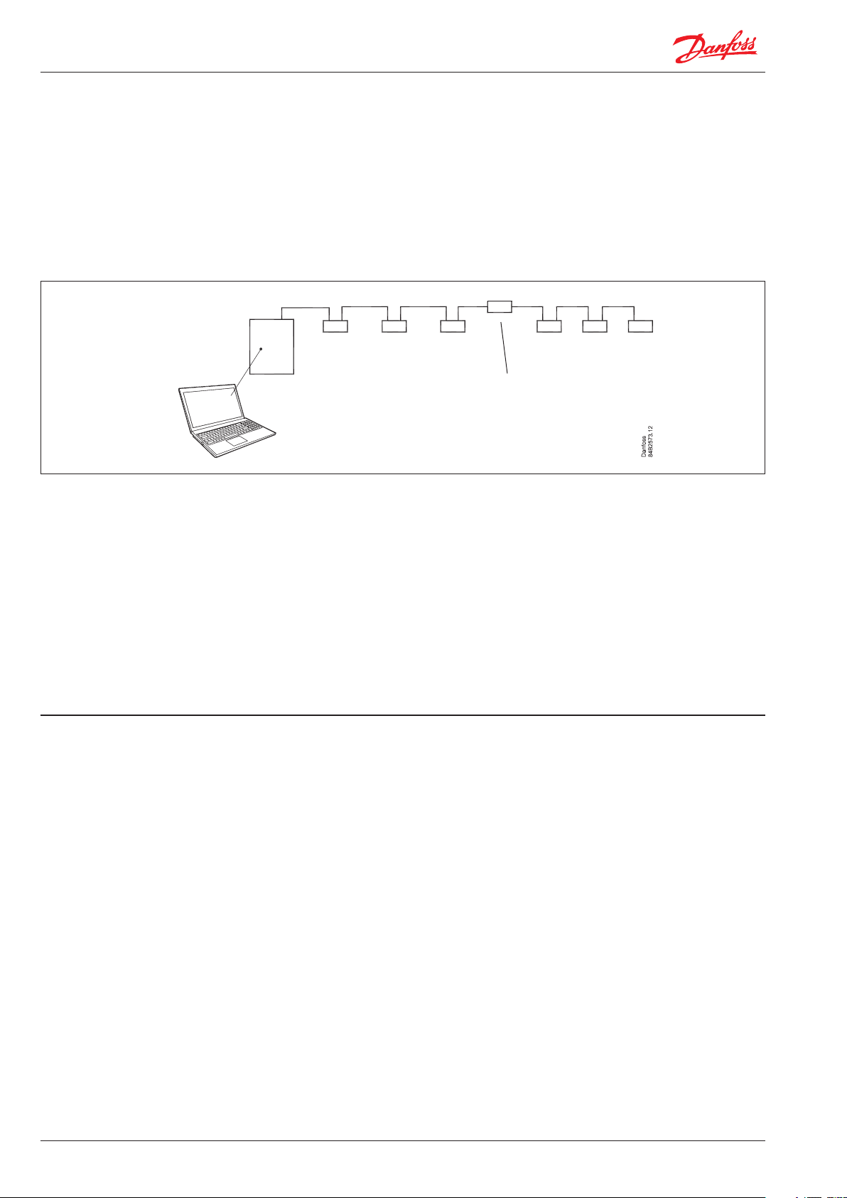
Data communication
System unit
System operation
The guide describes:
- The various forms of communication
- Cable to be used
- Length of cable
- Termination of cable
- When to install a repeater
and
- How do the individual controllers become visible on the network
- What happens if a controller has to be replaced
- What happens if the gateway has to be replaced
The recommendations mentioned in this document are intended
as instructions for the market’s refrigeration engineers and
electricians who install Danfoss refrigeration controls.
Controllers
Repeater
ADAP-KOOL® only
The above communication systems are used for internal communication between ADAP-KOOL® refrigeration control systems.
The devices are not designed to communicate with equipment
manufactured by other manufacturers.
IP network
In the case of controllers and system units that can be connected
to an IP network, installation should be carried out on the basis of
the requirements that apply to an IP network, i.e. cables must be at
least category 5.
Contents
Introduction .................................................................................2
A little about controllers and system units ...............................3
Communication survey ............................................................................... 3
System units .................................................................................................... 4
Addressing of controllers in the network ............................................. 6
Replacement of controllers in the network ......................................... 6
Replacement of system units in the network ..................................... 6
Requirements to installation ......................................................7
Important ......................................................................................................... 7
Lon RS 485 - bus ............................................................................................. 8
MOD - bus ...................................................................................................... 10
Lon TP 78 - bus .............................................................................................12
DANBUSS ........................................................................................................14
Combinations of net ..................................................................16
Bridge .............................................................................................................. 16
Repeater .........................................................................................................17
2 Design guide RC8AC902 © Danfoss 2017-06 Data communication
Page 3
A little about controllers and system units
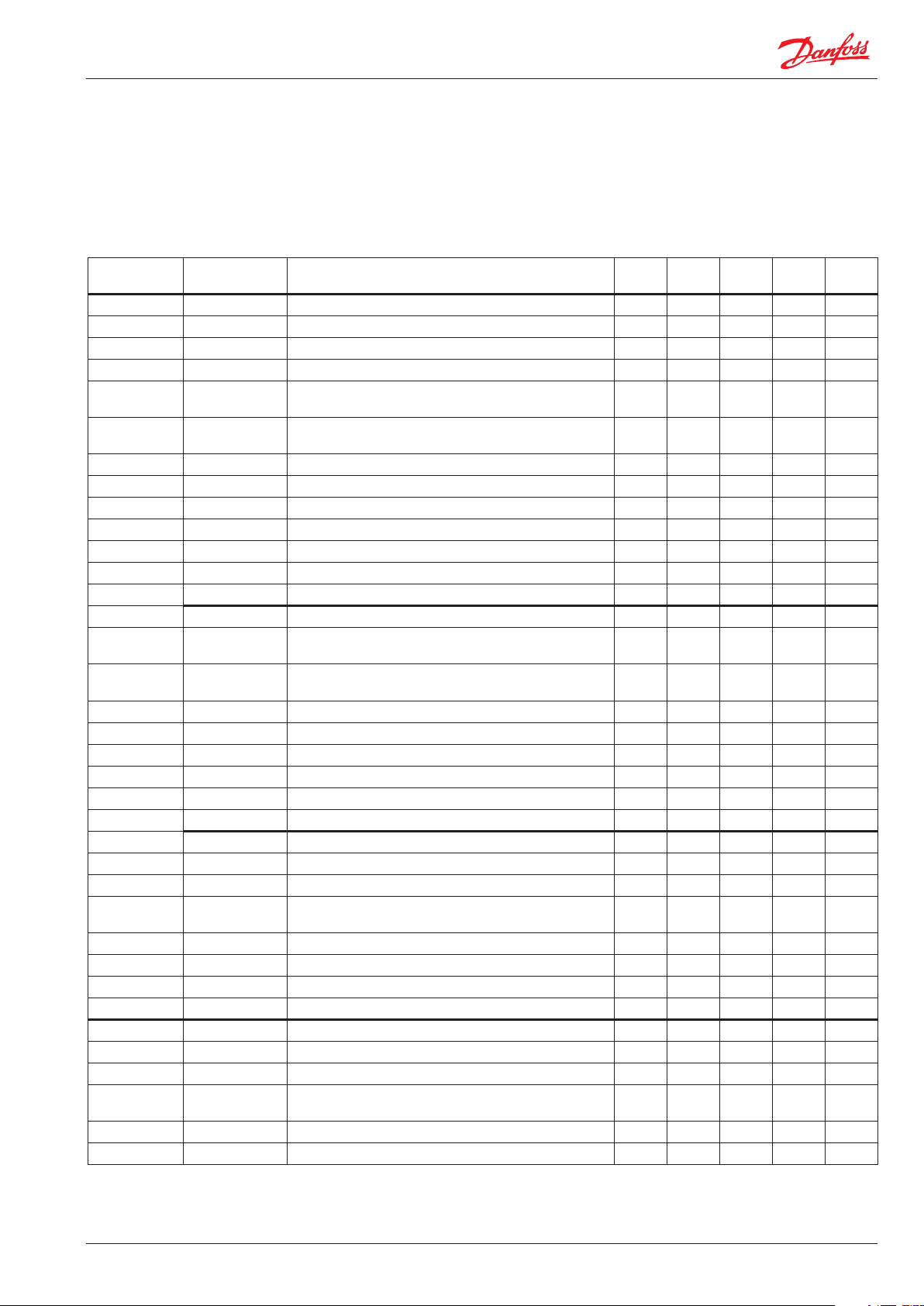
Communication survey
The table below shows which controllers can communicate with
which system units and with what form of data communication.
The summary is valid as of ultimo 2015, but the ADAP-KOOL®
Refrigeration Control System is continually being extended.
System
operation
AK-ST 500
AK-EM 100
AK-EM 800
1)
AKM
System unit Controller serie / type Lon
3)
AK-SM 800
2)
series
AK - controllers with extension modules
AK-CC, AK-PC, AK-LM, AK-CH
EKC 3xx x
EKC 202, AK-CC 210 x x
EKC 302, AK-CC 250, 350, AK-PC, AK-CT x
AK-CC 450, 550 (x) x (x)
AK-PI 200 x x
AK-CM (communication module) + AK-XM x x
DGS, SLV, Wattnote, Power meter, light control (3. party) x
RS485
Mod-
bus
Lon
TP 78
DANBUSS
x x x
x
IP
AK-SM 350
AK-SM 720
AK - controllers with extension modules
AK-CC, AK-PC, AK-LM, AK-CH
x x x
x
EKC 3xx x
EKC 202, AK-CC 210 x x
EKC 302, AK-CC 250, 350, AK-PC, AK-CT x
AK-CC 450, 550 (x) x (x)
AK-PI 200 x x
DGS, SLV x
AK-SC 255, 355 x
2)
x x
2)
AK-CM (communication module) + AK-XM x x
AK - controllers with extension modules
AK-CC, AK-PC, AK-LM, AK-CH
x
AK-CC 750 (TP 78 version) x
EKC 302, AK-CC 250, 350, 450, 550, AK-CT x
EKC 202, 4xx, 5xx, AK-CC, AK-PC x
AKM
EM 100 AKA 245 x x
AKA, AKC, AKL x
AK - controllers with extension modules
AK-CC, AK-PC, AK-LM, AK-CH
x
EKC 202, 302, 3xx, 4xx, 5xx, AK-CC 210 x
AK-CC 450, 550 x x
1) AKM can receive alarms and logs from an AK-SM 720 and AK-SM 350. The connection is made via an analogue modem, a GPS modem or an IP network.
2) Can be delivered in two versions:
- Standard Lon-RS485
- Retro-fit Lon TP 78.
3) Together with AK-SM 350 and AK-SM 720 only.
x
Data communication Design guide RC8AC902 © Danfoss 2017-06 3
Page 4
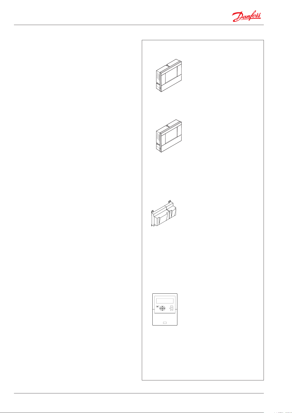
System units
A brief summary is presented here of the communication options
for the various system devices:
AK-SM 820
Up to 32 controllers can be connected, which can communicate
on:
- Lon
- Modbus
- External I/O modules via AK-CM 101C
- Ethernet communication for other AK-SM or AK-SC devices
- AK-PI 200 protocol interface with DANBUSS communication
AK-SM 850, AK-SM 880
Up to 120 controllers can be connected, which can communicate
on:
- Lon
- Modbus
- External I/O modules via AK-CM 101C
- Ethernet communication for other AK-SM or AK-SC devices
- AK-PI 200 protocol interface with DANBUSS communication
AK-SM 880 it can be delivered in a version, which can communicate in 4 x TP 78 or AK-CM 101A.
AK-SM 720
There are three forms of data communication:
- A Lon RS485 bus, to which up to 199 devices can be connected.
- A Modbus, to which up to 120 devices can be connected.
- Ethernet communication for other AK-SM devices, to which up to
199 addresses can be connected.
The system device can communicate with:
- AK-CC, AK-PC controllers
- EKC with either Lon RS485 or Modbus communication
- AK-PI 200 protocol interface with DANBUSS communication
- AK-PI 300 protocol interface for Daikin devices
- Other AK-SM 720 devices
- AKM and AK-EM 800 via agent.
Lon RS485
Modbus
IP network
Lon RS485
Modbus
IP network
Lon RS485 (max. 199 devices)
Modbus (max. 120 devices)
Total on bus: Lon RS 485 + Modbus: max. 199 devices
IP network (max. 199 addresses)
Total AK-SM 720 + AK-PI 200 + IP + bus: max. 200
devices.
A repeater must be added if there are more than 120
devices on the Lon RS485 communication.
Total up to 32 devices
Total up to 120 devices
AK-SM 350
This device can record up to 65 (99) readings. A reading could for
example be a directly mounted temperature sensor or an external
device with a temperature sensor, where the readings is loaded via
data communication.
There are four forms of data communication:
- A Lon RS485
- A Modbus
- RS485 TP (Third Party) To which gas detectors, type GD, can be
Lon RS485
Modbus
RS 485 TP
Total up to 65 (99) devices
connected
- Ethernet communication for other AK-SM 720 or AK-SC devices.
AK-SM 350 can communicate with:
IP network
- EKC with either Lon RS485 or Modbus communication
- AK-CC, AK-PC controllers
- Gas detectors type GD
- AK-PI 200 protocol interface with DANBUSS communication
- Ethernet communication for other AK-SM or AK-SC devices.
4 Design guide RC8AC902 © Danfoss 2017-06 Data communication
Page 5
AK-SC 255 / AK-SC 355
AK-SC 255 and 355 are available in 2 versions:
- Modbus + Lon TP 78 communication
- Modbus + Lon RS485 communication
- Ethernet communication for other AK-SC or AK-SM devices.
The system device can communicate with:
- External I/O modules via AK-CM 101C or 101A (depending on
model)
- All controllers where the communication is supported by:
Modbus, Lon, TP78).
Gateway type AKA 245
This system device is equipped with DANBUSS data communication and Lon RS485 data communication. It can control the
communication of up to 120 controllers. The controllers can be
distributed between Lon and DANBUSS by setting a continuous
Lon address range of up to 119 addresses.
The system device can create communication for type AKM system software.
The system device can communicate with:
- AKC controllers
- EKC controllers with a Lon RS 485 communication
- AK-CC, AK-PC controllers
- AK-EM 800 via Agent
Modbus
Lon RS485 / TP 78
IP network
DANBUSS
Lon RS485
Total up to 120 devices
Data communication Design guide RC8AC902 © Danfoss 2017-06 5
Page 6

Addressing of controllers in the network
1. Connect voltage
2. Set the address in the respective controllers
If you should inadvertently give two or more controllers the
same address, only the first controller will be visible from the
system device.
3. The system device must know the controllers.
The following will occur depending on the communication type:
Lon RS485
Or better: The system device can scan the network and find all
connected controllers. This scan function must be started manually in the system device.
Modbus, TP78
Replacement of controllers in the network
Settings
The system operation includes functions to copy a controller’s
settings. This function can be used where a controller is to be
replaced with the same software version. After swapping, the settings are copied back onto the controller.
Address
Remember to reset the address of the controller with the same
address and get the controller to notify the system device again.
(You should also do this yourself if you are retaining the existing
LON module).
Here, the controller can send a service PIN to the system device.
Here, the system device must scan the network.
The service PIN function on each controller cannot send the address to the system device.
DANBUSS
On DANBUSS, the addresses must be set before the power is
switched on.
The system device will find the controllers on the network itself.
Modbus, TP78
The system device will scan the network and find the controllers
that have been replaced. This scan function must be started manually in the system device.
Lon RS485
• AK-SC 255, 355, SM 850
The system device will scan the network and find the controllers that have been replaced. This scan function must be started
manually in the system device.
• AK-SM 350, 720, AKA 245
Here, the controller will send a service PIN to the system device.
Replacement of system units in the network
If you replace the system device, all settings and data can be
retrieved and reloaded with a backup function. See user Guide for
the respective system device, so you can see how the setup and
the collected data is retained.
• Terminate data communication inputs as previously
• Set the system device address
• Load the controller addresses up to the system device.
AK-SM 820, 850, 880
Set the address to the same value as on the previous system
device. Then start the Rescan function.
AK-SM 350
No address needs to be set on AK-SM 350.
Start the scan function to find all connected controllers.
DANBUSS
On DANBUSS the system device will find the controllers on the
network itself.
AK-SM 720
Set the address to the same value as on the previous system
device. The scan function can then be started to find all connected
controllers.
AK-SC 255, 355
Set the address to the same value as on the previous system device. Then start the Rescan function.
Gateway type AKA 245
Set the system address using the AKA 21 operating device.
On the DANBUSS communication, the Gateway will find the controllers itself.
On Lon RS485 the scan function can be activated from the AKA 21
operating module. This function is called “Press Enter to scan LON
bus”.
NB! When the scan function is used, all alarm priorities in all
connected EKC controllers will be deleted and returned to their
factory settings.
6 Design guide RC8AC902 © Danfoss 2017-06 Data communication
Page 7

Requirement to installation
Cable type
Cables twisted in pairs must be used, and they may be provided
with a screen.
Some types of communication require a cable with a screen to be
used.
• Examples
For Lon RS485, Modbus, RS485 Third party - General 'EIA 485' recommendation:
- Belden 9841, 24 AWG, 1 pair with screen
- Belden 3107A, 22 AWG, 2 pairs with screen
- Smartwire 043006AL, 22 AWG, 1 pair with screen
- Alpha wire 6453, 22 AWG, 1 pair with screen
- Carol C4841A, 24 AWG, 1 pair with screen
- Dätwyler Uninet 3002 4P 4 pairs with screen(CAT5 cable)
For Lon TP78 communication - Level 4 cable general recommendation:
- Belden 7703NH, 22 AWG, 1 pair with screen
- Belden 7704NH, 22 AWG, 2 pair with screen
- Smartwire 106500, 22 AWG, 1 pair with screen
Important!
Our experience indicates that problems can occur with communication due to the following weaknesses:
Long wire ends
Do not strip more of the cable insulation than strictly neces sary.
Max. 3-4 cm. Continue the twisting of the cables right up to the
terminals.
Wires with larger cross-section than AWG 22 is not recommended.
( Eg. AWG 20 and 19).
Conductors
The wires in the cable that is connected to the controller must
be correct. Although there are four wires in the cable inside the
screen, you cannot simply choose colours freely. The wires are
twisted in pairs, i.e. 2 and 2, and you must use a pair that is twisted
around each other.
If there are several “vacant” wires in the cable, they must be used
for nothing else than data communication.
Cable length
A cable length must not exceed 1200 m.
A repeater must be used for longer lengths than 1200 m.
See the additional requirements for the respective communication forms.
Cable tray
Max. 3-4 cm
Min.10-15 cm
Stubs
Avoid stubs on the cable. Feed the cable right to the end and then
back again.
Noise sources
Keep the cable away from electrical noise sources and power
cables (relays, contactors and especially electronic ballast for strip
lights are strong noise sources). A distance of at least 10-15 cm will
be sufficient.
Cable length extremities
Each section of data communication must be terminated correctly. See the relevant communication form on the following pages.
Termination with a resistance of 120 Ω. Either directly on the
terminals or with a switch.
Screen
See the respective communication forms.
When the cable is ducted with
other cables, there is a strong
risk that electrical noise will be
transferred. Keep away from live
cables.
When the cable is ducted in a
cable tray, the cable must be fed
out and right up to the controller. The fast solution where only
wires are fed out will cause
problems.
Cabinet mounting
When controllers are installed in a cabinet, internal cable ducting
must also comply with the relevant requirements. Use this cable
ducting when one or more controllers are installed in a cabinet.
(The short connections between controllers must also be of the
correct cable types.)
Min.
10-15 cm
Keep a distance to relays, their cables and other things
emitting electric noises.
When controllers are fitted in a cabinet door, the cables are usually
kept together in bundles of cables. Here the bundle with data
communication, display and digital input signals must be kept
separate from other cables that emit noise.
Data communication Design guide RC8AC902 © Danfoss 2017-06 7
Page 8

Lon RS 485 - bus
See also page 7.
This data communication is primarily used in controllers in the
series:
• EKC..
• AK-CC, AK-PC...
System unit
Wiring
Number of controllers
The total number of controllers on an LON RS485 connection is
determined by the system device and can vary between 32 and
200. See the summary of system options on page 4.
The system devices must be:
• System manager from the serie AK-SM
• System manager from the serie AK-SC
• Gateway type AKA 245
The cable is connected from controller to controller, and no
branches are allowed on the cable.
The System Manager can be inserted in middle of network.
(However, not AK-SC 255 and 355, which have a fixed termination
= ON.) See page 9 for drawing.
If the cable length exceeds 1200 m a repeater must be inserted
If the data communication cable runs through an electrically
noisy environment which impairs the data signal, one or more
repeaters must be added to stabilise the signal.
The repeater is placed so that the length of the cable is evenly
distributed.
See page 17 for more information on repeaters.
Conductors
8 Design guide RC8AC902 © Danfoss 2017-06 Data communication
The two wires are looped from device to device. There are no
polarisation requirements.
(On some controllers, the clamps are designated A and B. On
others there is no designation. Otherwise the connections are
identical.)
If a screen is used, ensure screen is connected to system device
and any repeaters.
A screen must always be looped from device to device.
The screen must not be connected to anything else.
(The screen is earthed inside the system device and must not be
earthed in any other way.)
Page 9

Cable sections/termination
System unit
Termination = Off
When all cables have been mounted on the different units, the
cable must be terminated.
A section must be terminated at both ends. The section must be
terminated using either an external resistor or a contact. Please
see the relevant device.
A repeater will normally terminate two cable sections.
The termination should be made with a 120-ohm resistor. (The
resistor can be in the range 100 to 130 ohms.)
System unit
Termination = On
Repeater
A repeater will always terminate two cable sections.
Data communication Design guide RC8AC902 © Danfoss 2017-06 9
Page 10

MOD - bus
See also page 7.
This data communication can be used in the serie:
• EKC..
• AK-CC
• AK-CT
System unit
Wiring
The system device must be:
• System manager type AK-SM
• System manager type AK-SC
The cable must be with screen.
The cable is connected from controller to controller, and no
branches are allowed on the cable.
The System Manager can be inserted in middle of network.
(However, not AK-SC 255 and 355, which have a fixed termination
= ON.) See page 11 for drawing.
If the cable length exceeds 1200 m a repeater must be inserted
If the data communication cable runs through an electrically
noisy environment which impairs the data signal, one or more
repeaters must be added to stabilise the signal.
The repeater is placed so that the length of the cable is evenly
distributed.
32
See page 17 for more information on repeaters.
Number of controllers
The total number of controllers on MOD bus connection can be
up to 120. See the summary of system options on page 4.
Conductors
The wires are looped from device to device.
A is connected to A
B is connected to B.
The screen must be connected to the system device, all controllers and any repeaters.
A screen must always be looped from device to device.
The screen must not be connected to anything else.
(The screen is earthed inside the system device and must not be
earthed in any other way.)
10 Design guide RC8AC902 © Danfoss 2017-06 Data communication
Page 11

Cable sections / termination
System unit
Termination = Off
System unit
Termination = On
When all cables have been mounted on the different devices, the
cable must be terminated.
A section must be terminated at both ends. The section must be
terminated using either an external resistor or a contact. Please
see the relevant device.
A repeater will always terminate two cable sections.
The termination should be made with a 120-ohm resistor. (The
resistor can be in the range 100 to 130 ohms.)
Repeater
Data communication Design guide RC8AC902 © Danfoss 2017-06 11
Page 12

Lon TP 78 - bus
System unit
Wiring
See also page 7.
This data communication is no longer recommended for new
installation, Danfoss can provide units for retro-fit:
• System controller type AK-SC 255, 355 and AK-SM 8xx
• AK-CM - communication modules
• AK-CC - Case control (TP 78 version)
Cables with screen must be used.
The cable is connected from controller to controller, and no
branches are allowed on the cable.
System Manager AK-SM 8xx can be inserted in middle of network.
(However, not AK-SC 255 and 355, which have a fixed termination
= ON.) See page 13 for drawing.
A cable section must not be longer than 1200m.
A repeater must be used for longer sections.
System unit
Number of controllers
The total number of controllers on a TP 78 connection is determined by the controlling unit and can be up to 120. See the summary of system options on page 4.
Conductors
The sum of all sections must not exceed 1200m.
A repeater must be used if the sum is greater.
If the data communication cable runs through an electrically
noisy environment which impairs the data signal, one or more
repeaters must be added to stabilise the signal.
The repeater is placed so that the length of the cable is evenly
distributed.
See page 17 for more information on repeaters.
The two wires are looped from device to device. There are no
polarisation requirements.
The screen must be connected to the system manager and any
repeaters.
A screen must always be looped from device to device.
The screen must not be connected to anything else.
(The screen is earthed inside the device and must not be earthed
in any other way.)
12 Design guide RC8AC902 © Danfoss 2017-06 Data communication
Page 13

Cable sections / termination
System unit
Termination = Off
When all cables have been mounted on the different devices, the
cable must be terminated.
A section must be terminated at the end of each sections.
Termination is performed with the resistors (terminations) supplied.
If one or more of the sections is not used, the termination on the
clamp row should be retained.
A repeater will always terminate two cable sections.
A section after a repeater must be terminated at both ends.
System unit.
Termination:
All = On
Data communication Design guide RC8AC902 © Danfoss 2017-06 13
Page 14

DANBUSS
System unit
Wiring
See also page 7.
This data communication is no longer recommended for new
installation, Danfoss can provide units for retro-fit:
• AK-CC.
The system device must be a gateway type:
• AKA 245 or
• Interface module AK-PI 200 + a AK-SM unit
Cable must be with screen.
The cable is connected from controller to controller, and no
branches are allowed on the cable.
If the cable length exceeds 1200 m a repeater must be inserted.
If the data communication cable runs through an electrically
noisy environment which impairs the data signal, one or more
repeaters must be added to stabilise the signal.
The repeater is placed so that the length of the cable is evenly
distributed.
Nubmer of controllers
The total number of controllers on an Danbuss connection is
determined by the controlling device and can vary between 60
and 120. See the summary of system options on page 4.
Conductors
See page 17 for more information on repeaters.
The wires are looped from device to device. L (K3) is connected to
L (K3) and H (K4) to H (K4).
The screen must be connected to screen (k1) on all controllers and
any repeaters. The screen must not be connected to anything else.
(The screen is earthed inside the system device and must not be
earthed in any other way.)
14 Design guide RC8AC902 © Danfoss 2017-06 Data communication
Page 15

Cable sections / termination
System unit.
Termination = On
System unit.
Termination = On
When all cables have been mounted on the different units, the
cable must be terminated.
The termination is made using changeover switches and bow
contacts.
A section must be terminated at both ends. The section must be
terminated using either an external resistor or a contact. Please
see the relevant device.
A repeater will always terminate two cable sections.
The termination should be made with a 120-ohm resistor. (The
resistor can be in the range 100 to 130 ohms.)
Data communication Design guide RC8AC902 © Danfoss 2017-06 15
Page 16

Combinations of net
Bridge
A bridge is a signal transition from one type of data communication to a different type.
A bridge has no address.
Multiple bridges and bridge types can be mixed on a common
loop.
Lon FTT 10 to Lon RS 485 and reverse
A bridge type TP78-05 can be used.
Code no. = 084B22 55.
Lon TP 78 to Lon RS 485 and reverse
A bridge type TP78-04 can be used.
Code no. = 084B2254.
Lon TP 78 to Lon FTT10 and reverse
A bridge type TP78-02 can be used.
Code no. = 084B2252.
DANBUSS to AK-SM 720
Protocol interface AK-PI 200 can be used.
Literature no. = RS8EX.
16 Design guide RC8AC902 © Danfoss 2017-06 Data communication
Page 17

Repeater
A repeater is a device that refreshes the signal so that the signal
can be read further out on the communication line.
Location-recommended to be in middle of loop so distance is split
in half.
A repeater has no address.
Lon RS 485
A repeater from the company "Phoenix" can be used:
Danfoss code no = 084B2241 (type AKA 223)
On Lon RS485 the communication speed is set to 78.1 kbps on the
repeater.
MOD-bus
A repeater from the company "Phoenix" can be used:
Danfoss code no. = 084B2240 (type AKA 222).
On Modbus the communication speed is set to 38.4 kbps on the
repeater. (A cable section with SLV must be set to 19.2 kbps.)
Lon TP 78
A repeater type TP78-01 can be used.
DANBUSS
A repeater from the company "Phoenix" can be used:
Danfoss code no. = 084B2240 (type AKA 222).
On DANBUSS the communication speed is set to 4.8 kbps on the
repeater.
A on the repeater must be connected to DANBUSS-terminal L.
B on the repeater must be connected to DANBUSS-terminal H.
Data communication Design guide RC8AC902 © Danfoss 2017-06 17
Page 18

LonWorks® is a registered trademark, belonging ECHELON Corporation.
Danfoss can accept no responsibility for possible errors in catalogues, brochures and other printed material. Danfoss reserves the right to alter its products without notice. This also applies to products
already on order provided that such alternations can be made without subsequential changes being necessary in specifications already agreed.
All trademarks in this material are property of the respecitve companies. Danfoss and Danfoss logotype are trademarks of Danfoss A/S. All rights reserved.
18 Design guide RC8AC902 © Danfoss 2017-06 Data communication
ADAP-KOOL0174
 Loading...