

Page 1

Contents
Contents
ADAP-KOOL
®
Drive Operating Instructions
1 Introduction
1.1.2 Copyright, Limitation of Liability and Revision Rights 4
1.1.6 Type Code String 6
2 Safety
2.1.2 High Voltage Warning 7
2.1.5 Before Commencing Repair Work 8
2.1.6 Special Conditions 9
2.1.7 Safe Stop of the Frequency Converter 9
2.1.8 IT Mains 11
3 Application Guide
3.1.1 ADAP-KOOL® Drive Application Guide 12
3.1.2 Application Descriptions
4 Mechanical Installation
4.1 Before starting
4.1.2 Mechanical Dimensions 20
3
7
12
17
19
19
4.2 How to Install
5 Electrical Installation
5.1 How to Connect
5.1.2 Electrical Installation and Control Cables 26
5.1.5 Mains Wiring Overview 30
5.1.11 Motor Wiring Overview 36
5.1.19 How to Test Motor and Direction of Rotation 41
6 How to Operate the Frequency Converter
6.1.2 How to Operate the Graphical LCP (GLCP) 45
6.1.6 Tips and Tricks 52
7 How to Programme the Frequency Converter
7.1 How to Programme
7.2 Parameter list
7.2.1 0-** Operation and Display 81
7.2.2 1-** Load / Motor 83
23
25
25
45
54
54
80
7.2.3 2-** Brakes 84
7.2.4 3-** Reference / Ramps 85
7.2.5 4-** Limits / Warnings 86
7.2.6 5-** Digital In / Out 87
7.2.7 6-** Analog In / Out 89
MG.11.L4.02 - ADAP-KOOL® Drive 1
Page 2

Contents
ADAP-KOOL
7.2.8 8-** Communication and Options 91
7.2.9 11-** ADAP-KOOL LON 92
7.2.10 13-** Smart Logic Controller 93
7.2.11 14-** Special Functions 94
7.2.12 15-** FC Information 95
7.2.13 16-** Data Readouts 97
7.2.14 18-** Info & Readouts 99
7.2.15 20-** FC Closed Loop 100
7.2.16 21-** Ext. Closed Loop 101
7.2.17 22-** Application Functions 103
7.2.18 23-** Time Based Funtions 105
7.2.19 25-** Pack Controller 106
7.2.20 26-** Analog I / O Option MCB 109 107
7.2.21 28-** Compressor Functions 108
®
Drive Operating Instructions
8 Troubleshooting
8.1.1 Warning/Alarm list 112
9 Specifications
9.1 General Specifications
9.2 Special Conditions
Index
109
116
116
124
128
2 MG.11.L4.02 - ADAP-KOOL® Drive
Page 3

Introduction
ADAP-KOOL
®
Drive Operating Instructions
1Introduction
1.1 Introduction
The AKD 102 ADAP-KOOL Drive from Danfoss Food Retail has been designed with our refrigeration customers clearly in
mind. The drive is designed to make commissioning and installation a simple and easy task. The built in “wizard” set up
menu guides the installer through the set up of the drive in a clear and structured manner, and has been constructed with
reference to the industries refrigeration engineers, to ensure that the text and language used makes complete sense to the
installer.
The AKD 102 drive comes with a common user interface which covers all power ratings between 1.1- 250 kW. Thus ensuring
that once you have learnt how to commission one drive you understand how to commission them all. Included on this local
control panel is an “info” button which is essentially a built in drive instruction manual which help the user to both gain
information and also suggests other parameters which may need to be changed. The AKD 102 also features a built in “pack
controller” controlled via the drives own standard software. This allows the drive to control the lead compressor via variable
speed and the bringing on line of another 2 compressors in fixed speed mode. This leads to extremely efficient pack design
which also adds the energy efficiency of variable speed control. Using the drive in this way eliminates the need for an
external pack controller thus giving financial savings to the customer.
1
1
The drive can be supplied in either of two protection classes IP21(IP20 up to 7,5kW) or IP55 (IP66 on request); this insures
that our customers benefit from having the most robust of designs supplied directly from the factory, without the need for
additional cabinets in which to house the drive. The AKD also benefits from the inclusion of having built in RFI filters as
standard which means that the problems associated with radio interference and long cable runs are no problem for our
customers.
The modular construction of the AKD means that you only have to pay for what you need. Each AKD is manufactured only
when we receive a customer order and so is built exactly to customer specification with any chosen options added at this
stage. But by using this manufacturing and design philosophy it means that should options such as ADAP-KOOL Lon be
required at some future date they are a simple retrofit inside of the drive which can be done by anyone with extreme ease.
Warranty: Each AKD comes with 18 months warranty from date of manufacture or 12 months from date of documented
installation, whichever comes first thus ensuring that our Food Retail customers have complete peace of mind when
choosing AKD as their drive of choice.
1.1.1
Software Version and Approvals: ADAP-KOOL
ADAP-KOOL® Drive
Operating Instructions
Software version: 2.xx
®
Drive
This Operating Instructions can be used for all ADAP-KOOL® Drive frequency converters with software version 2.xx.
The software version number can be seen from parameter 15-43.
MG.11.L4.02 - ADAP-KOOL® Drive 3
Page 4

Introduction
ADAP-KOOL
®
Drive Operating Instructions
1
1.1.2 Copyright, Limitation of Liability and Revision Rights
This publication contains information proprietary to Danfoss. By accepting and using this manual the user agrees that the
information contained herein will be used solely for operating equipment from Danfoss or equipment from other vendors
provided that such equipment is intended for communication with Danfoss equipment over a serial communication link.
This publication is protected under the Copyright laws of Denmark and most other countries.
Danfoss does not warrant that a software program produced according to the guidelines provided in this manual will
function properly in every physical, hardware or software environment.
Although Danfoss has tested and reviewed the documentation within this manual, Danfoss makes no warranty or representation, neither expressed nor implied, with respect to this documentation, including its quality, performance, or fitness for a
particular purpose.
In no event shall Danfoss be liable for direct, indirect, special, incidental, or consequential damages arising out of the use, or
the inability to use information contained in this manual, even if advised of the possibility of such damages. In particular,
Danfoss is not responsible for any costs, including but not limited to those incurred as a result of lost profits or revenue,
loss or damage of equipment, loss of computer programs, loss of data, the costs to substitute these, or any claims by third
parties.
Danfoss reserves the right to revise this publication at any time and to make changes to its contents without prior notice or
any obligation to notify former or present users of such revisions or changes.
1.1.3 Available Literature
- Operating Instructions MG.11.Lx.yy provide the neccessary information for getting the drive up and running.
- Design Guide MG.11.Mx.yy entails all technical information about the drive and customer design and applications.
- Programming Guide MG.11.Nx.yy provides information on how to programme and includes complete parameter
descriptions.
- Operating Instructions AKD102 High Power, MG.11.Ox.yy
- Operating InstructionsAKD LonWorks, MG.11.Px.yy
x = Revision number
yy = Language code
Danfoss Drives technical literature is also available online at www.danfoss.com/BusinessAreas/DrivesSolutions/Documentations/
Technical+Documentation.htm.
4 MG.11.L4.02 - ADAP-KOOL® Drive
Page 5
Introduction
ADAP-KOOL
1.1.4 Abbreviations and Standards
®
Drive Operating Instructions
1
1
Abbreviations: Terms: SI-units: I-P units:
a Acceleration
AWG American wire gauge
Auto Tune Automatic Motor Tuning
°C
I Current A Amp
I
LIM
Joule Energy J = Nm ft-lb, Btu
°F
FC Frequency Converter
f Frequency Hz Hz
kHz Kilohertz kHz kHz
LCP Local Control Panel
mA Milliampere
ms Millisecond
min Minute
MCT Motion Control Tool
M-TYPE Motor Type Dependent
Nm Newton Metres in-lbs
I
M,N
f
M,N
P
M,N
U
M,N
par. Parameter
PELV Protective Extra Low Voltage
Watt Power W Btu/hr, hp
Pascal Pressure Pa = N/m psi, psf, ft of water
I
INV
RPM Revolutions Per Minute
SR Size Related
TTemperature CF
t Time s s,hr
T
LIM
U Voltage V V
Celsius
Current limit
Fahrenheit
Nominal motor current
Nominal motor frequency
Nominal motor power
Nominal motor voltage
Rated Inverter Output Current
Torque limit
m/s
2
ft/s
2
Table 1.1 Abbreviation and standards table.
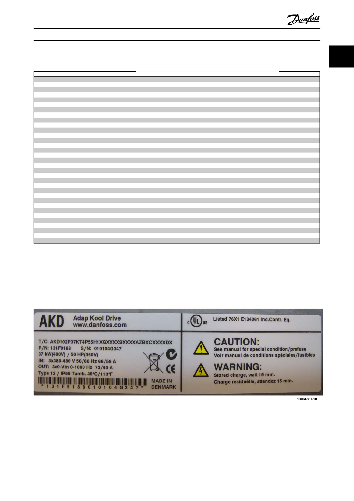
1.1.5 Frequency Converter Identification
Below is an example of an identification label. This label is situated on the frequency converter and shows the type and
options fitted to the unit. See table 2.1 for details of how to read theType code string (T/C).
Illustration 1.1 This example shows an identification label.
NOTE
Please have T/C (type code) number and serial number ready before contacting Danfoss.
MG.11.L4.02 - ADAP-KOOL® Drive 5
Page 6
Introduction
ADAP-KOOL
®
Drive Operating Instructions
1
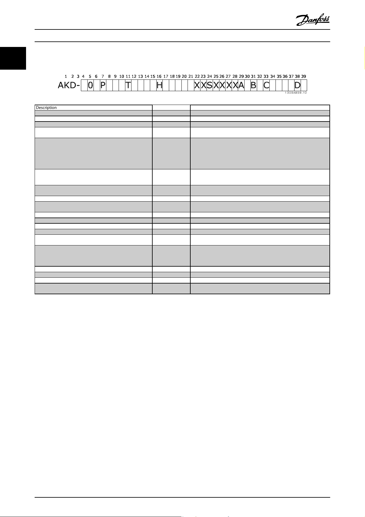
1.1.6 Type Code String
Description Pos Possible choice
Product group & VLT Series 1-6 AKD102
Power rating 8-10 1.1 - 250 kW (P1K1 - P250)
Number of phases 11 Three phases (T)
Mains voltage 11-12
Enclosure 13-15
RFI filter 16-17
Display 19
Coating PCB 20 C: Coated PCB
Mains option 21
Adaptation 22 Reserved
Adaptation 23 Reserved
Software release 24-27 Actual software
Software language 28
A options 29-30
B options 31-32
C0 options MCO 33-34 CX: No options
C1 options 35 X: No options
C option software 36-37 XX: Standard software
D options 38-39
T 2: 200-240 VAC
T 4: 380-480 VAC
E20: IP20
E21: IP 21/NEMA Type 1
E55: IP 55/NEMA Type 12
E66: IP66
P21: IP21/NEMA Type 1 w/backplate
P55: IP55/NEMA Type 12 w/backplate
H1: RFI filter class A1/B
H2: RFI filter class A2
H4: RFI filter class A2/A1
G: Graphical Local Control Panel (GLCP)
X: No Local Control Panel
X: No Mains disconnect switch
1: With Mains disconnect switch (IP55 only)
AX: No options
AZ: MCA 107AKD LonWorks
BX: No option
BK: MCB 101 General purpose I/O option
BP: MCB 105 Relay option
BO:MCB 109 Analog I/O option
DX: No option
D0: DC back-up MCB107
Table 1.2 Type code description.
The various options are described further in the ADAP-KOOL® Drive AKD102 Design Guide, MG.11.Mx.yy.
6 MG.11.L4.02 - ADAP-KOOL® Drive
Page 7
Safety
2
2Safety
ADAP-KOOL
®
Drive Operating Instructions
2.1.1 Symbols
Symbols used in this manual:
NOTE
Indicates something to be noted by the reader.
CAUTION
Indicates a general warning.
WARNING
Indicates a high-voltage warning.
✮
Indicates default setting
2.1.2 High Voltage Warning
WARNING
The voltage of the frequency converter and the MCO 101 option card is dangerous whenever it is connected to mains.
Incorrect installation of the motor or frequency converter may causedeath, serious injury or damage to the equipment.
Consequently, it is essential to comply with the instructions in this manual as well as local and national rules and safety
regulations.
2
2.1.3 Safety Note
WARNING
The voltage of the frequency converter is dangerous whenever connected to mains. Incorrect installation of the motor,
frequency converter or fieldbus may cause death, serious personal injury or damage to the equipment. Consequently, the
instructions in this manual, as well as national and local rules and safety regulations, must be complied with.
Safety Regulations
1. The frequency converter must be disconnected from mains if repair work is to be carried out. Check that the mains
supply has been disconnected and that the necessary time has passed before removing motor and mains plugs.
2. The [STOP/RESET] key on the LCP of the frequency converter does not disconnect the equipment from mains and
is thus not to be used as a safety switch.
3. Correct protective earthing of the equipment must be established, the user must be protected against supply
voltage, and the motor must be protected against overload in accordance with applicable national and local
regulations.
4. The earth leakage currents are higher than 3.5 mA.
5. Protection against motor overload is set by 1-90 Motor Thermal Protection. If this function is desired, set 1-90 Motor
Thermal Protection to data value [ETR trip] (default value) or data value [ETR warning]. Note: The function is
initialized at 1.16 x rated motor current and rated motor frequency. For the North American market: The ETR
functions provide class 20 motor overload protection in accordance with NEC.
6. Do not remove the plugs for the motor and mains supply while the frequency converter is connected to mains.
Check that the mains supply has been disconnected and that the necessary time has passed before removing
motor and mains plugs.
MG.11.L4.02 - ADAP-KOOL® Drive 7
Page 8
2
Safety
7. Please note that the frequency converter has more voltage inputs than L1, L2 and L3, when load sharing (linking
of DC intermediate circuit) and external 24 V DC have been installed. Check that all voltage inputs have been
disconnected and that the necessary time has passed before commencing repair work.
Installation at high altitudes
ADAP-KOOL
®
Drive Operating Instructions
WARNING
Installation at high altitude:
380 - 500 V, enclosure A, B and C: At altitudes above 2 km, please contact Danfoss regarding PELV.
380 - 500 V, enclosure D, E and F: At altitudes above 3 km, please contact Danfoss regarding PELV.
WARNING
Warning against Unintended Start
1. The motor can be brought to a stop by means of digital commands, bus commands, references or a local stop,
while the frequency converter is connected to mains. If personal safety considerations make it necessary to ensure
that no unintended start occurs, these stop functions are not sufficient.
2. While parameters are being changed, the motor may start. Consequently, the stop key [STOP/RESET] must always
be activated; following which data can be modified.
3. A motor that has been stopped may start if faults occur in the electronics of the frequency converter, or if a
temporary overload or a fault in the supply mains or the motor connection ceases.
WARNING
Touching the electrical parts may be fatal - even after the equipment has been disconnected from mains.
Also make sure that other voltage inputs have been disconnected, such as external 24 V DC, load sharing (linkage of DC
intermediate circuit), as well as the motor connection for kinetic back up. Refer to the Operating Instructions for further
safety guidelines.
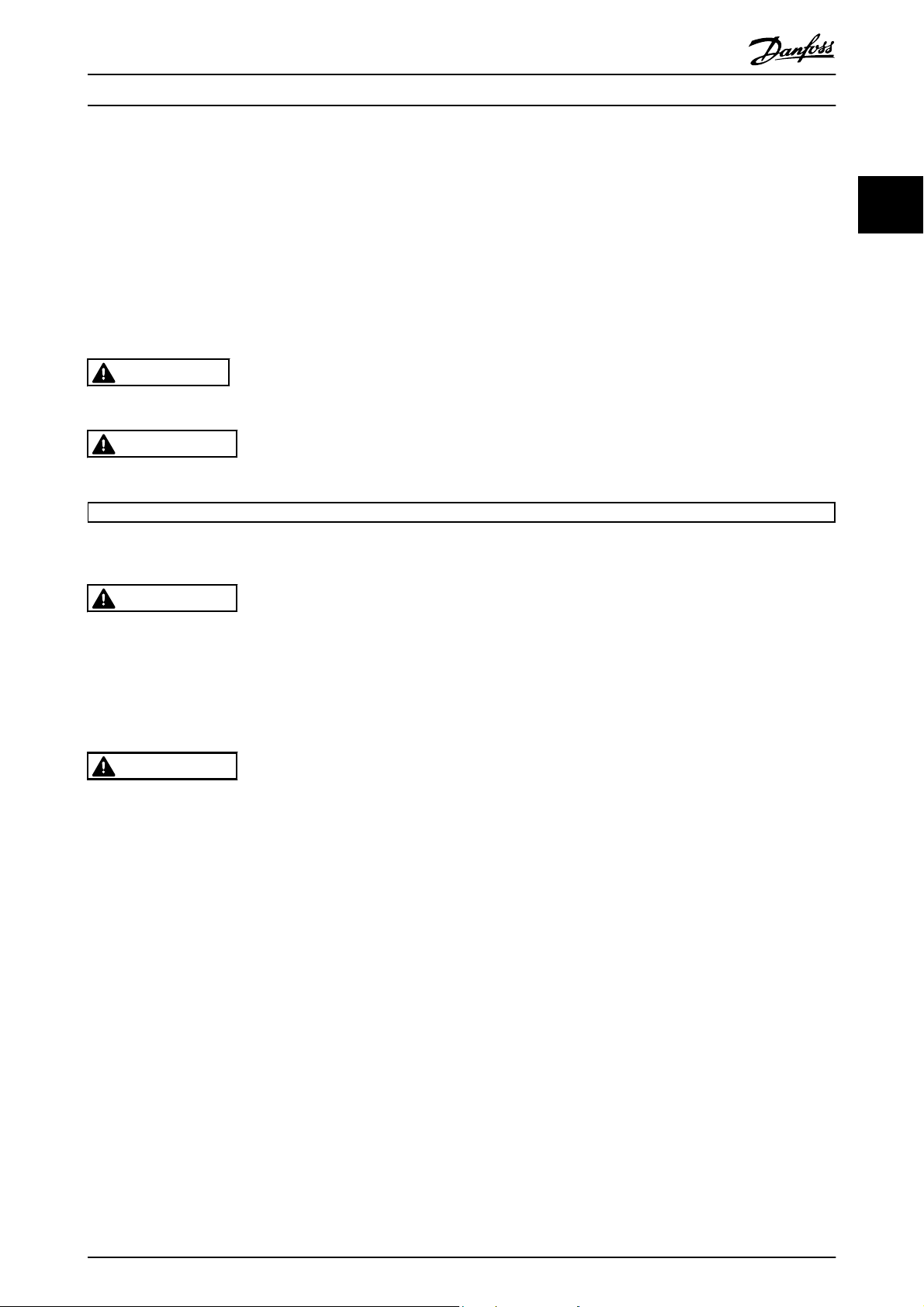
2.1.4 Caution
Caution
The frequency converter DC link capacitors remain charged after power has been disconnected. To avoid an electrical shock hazard, disconnect the
frequency converter from the mains before carrying out maintenance. Wait at least as follows before doing service on the frequency converter:
Voltage
200 - 240 V 1.1 - 3.7 kW 5.5 - 45 kW
380 - 480 V 1.1 - 7.5 kW 11 - 90 kW
Be aware that there may be high voltage on the DC link even when the LEDs are turned off.
4 min. 15 min.
2.1.5 Before Commencing Repair Work
Minimum Waiting Time
1. Disconnect the frequency converter from mains
2. Disconnect DC bus terminals 88 and 89
3. Wait at least the time mentioned in section General Warning above
4. Remove motor cable
8 MG.11.L4.02 - ADAP-KOOL® Drive
Page 9

Safety
2
2.1.6 Special Conditions
ADAP-KOOL
®
Drive Operating Instructions
Electrical ratings:
The rating indicated on the nameplate (Illustration 2.1) of the frequency converter is based on a typical 3-phase mains
power supply, within the specified voltage, current and temperature range, which is expected to be used in most
applications.
The frequency converters also support other special applications, which affect the electrical ratings of the frequency
converter.
Special conditions which affect the electrical ratings might be:
□ Single phase applications
□ High temperature applications which require de-rating of the electrical ratings
□ Marine applications with more severe environmental conditions.
Other applications might also affect the electrical ratings.
Consult the relevant clauses in these instructions and in the AKD102 Design Guide, MG.11.Mx.yy for information about the
electrical ratings.
Installation requirements:
The overall electrical safety of the frequency converter requires special installation considerations regarding:
□ Fuses and circuit breakers for over-current and short-circuit protection
□ Selection of power cables (mains, motor, brake, loadsharing and relay)
□ Grid configuration (IT,TN, grounded leg, etc.)
□ Safety of low-voltage ports (PELV conditions).
2
Consult the relevant clauses in these instructions and in the AKD102 Design Guide for information about the installation
requirements.
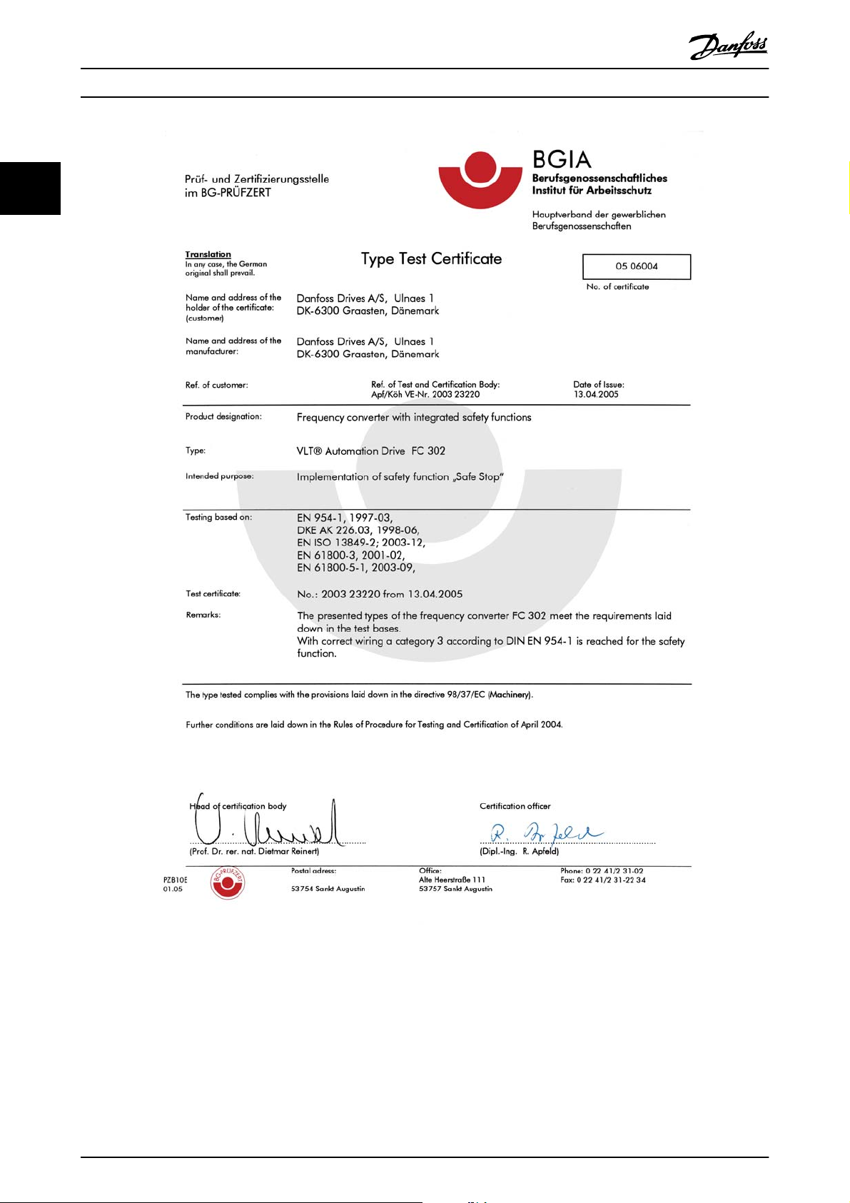
2.1.7 Safe Stop of the Frequency Converter
For versions fitted with a Safe Stop terminal 37 input, the frequency converter can perform the safety function Safe Torque
Off (As defined by draft CD IEC 61800-5-2) or Stop Category 0 (as defined in EN 60204-1).
It is designed and approved suitable for the requirements of Safety Category 3 in EN 954-1. This functionality is called Safe
Stop. Prior to integration and use of Safe Stop in an installation, a thorough risk analysis on the installation must be carried
out in order to determine whether the Safe Stop functionality and safety category are appropriate and sufficient. In order to
install and use the Safe Stop function in accordance with the requirements of Safety Category 3 in EN 954-1, the related
information and instructions of the AKD102 Design Guide MG.11.MX.YY must be followed! The information and instructions of
the Operating Instructions are not sufficient for a correct and safe use of the Safe Stop functionality!
MG.11.L4.02 - ADAP-KOOL® Drive 9
Page 10
2
Safety
ADAP-KOOL
®
Drive Operating Instructions
Illustration 2.1 This certificate also covers AKD102
10 MG.11.L4.02 - ADAP-KOOL® Drive
130BA491
Page 11
Safety
2
2.1.8 IT Mains
ADAP-KOOL
®
Drive Operating Instructions
WARNING
IT mains
Do not connect frequency converters with RFI-filters to mains supplies with a voltage between phase and earth of more
than 440 V for 400 V converters and 760 V for 690 V converters.
For 400 V IT mains and delta earth (grounded leg), mains voltage may exceed 440 V between phase and earth.
For 690 V IT mains and delta earth (grounded leg), mains voltage may exceed 760 V between phase and earth.
14-50 RFI Filter can be used to disconnect the internal RFI capacitors from the RFI filter to ground.
2.1.9 Disposal Instruction
Equipment containing electrical components must not be disposed of together with domestic waste.
It must be separately collected with electrical and electronic waste according to local and currently
valid legislation.
2
MG.11.L4.02 - ADAP-KOOL® Drive 11
Page 12
Application Guide
3Application Guide
ADAP-KOOL
®
Drive Operating Instructions
3
3.1.1
ADAP-KOOL
The built in “wizard” menu guides the installer through the set up of the drive in a clear and structured manner, and has
been constructed with reference to the industries refrigeration engineers, to ensure that the text and language used makes
complete sense to the installer.
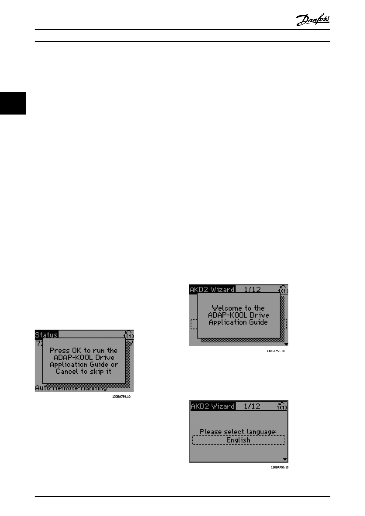
The ADAP-KOOL Drive AKD 102 will initially start up with the Application guide (each time until it has been run), thereafter
in the event of power failure the application guide is accessed through the Quick menu screen.
If “Cancel” is pressed, the AKD 102 will return to the status screen. An automatic timer will cancel the wizard after 5 min. of
inactivity (no buttons pressed). The wizard must be re-entered through the Quick Menu when it has been run once.
Answering the questions on the screens will take the user though a complete setup for the ADAP-KOOL Drive. Most
standard refrigeration applications can be setup by using this Application Guide. Advanced features must be accessed
though the menu structure (Quick Menu or Main Menu) in the drive.
The Application guide covers all standard settings for:
- Compressors
- Single fan and pump
- Condenser fans
After completing setup, choose to re-run wizard or start application
The Application Guide can be cancelled at any time by pressing “Back”. The Application Guide can be re-entered through
the Quick Menu. When re-entering the Application Guide, the user will be asked to keep previous changes to the factory
setup or to restore default values.
®
Drive Application Guide
The ADAP-KOOL Drive AKD 102 will start up initially with
the Application guide thereafter in the event of power
failure the application guide is accessed through the Quick
menu screen.
The following screen will be presented:
If “Cancel” is pressed, the AKD 102 will return to the status
screen. An automatic timer will cancel the wizard after 5
min. of inactivity (no buttons pressed). The wizard must be
re-entered through the Quick Menu as described below.
If “OK” is pressed, the Application Guide will start with the
following screen:
This screen will automatically change to the first input
screen of the Application Guide:
12 MG.11.L4.02 - ADAP-KOOL® Drive
Page 13
Application Guide
3
ADAP-KOOL
®
Drive Operating Instructions
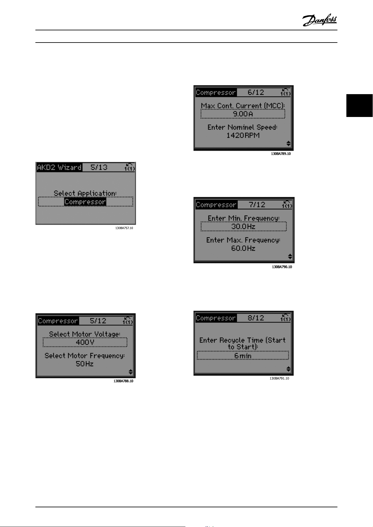
Answering the questions on the screens will take the user
though a complete setup for the ADAP-KOOL Drive. Most
standard refrigeration applications can be setup by using
this Application Guide. Advanced features must be
accessed though the menu structure (Quick Menu, Main
Menu etc.) in the drive.
The Application guide covers all standard settings for:
- Compressors
- Single fan and pump
- Condenser fans
Current and nominal speed setup
3
Min. and max. frequency setup
Compressor pack setup
As an example, please see screens below for a compressor
pack setup:
Voltage and frequency setup
Min. time between two starts
MG.11.L4.02 - ADAP-KOOL® Drive 13
Page 14
Application Guide
ADAP-KOOL
®
Drive Operating Instructions
3
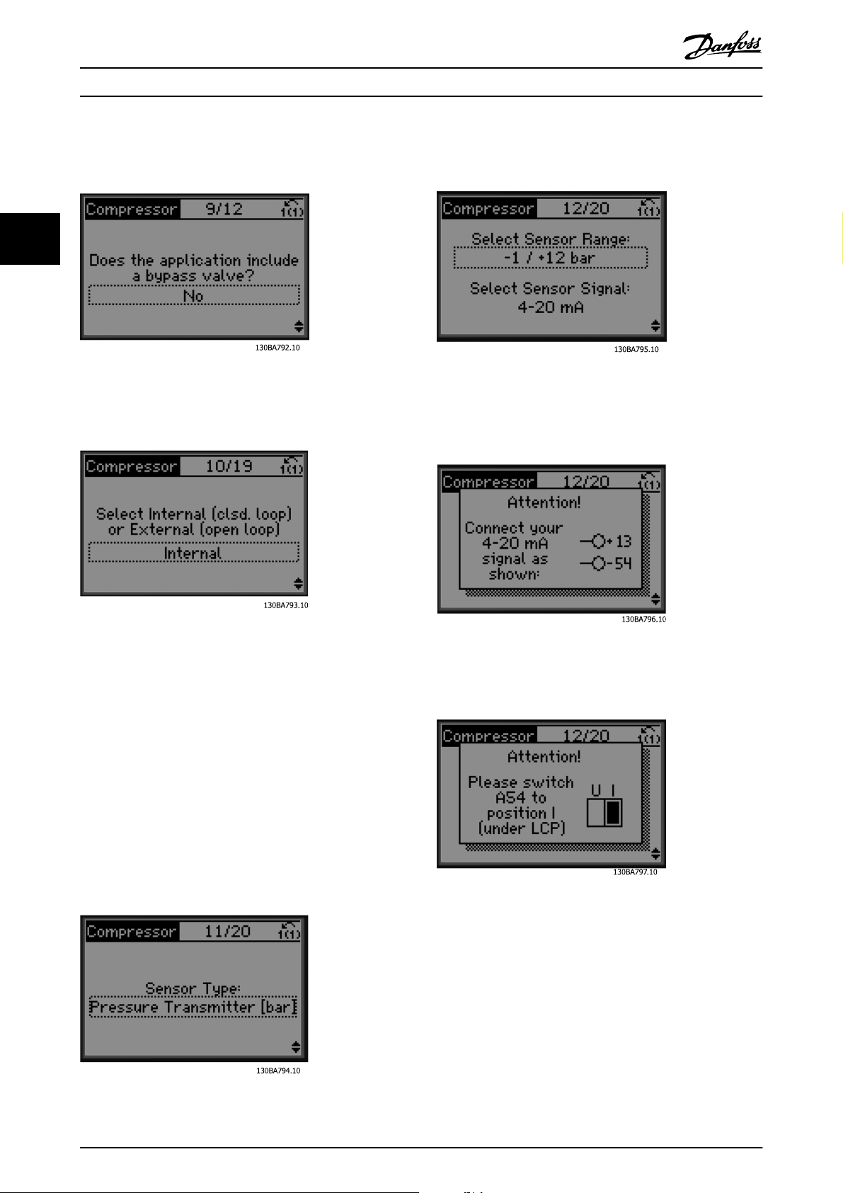
Choose with/ without bypass valve
Select open or closed loop
Settings for sensor
Info: 4-20 mA feedback chosen - please connect
accordingly
NOTE
Internal / Closed loop : The AKD 102 will control the
application directly using the internal PID control within
the drive and needs an input from an external input such
as a temperature or other sensor which is wired directly
into the drive and controls from the sensor signal.
External / Open loop: The AKD 102 takes its control signal
from another controller (such as a pack controller) which
gives the drive e.g. 0-10v, 4-20 mA or ADAP-KOOL Lon.
The drive will change its speed depending upon this
reference signal.
Select sensor type
Info: Set switch accordingly
14 MG.11.L4.02 - ADAP-KOOL® Drive
Page 15
Application Guide
3
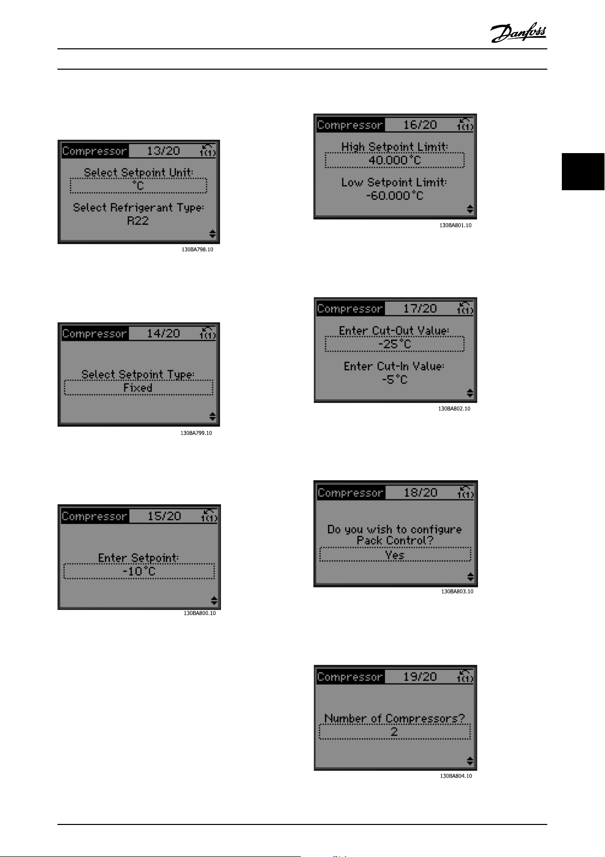
Select unit and conversion from pressure
Select fixed or floating setpoint
ADAP-KOOL
®
Drive Operating Instructions
Set cut out/ in value
3
Set setpoint
Set high/ low limit for setpoint
Choose pack control setup
Set number of compressors in pack
MG.11.L4.02 - ADAP-KOOL® Drive 15
Page 16
3
Application Guide
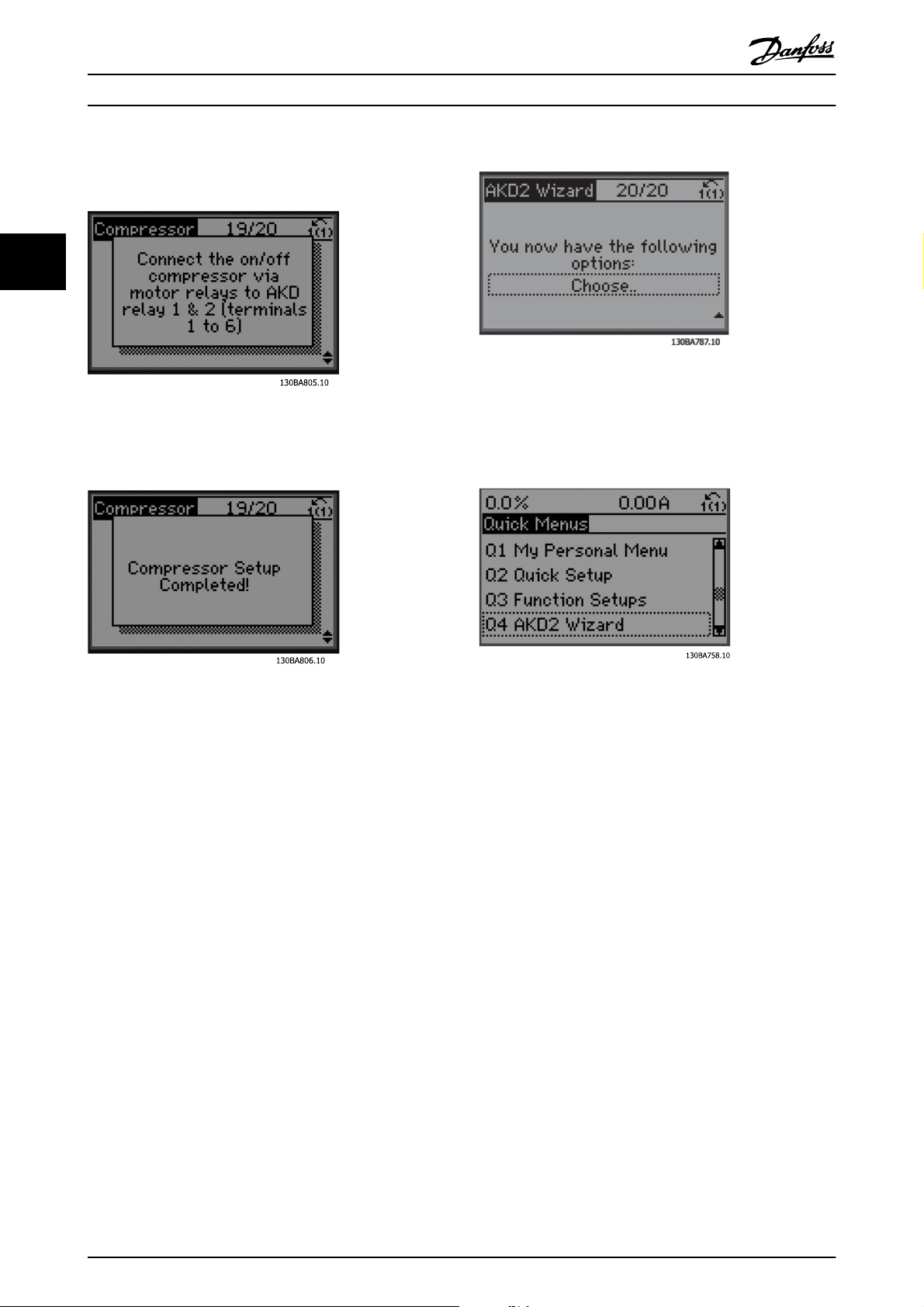
Info: Connect accordingly
Info: Setup completed
ADAP-KOOL
®
Drive Operating Instructions
The Application Guide can be cancelled at any time by
pressing “Back”. The Application Guide can be re-entered
through the Quick Menu:
After completing setup, choose to re-run wizard or start
application. Here we can select the following options:
Re-run wizard
•
Go to main menu
•
Go to status
•
Run AMA - Note this is a reduced AMA if
•
compressor application is selected and full AMA if
single fan and pump is selected.
If condenser fan is selected in application NO
•
AMA can be run.
Run application- this mode starts the drive in
•
either hand / local mode or via an external
control signal if open loop is selected in an earlier
screen
When re-entering the Application Guide, the user will be
asked to keep previous changes to the factory setup or to
restore default values.
NOTE
If the system requirement is to have the internal pack
controller for 3 compressors plus by-pass valve connected,
there is the need to specify AKD 102 with the extra relay
card (MCB105) mounted inside the drive.
The bypass valve must be programmed to operate from
one of the extra relay outputs on the MCB105 board.
This is needed because the standard relay outputs in the
AKD 102 are used to control the compressors in the pack.
16 MG.11.L4.02 - ADAP-KOOL® Drive
Page 17
Application Guide
3
ADAP-KOOL
®
Drive Operating Instructions
3.1.2 Application Descriptions
The AKD Wizard is structured into three basic applications:
Compressor
•
Multi condenser fan
•
Single fan and pump
•
These applications are then further expanded to allow control of the drive to be controlled via the drives own internal PID
controllers or from an external control signal.
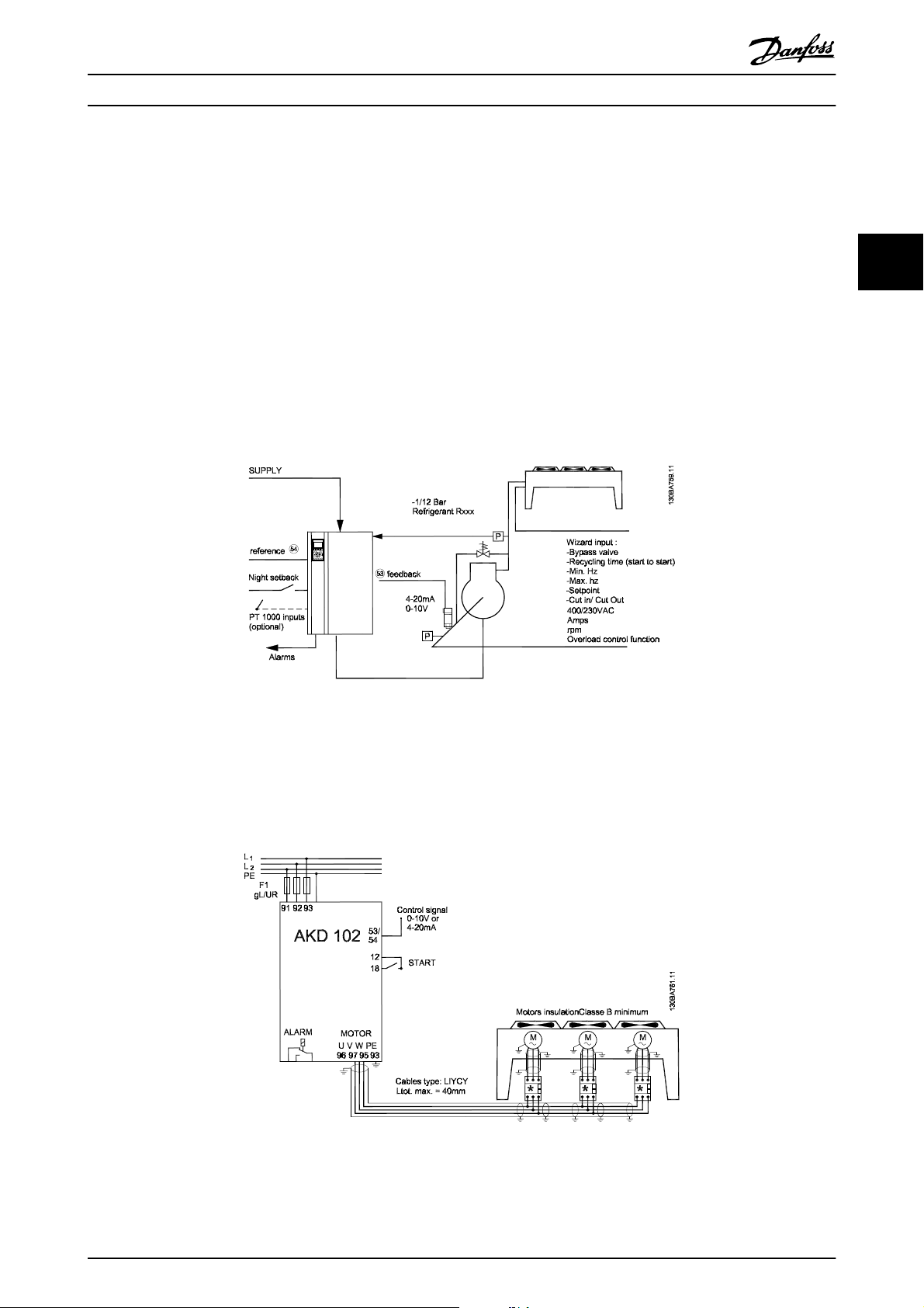
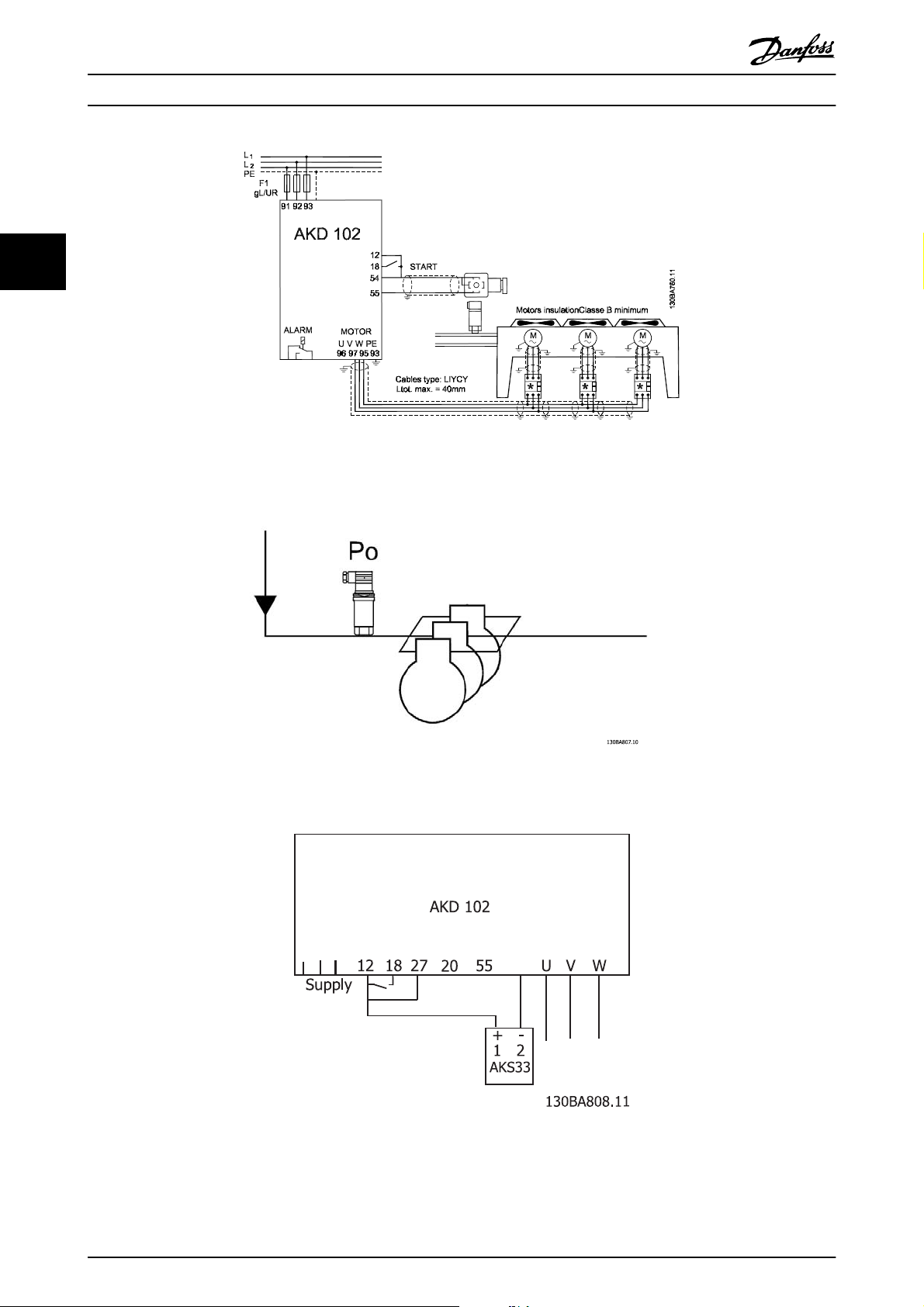
Compressor
The wizard guides the user through the set up of a refrigeration compressor by asking him to input data about the
compressor and the refrigeration system on which the drive will be running. All terminology and units used within the
wizard are common refrigeration type and set up is thus completed in 10-15 easy steps using just two buttons of the drives
local control panel.
3
Illustration 3.1 Standard drawing of “Compressor with internal control”
Single or multiple fans or pumps
The wizard guides the user through the set up of a refrigeration condenser fan or pump by asking him to input data about
the condenser or pump and the refrigeration system on which the drive will be running. All terminology and units used
within the wizard are common refrigeration type and set up is thus completed in 10-15 easy steps using just two buttons of
the drives local control panel.
Illustration 3.2 Speed control using analogue reference (open loop) – single fan or pump / multiple fans or pumps in parallel
MG.11.L4.02 - ADAP-KOOL® Drive 17
Page 18
3
Application Guide
Illustration 3.3 Pressure control in closed loop – stand alone system. single fan or pump / multiple fans or pumps in parallel
Compressor pack
ADAP-KOOL
®
Drive Operating Instructions
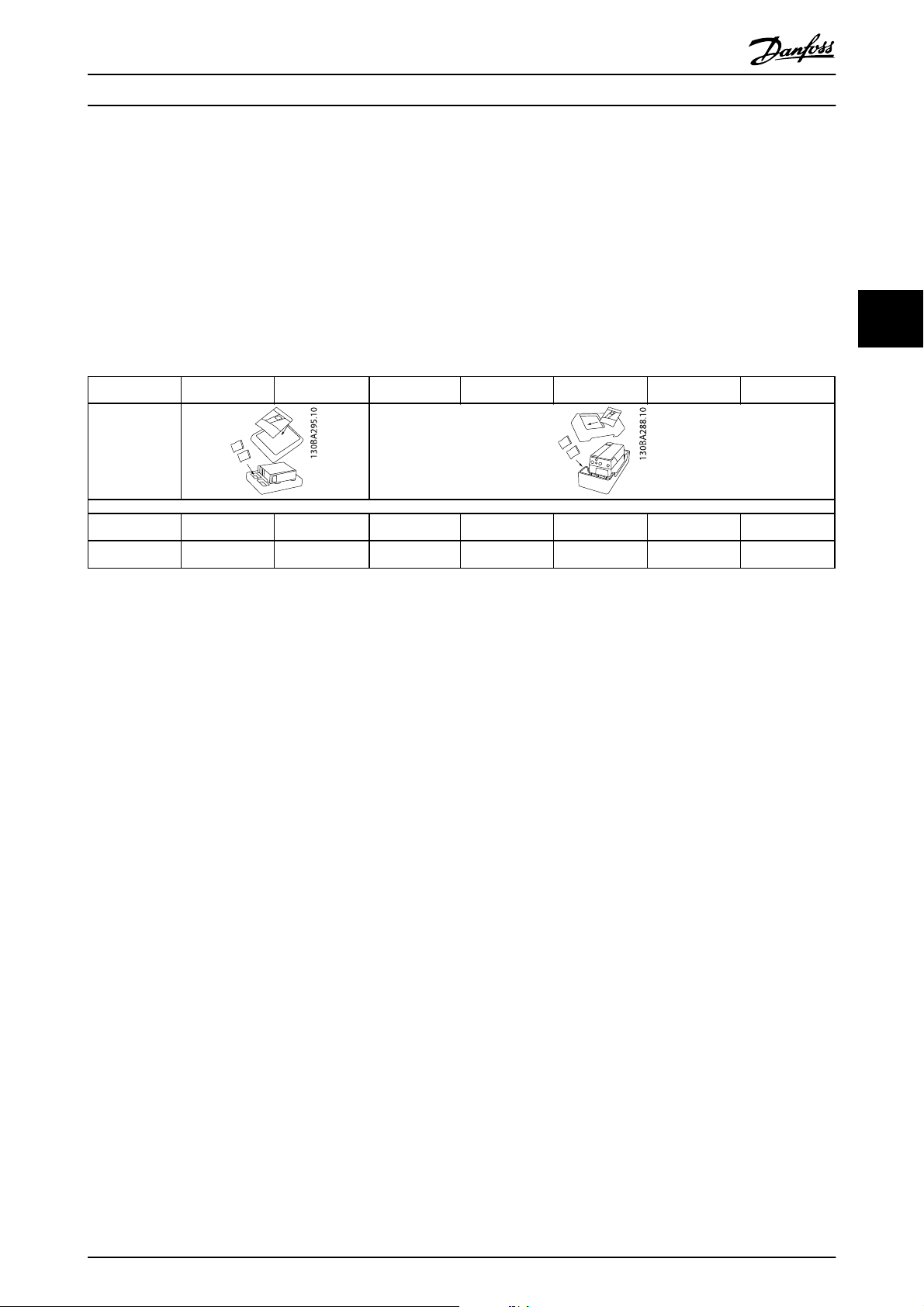
Illustration 3.4 P0 pressure transmitter
54
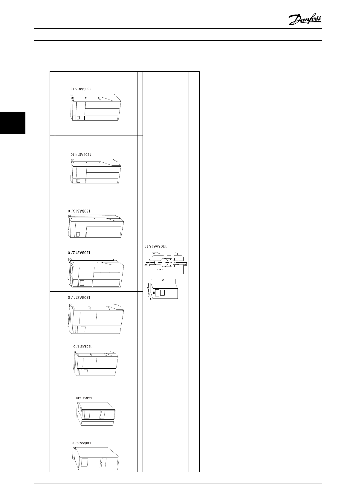
Illustration 3.5 How to connect the AKD102 and AKS33 for closed loop applications
18 MG.11.L4.02 - ADAP-KOOL® Drive
Page 19
Mechanical Installation
4
4 Mechanical Installation
4.1 Before starting
4.1.1 Checklist
ADAP-KOOL
®
Drive Operating Instructions
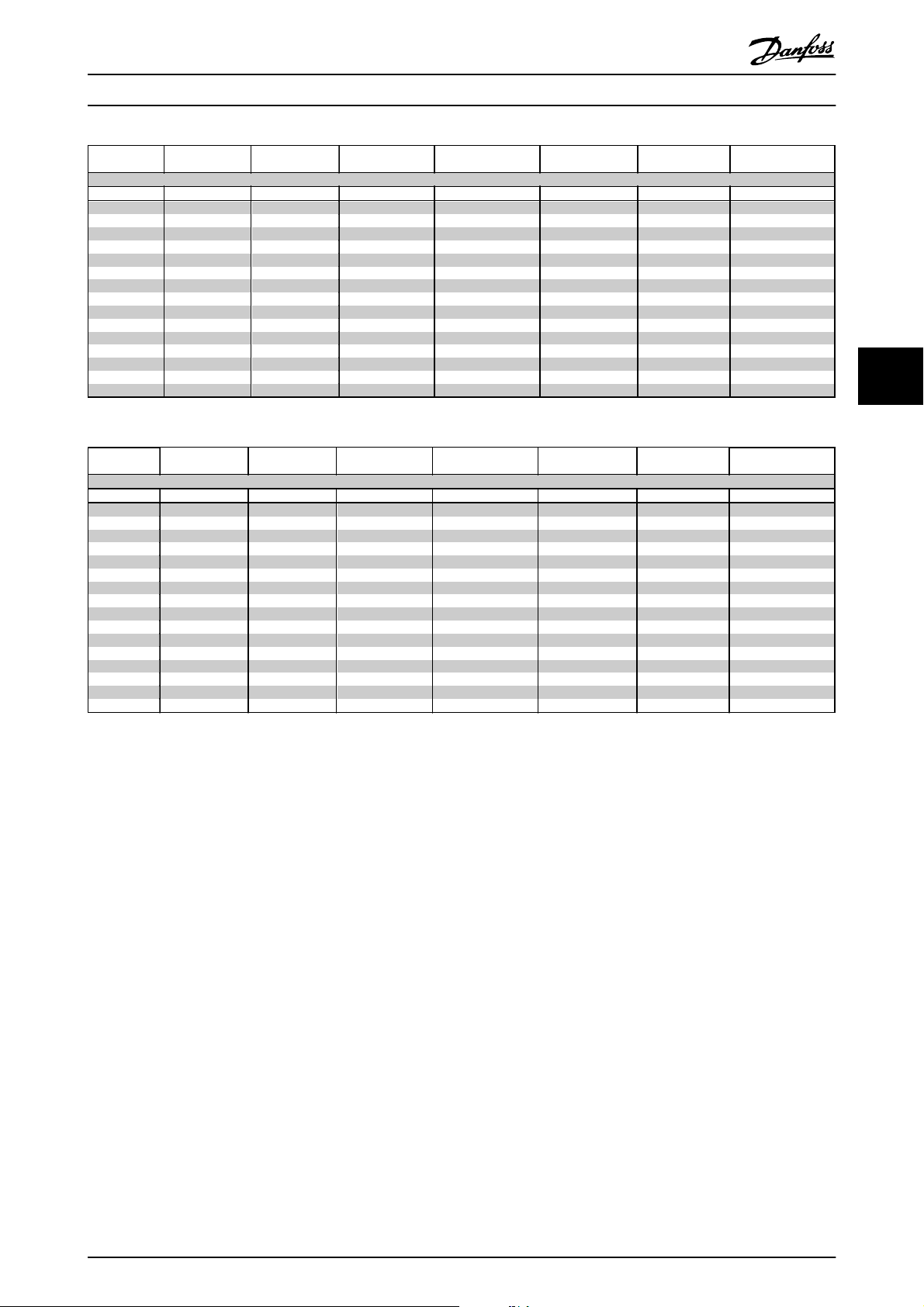
When unpacking the frequency converter, ensure that the unit is undamaged and complete. Use the following table to
identify the packaging:
Enclosure type:
Unit size (kW):
200-240 V 1.1-3.0 3.7 1.1-3.7
380-480 V 1.1-4.0 5.5-7.5 1.1-7.5
Table 4.1 Unpacking table
A2
(IP 20-21)
A3
(IP 20-21)
A4/A5
(IP 55-66)
B1 (IP 21-55-66) B2 (IP 21-55-66)
5.5-11/
5.5-11
11-18.5/
11-18.5
15/
15-18.5
22-30/
22-37
C1
(IP 21-55-66)
18.5-30/
22-30
37-55/
45-55
C2
(IP 21-55-66)
37-45/
37-45
75-90/
75-90
Please note that a selection of screwdrivers (phillips or cross-thread screwdriver and torx), a side-cutter, drill and knife is also
recommended to have handy for unpacking and mounting the frequency converter. The packaging for these enclosures
contains, as shown: Accessories bag(s), documentation and the unit. Depending on options fitted there may be one or two
bags and one or more booklets.
4
MG.11.L4.02 - ADAP-KOOL® Drive 19
Page 20
4
Mechanical Installation
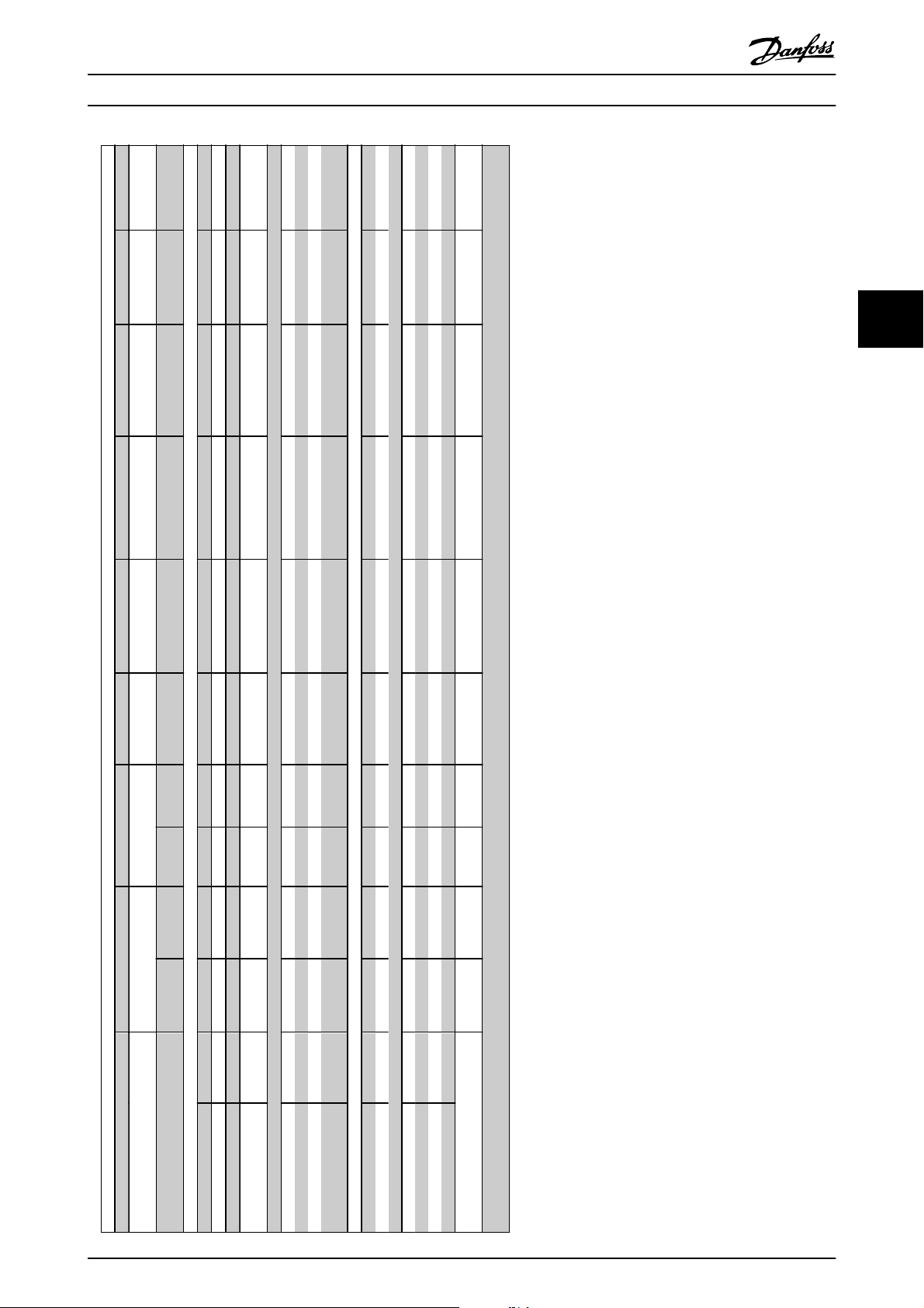
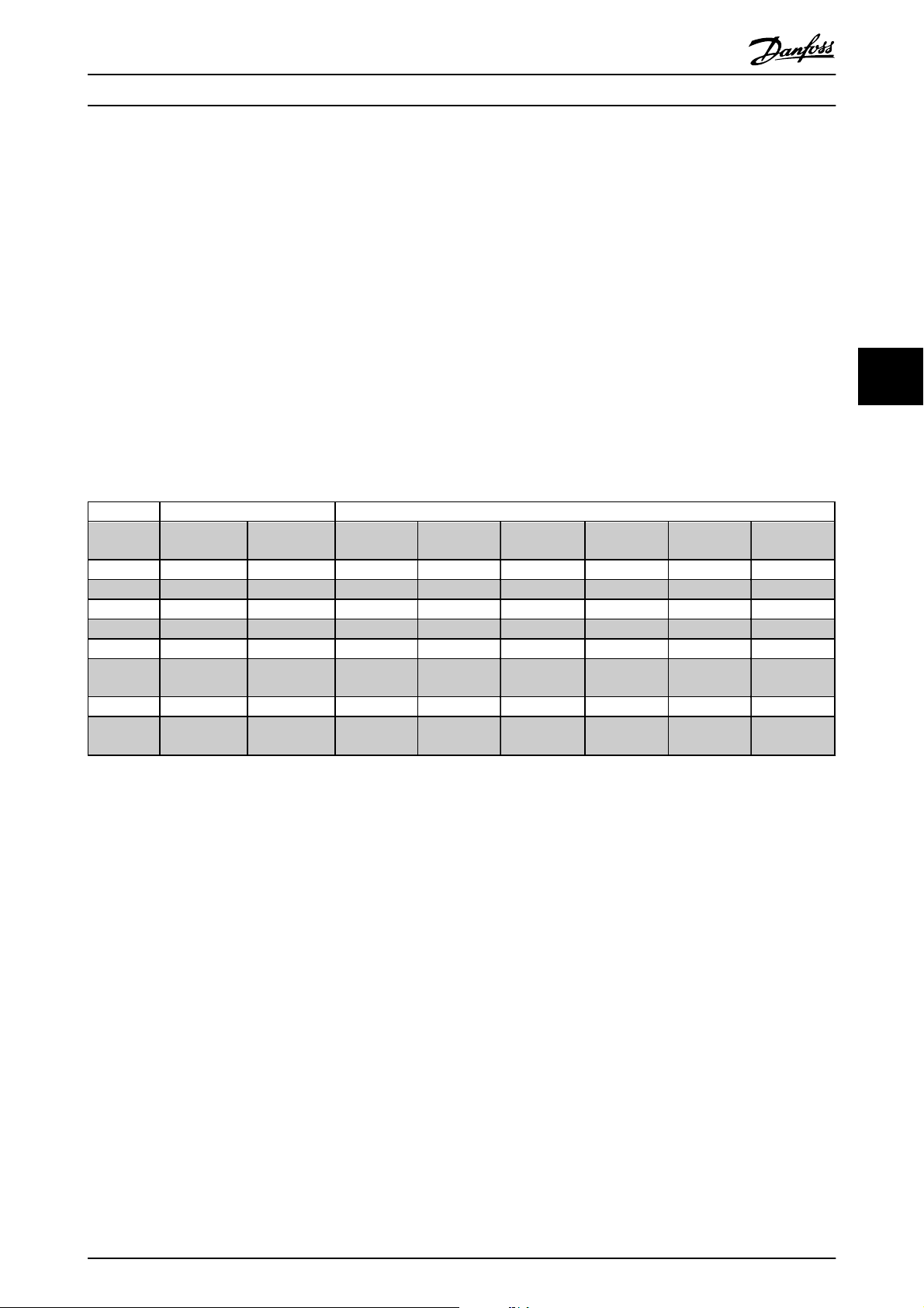
4.1.2 Mechanical Dimensions
ADAP-KOOL
®
Drive Operating Instructions
* A5 in IP55/66 only
All measurements in mm.
A2 A3 A4 A5 B1 B2 C1 C2
IP20/21 IP20/21 IP55/66 IP55/66 IP21/55/66 IP21/55/66 IP21/55/66 IP21/55/66
20 MG.11.L4.02 - ADAP-KOOL® Drive
Page 21
Mechanical Installation
4
37-45
75-90
21/55/66
Type 1/12
37-55
18.5-30
21/55/66
Type 1/12
15
22-30
21/55/66
Type 1/12
5.5-11
11-18.5
21/ 55/66
Type 1/12
ADAP-KOOL
®
Drive Operating Instructions
4
Mechanical dimensions
1.1-3.7
1.1-7.5
1.1-2.2
1.1-4.0
3.7
5.5-7.5
1.1-3.0
1.1-4.0
55/66
Type 12
55/66
21
Type 1
20
Chassis
21
Type 1
20
Chassis
a 257 350 257 350 401 402 454 624 648 739
b 70 70 110 110 171 215 210 210 272 334
4.9 5.3 6.6 7.0 9.7 14 23 27 45 65
f 9 9 9 9 6 9 9 9 9.8 9.8
c 8.0 8.0 8.0 8.0 8.2 8.2 12 12 12 12
Frame size (kW): A2 A3 A4 A5 B1 B2 C1 C2
IP
NEMA
Enclosure A** 246 372 246 372 390 420 480 650 680 770
Back plate A1 268 375 268 375 390 420 480 650 680 770
Width (mm)
Enclosure B 90 90 130 130 200 242 242 242 308 370
With one C option B 130 130 170 170 242 242 242 308 370
Distance between mount.
holes
Without option A/B C 205 205 205 205 175 200 260 260 310 335
Screw holes (mm)
200-240 V
380-480 V
..with de-coupling plate A2 374 - 374 - - - - - - -
Distance between mount.
Height (mm)
holes
Back plate B 90 90 130 130 200 242 242 242 308 370
Depth (mm)
With option A/B C* 220 220 220 220 175 200 260 260 310 335
Diameter ø d 11 11 11 11 12 12 19 19 19 19
Diameter ø e 5.5 5.5 5.5 5.5 6.5 6.5 9 9 9.0 9.0
Max weight
(kg)
* Depth of enclosure will vary with different options installed.
** The free space requirements are above and below the bare enclosure height measurement A. See section 3.2.3 for further information.
MG.11.L4.02 - ADAP-KOOL® Drive 21
Page 22

Mechanical Installation
ADAP-KOOL
®
Drive Operating Instructions
4.1.3 Accessory Bags
Accessory Bags: Find the following parts included in the frequency converter accessory bags
4
Frame sizes A2 and A3 Frame size A4/A5
Frame sizes B1 and B2 Frame sizes C1 and C2
1 + 2 only available in units with brake chopper. For DC link connection (Load sharing) the connector 1 can be ordered separately.
An eight pole connector is included in accessory bag for AKD 102 without Safe Stop.
22 MG.11.L4.02 - ADAP-KOOL® Drive
Page 23
Mechanical Installation
4
ADAP-KOOL
®
Drive Operating Instructions
4.2 How to Install
4.2.1 Mechanical Mounting
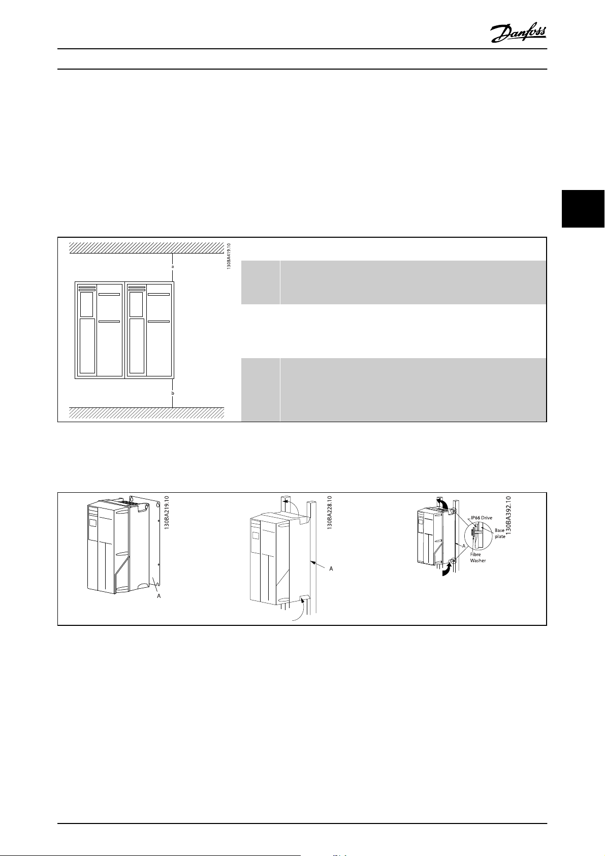
All IP20 enclosure sizes as well as IP21/ IP55 enclosure sizes except A2 and A3 allow side-by-side installation.
If the IP 21 Enclosure kit (130B1122 or 130B1123) is used on enclosure A2 or A3, there must be a clearance between the
drives of min. 50 mm.
For optimal cooling conditions allow a free air passage above and below the frequency converter. See table below.
Air passage for different enclosures
Enclosure: A2 A3 A4 A5 B1 B2 C1 C2
a (mm): 100 100 100 100 200 200 200 225
b (mm): 100 100 100 100 200 200 200 225
1. Drill holes in accordance with the measurements given.
2. You must provide screws suitable for the surface on which you want to mount the frequency converter. Re-tighten
all four screws.
4
Table 4.2 Mounting frame sizes A5, B1, B2, C1 and C2 on a non-solid back wall, the drive must be provided with a back plate A
due to insufficient cooling air over the heat sink.
MG.11.L4.02 - ADAP-KOOL® Drive 23
Page 24

4
Mechanical Installation
ADAP-KOOL
®
Drive Operating Instructions
4.2.2 Safety Requirements of Mechanical Installation
WARNING
Pay attention to the requirements that apply to integration and field mounting kit. Observe the information in the list to
avoid serious injury or equipment damage, especially when installing large units.
NOTE
The frequency converter is cooled by means of air circulation.
To protect the unit from overheating, it must be ensured that the ambient temperature does not exceed the maximum
temperature stated for the frequency converter and that the 24-hour average temperature is not exceeded. Locate the
maximum temperature and 24-hour average in the paragraph Derating for Ambient Temperature.
If the ambient temperature is in the range of 45 °C - 55 ° C, derating of the frequency converter will become relevant, see
Derating for Ambient Temperature.
The service life of the frequency converter is reduced if derating for ambient temperature is not taken into account.
4.2.3 Field Mounting
For field mounting the IP 21/IP 4X top/TYPE 1 kits or IP 54/55 units are recommended.
4.2.4 Panel Through Mounting
A Panel Through Mount Kit is available for frequency converter series ADAP-KOOL Drive.
In order to increase heatsink cooling and reduce panel depth, the frequency converter may be mounted in a through panel.
Furthermore the in-built fan can then be removed.
The kit is available for enclosures A5 through C2.
NOTE
This kit cannot be used with cast front covers. No cover or IP21 plastic cover must be used instead.
Information on ordering numbers is found in the Design Guide, section Ordering Numbers.
More detailed information is available in the Panel Through Mount Kit instruction, MI.33.H1.YY, where yy=language code.
24 MG.11.L4.02 - ADAP-KOOL® Drive
Page 25
Electrical Installation
5
ADAP-KOOL
®
Drive Operating Instructions
5 Electrical Installation
5.1 How to Connect
5.1.1 Cables General
NOTE
For the AKDHigh Power series mains and motor connections, please see the ADAP-KOOL® Drive AKD102High Power
Operating Instructions, MG.11.Ox.yy.
NOTE
Cables General
Always comply with national and local regulations on cable cross-sections.
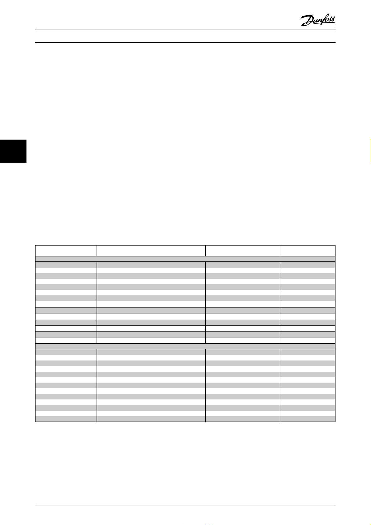
Details of terminal tightening torques.
Power (kW) Torque (Nm)
Enclo-
sure
A2 1.1 - 3.0 1.1 - 4.0 1.8 1.8 1.8 1.8 3 0.6
A3 3.7 5.5 - 7.5 1.8 1.8 1.8 1.8 3 0.6
A4 1.1 - 2.2 1.4 - 4 1.8 1.8 1.8 1.8 3 0.6
A5 1.1 - 3.7 1.1 - 7.5 1.8 1.8 1.8 1.8 3 0.6
B1 5.5 - 11 11 - 18.5 1.8 1.8 1.5 1.5 3 0.6
B2
C1 18.5 - 30 37 - 55 10 10 10 10 3 0.6
C2
200-240
V
-
15
37
45
380-480
V
22
30
75
90
Line Motor
2.5
4.5
14
24
2.5
4.5
14
24
DC
connection
3.7
3.7
14
14
Brake Earth Relay
3.7
3.7
14
14
3
3
3
3
5
0.6
0.6
0.6
0.6
Table 5.1 Tightening of terminals
MG.11.L4.02 - ADAP-KOOL® Drive 25
Page 26
5
Electrical Installation
ADAP-KOOL
®
Drive Operating Instructions
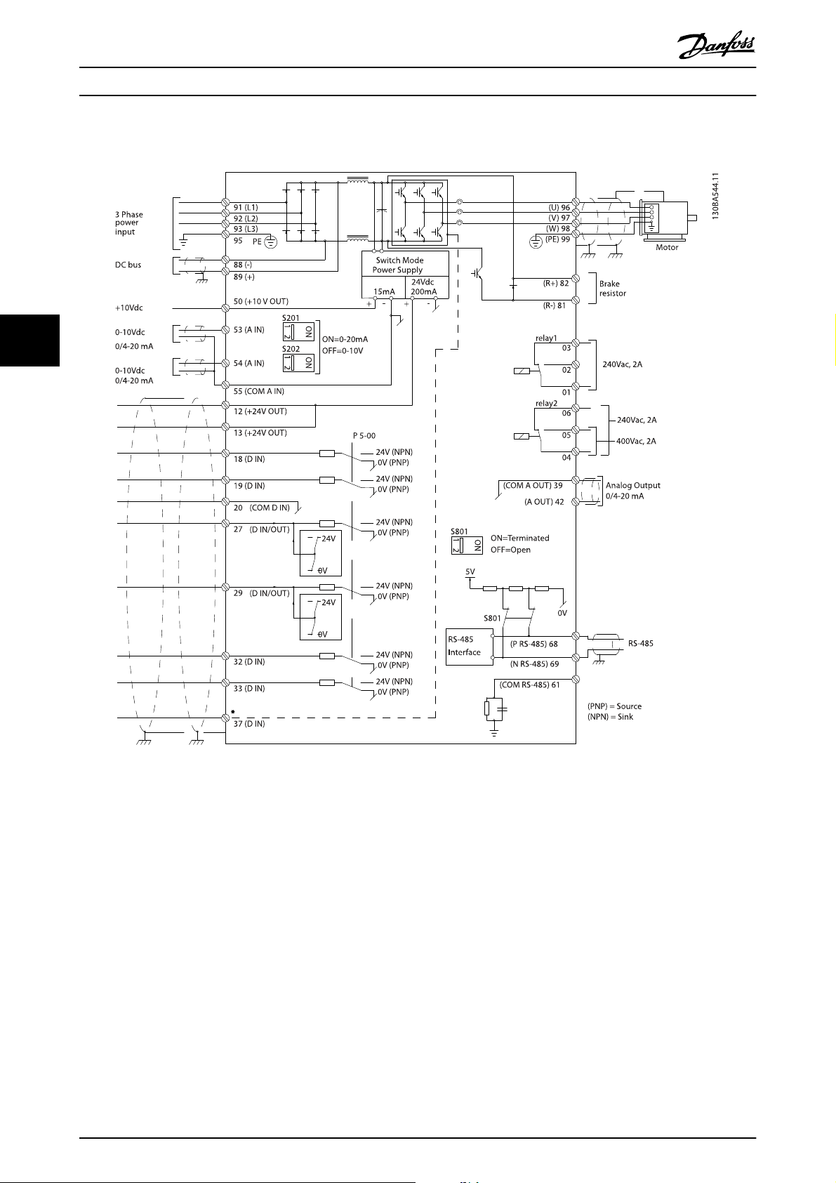
5.1.2 Electrical Installation and Control Cables
Illustration 5.1 Diagram showing all electrical terminals. (Terminal 37 present for units with Safe Stop Function only.)
26 MG.11.L4.02 - ADAP-KOOL® Drive
Page 27

Electrical Installation
5
Terminal number Terminal description Parameter number Factory default
1+2+3 Terminal 1+2+3-Relay1 5-40 Alarm Running
4+5+6 Terminal 4+5+6-Relay2 5-40 Alarm Running
12 Terminal 12 Supply - +24 V DC
13 Terminal 13 Supply - +24 V DC
18 Terminal 18 Digital Input 5-10 Start
19 Terminal 19 Digital Input 5-11 Reversing
20 Terminal 20 - Common
27 Terminal 27 Digital Input/Output 5-12/5-30 Coast inverse
29 Terminal 29 Digital Input/Output 5-13/5-31 Jog
32 Terminal 32 Digital Input 5-14 No operation
33 Terminal 33 Digital Input 5-15 No operation
37 Terminal 37 Digital Input - Safe Stop
42 Terminal 42 Analog Output 6-50 Speed 0-HighLim
53 Terminal 53 Analog Input 3-15/6-1*/20-0* Reference
54 Terminal 54 Analog Input 3-15/6-2*/20-0* Feedback
Table 5.2 Terminal connections
Very long control cables and analog signals may, in rare cases and depending on installation, result in 50/60 Hz earth loops
due to noise from mains supply cables.
ADAP-KOOL
®
Drive Operating Instructions
5
If this occurs, break the screen or insert a 100 nF capacitor between screen and chassis.
NOTE
The common of digital / analog inputs and outputs should be connected to separate common terminals 20, 39, and 55. This
will avoid ground current interference among groups. For example, it avoids switching on digital inputs disturbing analog
inputs.
NOTE
Control cables must be screened/armoured.
MG.11.L4.02 - ADAP-KOOL® Drive 27
Page 28
Electrical Installation
ADAP-KOOL
®
Drive Operating Instructions
5.1.3 Fuses
Branch circuit protection
In order to protect the installation against electrical and fire hazard, all branch circuits in an installation, switch gear,
machines etc., must be shortcircuit and overcurrent protected according to the national/international regulations.
Short circuit protection
The frequency converter must be protected against short-circuit to avoid electrical or fire hazard. Danfoss recommends
using the fuses mentioned in tables 4.3 and 4.4 to protect service personnel or other equipment in case of an internal
failure in the unit. The frequency converter provides full short circuit protection in case of a short-circuit on the motor
output.
5
Over-current protection
Provide overload protection to avoid fire hazard due to overheating of the cables in the installation. Over current protection
must always be carried out according to national regulations. The frequency converter is equipped with an internal over
®
current protection that can be used for upstream overload protection (UL-applications excluded). See ADAP-KOOL
Drive
AKD102 Programming Guide, par. 4-18. Fuses must be designed for protection in a circuit capable of supplying a maximum
of 100,000 A
(symmetrical), 500 V/600 V maximum.
rms
Non UL compliance
If UL/cUL is not to be complied with, Danfoss recommends using the fuses mentioned in table 4.2, which will ensure
compliance with EN50178:
In case of malfunction, not following the recommendation may result in unnecessary damage to the frequency converter.
Frequency
converter
200-240 V
K25-K75
1K1-1K5
2K2
3K0
3K7
5K5
7K5
11K
15K
18K5
22K
30K
37K
45K
380-480 V
K37-1K5
2K2-3K0
4K0-5K5
7K5
11K-15K
18K
22K
30K
37K
45K
55K
75K
90K
Max. fuse size
1
10A
1
16A
1
25A
1
25A
1
35A
1
50A
1
63A
1
63A
1
80A
1
125A
1
125A
1
160A
1
200A
1
250A
1
10A
1
16A
1
25A
1
35A
1
63A
1
63A
1
63A
1
80A
1
100A
1
125A
1
160A
1
250A
1
250A
Voltage Type
200-240 V type gG
200-240 V type gG
200-240 V type gG
200-240 V type gG
200-240 V type gG
200-240 V type gG
200-240 V type gG
200-240 V type gG
200-240 V type gG
200-240 V type gG
200-240 V type gG
200-240 V type gG
200-240 V type aR
200-240 V type aR
380-500 V type gG
380-500 V type gG
380-500 V type gG
380-500 V type gG
380-500 V type gG
380-500 V type gG
380-500 V type gG
380-500 V type gG
380-500 V type gG
380-500 V type gG
380-500 V type gG
380-500 V type aR
380-500 V type aR
Table 5.3 Non UL fuses 200 V to 480 V
1) Max. fuses - see national/international regulations for selecting an applicable fuse size.
*170M fuses from Bussmann shown use the -/80 visual indicator, -TN/80 Type T, -/110 or TN/110 Type T indicator fuses of
the same size and amperage may be substituted for external use.
28 MG.11.L4.02 - ADAP-KOOL® Drive
Page 29
Electrical Installation
5
ADAP-KOOL
®
Drive Operating Instructions
Frequency
converter
UL Compliance - 200-240 V
kW Type RK1 Type J Type T Type RK1 Type RK1 Type CC Type RK1
K25-K37 KTN-R05 JKS-05 JJN-05 5017906-005 KLN-R005 ATM-R05 A2K-05R
K55-1K1 KTN-R10 JKS-10 JJN-10 5017906-010 KLN-R10 ATM-R10 A2K-10R
1K5 KTN-R15 JKS-15 JJN-15 5017906-015 KLN-R15 ATM-R15 A2K-15R
2K2 KTN-R20 JKS-20 JJN-20 5012406-020 KLN-R20 ATM-R20 A2K-20R
3K0 KTN-R25 JKS-25 JJN-25 5012406-025 KLN-R25 ATM-R25 A2K-25R
3K7 KTN-R30 JKS-30 JJN-30 5012406-030 KLN-R30 ATM-R30 A2K-30R
5K5 KTN-R50 JKS-50 JJN-50 5012406-050 KLN-R50 - A2K-50R
7K5 KTN-R50 JKS-60 JJN-60 5012406-050 KLN-R60 - A2K-50R
11K KTN-R60 JKS-60 JJN-60 5014006-063 KLN-R60 A2K-60R A2K-60R
15K KTN-R80 JKS-80 JJN-80 5014006-080 KLN-R80 A2K-80R A2K-80R
18K5 KTN-R125 JKS-150 JJN-125 2028220-125 KLN-R125 A2K-125R A2K-125R
22K KTN-R125 JKS-150 JJN-125 2028220-125 KLN-R125 A2K-125R A2K-125R
30K FWX-150 - - 2028220-150 L25S-150 A25X-150 A25X-150
37K FWX-200 - - 2028220-200 L25S-200 A25X-200 A25X-200
45K FWX-250 - - 2028220-250 L25S-250 A25X-250 A25X-250
Bussmann Bussmann Bussmann SIBA Littel fuse
Ferraz-
Shawmut
Shawmut
Table 5.4 UL fuses 200 - 240 V
Frequency
converter
UL Compliance - 380-480 V, 525-600
kW Type RK1 Type J Type T Type RK1 Type RK1 Type CC Type RK1
K37-1K1 KTS-R6 JKS-6 JJS-6 5017906-006 KLS-R6 ATM-R6 A6K-6R
1K5-2K2 KTS-R10 JKS-10 JJS-10 5017906-010 KLS-R10 ATM-R10 A6K-10R
3K0 KTS-R15 JKS-15 JJS-15 5017906-016 KLS-R16 ATM-R16 A6K-16R
4K0 KTS-R20 JKS-20 JJS-20 5017906-020 KLS-R20 ATM-R20 A6K-20R
5K5 KTS-R25 JKS-25 JJS-25 5017906-025 KLS-R25 ATM-R25 A6K-25R
7K5 KTS-R30 JKS-30 JJS-30 5012406-032 KLS-R30 ATM-R30 A6K-30R
11K KTS-R40 JKS-40 JJS-40 5014006-040 KLS-R40 - A6K-40R
15K KTS-R40 JKS-40 JJS-40 5014006-040 KLS-R40 - A6K-40R
18K KTS-R50 JKS-50 JJS-50 5014006-050 KLS-R50 - A6K-50R
22K KTS-R60 JKS-60 JJS-60 5014006-063 KLS-R60 - A6K-60R
30K KTS-R80 JKS-80 JJS-80 2028220-100 KLS-R80 - A6K-80R
37K KTS-R100 JKS-100 JJS-100 2028220-125 KLS-R100 A6K-100R
45K KTS-R125 JKS-150 JJS-150 2028220-125 KLS-R125 A6K-125R
55K KTS-R150 JKS-150 JJS-150 2028220-160 KLS-R150 A6K-150R
75K FWH-220 - - 2028220-200 L50S-225 A50-P225
90K FWH-250 - - 2028220-250 L50S-250 A50-P250
Bussmann Bussmann Bussmann SIBA Littel fuse
Ferraz-
Shawmut
Shawmut
Ferraz-
5
Ferraz-
Table 5.5 UL fuses 380 - 600 V
KTS-fuses from Bussmann may substitute KTN for 240 V frequency converters.
FWH-fuses from Bussmann may substitute FWX for 240 V frequency converters.
KLSR fuses from LITTEL FUSE may substitute KLNR fuses for 240 V frequency converters.
L50S fuses from LITTEL FUSE may substitute L50S fuses for 240 V frequency converters.
A6KR fuses from FERRAZ SHAWMUT may substitute A2KR for 240 V frequency converters.
A50X fuses from FERRAZ SHAWMUT may substitute A25X for 240 V frequency converters.
MG.11.L4.02 - ADAP-KOOL® Drive 29
Page 30
5
Electrical Installation
ADAP-KOOL
®
Drive Operating Instructions
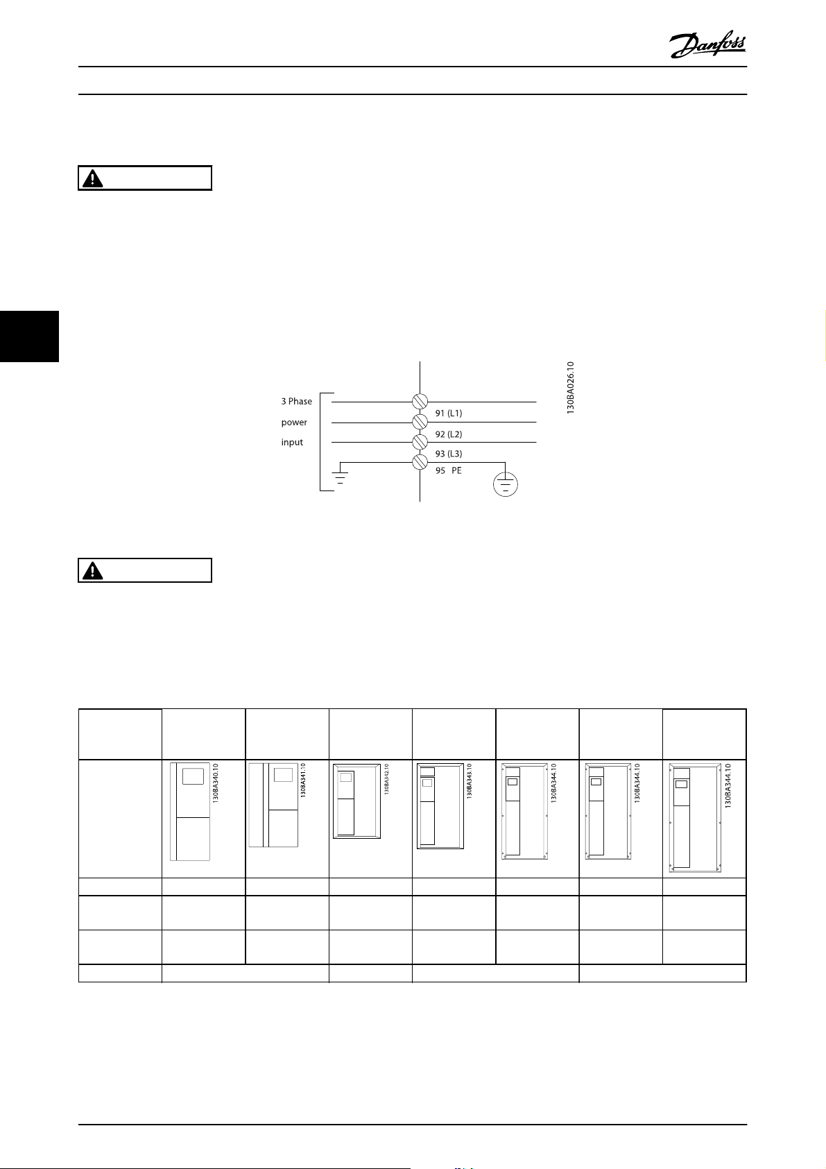
5.1.4 Earthing and IT mains
WARNING
The earth connection cable cross section must be at least 10 mm2 or 2 rated mains wires terminated separately according
to EN 50178 or IEC 61800-5-1 unless national regulations specify differently. Always comply with national and local
regulations. on cable cross-sections.
The mains is connected to the main disconnect switch if this is included.
NOTE
Check that mains voltage corresponds to the mains voltage of the frequency converter name plate.
Illustration 5.2 Terminals for mains and earthing.
WARNING
IT Mains
Do not connect 400 V frequency converters with RFI-filters to mains supplies with a voltage between phase and earth of
more than 440 V.
For IT mains and delta earth (grounded leg), mains voltage may exceed 440 V between phase and earth.
5.1.5 Mains Wiring Overview
Enclosure:
Motor size:
200-240 V
380-480 V
Goto: 5.1.6 5.1.7 5.1.8 5.1.9
A2
(IP 20/IP 21)A3(IP 20/IP 21)A5(IP 55/IP 66)
1.1-3.0
kW
1.1-4.0
kW
3.7
kW
5.5-7.5
kW
1.1-3.7
kW
1.1-7.5
kW
B1
(IP 21/IP 55/IP
66)
5.5-11
kW
11-18.5
kW
B2
(IP 21/IP 55/IP
66)
15
kW
22-30
kW
C1
(IP 21/IP 55/66)C2(IP 21/IP 55/66)
18.5-30
kW
37-55
kW
37-45
kW
75-90
kW
Table 5.6 Mains wiring table.
30 MG.11.L4.02 - ADAP-KOOL® Drive
Page 31

Electrical Installation
5
ADAP-KOOL
5.1.6 Mains Connection for A2 and A3
®
Drive Operating Instructions
5
Illustration 5.3 First mount the two screws on the mounting plate, slide it into place and tighten fully.
Illustration 5.4 When mounting cables, first mount and tighten earth cable.
MG.11.L4.02 - ADAP-KOOL® Drive 31
Page 32

5
Electrical Installation
ADAP-KOOL
®
Drive Operating Instructions
WARNING
The earth connection cable cross section must be at least 10 mm2 or 2 rated mains wires terminated separately according
to EN 50178/IEC 61800-5-1.
Illustration 5.5 Then mount mains plug and tighten wires.
Illustration 5.6 Finally tighten support bracket on mains wires.
NOTE
With single phase A3 use L1 and L2 terminals.
32 MG.11.L4.02 - ADAP-KOOL® Drive
Page 33

Electrical Installation
5
5.1.7 Mains Connection for A5
ADAP-KOOL
®
Drive Operating Instructions
Illustration 5.7 How to connect to mains and earthing without mains disconnect switch. Note that a cable clamp is used.
Illustration 5.8 How to connect to mains and earthing with mains disconnect switch.
NOTE
With single phase A5 use L1 and L2 terminals.
5
MG.11.L4.02 - ADAP-KOOL® Drive 33
Page 34

5
Electrical Installation
ADAP-KOOL
®
Drive Operating Instructions
5.1.8 Mains Connection for B1 and B2
Illustration 5.9 How to connect to mains and earthing for B1 and B2.
NOTE
For correct cable dimensions please see the section General Specifications at the back of this manual.
5.1.9 Mains connection for C1 and C2
Illustration 5.10 How to connect to mains and earthing.
34 MG.11.L4.02 - ADAP-KOOL® Drive
Page 35

Electrical Installation
5
ADAP-KOOL
®
Drive Operating Instructions
5.1.10 How to Connect Motor - Introduction
See section General Specifications for correct dimensioning of motor cable cross-section and length.
Use a screened/armoured motor cable to comply with EMC emission specifications (or install the cable in metal
•
conduit).
Keep the motor cable as short as possible to reduce the noise level and leakage currents.
•
Connect the motor cable screen/armour to both the decoupling plate of the frequency converter and to the metal
•
of the motor. (Same applies to both ends of metal conduit if used instead of screen.)
Make the screen connections with the largest possible surface area (cable clamp or by using an EMC cable gland).
•
This is done by using the supplied installation devices in the frequency converter.
Avoid terminating the screen by twisting the ends (pigtails), as this will spoil high frequency screening effects.
•
If it is necessary to break the continuity of the screen to install a motor isolator or motor relay, the continuity must
•
be maintained with the lowest possible HF impedance.
Cable length and cross-section
The frequency converter has been tested with a given length of cable and a given cross-section of that cable. If the crosssection is increased, the cable capacitance - and thus the leakage current - may increase, and the cable length must be
reduced correspondingly.
Switching frequency
When frequency converters are used together with sine wave filters to reduce the acoustic noise from a motor, the
switching frequency must be set according to the sine wave filter instruction in 14-01 Switching Frequency.
Precautions while using Aluminium conductors
Aluminium conductors are not recommended for cable cross sections below 35 mm. Terminals can accept aluminium
conductors but the conductor surface has to be clean and the oxidation must be removed and sealed by neutral acid free
Vaseline grease before the conductor is connected.
Furthermore, the terminal screw must be retightened after two days due to the softness of the aluminium. It is crucial to
ensure the connection makes a gas tight joint, otherwise the aluminium surface will oxidize again.
All types of three-phase asynchronous standard motors can
be connected to the frequency converter. Normally, small
motors are star-connected (230/400 V, D/Y). Large motors
are delta-connected (400/690 V, D/Y). Refer to the motor
name plate for correct connection mode and voltage.
5
Illustration 5.11 Terminals for motor connection
NOTE
In motors without phase insulation paper or other insulation reinforcement suitable for operation with voltage supply (such
as a frequency converter), fit a sine-wave filter on the output of the frequency converter. (Motors that comply with IEC
60034-17 do not require a Sine-wave filter).
MG.11.L4.02 - ADAP-KOOL® Drive 35
Page 36

Electrical Installation
No. 96 97 98 Motor voltage 0-100% of mains voltage.
U1 V1 W1
U1 V1 W1 6 cables out of motor, Star-connected
U2, V2, W2 to be interconnected separately
(optional terminal block)
No. 99 Earth connection
PE
Table 5.7 3 and 6 cable motor connection.
U V W 3 cables out of motor
W2 U2 V2
ADAP-KOOL
6 cables out of motor, Delta-connected
®
Drive Operating Instructions
5
5.1.11 Motor Wiring Overview
Enclosure:
Motor size:
200-240 V
380-480 V
Goto: 5.1.12 5.1.13 5.1.13 5.1.14 5.1.15
Table 5.8 Motor wiring table.
A2
(IP 20/IP 21)A3(IP 20/IP 21)A4(IP 55/IP 66)A5(IP 55/IP 66)
1.1-3.0
kW
1.1-4.0
kW
3.7
kW
5.5-7.5
kW
0.25-2.2
kW
0.37-4.0
kW
1.1-3.7
kW
1.1-7.5
kW
B1
(IP 21/IP 55/
IP 66)
5.5-11
kW
11-18.5
kW
B2
(IP 21/IP 55/
IP 66)
15
kW
22-30
kW
C1
(IP 21/IP
55/66)
18.5-30
kW
37-55
kW
C2
(IP 21/IP
55/66)
37-45
kW
75-90
kW
36 MG.11.L4.02 - ADAP-KOOL® Drive
Page 37

Electrical Installation
5
ADAP-KOOL
®
Drive Operating Instructions
5.1.12 Motor Connection for A2 and A3
Follow these drawings step by step for connecting the motor to the frequency converter.
5
Illustration 5.12 First terminate the motor earth, then place motor U, V and W wires in plug and tighten.
Illustration 5.13 Mount cable clamp to ensure 360 degree connection between chassis and screen, note the outer insulation of the motor
cable is removed under the clamp.
MG.11.L4.02 - ADAP-KOOL® Drive 37
Page 38

Electrical Installation
ADAP-KOOL
5.1.13 Motor Connection for A4 and A5
®
Drive Operating Instructions
5
Illustration 5.14 First terminate the motor earth, then place motor U, V and W wires in terminal and tighten. Please ensure that the outer
insulation of the motor cable is removed under the EMC clamp.
5.1.14 Motor Connection for B1 and B2
Illustration 5.15 First terminate the motor earth, then Place motor U, V and W wires in terminal and tighten. Please ensure that the outer
insulation of the motor cable is removed under the EMC clamp.
38 MG.11.L4.02 - ADAP-KOOL® Drive
Page 39

Electrical Installation
5
ADAP-KOOL
5.1.15 Motor Connection for C1 and C2
®
Drive Operating Instructions
5
Illustration 5.16 First terminate the motor earth, then Place motor U, V and W wires in terminal and tighten. Please ensure that the outer
insulation of the motor cable is removed under the EMC clamp.
5.1.16 Wiring Example and Testing
The following section describes how to terminate control wires and how to access them. For an explanation of the function,
programming and wiring of the control terminals, please see chapter, How to programme the frequency converter.
MG.11.L4.02 - ADAP-KOOL® Drive 39
Page 40

5
Electrical Installation
ADAP-KOOL
®
Drive Operating Instructions
5.1.17 Access to Control Terminals
All terminals to the control cables are located underneath the terminal
cover on the front of the frequency converter. Remove the terminal
cover with a screwdriver.
Remove front-cover to access control terminals. When replacing the
front-cover, please ensure proper fastening by applying a torque of 2
Nm.
Illustration 5.17 Access to control terminals for A2, A3, B3, B4,
C3 and C4 enclosures
Illustration 5.18 Access to control terminals for A5, B1, B2, C1
and C2 enclosures
40 MG.11.L4.02 - ADAP-KOOL® Drive
Page 41

Electrical Installation
5
5.1.18 Control terminals
Drawing reference numbers:
1. 10-pole plug digital I/O.
2. 3-pole plug RS-485 Bus.
3. 6-pole analog I/O.
4. USB connection.
Illustration 5.19 Control terminals (all enclosures)
ADAP-KOOL
®
Drive Operating Instructions
Illustration 5.21
Step 2: Insert one end in terminal 27 using a suitable terminal
screwdriver. (Note: For units with Safe Stop function, the existing
jumper between terminal 12 and 37 should not be removed for
the unit to be able to run!)
Illustration 5.22
Step 3: Insert the other end in terminal 12 or 13. (Note: For
units with Safe Stop function, the existing jumper between
terminal 12 and 37 should not be removed for the unit to be
able to run!)
5
5.1.19 How to Test Motor and Direction of
Rotation
WARNING
Unintended motor start can occur, ensure no personnel or
equipment is in danger!
Please follow these steps to test the motor connection and
direction of rotation. Start with no power to the unit.
Illustration 5.20
Step 1: First remove the insulation on both ends of a 50 to 70
mm piece of wire.
Illustration 5.23
Step 4: Power-up the unit and press the [Off] button. In this
state the motor should not rotate. Press [Off] to stop the motor
at any time. Note the LED at the [OFF] button should be lit. If
alarms or warnings are flashing, please see chapter 7 regarding
these.
MG.11.L4.02 - ADAP-KOOL® Drive 41
Page 42

5
Electrical Installation
Illustration 5.24
Step 5: By pressing the [Hand on] button, the LED above the
button should be lit and the motor may rotate.
ADAP-KOOL
®
Drive Operating Instructions
Illustration 5.27
Step 8: Press the [Off] button to stop the motor again.
Illustration 5.25
Step 6: The speed of the motor can be seen in the LCP. It can
be adjusted by pushing the up
Illustration 5.26
Step 7: To move the cursor, use the left ◄ and right ► arrow
buttons. This enables changing the speed in larger increments.
and down ▼ arrow buttons.
▲
Illustration 5.28
Step 9: Change two motor wires if the desired rotation of
direction is not achieved.
WARNING
Remove mains power from the frequency converter before
changing motor wires.
42 MG.11.L4.02 - ADAP-KOOL® Drive
Page 43

Electrical Installation
5
ADAP-KOOL
®
Drive Operating Instructions
5.1.20 Switches S201, S202, and S801
Switches S201 (Al 53) and S202 (Al 54) are used to select a
current (0-20 mA) or a voltage (0 to 10 V) configuration of
the analog input terminals 53 and 54 respectively.
Switch S801 (BUS TER.) can be used to enable termination
on the RS-485 port (terminals 68 and 69).
Please note that the switches may be covered by an
option, if fitted.
Default setting:
S201 (AI 53) = OFF (voltage input)
S202 (AI 54) = OFF (voltage input)
S801 (Bus termination) = OFF
Step 1. Locate motor name plate
NOTE
The motor is either star- (Y) or delta- connected (). This
information is located on the motor name plate data.
5
Illustration 5.29 Switches location.
5.2 Final Optimization and Test
To optimize motor shaft performance and optimize the
frequency converter for the connected motor and installation, please follow these steps. Ensure that frequency
converterand motor are connected and that power is
applied to frequency converter.
NOTE
Before power up ensure that connected equipment is
ready for use.
Illustration 5.30 Motor name plate example
Step 2. Enter motor name plate data in following
parameter list
To access list first press [QUICK MENU] key then select “Q2
Quick Setup”.
1. Motor Power [kW]
or Motor Power [HP]
2. Motor Voltage par. 1-22
3. Motor Frequency par. 1-23
4. Motor Current par. 1-24
5. Motor Nominal Speed par. 1-25
Table 5.9 Motor related parameters
Step 3. Activate Automatic Motor Adaptation (AMA)
Performing AMA ensures best possible performance. AMA
automatically takes measurements from the specific motor
connected and compensates for installation variances.
From the wizard you can run reduced AMA on
compressors - in other cases please use the description
below.
1. Connect terminal 27 to terminal 12 or use [QUICK
MENU] and "Q2 Quick Setup" and set Terminal 27
par. 5-12 to No function (par. 5-12 [0])
2. Press [QUICK MENU], select "Q3 Function Setups",
select "Q3-1 General Settings", select "Q3-10 Adv.
Motor Settings" and scroll down to AMA par.
1-29.
par. 1-20
par. 1-21
MG.11.L4.02 - ADAP-KOOL® Drive 43
Page 44

Electrical Installation
3. Press [OK] to activate the AMA par. 1-29.
4. Choose between complete or reduced AMA. If
sine wave filter is mounted, run only reduced
AMA, or remove sine wave filter during AMA
procedure.
5. Press [OK] key. Display should show “Press [Hand
on] to start”.
6. Press [Hand on] key. A progress bar indicates if
AMA is in progress.
Stop the AMA during operation
ADAP-KOOL
®
Drive Operating Instructions
5
1. Press the [OFF] key - the frequency converter
enters into alarm mode and the display shows
that the AMA was terminated by the user.
Successful AMA
1. The display shows “Press [OK] to finish AMA”.
2. Press the [OK] key to exit the AMA state.
Unsuccessful AMA
1. The frequency converter enters into alarm mode.
A description of the alarm can be found in the
Troubleshooting section.
2. "Report Value” in the [Alarm Log] shows the last
measuring sequence carried out by the AMA,
before the frequency converter entered alarm
mode. This number along with the description of
the alarm will assist troubleshooting. If contacting
Danfoss Service, make sure to mention number
and alarm description.
NOTE
Unsuccessful AMA is often caused by incorrectly entered
motor name plate data or too big difference between the
motor power size and the frequency converter power size.
Step 4. Set speed limit and ramp time
Set up the desired limits for speed and ramp time.
Minimum Reference par. 3-02
Maximum Reference par. 3-03
Motor Speed Low Limit par. 4-11 or 4-12
Motor Speed High Limit par. 4-13 or 4-14
Ramp-up Time 1 [s] par. 3-41
Ramp-down Time 1 [s] par. 3-42
See the section How to programme the frequency converter,
Quick Menu Mode for an easy set-up of these parameters.
44 MG.11.L4.02 - ADAP-KOOL® Drive
Page 45

How to Operate the Frequenc...
6
ADAP-KOOL
®
Drive Operating Instructions
6 How to Operate the Frequency Converter
6.1.1 Four Ways of Operating
The frequency converter can be operated in 4 ways:
1. Graphical Local Control Panel (GLCP)
2. RS-485 serial communication or USB, both for PC connection
3. Via AK Lon => Gateway => AKM programming software
4. Via Ak Lon => system manager => service tool programming software
If the frequency converter is fitted with fieldbus option, please refer to relevant documentation.
6.1.2 How to Operate the Graphical LCP (GLCP)
The following instructions are valid for the GLCP (LCP 102).
The GLCP is divided into four functional groups:
1. Graphical display with Status lines.
2. Menu keys and indicator lights (LED's) - selecting mode, changing parameters and switching between display
functions.
3. Navigation keys and indicator lights (LEDs).
4. Operation keys and indicator lights (LEDs).
Graphical display:
The LCD-display is back-lit with a total of 6 alpha-numeric lines. All data is displayed on the LCP which can show up to five
operating variables while in [Status] mode.
Display lines:
a. Status line: Status messages displaying icons and
graphics.
b. Line 1-2: Operator data lines displaying data and
variables defined or chosen by the user. By
pressing the [Status] key, up to one extra line can
be added.
c. Status line: Status messages displaying text.
6
MG.11.L4.02 - ADAP-KOOL® Drive 45
Page 46

How to Operate the Frequenc...
ADAP-KOOL
®
Drive Operating Instructions
The display is divided into 3 sections:
Top section (a) shows the status when in status mode or up to 2 variables when not in status mode and in the case of
Alarm/Warning.
The number of the Active Set-up (selected as the Active Set-up in par. 0-10) is shown. When programming in another Setup than the Active Set-up, the number of the Set-up being programmed appears to the right in brackets.
The Middle section (b) shows up to 5 variables with related unit, regardless of status. In case of alarm/warning, the warning
is shown instead of the variables.
It is possible to toggle between three status read-out displays by pressing the [Status] key.
Operating variables with different formatting are shown in each status screen - see below.
6
Several values or measurements can be linked to each of the displayed operating variables. The values / measurements to
be displayed can be defined via par. 0-20, 0-21, 0-22, 0-23, and 0-24, which can be accessed via [QUICK MENU], "Q3
Function Setups", "Q3-1 General Settings", "Q3-13 Display Settings".
Each value / measurement readout parameter selected in par. 0-20 to par. 0-24 has its own scale and number of digits after
a possible decimal point. Larger numeric values are displayed with few digits after the decimal point.
Ex.: Current readout
5.25 A; 15.2 A 105 A.
Status display I:
This read-out state is standard after start-up or initialization.
Use [INFO] to obtain information about the value/
measurement linked to the displayed operating variables
(1.1, 1.2, 1.3, 2, and 3).
See the operating variables shown in the display in this
illustration. 1.1, 1.2 and 1.3 are shown in small size. 2 and
Status display II:
See the operating variables (1.1, 1.2, 1.3, and 2) shown in
the display in this illustration.
In the example, Speed, Motor current, Motor power and
Frequency are selected as variables in the first and second
lines.
1.1, 1.2 and 1.3 are shown in small size. 2 is shown in large
size.
3 are shown in medium size.
1.1
130BP041.10
1.2
130BP062.10
1.1
1.3
2
3
1.3
46 MG.11.L4.02 - ADAP-KOOL® Drive
1.2
2
Page 47

0
How to Operate the Frequenc...
6
Status display III:
This state displays the event and action of the Smart Logic
Control. For further information, see section Smart Logic
Control.
The Bottom section always shows the state of the
frequency converter in Status mode.
Display Contrast Adjustment
Press [status] and [▲] for darker display
Press [status] and [▼] for brighter display
ADAP-KOOL
®
Drive Operating Instructions
130BP045.1
[Status]
indicates the status of the frequency converter and/or the
motor. 3 different readouts can be chosen by pressing the
[Status] key:
5 line readouts, 4 line readouts or Smart Logic Control.
Use [Status] for selecting the mode of display or for
changing back to Display mode from either the Quick
Menu mode, the Main Menu mode or Alarm mode. Also
use the [Status] key to toggle single or double read-out
mode.
[Quick Menu]
allows quick set-up of the frequency converter. The most
common ADAP-KOOL
®
functions can be programmed here.
6
Top section
Middle section
Bottom section
Indicator lights (LEDs):
If certain threshold values are exceeded, the alarm and/or
warning LED lights up. A status and alarm text appear on
the control panel.
The On LED is activated when the frequency converter
receives power from mains voltage, a DC bus terminal, or
an external 24 V supply. At the same time, the back light is
on.
Green LED/On: Control section is working.
•
Yellow LED/Warn.: Indicates a warning.
•
Flashing Red LED/Alarm: Indicates an alarm.
•
130BP074.10
The [Quick Menu] consists of:
-My Personal Menu
-Quick Set-up
- Function set-up
- AKD102 Wizard Menu
-Changes Made
-Loggings
The Function set-up provides quick and easy access to all
parameters required for the majority of ADAP-KOOL
applications including most VAV and CAV supply and
return fans, cooling tower fans, Primary, Secondary and
Condenser Water Pumps and other pump, fan and
compressor applications. Amongst other features it also
includes parameters for selecting which variables to display
on the LCP, digital preset speeds, scaling of analog
references, closed loop single zone and multi-zone
applications and specific functions related to Fans, Pumps
and Compressors.
The Quick Menu parameters can be accessed immediately
unless a password has been created via par. 0-60, 0-61,
0-65 or 0-66.
It is possible to switch directly between Quick Menu mode
and Main Menu mode.
®
GLCP keys
Menu keys
The menu keys are divided into functions. The keys below
the display and indicator lamps are used for parameter setup, including choice of display indication during normal
operation.
MG.11.L4.02 - ADAP-KOOL® Drive 47
Page 48

0
How to Operate the Frequenc...
ADAP-KOOL
®
Drive Operating Instructions
6
[Main Menu]
is used for programming all parameters.The Main Menu
parameters can be accessed immediately unless a
password has been created via par. 0-60, 0-61, 0-65 or
0-66. For the majority of ADAP-KOOL
necessary to access the Main Menu parameters but instead
the Quick Menu, Quick Set-up and Function Set-up
provides the simplest and quickest access to the typical
required parameters.
It is possible to switch directly between Main Menu mode
and Quick Menu mode.
Parameter shortcut can be carried out by pressing down
the [Main Menu] key for 3 seconds. The parameter shortcut
allows direct access to any parameter.
[Alarm Log]
displays an Alarm list of the five latest alarms (numbered
A1-A5). To obtain additional details about an alarm, use
the arrow keys to manoeuvre to the alarm number and
press [OK]. Information is displayed about the condition of
the frequency converter before it enters the alarm mode.
®
applications it is not
The Alarm log button on the LCP allows access to both
Alarm log and Maintenance log.
[Back]
reverts to the previous step or layer in the navigation
structure.
[Cancel]
last change or command will be cancelled as long as the
display has not been changed.
[Info]
displays information about a command, parameter, or
function in any display window. [Info] provides detailed
information when needed.
Exit Info mode by pressing either [Info], [Back], or [Cancel].
Navigation Keys
The four navigation arrows are used to navigate between
the different choices available in [Quick Menu], [Main
Menu] and [Alarm Log]. Use the keys to move the cursor.
130BT117.1
[OK] is used for choosing a parameter marked by the
cursor and for enabling the change of a parameter.
Operation Keys for local control are found at the bottom
of the control panel.
130BP046.10
48 MG.11.L4.02 - ADAP-KOOL® Drive
Page 49

How to Operate the Frequenc...
6
[Hand On]
enables control of the frequency converter via the GLCP. [Hand on] also starts the motor, and it is now possible to enter the
motor speed data by means of the arrow keys. The key can be selected as Enable [1] or Disable [0] via par. 0-40 [Hand on]
key on LCP.
The following control signals will still be active when [Hand on] is activated:
[Hand on] - [Off] - [Auto on]
•
Reset
•
Coasting stop inverse
•
Reversing
•
Set-up select lsb - Set-up select msb
•
Stop command from serial communication
•
Quick stop
•
DC brake
•
ADAP-KOOL
®
Drive Operating Instructions
NOTE
External stop signals activated by means of control signals or a serial bus will override a “start” command via the LCP.
6
[Off]
stops the connected motor. The key can be selected as Enable [1] or Disable [0] via par. 0-41 [Off] key on LCP. If no external
stop function is selected and the [Off] key is inactive the motor can only be stopped by disconnecting the mains supply.
[Auto On]
enables the frequency converter to be controlled via the control terminals and/or serial communication. When a start signal
is applied on the control terminals and/or the bus, the frequency converter will start. The key can be selected as Enable [1]
or Disable [0] via par. 0-42 [Auto on] key on LCP.
NOTE
An active HAND-OFF-AUTO signal via the digital inputs has higher priority than the control keys [Hand on] – [Auto on].
[Reset]
is used for resetting the frequency converter after an alarm (trip). It can be selected as Enable [1] or Disable [0] via par. 0-43
Reset Keys on LCP.
The parameter shortcut can be carried out by holding down the [Main Menu] key for 3 seconds. The parameter shortcut
allows direct access to any parameter.
MG.11.L4.02 - ADAP-KOOL® Drive 49
Page 50

6
How to Operate the Frequenc...
ADAP-KOOL
®
Drive Operating Instructions
6.1.3 RS-485 Bus Connection
One or more frequency converters can be connected to a
controller (or master) using the RS-485 standard interface.
Terminal 68 is connected to the P signal (TX+, RX+), while
terminal 69 is connected to the N signal (TX-,RX-).
Illustration 6.1 Connection example.
If more than one frequency converter is connected to a
master, use parallel connections.
In order to avoid potential equalizing currents in the screen, earth the cable screen via terminal 61, which is connected to
the frame via an RC-link.
Bus termination
The RS-485 bus must be terminated by a resistor network at both ends. If the drive is the first or the last device in the
RS-485 loop, set the switch S801 on the control card for ON.
For more information, see the paragraph Switches S201, S202, and S801.
6.1.4 How to Connect a PC to the AKD 102
To control or program the frequency converter from a PC, install the MCT 10 Set-up Software.
The PC is connected via a standard (host/device) USB cable, or via the RS-485 interface as shown in the ADAP-KOOL
AKD102 Design Guide, chapter How to Install > Installation of misc. connections.
®
Drive
NOTE
The USB connection is galvanically isolated from the supply voltage (PELV) and other high-voltage terminals. The USB
connection is connected to protection earth on the frequency converter. Use only isolated laptop as PC connection to the
USB connector on the ADAP-KOOL
6.1.5 PC Software Tools
®
Drive.
PC-based Configuration Tool MCT 10
All Frequency converters are equipped with a serial communication port. Danfoss provides a PC tool for communication
between PC and frequency converter, PC-based Configuration Tool MCT 10. Please check the section on Available Literature
for detailed information on this tool.
MCT 10 Set-up Software
MCT 10 has been designed as an easy to use interactive tool for setting parameters in our frequency converters. .
The xMCT 10 Set-up software will be useful for:
50 MG.11.L4.02 - ADAP-KOOL® Drive
Page 51

How to Operate the Frequenc...
6
Planning a communication network off-line. MCT 10 contains a complete frequency converter database
•
Commissioning frequency converters on line
•
Saving settings for all frequency converters
•
Replacing a frequency converter in a network
•
Simple and accurate documentation of frequency converter settings after commissioning.
•
Expanding an existing network
•
Future developed frequency converters will be supported
•
Save Frequency Converter Settings:
1. Connect a PC to the unit via USB com port. (Note: Use a PC, which is isolated from the mains, in conjunction with
the USB port. Failure to do so may damage equipment.)
2. Open MCT 10 Set-up Software
3. Choose “Read from drive”
4. Choose “Save as”
All parameters are now stored in the PC.
Load Frequency Converter Settings:
1. Connect a PC to the frequency converter via USB com port
2. Open MCT 10 Set-up software
3. Choose “Open”– stored files will be shown
4. Open the appropriate file
5. Choose “Write to drive”
All parameter settings are now transferred to the frequency converter.
ADAP-KOOL
®
Drive Operating Instructions
6
A separate manual forMCT 10 Set-up Software is available: MG.10.Rx.yy.
The MCT 10 Set-up Software Modules
The following modules are included in the software package:
MCT Set-up 10 Software
Setting parameters
Copy to and from frequency converters
Ext. User Interface
Ordering number:
Please order the CD containing MCT 10 Set-up Software using code number 130B1000.
Documentation and print out of parameter settings incl. diagrams
Preventive Maintenance Schedule
Clock settings
Timed Action Programming
Smart Logic Controller Set-up
MG.11.L4.02 - ADAP-KOOL® Drive 51
Page 52

How to Operate the Frequenc...
ADAP-KOOL
®
Drive Operating Instructions
6.1.6 Tips and Tricks
* For the majority of ADAP-KOOL applications the Quick Menu, Quick Set-up and Function Set-up provides the simplest
and quickest access to all the typical parameters required.
* Whenever possible, performing an AMA, will ensure best shaft performance
* Contrast of the display can be adjusted by pressing [Status] and [▲] for darker display or by pressing [Status] and [▼]
for brighter dispaly
* Under [Quick Menu] and [Changes Made] all parameters that have been changed from factory settings are displayed
* Press and hold [Main Menu] key for 3 seconds for access to any parameter
* For service purposes it is recommended to copy all parameters to the LCP, see par 0-50 for further information
Table 6.1 Tips and tricks
6.1.7 Quick Transfer of Parameter Settings when Using GLCP
6
Once the set-up of a frequency converter is complete, it is recommended to store (backup) the parameter settings in the
GLCP or on a PC via MCT 10 Set-up Software Tool.
WARNING
Stop the motor before performing any of these operations.
Data storage in LCP:
1. Go to 0-50 LCP Copy
2. Press the [OK] key
3. Select “All to LCP”
4. Press the [OK] key
All parameter settings are now stored in the GLCP indicated by the progress bar. When 100% is reached, press [OK].
The GLCP can now be connected to another frequency converter and the parameter settings copied to this frequency
converter.
Data transfer from LCP to Frequency converter:
1. Go to 0-50 LCP Copy
2. Press the [OK] key
3. Select “All from LCP”
4. Press the [OK] key
The parameter settings stored in the GLCP are now transferred to the frequency converter indicated by the progress bar.
When 100% is reached, press [OK].
6.1.8 Initialisation to Default Settings
There are two ways to initialise the frequency converter to default: Recommended initialisation and manual initialisation.
Please be aware that they have different impact according to the below description.
Recommended initialisation (via 14-22 Operation Mode)
1. Select 14-22 Operation Mode
2. Press [OK]
3. Select “Initialisation” (for NLCP select “2”)
4. Press [OK]
52 MG.11.L4.02 - ADAP-KOOL® Drive
Page 53

How to Operate the Frequenc...
6
5. Remove power to unit and wait for display to turn off.
6. Reconnect power and the frequency converter is reset. Note that first start-up takes a few more seconds
7. Press [Reset]
14-22 Operation Mode initialises all except:
14-50 RFI Filter
8-30 Protocol
8-31 Address
8-32 Baud Rate
8-35 Minimum Response Delay
8-36 Max Response Delay
8-37 Maximum Inter-Char Delay
15-00 Operating Hours to 15-05 Over Volt's
15-20 Historic Log: Event to 15-22 Historic Log: Time
15-30 Alarm Log: Error Code to 15-32 Alarm Log: Time
ADAP-KOOL
®
Drive Operating Instructions
NOTE
Parameters selected in 0-25 My Personal Menu, will stay present, with default factory setting.
6
Manual initialisation
NOTE
When carrying out manual initialisation, serial communication, RFI filter settings and fault log settings are reset.
Removes parameters selected in 0-25 My Personal Menu.
1. Disconnect from mains and wait until the display turns off.
2a. Press [Status] - [Main Menu] - [OK] at the same time while power up for Graphical LCP (GLCP)
2b. Press [Menu] while power up for LCP 101, Numerical Display
3. Release the keys after 5 s
4. The frequency converter is now programmed according to default settings
This parameter initialises all except:
15-00 Operating Hours
15-03 Power Up's
15-04 Over Temp's
15-05 Over Volt's
MG.11.L4.02 - ADAP-KOOL® Drive 53
Page 54

7
How to Programme the Frequ...
ADAP-KOOL
®
Drive Operating Instructions
7 How to Programme the Frequency Converter
7.1 How to Programme
7.1.1 Parameter Set-Up
Group Title Function
0- Operation and Display Parameters used to program the fundamental functions of the frequency converter and the LCP including:
1- Load / Motor Parameters used to configure the frequency converter for the specific application and motor including: open
2- Brakes Parameters used to configure braking functions of the frequency converter which although not common in
3- Reference / Ramps Parameters used to program the minimum and maximum reference limits of speed (RPM/Hz) in open loop or
4- Limits / Warnings Parameters used to program limits and warnings of operation including: allowable motor direction; minimum
5- Digital In / Out Parameters used to program the functions of all digital inputs, digital outputs, relay outputs, pulse inputs and
6- Analog In / Out Parameters used to program the functions associated with all analog inputs and analog outputs for the
8- Communication and Options Parameters used for configuring and monitoring functions associated with the serial communications / high
14- Special Functions Parameters used to configure special functions of the frequency converter including: setting of the switching
15- FC Information Parameters providing operating data and other drive information including: operating and running hour
16- Data Readouts Read only parameters which display the status/value of many operating variables which can be displayed on
18- Info & Readouts Read only parameters which display the last 10 preventative maintenance log items, actions and time and the
20- FC Closed Loop Parameters used to configure the closed loop PI(D) controller which controls the speed of the pump, fan or
selection of language; selection of which variables are displayed at each position in the display (e.g. static
duct pressure or condenser water return temperature can be displayed with the setpoint in small digits in the
top row and feedback in large digits in the centre of the dispay); enabling/disabling of the LCP keys/buttons;
passwords for the LCP; upload and download of commissioned parameters to/from the LCP and setting the
built in clock.
or closed loop operation; type of application such as compressor, fan or centrifugal pump; motor nameplate
data; auto-tuning of the drive to the motor for optimum performance; flying start (typically used for fan
applications) and motor thermal protection.
many ADAP-KOOL applications, can be useful on special fan applications. Parameters including: DC braking
and resistor braking.
in actual units when operating in closed loop; digital/preset references; jog speed; definition of the source of
each reference (e.g. which analog input the reference signal is connected to); ramp up and down times and
digital potentiometer settings.
and maximum motor speeds ; torque and current limits to protect the pump, fan or compressor driven by the
motor; warnings for low/high current, speed, reference, and feedback; missing motor phase protection; speed
bypass frequencies including semi-automatic setup of these frequencies (e.g. to avoid resonance conditions
on cooling tower and other fans).
pulse outputs for terminals on the control card and all option cards.
terminals on the control card and General Purpose I/O option (MCB108) (note: NOT Analog I/O option
MCB109, see parameter group 26-**) including: analog input live zero timeout function (which for example
can be used to command a cooling tower fan to operate at full speed if the condenser water return sensor
fails); scaling of the analog input signals (for example to match the analog input to the mA and pressure
range of a static duct pressure sensor); filter time constant to filter out electrical noise on the analog signal
which can sometimes occur when long cables are installed; function and scaling of the analog outputs (for
example to provide an analog output representing motor current or kW to an analog input of a DDC
controller) and to configure the analog outputs to be controlled by the BMS via a high level interface (HLI)
(e.g. to control a chilled water valve) including ability to define a default value of these outputs in the event
of the HLI failing.
level interface to the frequency converter
frequency to reduce audible noise from the motor (sometimes required for fan applications); kinetic back-up
function (especially useful for critical applications in semi-conductor installations where performance under
mains dip/mains loss is important); mains imbalance protection; automatic reset (to avoid the need for a
manual reset of Alarms); energy optimisation parameters (which typically do not need changing but enable
fine tuning of this automatic function (if necessary) ensuring the frequency converter and motor combination
operate at their optimum efficiency at full and partial load conditions) and auto-derating functions (which
enable the frequency converter to continue operation at reduced performance under extreme operating
conditions ensuring maximum up time).
counters; kWh counter; resetting of the running and kWh counters; alarm/fault log (where the past 10 alarms
are logged along with any associated value and time) and drive and option card indentification parameters
such as code number and software version.
the LCP or viewed in this parameter group. These parameters can be particularly useful during commissioning
when interfacing with a BMS via a high level interface.
value of analog inputs and outputs on the Analog I/O option card which can be particularly useful during
commissioning when interfacing with a BMS via a high level interface.
compressor in closed loop mode including: defining where each of the 3 possible feedback signals come from
(e.g. which analog input or the BMS HLI); conversion factor for each of the feedback signals (e.g. where a
pressure signal is used for indication of flow in an AHU or converting from pressure to temperature in a
compressor application); engineering unit for the reference and feedback (e.g. Pa, kPa, m Wg, in Wg, bar,
m3/s, m3/h, °C, °F etc); the function (e.g. sum, difference, average, minimum or maximum) used to calculate
the resulting feedback for single zone applications or the control philosophy for multi-zone applications;
programming of the setpoint(s) and manual or auto-tuning of the PI(D) loop.
Table 7.1 Parameter Groups
54 MG.11.L4.02 - ADAP-KOOL® Drive
Page 55

How to Programme the Frequ...
7
Group Title Function
21- Extended Closed Loop Parameters used to configure the 3 extended closed loop PI(D) controllers which for example can be used to
22- Application Functions Parameters used to monitor, protect and control pumps, fans and compressors including: no flow detection
23- Time Based Functions Time based parameters including: those used to initiate daily or weekly actions based on the built in real time
24- Application Functions 2 Parameters used to set-up Fire Mode and/or to control a bypass contactor/starter if designed into the system.
25- Pack Controller Parameters used to configure and monitor the built in compressor pack controller (typically used for pump
26- Analog I/O Option MCB 109 Parameters used to configure the Analog I/O option (MCB109) including: definition of the analog input types
28- Compressor Functions Parameters related to compressor functions:
ADAP-KOOL
control external actuators (e.g. chilled water valve to maintain supply air temperature in a VAV system)
including: engineering unit for the reference and feedback of each controller (e.g. °C, °F etc); defining the
range of the reference/setpoint for each controller; defining where each of the references/setpoints and
feedback signals come from (e.g. which analog input or the BMS HLI); programming of the setpoint and
manual or auto-tuning of each of the PI(D) controllers.
and protection of pumps (including auto-setup of this function); dry pump protection; end of curve detection
and protection of pumps; sleep mode (especially useful for cooling tower and booster pump sets); broken
belt detection (typically used for fan applications to detect no air flow instead of using a ∆p switch installed
across the fan); short cycle protection of compressors and pump flow compensation of setpoint (especially
useful for secondary chilled water pump applications where the ∆p sensor has been installed close to the
pump and not acoss the furthest most significant load(s) in the system; using this function can compensate
for the sensor installation and help to realise the maximum energy savings).
clock (e.g. change of setpoint for night set back mode or start/stop of the pump/fan/compressor start/stop of
an external equipment); preventative maintenance functions which can be based on running or operating
hour time intervals or on specific dates and times; energy log (especially useful in retrofit applications or
where information of the actual historical load (kW) on the pump/fan/compressor is of interest); trending
(especially useful in retrofit or other applications where there is an interest to log operating power, current,
frequency or speed of the pump/fan/compressor for analysis and a payback counter).
booster sets).
(e.g. voltage, Pt1000 or Ni1000) and scaling and definition of the analog output functions and scaling.
- Discharge temperature limits/ monitoring
- Day/ Night settings
- PO Optimization
- Injection control
®
Drive Operating Instructions
7
Parameter descriptions and selections are displayed on the graphic (GLCP) or numeric (NLCP) display. (See relevant section
for details.) Access the parameters by pressing the [Quick Menu] or [Main Menu] button on the control panel. The Quick
Menu is used primarily for commissioning the unit at start-up by providing the parameters necessary to start operation. The
Main Menu provides access to all parameters for detailed application programming.
All digital input/output and analog input/output terminals are multifunctional. All terminals have factory default functions
suitable for the majority of ADAP-KOOL applications but if other special functions are required, they must be programmed
as explained in parameter group 5 or 6.
MG.11.L4.02 - ADAP-KOOL® Drive 55
Page 56

How to Programme the Frequ...
ADAP-KOOL
®
Drive Operating Instructions
7.1.2 Quick Menu Mode
Parameter Data
The graphical display (GLCP) provides access to all parameters listed under the Quick Menus. To set parameters using the
[Quick Menu] button - enter or change parameter data or settings in accordance with the following procedure:
1. Press Quick Menu button
2.
Use the [
3. Press [OK]
4.
Use [
5. Press [OK]
6.
To move to a different digit within a parameter setting, use the [
7. Highlighted area indicates digit selected for change
8. Press [Cancel] button to disregard change, or press [OK] to accept change and enter the new setting
] and [▼] buttons to find the parameter you want to change
▲
] and [▼] buttons to select the correct parameter setting
▲
] and [▶] buttons
◀
7
Example of Changing Parameter Data
Assume parameter 22-60, Broken Belt Function is set to [Off]. However, you want to monitor the fan-belt condition - nonbroken or broken - according to the folowing procedure:
1. Press Quick Menu key
2.
Choose Function Setups with the [
3. Press [OK]
4.
Choose Application Settings with the [
5. Press [OK]
6. Press [OK] again for Fan Functions
7. Choose Broken Belt Function by pressing [OK]
8.
The frequency converter will now trip if a broken fan-belt is detected.
Select [My Personal Menu] to display only the parameters, which have been pre-selected and programmed as personal
parameters. For example, an AHU or pump OEM may have pre-programmed these to be in My Personal Menu during
factory commissioning to make on-site commissioning / fine tuning simpler. These parameters are selected in par. 0-25
Personal Menu. Up to 20 different parameters can be programmed in this menu.
If [No Operation] is selected in par. 5-12 Terminal 27 Digital Input, no connection to +24 V on terminal 27 is necessary to
enable start.
If [Coast Inverse] (factory default value) is selected in par. 5-12 Terminal 27 Digital Input, a connection to +24V is necessary
to enable start.
] button, choose [2] Trip
With [
▼
] button
▼
▼
] button
Select [Changes Made] to get information about:
the last 10 changes. Use the up/down navigation keys to scroll between the last 10 changed parameters.
•
the changes made since factory setting.
•
Select [Loggings] to get information about the display line read-outs. The information is shown as graphs.
Only display parameters selected in par. 0-20 and par. 0-24 can be viewed. It is possible to store up to 120 samples in the
memory for later reference.
56 MG.11.L4.02 - ADAP-KOOL® Drive
Page 57

How to Programme the Frequ...
7
Efficient Parameter Set-up for ADAP-KOOL Applications
The parameters can easily be set up for the vast majority of the ADAP-KOOL applications only by using the [Quick Setup]
option. After pressing [Quick Menu], the different choices in the Quick Menu are listed. See also illustration 6.1 below and
tables Q3-1 to Q3-4 in the followingFunction Setups section.
Example of using the Quick Setup option
Assume you want to set the Ramp Down Time to 100
seconds
1.
Select [Quick Setup]. The first par. 0-01 Language
in Quick Setup appears
2.
Press [
Down Time appears with the default setting of 20
seconds
3. Press [OK]
4.
Use the [
before the comma
5.
Change '0' to '1' by using the [
6.
Use the [
7.
Change '2' to '0' with the [
8. Press [OK]
The new ramp-down time is now set to 100 seconds.
It is recommended to do the set-up in the order listed.
] repeatedly until par. 3-42 Ramp 1 Ramp
▼
] button to highlight the 3rd digit
◀
] button to highlight the digit '2'
▶
▼
] button
▲
] button
ADAP-KOOL
®
Drive Operating Instructions
Par. Designation [Units]
0-01 Language
1-03 Torque characteristics
1-20 Motor Power [kW]
1-21 Motor Power* [HP]
1-22 Motor Voltage [V]
1-23 Motor Frequency [Hz]
1-24 Motor Current [A]
1-25 Motor Nominal Speed [RPM]
1-39 Motor Poles
4-12 Motor Speed Low Limit* [Hz]
4-14 Motor Speed High Limit* [Hz]
3-02 Minimum Reference
3-03 Maximum Reference
3-41 Ramp 1 Ramp up Time [s]
3-42 Ramp 1 Ramp down Time [s]
3-13 Reference Site
5-10 Terminal 18 Digital Input
1-29 Automatic Motor Adaptation (AMA)
Table 7.2 Quick Setup parameters
7
NOTE
A complete description of the function is found in the
parameter sections of these Operating Instructions.
Illustration 7.1 Quick Menu view.
The Quick Setup menu gives access to the 13 most
important setup parameters of the drive. After
programming the drive will, in most cases be ready for
operation. The 13* Quick Setup parameters are shown in
the table below. A complete description of the function is
given in the parameter description sections of this manual.
The display showing depends on choices made in
parameter 0-02 and 0-03. The default setting of parameters
0-02 and 0-03 depends on which region of the world the
frequency converter is supplied to but can be reprogrammed as required.
MG.11.L4.02 - ADAP-KOOL® Drive 57
Page 58

How to Programme the Frequ...
ADAP-KOOL
®
Drive Operating Instructions
7
0-01 Language
Option: Function:
Defines the language to be used in the display.
The frequency converter can be delivered with 4
different language packages. English and German
are included in all packages. English cannot be
erased or manipulated.
*
English Part of Language packages 1 - 4
[0]
[1] German Part of Language packages 1 - 4
[2] French Part of Language package 1
[4] Spanish Part of Language package 1
[5] Italian Part of Language package 1
[7] Dutch Part of Language package 1
1-03 Torque Characteristics
Option: Function:
[0]*CompressorCTFor speed control of screw and scroll
compressors. Provides a voltage which is
optimized for a constant torque load characteristic of the motor in the entire range down
to 15 Hz.
[1] CondenserVTFor speed control of centrifugal pumps and
fans. Also to be used when controlling more
than one motor from the same frequency
converter (e.g. multiple condenser fans or
cooling tower fans). Provides a voltage which
is optimized for a squared torque load characteristic of the motor.
[2] Compressor
AEO CT
[3] Single fan/
pump AEO
Auto Energy Optimization Compressor. For
optimum energy efficient speed control of
screw, scroll and piston compressors. Provides
a voltage which is optimized for a constant
torque load characteristic of the motor in the
entire range down to 15Hz but in addition
the AEO feature will adapt the voltage exactly
to the current load situation, thereby
reducing energy consumption and audible
noise from the motor. To obtain optimal
performance, the motor power factor cos phi
must be set correctly. This value is set in par.
14-43, Motor cos phi. The parameter has a
default value which is automatically adjusted
when the motor data is programmed. These
settings will typically ensure optimum motor
voltage but if the motor power factor cos phi
requires tuning, an AMA function can be
carried out using par. 1-29, Automatic Motor
Adaptation (AMA). It is very rarely necessary
to adjust the motor power factor parameter
manually.
Auto Energy Optimization VT . For optimum
energy efficient speed control of centrifugal
pumps and fans. Provides a voltage which is
optimized for a squared torque load characteristic of the motor but in addition the AEO
feature will adapt the voltage exactly to the
current load situation, thereby reducing
1-03 Torque Characteristics
Option: Function:
energy consumption and audible noise from
the motor. To obtain optimal performance,
the motor power factor cos phi must be set
correctly. This value is set in par. 14-43, Motor
cos phi. The parameter has a default value
and is automatically adjusted when the motor
data is programmed. These settings will
typically ensure optimum motor voltage but if
the motor power factor cos phi requires
tuning, an AMA function can be carried out
using par. 1-29, Automatic Motor Adaptation
(AMA). It is very rarely necessary to adjust the
motor power factor parameter manually.
1-20 Motor Power [kW]
Range: Function:
4.00
kW
*
[0.09 -
3000.00 kW]
Enter the nominal motor power in kW
according to the motor nameplate data.
The default value corresponds to the
nominal rated output of the unit.
This parameter cannot be adjusted while
the motor is running. Depending on the
choices made in 0-03 Regional Settings,
either 1-20 Motor Power [kW] or 1-21 Motor
Power [HP] is made invisible.
1-21 Motor Power [HP]
Range: Function:
4.00
hp
*
[0.09 -
3000.00 hp]
Enter the nominal motor power in HP
according to the motor nameplate data.
The default value corresponds to the
nominal rated output of the unit.
This parameter cannot be adjusted while
the motor is running.
Depending on the choices made in
0-03 Regional Settings, either 1-20 Motor
Power [kW] or 1-21 Motor Power [HP] is
made invisible.
1-22 Motor Voltage
Range: Function:
500. V* [10. -
1000. V]
Enter the nominal motor voltage according
to the motor nameplate data. The default
value corresponds to the nominal rated
output of the unit.
This parameter cannot be adjusted while
the motor is running.
58 MG.11.L4.02 - ADAP-KOOL® Drive
Page 59

How to Programme the Frequ...
7
ADAP-KOOL
®
Drive Operating Instructions
1-23 Motor Frequency
Range: Function:
50.
Hz
*
[20 1000 Hz]
Select the motor frequency value from the
motor nameplate data.For 87 Hz operation
with 230/400 V motors, set the nameplate
data for 230 V/50 Hz. Adapt 4-13 Motor
Speed High Limit [RPM] and 3-03 Maximum
Reference to the 87 Hz application.
NOTE
This parameter cannot be adjusted while the motor is
running.
1-24 Motor Current
Range: Function:
7.20 A* [0.10 - 10000.00A]Enter the nominal motor current
value from the motor nameplate data.
This data is used for calculating motor
torque, motor thermal protection etc.
NOTE
This parameter cannot be adjusted while the motor is
running.
4-12 Motor Speed Low Limit [Hz]
Range: Function:
Application
Dependent
[0 - par.
4-14 Hz]
*
Enter the minimum limit for motor
speed. The Motor Speed Low Limit
can be set to correspond to the
minimum output frequency of the
motor shaft. The Speed Low Limit
must not exceed the setting in
4-14 Motor Speed High Limit [Hz].
4-14 Motor Speed High Limit [Hz]
Range: Function:
50/60.0
Hz
*
[par.
4-12 par. 4-19
Hz]
Enter the maximum limit for motor speed.
The Motor Speed High Limit can be set to
correspond to the manufacturer’s
recommended maximum of the motor
shaft. The Motor Speed High Limit must
exceed the in 4-12 Motor Speed Low Limit
[Hz]. Only 4-11 Motor Speed Low Limit
[RPM] or 4-12 Motor Speed Low Limit [Hz]
will be displayed depending on other
parameters in the Main Menu and
depending on default settings dependant
on global location.
7
1-25 Motor Nominal Speed
Range: Function:
1420. RPM* [100 - 60000
RPM]
Enter the nominal motor speed
value from the motor nameplate
data. This data is used for
calculating automatic motor
compensations.
NOTE
This parameter cannot be adjusted while the motor is
running.
1-39 Motor Poles
Range: Function:
4.
N/A
[2 -
*
100
N/A]
Enter the number of motor poles.
Poles ~nn@ 50 Hz ~nn@60 Hz
2 2700 - 2880 3250 - 3460
4 1350 - 1450 1625 - 1730
6 700 - 960 840 - 1153
The table shows the number of poles for normal
speed ranges of various motor types. Define
motors designed for other frequencies separately.
The motor pole value is always an even number,
because it refers to the total number of poles, not
pairs of poles. The frequency converter creates the
initial setting of 1-39 Motor Poles based on
1-23 Motor Frequency Motor Frequency and
1-25 Motor Nominal Speed Motor Nominal Speed.
This parameter cannot be adjusted while the
motor is running.
NOTE
Max. output frequency cannot exceed 10% of the inverter
switching frequency (14-01 Switching Frequency).
3-02 Minimum Reference
Range: Function:
0 ReferenceFeedbackUnit
*
[-999999.999 par. 3-03
ReferenceFeedbackUnit]
Enter the Minimum
Reference. The Minimum
Reference is the lowest
value obtainable by
summing all references.
The Minimum Reference
value and unit matches
the configuration choice
made in 1-00 Configu-
ration Mode and
20-12 Reference/Feedback
Unit, respectively.
NOTE
This parameter is used
in open loop only.
MG.11.L4.02 - ADAP-KOOL® Drive 59
Page 60

How to Programme the Frequ...
ADAP-KOOL
®
Drive Operating Instructions
7
3-03 Maximum Reference
Range: Function:
0 ReferenceFeedbackUnit
*
[par. 3-02 -
999999.999
ReferenceFeedbackUnit]
Enter the maximum
acceptable value for the
remote reference. The
Maximum Reference value
and unit matches the
configuration choice made
in 1-00 Configuration Mode
and 20-12 Reference/
Feedback Unit, respectively.
NOTE
If operating with
1-00 Configuration
Mode set for Closed
Loop [3],
20-14 Maximum
Reference/Feedb. must
be used.
3-41 Ramp 1 Ramp Up Time
Range: Function:
10.00
[1.00 -
s
3600.00
*
s]
3-42 Ramp 1 Ramp Down Time
Range: Function:
20.00
[1.00 -
s
3600.00
*
s]
3-13 Reference Site
Option: Function:
*
Linked to
[0]
Hand / Auto
[1] Remote Use remote reference in both Hand mode
Enter the ramp-up time, i.e. the acceleration time
from 0 RPM to 1-25 Motor Nominal Speed. Choose
a ramp-up time such that the output current
does not exceed the current limit in 4-18 Current
Limit during ramping. See ramp-down time in
3-42 Ramp 1 Ramp Down Time.
par
.3 − 41 =
Enter the ramp-down time, i.e. the deceleration
time from 1-25 Motor Nominal Speed to 0 RPM.
Choose a ramp-down time such that no overvoltage arises in the inverter due to regenerative
operation of the motor, and such that the
generated current does not exceed the current
limit set in 4-18 Current Limit. See ramp-up time
in 3-41 Ramp 1 Ramp Up Time.
par
.3 − 42 =
Select which reference site to activate.
Use local reference when in Hand mode; or
remote reference when in Auto mode.
and Auto mode.
tacc×nnorm par
ref rpm
tdec×nnorm par
ref rpm
.1 − 25
.1 − 25
3-13 Reference Site
Option: Function:
[2] Local Use local reference in both Hand mode and
Auto mode.
NOTE
When set to Local [2], the frequency
converter will start with this setting
again following a 'power down'.
5-10 Terminal 18 Digital Input
Option: Function:
[0] No operation No reaction to signals transmitted to
terminal.
[1] Reset Resets frequency converter after a TRIP/
ALARM. Not all alarms can be reset.
[2] Coast inverse Leaves motor in free mode. Logic ‘0’ =>
coasting stop.
(Default Digital input 27): Coasting stop,
inverted input (NC).
[3] Coast and
reset inverse
[5] DC-brake
inverse
s
[6] Stop inverse Stop Inverted function. Generates a stop
Reset and coasting stop Inverted input
(NC).
Leaves motor in free mode and resets the
frequency converter. Logic ‘0’ => coasting
stop and reset.
Inverted input for DC braking (NC).
Stops motor by energizing it with a DC
current for a certain time period. See
2-01 DC Brake Current to 2-03 DC Brake Cut
In Speed [RPM]. The function is only active
when the value in 2-02 DC Braking Time is
different from 0. Logic ’0’ => DC braking.
function when the selected terminal goes
from logical level ‘1’ to ‘0’. The stop is
performed according to the selected ramp
time (3-42 Ramp 1 Ramp Down Time,
3-52 Ramp 2 Ramp Down Time, par. 3-62,
par. 3-72).
NOTE
When the frequency converter is at
the torque limit and has received a
stop command, it may not stop by
s
[7] External
Interlock
itself. To ensure that the frequency
converter stops, configure a digital
output to Torque limit & stop [27] and
connect this digital output to a digital
input that is configured as coast.
Same function as Coasting stop, inverse,
but External Interlock generates the alarm
message ’external fault’ on the display
when the terminal which is programmed
for Coast Inverse is logic ‘0’. The alarm
message will also be active via digital
outputs and relay outputs, if programmed
60 MG.11.L4.02 - ADAP-KOOL® Drive
Page 61

How to Programme the Frequ...
7
ADAP-KOOL
®
Drive Operating Instructions
5-10 Terminal 18 Digital Input
Option: Function:
for External Interlock. The alarm can be
reset using a digital input or the [RESET]
key if the cause for the External Interlock
has been removed. A delay can be
programmed in 22-00 External Interlock
Delay, External Interlock Time. After
applying a signal to the input, the
reaction described above will be delayed
with the time set in 22-00 External
Interlock Delay.
*
Start Select start for a start/stop command.
[8]
Logic ‘1’ = start, logic ‘0’ = stop.
(Default Digital input 18)
[9] Latched start Motor starts, if a pulse is applied for min.
2 ms. Motor stops when Stop inverse is
activated
[10] Reversing Changes direction of motor shaft rotation.
Select Logic ‘1’ to reverse. The reversing
signal only changes the direction of
rotation. It does not activate the start
function. Select both directions in
4-10 Motor Speed Direction.
(Default Digital input 19).
[11] Start reversing Used for start/stop and for reversing on
the same wire. Signals on start are not
allowed at the same time.
[14] Jog Used for activating jog speed. See
3-11 Jog Speed [Hz].
(Default Digital input 29)
[15] Preset
reference on
[16] Preset ref bit 0 Enables a choice between one of the
[17] Preset ref bit 1 Enables a choice between one of the
[18] Preset ref bit 2 Enables a choice between one of the
Used for shifting between external
reference and preset reference. It is
assumed that External/preset [1] has been
selected in 3-04 Reference Function. Logic
'0' = external reference active; logic '1' =
one of the eight preset references is
active.
eight preset references according to the
table below.
eight preset references according to the
table below.
eight preset references according to the
table below.
Preset ref. bit 2 1 0
Preset ref. 0 0 0 0
Preset ref. 1 0 0 1
Preset ref. 2 0 1 0
Preset ref. 3 0 1 1
Preset ref. 4 1 0 0
Preset ref. 5 1 0 1
Preset ref. 6 1 1 0
Preset ref. 7 1 1 1
5-10 Terminal 18 Digital Input
Option: Function:
[19] Freeze ref Freezes actual reference. The frozen
reference is now the point of enable/
condition for Speed up and Speed down
to be used. If Speed up/down is used, the
speed change always follows ramp 2
(3-51 Ramp 2 Ramp Up Time and
3-52 Ramp 2 Ramp Down Time) in the
range 0 - 3-03 Maximum Reference. (For
closed loop see par. 20-14, Maximum
Reference/Feedb.).
[20] Freeze output Freezes actual motor frequency (Hz). The
frozen motor frequency is now the point
of enable/condition for Speed up and
Speed down to be used. If Speed up/
down is used, the speed change always
follows ramp 2 (3-51 Ramp 2 Ramp Up
Time and 3-52 Ramp 2 Ramp Down Time)
in the range 0 - 1-23 Motor Frequency.
NOTE
When Freeze output is active, the
frequency converter cannot be
stopped via a low ‘start [13]’ signal.
Stop the frequency converter via a
terminal programmed for Coasting
inverse [2] or Coast and reset, inverse
[3].
[21] Speed up For digital control of the up/down speed
is desired (motor potentiometer). Activate
this function by selecting either Freeze
reference or Freeze output. When Speed
up is activated for less than 400 msec. the
resulting reference will be increased by
0.1 %. If Speed up is activated for more
than 400 msec. the resulting reference will
ramp according to Ramp 1 in 3-41 Ramp 1
Ramp Up Time.
[22] Speed down Same as Speed up [21].
[23] Set-up select
bit 0
[24] Set-up select
bit 1
[34] Ramp bit 0 Select which ramp to use. Logic “0” will
[36] Mains failure
inverse
[39] Day/ Night
Control
[52] Run Permissive The input terminal, for which the Run
Selects one of the four set-ups. Set par.
0-10 to Multi Set-up.
Same as Set-up select bit 0 [23].
(Default Digital input 32)
select ramp 1 while logic “1” will select
ramp 2.
Select to activate function selected in
14-10 Mains Failure. Mains failure is active
in the Logic “0” situation.
permissive has been programmed must be
logic “1” before a start command can be
accepted. Run permissive has a logic
‘AND’ function related to the terminal
7
MG.11.L4.02 - ADAP-KOOL® Drive 61
Page 62

How to Programme the Frequ...
ADAP-KOOL
®
Drive Operating Instructions
7
5-10 Terminal 18 Digital Input
Option: Function:
which is programmed for START [8], Jog
[14] or Freeze Output [20], which means
that in order to start running the motor,
both conditions must be fulfilled. If Run
Permissive is programmed on multiple
terminals, Run permissive needs only be
logic ‘1’ on one of the terminals for the
function to be carried out. The digital
output signal for Run Request (Start [8],
Jog [14] or Freeze output [20])
programmed in par. 5-3*, or par. 5-4*, will
not be affected by Run Permissive.
[53] Hand start A signal applied will put the frequency
converter into Hand mode as if button
Hand On on the LCP has been pressed
and a normal stop command will be
overridden. If disconnecting the signal, the
motor will stop. To make any other start
commands valid, another digital input
must be assign to Auto Start and a signal
applied to this. The Hand On and Auto On
buttons on the LCP has no impact. The
Off button on the LCP will override Hand
Start and Auto Start. Press either the Hand
On or Auto On button to make Hand Start
and Auto Start active again. If no signal on
neither Hand Start nor Auto Start, the
motor will stop regardless of any normal
Start command applied. If signal applied
to both Hand Start and Auto Start, the
function will be Auto Start. If pressing the
Off button on the LCP the motor will stop
regardless of signals on Hand Start and
Auto Start.
[54] Auto start A signal applied will put the frequency
converter into Auto mode as if the LCP
button Auto On has been pressed. See
also Hand Start [53]
[55] DigiPot
Increase
[56] DigiPot
Decrease
[57] DigiPot Clear Uses the input to CLEAR the Digital
[62] Reset CounterAInput for reset of counter A.
[63] Counter B (up) (Terminal 29 and 33 only) Input for
[65] Reset CounterBInput for reset of counter B.
Uses the input as an INCREASE signal to
the Digital Potentiometer function
described in parameter group 3-9*
Uses the input as a DECREASE signal to
the Digital Potentiometer function
described in parameter group 3-9*
Potentiometer reference described in
parameter group 3-9*
increment counting in the SLC counter.
5-10 Terminal 18 Digital Input
Option: Function:
[78] Reset
Preventive
Maintenance
Word
[120] Lead Pump
Start
[130] Comp. 1
Interlock
[131] Comp. 2
Interlock
[132] Comp. 3
Interlock
[139] Comp. 1 Inv.
Interlock
[140] Comp. 2 Inv.
Interlock
[141] Comp. 3 Inv.
Interlock
Resets all data in 16-96 Maintenance Word
to 0.
Starts/ stops the lead pump (controlled by
AKD 102).
The input signal must be low before the
AKD 102 is able to start compressor 1.
The input signal must be low before the
AKD 102 is able to start compressor 2.
The input signal must be low before the
AKD 102 is able to start compressor 3.
The input signal must be high before the
AKD 102 is able to start compressor 1.
The input signal must be high before the
AKD 102 is able to start compressor 2.
The input signal must be high before the
AKD 102 is able to start compressor 3.
1-29 Automatic Motor Adaptation (AMA)
Option: Function:
The AMA function optimizes dynamic motor
performance by automatically optimizing the
advanced motor parameters 1-30 Stator
Resistance (Rs) to 1-35 Main Reactance (Xh))
while the motor is stationary.
*
Off No function
[0]
[1] Enable
complete
AMA
[2] Enable
reduced AMA
performs AMA of the stator resistance R
the rotor resistance R
reactance X
and the main reactance Xh.
Performs a reduced AMA of the stator
resistance R
option if an LC filter is used between the
frequency converter and the motor.
, the rotor leakage reactance X
1
in the system only. Select this
s
, the stator leakage
r
S
Activate the AMA function by pressing [Hand on] after
selecting [1] or [2]. See also the item Automatic Motor
Adaptation in the Design Guide. After a normal sequence,
the display will read: “Press [OK] to finish AMA”. After
pressing the [OK] key the frequency converter is ready for
operation.
NOTE:
For the best adaptation of the frequency
•
converter, run AMA on a cold motor
AMA cannot be performed while the motor is
•
running
,
2
[66] Sleep Mode Forces frequency converter into Sleep
Mode (see par. 22-4*).
62 MG.11.L4.02 - ADAP-KOOL® Drive
Page 63

How to Programme the Frequ...
7
ADAP-KOOL
®
Drive Operating Instructions
NOTE
It is important to set motor par. 1-2* Motor Data correctly,
since these form part of the AMA algorithm. An AMA must
be performed to achieve optimum dynamic motor
performance. It may take up to 10 min., depending on
motor power rating.
NOTE
Avoid generating external torque during AMA.
NOTE
If one of the settings in par. 1-2* Motor Data is changed,
1-30 Stator Resistance (Rs) to 1-39 Motor Poles, the
advanced motor parameters, will return to default setting.
This parameter cannot be adjusted while the motor is
running.
NOTE
Full AMA should be run without filter only while reduced
AMA should be run with filter.
See section: Application Examples > Automatic Motor
Adaptation in the Design Guide.
7
MG.11.L4.02 - ADAP-KOOL® Drive 63
Page 64

7
How to Programme the Frequ...
ADAP-KOOL
®
Drive Operating Instructions
7.1.3 Function Setups
The Function set-up provides quick and easy access to all parameters required for the majority of ADAP-KOOL applications
including most VAV and CAV supply and return fans, cooling tower fans, Primary, Secondary and Condenser Water Pumps
and other pump, fan and compressor applications.
How to access Function Set-up - example
How to change the output on “Analog output 42”
Illustration 7.7 Step 6: Choose par. 6-50 Terminal 42 Output. Press
[OK].
Illustration 7.2 Step 1: Turn on the frequency converter (yellow
LED lights)
Illustration 7.3 Step 2: Press the [Quick Menus] button (Quick
Menus choices appear).
Illustration 7.4 Step 3: Use the up/down navigation keys to scroll
down to Function Setups. Press [OK].
Illustration 7.5 Step 4: Function Setups choices appear. Choose
03-1 General Settings. Press [OK].
Illustration 7.8 Step 7: Use the up/down navigation keys to
select between the different choices. Press [OK].
Illustration 7.6 Step 5: Use the up/down navigation keys to scroll
down to i.e. par. 03-11 Analog Outputs. Press [OK].
64 MG.11.L4.02 - ADAP-KOOL® Drive
Page 65

How to Programme the Frequ...
7
ADAP-KOOL
®
Drive Operating Instructions
The Function Setup parameters are grouped in the following way:
Q3-10 Adv. Motor Settings Q3-11 Analog Output Q3-12 Clock Settings Q3-13 Display Settings
Q3-1 General Settings
1-90 Motor Thermal Protection 6-50 Terminal 42 Output 0-70 Set date and time 0-20 Display Line 1.1 Small
1-93 Thermistor Source 6-51 Terminal 42 Output min. scale 0-71 Date format 0-21 Display Line 1.2 Small
1-29 Automatic Motor Adaption 6-52 Terminal 42 Output max. scale 0-72 Time format 0-22 Display Line 1.3 Small
14-01 Switching Frequency 0-74 DST/Summertime 0-23 Display Line 2 large
0-76 DST/Summertime start 0-24 Display Line 3 large
0-77 DST/Summertime end 0-37 Display Text 1
0-38 Display Text 2
0-39 Display Text 3
Q3-2 Open Loop Settings
1-00 Configuration Mode
3-02 Minimum Reference
3-03 Maximum reference
3-15 Reference 1 Source
6-10 Terminal 53 Low Voltage
6-11 Terminal 53 High Voltage
6-14 Terminal 53 Low Reference / Feedb. value
6-15 Terminal 53 High ref / Feed. value
3-10 Preset reference
Q3-3 Closed Loop Settings
1-00 Configuration mode
20-00 Feedback 1 Source
20-12 Reference/Feedback Unit
6-20 Term 54 low voltage
6-21 Term 54 high voltage
6-22 Terminal 54 Low Current (only visible if switch set to I)
6-23 Terminal 54 High Current (only visible if switch set to I)
6-24 Terminal 54 Low ref / Feedb. value
6-25 Terminal 54 High ref / Feedb. value
3-02 Min. Reference
3-03 Max. Reference
20-21 Setpoint 1
20-93 PID Proportional Gain
20-94 PID Integral Time
3-13 Reference site
7
Compressor Condenser Single fan/ pump
22-75 Short Cycle Protection 22-40 Minimum run time 22-40 Minimum run time
22-76 Interval between Starts 22-41 Minumum sleep time 22-41 Minumum sleep time
22-77 Minimum Run Time 22-42 Wake-up Speed [RPM] 22-42 Wake-up Speed [RPM]
20-00 Feedback 1 Source 22-43 Wake-up Speed [Hz] 22-43 Wake-up Speed [Hz]
20-01 Feedback 1 Conversion 22-44 Wake up ref. /FB difference 22-44 Wake up ref. /FB difference
20-02 Feedback 1 Source Unit 20-00 Feedback 1 Source
20-30 Refrigerant 20-01 Feedback 1 Conversion
20-40 ThermostatPressostat 20-02 Feedback 1 Source Unit
20-41 Cut-out value 20-30 Refrigerant
20-42 Cut-in value 20-40 ThermostatPressostat
25-00 Pack Controller 20-41 Cut-out value
25-06 Number of compressors 20-42 Cut-in value
25-20 Neutral zone
25-21 +zone
25-22 -zone
Q3-4 Application Settings
See also ADAP-KOOL® Drive AKD102 Programming Guide for a detailed description of the Function Setups parameter groups.
MG.11.L4.02 - ADAP-KOOL® Drive 65
Page 66

How to Programme the Frequ...
ADAP-KOOL
®
Drive Operating Instructions
7
0-20 Display Line 1.1 Small
Option: Function:
Select a variable for display in line
1, left position.
[0] None No display value selected
[37] Display Text 1 Present control word
[38] Display Text 2 Enables an individual text string to
be written, for display in the LCP or
to be read via serial communi-
cation.
[39] Display Text 3 Enables an individual text string to
be written, for display in the LCP or
to be read via serial communi-
cation.
[89] Date and Time
Readout
[953] Profibus Warning
Word
[1005] Readout Transmit
Error Counter
[1006] Readout Receive
Error Counter
[1007] Readout Bus Off
Counter
[1013] Warning
Parameter
[1115] LON Warning
Word
[1117] XIF Revision Shows the version of the external
[1118] LON Works
Revision
[1501] Running Hours View the number of running hours
[1502] kWh Counter View the mains power consumption
[1600] Control Word View the Control Word sent from
[1601] Reference [Unit] Total reference (sum of digital/
*
[1602]
[1603] Status Word Present status word
[1605] Main Actual Value
[1609] Custom Readout View the user-defined readouts as
Reference % Total reference (sum of digital/
[%]
Displays the current date and time.
Displays Profibus communication
warnings.
View the number of CAN control
transmission errors since the last
power-up.
View the number of CAN control
receipt errors since the last power-
up.
View the number of Bus Off events
since the last power-up.
View a DeviceNet-specific warning
word. One separate bit is assigned
to every warning.
Shows the LON-specific warnings.
interface file of the Neuron C chip
on the LON option.
Shows the software version of the
application program of the Neuron
C chip on the LON option.
of the motor.
in kWh.
the frequency converter via the
serial communication port in hex
code.
analog/preset/bus/freeze ref./catch
up and slow-down) in selected unit.
analog/preset/bus/freeze ref./catch
up and slow-down) in percent.
One or more warnings in a Hex
code
defined in par. 0-30, 0-31 and 0-32.
0-20 Display Line 1.1 Small
Option: Function:
[1610] Power [kW] Actual power consumed by the
motor in kW.
[1611] Power [hp] Actual power consumed by the
motor in HP.
[1612] Motor Voltage Voltage supplied to the motor.
[1613] Motor Frequency Motor frequency, i.e. the output
frequency from the frequency
converter in Hz.
[1614] Motor Current Phase current of the motor
measured as effective value.
[1615] Frequency [%] Motor frequency, i.e. the output
frequency from the frequency
converter in percent.
[1616] Torque [Nm] Present motor load as a percentage
of the rated motor torque.
[1617] Speed [RPM] Speed in RPM (motor shaft speed in
revolutions per minute). The
accuracy is dependent on the set
slip compensation, par. 1-62 or on
the motor speed feedback - if
available.
[1618] Motor Thermal Thermal load on the motor,
calculated by the ETR function. See
also parameter group 1-9* Motor
Temperature.
[1622] Torque [%] Shows the actual torque produced,
in percentage.
[1630] DC Link Voltage Intermediate circuit voltage in the
frequency converter.
[1632] BrakeEnergy/s Present brake power transferred to
an external brake resistor.
Stated as an instantaneous value.
[1633] BrakeEnergy/2
min
[1634] Heatsink Temp. Present heat sink temperature of
[1635] Thermal Drive
Load
[1636] Inv. Nom. Current Nominal current of the frequency
[1637] Inv. Max. Current Maximum current of the frequency
[1638] SL Control State State of the event executed by the
[1639] Control Card
Temp.
[1650] External Reference Sum of the external reference as a
Brake power transferred to an
external brake resistor. The mean
power is calculated continuously for
the most recent 120 seconds.
the frequency converter. The cut-
out limit is 95 ±5 oC; cutting back
in occurs at 70 ±5° C.
Percentage load of the inverters
converter
converter
control
Temperature of the control card.
percentage, i.e. the sum of analog/
pulse/bus.
66 MG.11.L4.02 - ADAP-KOOL® Drive
Page 67

How to Programme the Frequ...
7
ADAP-KOOL
®
Drive Operating Instructions
0-20 Display Line 1.1 Small
Option: Function:
[1652] Feedback [Unit] Reference value from programmed
digital input(s).
[1653] Digi Pot Reference View the contribution of the digital
potentiometer to the actual
reference Feedback.
[1654] Feedback 1 [Unit] View the value of Feedback 1. See
also par. 20-0*.
[1655] Feedback 2 [Unit] View the value of Feedback 2. See
also par. 20-0*.
[1656] Feedback 3 [Unit] View the value of Feedback 3. See
also par. 20-0*.
[1660] Digital Input Displays the status of the digital
inputs. Signal low = 0; Signal high =
1.
Regarding order, see par. 16-60. Bit
0 is at the extreme right.
[1661] Terminal 53
Switch Setting
[1662] Analog Input 53 Actual value at input 53 either as a
[1663] Terminal 54
Switch Setting
[1664] Analog Input 54 Actual value at input 54 either as
[1665] Analog Output 42
[mA]
[1666] Digital Output
[bin]
[1667] Freq. Input #29
[Hz]
[1668] Freq. Input #33
[Hz]
[1669] Pulse Output #27
[Hz]
[1670] Pulse Output #29
[Hz]
[1671] Relay Output [bin] View the setting of all relays.
[1672] Counter A View the present value of Counter
[1673] Counter B View the present value of Counter
[1675] Analog input
X30/11
[1676] Analog input
X30/12
[1677] Analog output
X30/8 [mA]
Setting of input terminal 53.
Current = 0; Voltage = 1.
reference or protection value.
Setting of input terminal 54.
Current = 0; Voltage = 1.
reference or protection value.
Actual value at output 42 in mA.
Use par. 6-50 to select the variable
to be represented by output 42.
Binary value of all digital outputs.
Actual value of the frequency
applied at terminal 29 as a pulse
input.
Actual value of the frequency
applied at terminal 33 as a pulse
input.
Actual value of pulses applied to
terminal 27 in digital output mode.
Actual value of pulses applied to
terminal 29 in digital output mode.
A.
B.
Actual value of the signal on input
X30/11 (General Purpose I/O Card.
Option)
Actual value of the signal on input
X30/12 (General Purpose I/O Card.
Optional)
Actual value at output X30/8
(General Purpose I/O Card.
Optional) Use Par. 6-60 to select the
variable to be shown.
0-20 Display Line 1.1 Small
Option: Function:
[1680] Fieldbus CTW 1 Control word (CTW) received from
the Bus Master.
[1682] Fieldbus REF 1 Main reference value sent with
control word via the serial
communications network e.g. from
the BMS, PLC or other master
controller.
[1684] Comm. Option
STW
[1685] FC Port CTW 1 Control word (CTW) received from
[1686] FC Port REF 1 Status word (STW) sent to the Bus
[1690] Alarm Word One or more alarms in a Hex code
[1691] Alarm Word 2 One or more alarms in a Hex code
[1692] Warning Word One or more warnings in a Hex
[1693] Warning Word 2 One or more warnings in a Hex
[1694] Ext. Status Word One or more status conditions in a
[1695] Ext. Status Word 2 One or more status conditions in a
[1696] Maintenance
Word
[1830] Analog Input
X42/1
[1831] Analog Input
X42/3
[1832] Analog Input
X42/5
[1833] Analog Out X42/7
[V]
[1834] Analog Out X42/9
[V]
[1835] Analog Out
X42/11 [V]
[2117] Ext. 1 Reference
[Unit]
Extended fieldbus communication
option status word.
the Bus Master.
Master.
(used for serial communications)
(used for serial communications)
code (used for serial communications)
code (used for serial communications)
Hex code (used for serial communications)
Hex code (used for serial communications)
The bits reflect the status for the
programmed Preventive
Maintenance Events in parameter
group 23-1*
Shows the value of the signal
applied to terminal X42/1 on the
Analog I/O card.
Shows the value of the signal
applied to terminal X42/3 on the
Analog I/O card.
Shows the value of the signal
applied to terminal X42/5 on the
Analog I/O card.
Shows the value of the signal
applied to terminal X42/7 on the
Analog I/O card.
Shows the value of the signal
applied to terminal X42/9 on the
Analog I/O card.
Shows the value of the signal
applied to terminal X42/11 on the
Analog I/O card.
The value of the reference for
extended Closed Loop Controller 1
7
MG.11.L4.02 - ADAP-KOOL® Drive 67
Page 68

How to Programme the Frequ...
ADAP-KOOL
®
Drive Operating Instructions
7
0-20 Display Line 1.1 Small
Option: Function:
[2118] Ext. 1 Feedback
[Unit]
[2119] Ext. 1 Output [%] The value of the output from
[2137] Ext. 2 Reference
[Unit]
[2138] Ext. 2 Feedback
[Unit]
[2139] Ext. 2 Output [%] The value of the output from
[2157] Ext. 3 Reference
[Unit]
[2158] Ext. 3 Feedback
[Unit]
[2159] Ext. 3 Output [%] The value of the output from
[2230] No-Flow Power The calculated No Flow Power for
[2580] Pack Status Status for the operation of the Pack
[2581] Compressor Status Status for the operation of each
The value of the feedback signal for
extended Closed Loop Controller 1
extended Closed Loop Controller 1
The value of the reference for
extended Closed Loop Controller 2
The value of the feedback signal for
extended Closed Loop Controller 2
extended Closed Loop Controller 2
The value of the reference for
extended Closed Loop Controller 3
The value of the feedback signal for
extended Closed Loop Controller 3
extended Closed Loop Controller 3
the actual operating speed
Controller
individual compressor controlled by
the Pack Controller
0-21 Display Line 1.2 Small
The options are the same as those listed for par 0-20 Display Line
1.1 Small
Option: Function:
Select a variable for display in line 1, middle
position.
0-22 Display Line 1.3 Small
The options are the same as those listed for par 0-20 Display Line
1.1 Small
Option: Function:
Select a variable for display in line 1, right
position.
0-23 Display Line 2 Large
The options are the same as those listed for par 0-20 Display Line
1.1 Small
Option: Function:
Select a variable for display in line 2.
0-24 Display Line 3 Large
The options are the same as those listed for par 0-20 Display Line
1.1 Small
Option: Function:
Select a variable for display in line 3.
0-37 Display Text 1
Range: Function:
0
[0 -
In this parameter it is possible to write an
N/A
0
*
individual text string for display in the LCP or to be
N/A]
read via serial communication. If to be displayed
permanently select Display Text 1 in 0-20 Display
Line 1.1 Small, 0-21 Display Line 1.2 Small,
0-22 Display Line 1.3 Small, 0-23 Display Line 2 Large
or 0-24 Display Line 3 Large. Use the
buttons on the LCP to change a character. Use the
and ▶ buttons to move the cursor. When a
◀
character is highlighted by the cursor, it can be
changed. Use the ▲ or ▼ buttons on the LCP to
change a character. A character can be inserted by
placing the cursor between two characters and
pressing
▲
or ▼.
or
▲
▼
0-38 Display Text 2
Range: Function:
0
[0 -
In this parameter it is possible to write an
N/A
0
*
individual text string for display in the LCP or to
N/A]
be read via serial communication. If to be
displayed permanently select Display Text 2 in
0-20 Display Line 1.1 Small, 0-21 Display Line 1.2
Small, 0-22 Display Line 1.3 Small, 0-23 Display Line
2 Large or 0-24 Display Line 3 Large. Use the
buttons on the LCP to change a character. Use
▼
and ▶ buttons to move the cursor. When a
the
◀
character is highlighted by the cursor, this
character can be changed. A character can be
inserted by placing the cursor between two
characters and pressing
▲
or ▼.
or
▲
0-39 Display Text 3
Range: Function:
0
[0 -
In this parameter it is possible to write an
N/A
0
*
individual text string for display in the LCP or to
N/A]
be read via serial communication. If to be
displayed permanently select Display Text 3 in
0-20 Display Line 1.1 Small,0-21 Display Line 1.2
Small, 0-22 Display Line 1.3 Small, 0-23 Display Line
2 Large or 0-24 Display Line 3 Large. Use the
buttons on the LCP to change a character. Use
▼
the
and ▶ buttons to move the cursor. When a
◀
character is highlighted by the cursor, this
character can be changed. A character can be
inserted by placing the cursor between two
characters and pressing
▲
or ▼.
or
▲
0-70 Set Date and Time
Range: Function:
0 N/A* [0 - 0 N/A] Sets the date and time of the internal clock.
The format to be used is set in 0-71 Date
Format and 0-72 Time Format.
68 MG.11.L4.02 - ADAP-KOOL® Drive
Page 69

How to Programme the Frequ...
7
ADAP-KOOL
®
Drive Operating Instructions
0-71 Date Format
Option: Function:
Sets the date format to be used in the LCP.
*
YYYY-MM-DD
[0]
*
DD-MM-YYYY
[1]
[2] MM/DD/YYYY
0-72 Time Format
Option: Function:
Sets the time format to be used in the LCP.
*
24 h
[0]
[1] 12 h
0-74 DST/Summertime
Option: Function:
Choose how Daylight Saving Time/Summertime
should be handled. For manual DST/Summertime
enter the start date and end date in 0-76 DST/
Summertime Start and 0-77 DST/Summertime End.
*
Off
[0]
[2] Manual
0-76 DST/Summertime Start
Range: Function:
0 N/A* [0 - 0 N/A] Sets the date and time when
summertime/DST starts. The date is
0-76 DST/Summertime Start
Range: Function:
programmed in the format selected in
0-71 Date Format.
0-77 DST/Summertime End
Range: Function:
0 N/A* [0 - 0 N/A] Sets the date and time when
summertime/DST ends. The date is
programmed in the format selected in
0-71 Date Format.
1-00 Configuration Mode
Option: Function:
[0] *Open
loop
[3] Closed
loop
Motor speed is determined by applying a speed
reference or by setting desired speed when in
Hand Mode.
Open Loop is also used if the frequency
converter is part of a closed loop control system
based on an external PID controller providing a
speed reference signal as output.
Motor Speed will be determined by a reference
from the built-in PID controller varying the
motor speed as part of a closed loop control
process (e.g. constant pressure or flow). The PID
controller must be configured in par. group 20**, Drive Closed Loop or via the Function Setups
accessed by pressing the [Quick Menus] button.
7
This parameter can not be changed when motor is running.
NOTE
When set for Closed Loop, the commands Reversing and
Start Reversing will not reverse the direction of the motor.
1-90 Motor Thermal Protection
Option: Function:
The frequency converter determines the
motor temperature for motor protection in
two different ways:
Via a thermistor sensor connected
•
to one of the analog or digital
inputs (1-93 Thermistor Source).
Via calculation (ETR = Electronic
•
Thermal Relay) of the thermal
load, based on the actual load
and time. The calculated thermal
load is compared with the rated
motor current I
motor frequency f
calculations estimate the need for
a lower load at lower speed due
to less cooling from the fan
incorporated in the motor.
and the rated
M,N
. The
M,N
1-90 Motor Thermal Protection
Option: Function:
[0] *No protection If the motor is continuously overloaded
and no warning or trip of frequency
converter is wanted.
[1] Thermistor
warning
[2] Thermistor trip Stops (trips) the frequency converter when
[3] ETR warning 1
*
ETR trip 1
[4]
[5] ETR warning 2
[6] ETR trip 2
[7] ETR warning 3
[8] ETR trip 3
[9] ETR warning 4
[10] ETR trip 4
Activates a warning when the connected
thermistor in the motor reacts in the event
of motor over-temperature.
the connected thermistor in the motor
reacts in the event of motor overtemperature.
ETR (Electronic Thermal Relay) functions 1-4 will calculate
the load when set-up where they were selected is active.
MG.11.L4.02 - ADAP-KOOL® Drive 69
Page 70

How to Programme the Frequ...
ADAP-KOOL
®
Drive Operating Instructions
7
For example ETR-3 starts calculating when set-up 3 is
selected. For the North American market: The ETR
functions provide class 20 motor overload protection in
accordance with NEC.
NOTE
Danfoss recommends using 24 VDC as thermistor supply
voltage.
3-10 Preset Reference
Array [8]
Range: Function:
0.00
%
*
[-100.00 -
100.00 %]
Enter up to eight different preset
references (0-7) in this parameter, using
array programming. The preset reference is
stated as a percentage of the value Ref
(3-03 Maximum Reference, for closed loop
see 20-14 Maximum Reference/Feedb.).
When using preset references, select Preset
ref. bit 0 / 1 / 2 [16], [17] or [18] for the
corresponding digital inputs in parameter
group 5-1* Digital Inputs.
MAX
1-93 Thermistor Source
Option: Function:
Select the input to which the thermistor
(PTC sensor) should be connected. An
analog input option [1] or [2] cannot be
selected if the analog input is already in
use as a reference source (selected in
3-15 Reference 1 Source, 3-16 Reference 2
Source or 3-17 Reference 3 Source).
When using MCB112, choice [0] None
must always be selected.
*
None
[0]
[1] Analog input 53
[2] Analog input 54
[3] Digital input 18
[4] Digital input 19
[5] Digital input 32
[6] Digital input 33
NOTE
This parameter cannot be adjusted while the motor is
running.
NOTE
Digital input should be set to [0] PNP - Active at 24V in par.
5-00.
70 MG.11.L4.02 - ADAP-KOOL® Drive
Page 71

How to Programme the Frequ...
7
ADAP-KOOL
®
Drive Operating Instructions
3-13 Reference Site
Option: Function:
Select which reference site to activate.
*
Linked to
[0]
Hand / Auto
[1] Remote Use remote reference in both Hand mode
[2] Local Use local reference in both Hand mode and
Use local reference when in Hand mode; or
remote reference when in Auto mode.
and Auto mode.
Auto mode.
NOTE
When set to Local [2], the frequency
converter will start with this setting
again following a 'power down'.
3-15 Reference 1 Source
Option: Function:
Select the reference input to be used
for the first reference signal.
3-15 Reference 1 Source, 3-16 Reference
2 Source and 3-17 Reference 3 Source
define up to three different reference
signals. The sum of these reference
signals defines the actual reference.
This parameter cannot be adjusted
while the motor is running.
[0] No function
*
Analog input 53
[1]
[2] Analog input 54
[7] Pulse input 29
[8] Pulse input 33
[20] Digital pot.meter
[21] Analog input X30/11
[22] Analog input X30/12
[23] Analog Input X42/1
[24] Analog Input X42/3
[25] Analog Input X42/5
[30] Ext. Closed Loop 1
[31] Ext. Closed Loop 2
[32] Ext. Closed Loop 3
6-10 Terminal 53 Low Voltage
Range: Function:
0.07 V* [0.00 - par.
6-11 V]
6-11 Terminal 53 High Voltage
Range: Function:
10.00 V* [par. 6-10 -
10.00 V]
Enter the low voltage value. This analog
input scaling value should correspond to
the low reference/feedback value set in
6-14 Terminal 53 Low Ref./Feedb. Value.
Enter the high voltage value. This
analog input scaling value should
correspond to the high reference/
6-11 Terminal 53 High Voltage
Range: Function:
feedback value set in 6-15 Terminal 53
High Ref./Feedb. Value.
6-14 Terminal 53 Low Ref./Feedb. Value
Range: Function:
0.000 N/A* [-999999.999 -
999999.999 N/A]
Enter the analog input scaling
value that corresponds to the
low voltage/low current set in
6-10 Terminal 53 Low Voltage
and 6-12 Terminal 53 Low
Current.
6-15 Terminal 53 High Ref./Feedb. Value
Range: Function:
100.000
N/A
*
[-999999.999 -
999999.999 N/A]
Enter the analog input scaling
value that corresponds to the
high voltage/high current
value set in 6-11 Terminal 53
High Voltage and
6-13 Terminal 53 High Current.
6-20 Terminal 54 Low Voltage
Range: Function:
0.07 V* [0.00 - par.
6-21 V]
Enter the low voltage value. This analog
input scaling value should correspond to
the low reference/feedback value, set in
6-24 Terminal 54 Low Ref./Feedb. Value.
6-21 Terminal 54 High Voltage
Range: Function:
10.00 V* [par. 6-20 -
10.00 V]
Enter the high voltage value. This
analog input scaling value should
correspond to the high reference/
feedback value set in 6-25 Terminal 54
High Ref./Feedb. Value.
6-22 Terminal 54 Low Current
Range: Function:
4.00
mA
[0.00 par. 6-23
*
mA]
Enter the low current value. This reference
signal should correspond to the low
reference/feedback value, set in
6-24 Terminal 54 Low Ref./Feedb. Value. The
value must be set at >2 mA in order to
activate the Live Zero Time-out Function in
6-01 Live Zero Timeout Function.
6-23 Terminal 54 High Current
Range: Function:
20.00 mA* [par. 6-22 -
20.00 mA]
Enter the high current value
corresponding to the high reference/
feedback value set in 6-25 Terminal
54 High Ref./Feedb. Value.
7
MG.11.L4.02 - ADAP-KOOL® Drive 71
Page 72

How to Programme the Frequ...
ADAP-KOOL
®
Drive Operating Instructions
7
6-24 Terminal 54 Low Ref./Feedb. Value
Range: Function:
-1.000 N/A* [-999999.999 -
999999.999 N/A]
Enter the analog input scaling
value that corresponds to the
low voltage/low current value
set in 6-20 Terminal 54 Low
Voltage and 6-22 Terminal 54
Low Current.
6-25 Terminal 54 High Ref./Feedb. Value
Range: Function:
Application
Dependent
[-999999.999 -
999999.999 N/A]
*
Enter the analog input
scaling value that
corresponds to the high
voltage/high current value
set in 6-21 Terminal 54 High
Voltage and 6-23 Terminal
54 High Current.
6-50 Terminal 42 Output
Option: Function:
Select the function of Terminal 42 as
an analog current output. A motor
current of 20 mA corresponds to
I
.
max
*
No operation
[0]
*
Output frequency : 0 - 100 Hz, (0-20 mA)
[100]
[101] Reference : Minimum reference - Maximum
reference, (0-20 mA)
[102] Feedback : -200% to +200% of 20-14 Maximum
Reference/Feedb., (0-20 mA)
[103] Motor current : 0 - Inverter Max. Current (16-37 Inv.
Max. Current), (0-20 mA)
[104] Torque rel to limit : 0 - Torque limit (4-16 Torque Limit
Motor Mode), (0-20 mA)
[105] Torq relate to
rated
[106] Power : 0 - Motor rated power, (0-20 mA)
*
Speed : 0 - Speed High Limit (4-13 Motor
[107]
[108] Torque
[109] Max Out Freq
[113] Ext. Closed Loop 1 : 0 - 100%, (0-20 mA)
[114] Ext. Closed Loop 2 : 0 - 100%, (0-20 mA)
[115] Ext. Closed Loop 3 : 0 - 100%, (0-20 mA)
[130] Output freq.
4-20mA
[131] Reference 4-20mA : Minimum Reference - Maximum
: 0 - Motor rated torque, (0-20 mA)
Speed High Limit [RPM] and
4-14 Motor Speed High Limit [Hz]),
(0-20 mA)
: 0 - 100 Hz
Reference
6-50 Terminal 42 Output
Option: Function:
[132] Feedback 4-20mA : -200% to +200% of 20-14 Maximum
Reference/Feedb.
[133] Motor cur. 4-20mA : 0 - Inverter Max. Current (16-37 Inv.
Max. Current)
[134] Torq.% lim 4-20mA: 0 - Torque limit (4-16 Torque Limit
Motor Mode)
[135] Torq.% nom
4-20mA
[136] Power 4-20mA : 0 - Motor rated power
[137] Speed 4-20mA : 0 - Speed High Limit (4-13 and
[138] Torque 4-20mA
[139] Bus ctrl. : 0 - 100%, (0-20 mA)
[140] Bus ctrl. 4-20 mA : 0 - 100%
[141] Bus ctrl t.o. : 0 - 100%, (0-20 mA)
[142] Bus ctrl t.o.
4-20mA
[143] Ext. CL 1 4-20mA : 0 - 100%
[144] Ext. CL 2 4-20mA : 0 - 100%
[145] Ext. CL 3 4-20mA : 0 - 100%
[150] Max Out Fr 4-20
mA
: 0 - Motor rated torque
4-14)
: 0 - 100%
NOTE
Values for setting the Minimum Reference is found in open
loop 3-02 Minimum Reference and for closed loop
20-13 Minimum Reference/Feedb. - values for maximum
reference for open loop is found in 3-03 Maximum
Reference and for closed loop 20-14 Maximum Reference/
Feedb..
6-51 Terminal 42 Output Min Scale
Range: Function:
0.00 %* [0.00 -
200.00 %]
Scale for the minimum output (0 or 4
mA) of the analogue signal at terminal
42.
Set the value to be the percentage of
the full range of the variable selected in
6-50 Terminal 42 Output.
72 MG.11.L4.02 - ADAP-KOOL® Drive
Page 73

How to Programme the Frequ...
7
6-52 Terminal 42 Output Max Scale
Range: Function:
100.00
[0.00
Scale for the maximum output (20 mA) of the
%
-
*
analog signal at terminal 42.
200.00
Set the value to be the percentage of the full
%]
range of the variable selected in 6-50 Terminal 42
Output.
It is possible to get a value lower than 20 mA at
full scale by programming values >100% by
using a formula as follows:
20 mA/
i.e
desired maximum current
20
. 10mA:
10
mA
mA
ADAP-KOOL
× 100 %
× 100 % = 200 %
®
Drive Operating Instructions
EXAMPLE 3:
Variable value= REFERENCE, range= Min ref - Max ref
Range needed for output= Min ref (0%) - Max ref (100%),
0-10 mA
Output signal 0 or 4 mA is needed at Min ref - set
6-51 Terminal 42 Output Min Scale to 0%
Output signal 10 mA is needed at Max ref (100% of range)
- set 6-52 Terminal 42 Output Max Scale to 200%
(20 mA / 10 mA x 100%=200%).
7
EXAMPLE 1:
Variable value= OUTPUT FREQUENCY, range = 0-100 Hz
Range needed for output = 0-50 Hz
Output signal 0 or 4 mA is needed at 0 Hz (0% of range) set 6-51 Terminal 42 Output Min Scale to 0%
Output signal 20 mA is needed at 50 Hz (50% of range) set 6-52 Terminal 42 Output Max Scale to 50%
EXAMPLE 2:
Variable= FEEDBACK, range= -200% to +200%
Range needed for output= 0-100%
Output signal 0 or 4 mA is needed at 0% (50% of range) set 6-51 Terminal 42 Output Min Scale to 50%
Output signal 20 mA is needed at 100% (75% of range) set 6-52 Terminal 42 Output Max Scale to 75%
14-01 Switching Frequency
Option: Function:
Select the inverter switching frequency. Changing
the switching frequency can help to reduce
acoustic noise from the motor.
NOTE
The output frequency value of the
frequency converter must never exceed 1/10
of the switching frequency. When the motor
is running, adjust the switching frequency in
14-01 Switching Frequency until the motor is
as noiseless as possible. See also
14-00 Switching Pattern and the section
Derating.
[0] 1.0 kHz
[1] 1.5 kHz
MG.11.L4.02 - ADAP-KOOL® Drive 73
Page 74

How to Programme the Frequ...
ADAP-KOOL
®
Drive Operating Instructions
7
14-01 Switching Frequency
Option: Function:
[2] 2.0 kHz
[3] 2.5 kHz
[4] 3.0 kHz
[5] 3.5 kHz
[6] 4.0 kHz
*
5.0 kHz
[7]
[8] 6.0 kHz
[9] 7.0 kHz
[10] 8.0 kHz
[11] 10.0 kHz
[12] 12.0 kHz
[13] 14.0 kHz
[14] 16.0 kHz
20-00 Feedback 1 Source
Option: Function:
Up to three different feedback
signals can be used to provide the
feedback signal for the frequency
converter’s PID Controller.
This parameter defines which input
will be used as the source of the
first feedback signal.
Analog input X30/11 and Analog
input X30/12 refer to inputs on the
optional General Purpose I/O board.
[0] No function
[1] Analog input 53
*
Analog input 54
[2]
[3] Pulse input 29
[4] Pulse input 33
[7] Analog input X30/11
[8] Analog input X30/12
[9] Analog Input X42/1
[10] Analog Input X42/3
[11] Analog Input X42/5
[100] Bus feedback 1
[101] Bus feedback 2
[102] Bus feedback 3
NOTE
If a feedback is not used, its source must be set to No
Function [0]. 20-20 Feedback Function determines how the
three possible feedbacks will be used by the PID
Controller.
20-01 Feedback 1 Conversion
This parameter allows a conversion function to be applied to
Feedback 1.
Option: Function:
[0] Linear Linear [0] has no effect on the feedback.
20-01 Feedback 1 Conversion
This parameter allows a conversion function to be applied to
Feedback 1.
Option: Function:
[1] Square root Square root [1] is commonly used when a
pressure sensor is used to provide flow
).
)
A
2
+1)−A1
−
)
Pressure to
[2]
temperature
*
feedback (
Pressure to temperature [2] is used in
compressor applications to provide
temperature feedback using a pressure sensor.
The temperature of the refrigerant is calculated
using the following formula:
Temperature =
where A1, A2 and A3 are refrigerant-specific
constants. The refrigerant must be selected in
parameter 20-30. Parameters 20-31 through
20-33 allow the values of A1, A2 and A3 to be
entered for a refrigerant that is not listed in
parameter 20-30.
(
flow ∝pressure
(
ln(Pe
20-02 Feedback 1 Source Unit
This parameter determines the unit that is used for this Feedback
Source, prior to applying the feedback conversion of par. 20-01,
Feedback 1 Conversion. This unit is not used by the PID
Controller. It is used only for display and monitoring purposes.
Option: Function:
[70] mbar
*
[71]
[72] Pa
[73] kPa
[74] m WG
[170] psi
[171]
[172] in WG
[173] ft WG
bar
lb/in
2
NOTE
This parameter is only available when using Pressure to
Temperature Feedback Conversion.
20-12 Reference/Feedback Unit
This parameter determines the unit that is used for the setpoint
reference and feedback that the PID Controller will use for
controlling the output frequency of the frequency converter.
Option: Function:
[60]
*
[160] °F
°C
,
A
3
74 MG.11.L4.02 - ADAP-KOOL® Drive
Page 75

How to Programme the Frequ...
7
ADAP-KOOL
®
Drive Operating Instructions
20-21 Setpoint 1
Range: Function:
0
ProcessCtrlUnit
[-999999.999 -
999999.999
*
ProcessCtrlUnit]
Setpoint 1 is used in
Closed Loop Mode to enter
a setpoint reference that is
used by the frequency
converter’s PID Controller.
See the description of
20-20 Feedback Function.
NOTE
Setpoint reference
entered here is added to
any other references
that are enabled (see
par. group 3-1*).
20-30 Refrigerant
Select the refrigerant used in the compressor application. This
parameter must be specified correctly for the pressure to
temperature conversion to be accurate. If the refrigerant used is
not listed in choices [0] through [6], select User defined [7]. Then,
use par. 20-31, 20-32 and 20-33 to provide A1, A2 and A3 for the
equation below:
A
Temperature =
(
ln(Pe
Option: Function:
[0]
*
[1] R12
[2] R22
[3] R134a
[4] R502
[5] R717
[6] R13
[7] R13b1
[8] R23
[9] R500
[10] R503
[11] R114
[12] R142b
[14] R32
[15] R227
[16] R401A
[17] R507
[18] R402A
[19] R404A
[20] R407C
[21] R407A
[22] R407B
[23] R410A
[24] R170
[25] R290
[26] R600
[27] R600a
[28] R744
R user
2
+1)−A1
A
3
−
)
20-30 Refrigerant
Select the refrigerant used in the compressor application. This
parameter must be specified correctly for the pressure to
temperature conversion to be accurate. If the refrigerant used is
not listed in choices [0] through [6], select User defined [7]. Then,
use par. 20-31, 20-32 and 20-33 to provide A1, A2 and A3 for the
equation below:
A
Temperature =
(
ln(Pe
2
+1)−A1
A
3
−
)
Option: Function:
[29] R1270
[30] R417A
[31] Isceon 29
20-40 Thermostat/Pressostat Function
Set whether the Thermostat/ Pressostat function is active (On) or
inactive (Off).
Option: Function:
[0]
*
[1] On
Off
20-41 Cut-out Value
Range: Function:
1 bar* [-3000 - par.
20-42]
Select the Cut-out Level where the
stop signal is activated and the
compressor stops.
20-42 Cut-in Value
Range: Function:
3 bar* [Par. 20-41 -
3000]
Select the Cut-in Level where the stop
signal is de-activated and the
compressor starts.
20-93 PID Proportional Gain
Range: Function:
0.50 N/A
*
[0.00 - 10.00 N/A]
If (Error x Gain) jumps with a value equal to what is set in
20-14 Maximum Reference/Feedb. the PID controller will try
to change the output speed equal to what is set in
4-13 Motor Speed High Limit [RPM] / 4-14 Motor Speed High
Limit [Hz] but in practice of course limited by this setting.
The proportional band (error causing output to change
from 0-100%) can be calculated by means of the formula:
(
Proportional Gain
1
(
×
Max Reference
)
)
7
MG.11.L4.02 - ADAP-KOOL® Drive 75
Page 76

How to Programme the Frequ...
ADAP-KOOL
®
Drive Operating Instructions
7
NOTE
Always set the desired for 20-14 Maximum Reference/Feedb.
before setting the values for the PID controller in par.
group 20-9*.
20-94 PID Integral Time
Range: Function:
30.00
[0.01 -
s
10000.00
*
s]
22-40 Minimum Run Time
Range: Function:
10 s* [0 - 600 s] Set the desired minimum running time for
22-41 Minimum Sleep Time
Range: Function:
10 s* [0 - 600 s] Set the desired Minimum Time for staying in
22-42 Wake-up Speed [RPM]
Range: Function:
0 RPM* [par. 4-11
- par. 4-13
RPM]
Over time, the integrator accumulates a
contribution to the output from the PID
controller as long as there is a deviation
between the Reference/Setpoint and
feedback signals. The contribution is proportional to the size of the deviation. This
ensures that the deviation (error)
approaches zero.
Quick response on any deviation is obtained
when the integral time is set to a low value.
Setting it too low, however, may cause the
control to become unstable.
The value set, is the time needed for the
integrator to add the same contribution as
the proportional part for a certain deviation.
If the value is set to 10,000, the controller
will act as a pure proportional controller
with a P-band based on the value set in
20-93 PID Proportional Gain. When no
deviation is present, the output from the
proportional controller will be 0.
the motor after a start command (digital
input or Bus) before entering Sleep Mode.
Sleep Mode. This will override any wake up
conditions.
To be used if 0-02 Motor Speed Unit has
been set for RPM (parameter not visible if
Hz selected). Only to be used if
1-00 Configuration Mode is set for Open
Loop and speed reference is applied by an
external controller.
Set the reference speed at which the Sleep
Mode should be cancelled.
22-43 Wake-up Speed [Hz]
Range: Function:
0 Hz* [par. 4-12
- par. 4-14
Hz]
To be used if 0-02 Motor Speed Unit, has been
set for Hz (parameter not visible if RPM
selected). Only to be used if 1-00 Configu-
ration Mode, is set for Open Loop and speed
reference is applied by an external controller
controlling the pressure.
Set the reference speed at which the Sleep
Mode should be cancelled.
22-44 Wake-up Ref./FB Difference
Range: Function:
10 %* [0 - 100%]Only to be used if 1-00 Configuration Mode is
set for Closed Loop and the integrated PI
controller is used for controlling the pressure.
Set the pressure drop allowed in percentage
of set point for the pressure (Pset) before
cancelling the Sleep Mode.
NOTE
If used in application where the integrated PI controller is
set for inverse control (e.g. cooling tower applications) in
20-71 PID Performance, the value set in 22-44 Wake-up
Ref./FB Difference will automatically be added.
22-75 Short Cycle Protection
Option: Function:
[0] Disabled Timer set in Interval Between Starts, par. 22-76 is
disabled.
[1] Enabled Timer set in Interval between Starts, par. 22-76 is
enabled.
22-76 Interval Between Starts
Range: Function:
300 s* [0 - 3600 s] Sets the time desired as minimum time
between two starts. Any normal start
command (Start/Jog/Freeze) will be
disregarded until the timer has expired.
22-77 Minimum Run Time
Range: Function:
0 s* [0 - par.
22-76 s]
Sets the time desired as minimum run time
after a normal start command (Start/Jog/
Freeze). Any normal stop command will be
disregarded until the set time has expired. The
timer will start counting following a normal
start command (Start/Jog/Freeze).
The timer will be overridden by a Coast
(Inverse) or an External Interlock command.
NOTE
Does not work in pack controller mode.
76 MG.11.L4.02 - ADAP-KOOL® Drive
Page 77

How to Programme the Frequ...
7
ADAP-KOOL
®
Drive Operating Instructions
25-00 Pack Controller
Option: Function:
For operation of multiple devices (compressor)
systems where capacity is adapted to actual load
by means of speed control combined with on/off
control of the devices. For simplicity only
compressor systems are described.
*
Disabled The Pack Controller is not active. All built-in
[0]
relays assigned to compressor motors in the Pack
function will be de-energized. If a variable speed
compressor is connected to the frequency
converter directly (not controlled by a built-in
relay), this compressor will be controlled as a
single compressor system.
[1] Enabled The Pack Controller is active and will stage/
destage compressors according to load on the
system.
NOTE
This parameter can only be Enabled [1], if parameter 28-00
Short Cycle Protection is set to Disabled [0].
25-06 Number of Compressors
Option: Function:
The number of compressors connected to
the Pack Controller including the variable
speed compressor. If the variable speed
compressor is connected directly to the
frequency converter and the other fixed
speed compressors (lag compressors) are
controlled by the two built in relays, three
compressors can be controlled. If both the
variable speed and fixed speed compressors
are to be controlled by built-in relays, only
two compressors can be connected.
2
[0]
compressors
*
[1] 3
compressors
25-20 25-20 Neutral Zone [unit]
Range: Function:
4.00* [0-9999.99] Set the neutral zone (NZ) to accommodate
If Fixed Lead Compressor, par. 25-05, is set to
No [0]: one variable speed compressor and
one fixed speed compressor; both
controlled by built in relay. If Fixed Lead
Compressor, par. 25-05, is set to Yes [1]: one
variable speed compressor and one fixed
speed compressor controlled by built-in
relay
3 Compressors [1]: One lead compressor, see
Fixed Lead Compressor, par. 25-05. Two fixed
speed compressors controlled by built-in
relays.
normal system pressure fluctuations. In pack
control systems, to avoid frequent switching
of fixed speed compressors, the desired
system pressure is typically kept within a
zone rather than at a constant level.
25-20 25-20 Neutral Zone [unit]
Range: Function:
The NZ is programmed in the same unit as
selected in par. 20-12 Reference/Feedback
Unit.. It places a zone above and below the
set-point in which staging and destaging will
not occur. For example, if the set-point is 20˚C and the NZ is set to 4˚C, a suction
pressure equivalent to a temperature
between - 24˚C and - 16˚C is tolerated. No
staging or destaging will occur within this
zone.
25-21 +Zone [unit]
Range: Function:
3.00*
[0-9999.99]
When a large and quick change in the system
demand occurs, the system pressure rapidly
changes and a quicker staging or destaging
of a fixed speed compressor becomes
necessary to match the requirement. The
+Zone defines the range where the + zone
delay is active.
Setting the +Zone too close to zero could
defeat the purpose with frequent staging at
momentary pressure changes. Setting the
+Zone too high might lead to an
unacceptably high or low pressure in the
system while the +Zone Delay timer (par.
25-24) is running. The +Zone value can be
optimized with increased familiarity with the
system. See ++Zone Delay, par. 25-26.
To avoid unintended staging during the
commissioning phase and fine tuning of the
controller, initially set the +Zone to a large
value beyond any expected pressure peak.
This implicitly disables the override function
for pressure peaks. When the fine tuning is
complete, the +Zone should be set to the
desired value. An initial value of 3˚C is
suggested.
25-22 -Zone [unit]
Range: Function:
3.00*
[0-9999.99]
When a large and quick change in the
system demand occurs, the system pressure
rapidly changes and a quicker staging or
destaging of a fixed speed compressor
becomes necessary to match the
requirement. The -Zone defines the range
where the - zone delay is active.
Setting the -Zone too close to zero could
defeat the purpose with frequent staging at
momentary pressure changes. Setting the Zone too high might lead to an unacceptably
high or low pressure in the system while the
-Zone Delay timer (par. 25-25) is running. The
-Zone value can be optimized with increased
7
MG.11.L4.02 - ADAP-KOOL® Drive 77
Page 78

How to Programme the Frequ...
ADAP-KOOL
®
Drive Operating Instructions
7
25-22 -Zone [unit]
Range: Function:
familiarity with the system. See --Zone Delay,
par. 25-27.
To avoid unintended staging during the
commissioning phase and fine tuning of the
controller, initially set the -Zone to a large
value beyond any expected pressure drop.
This implicitly disables the override function
for pressure drops. When the fine tuning is
complete, the -Zone should be set to the
desired value. An initial value of 3˚C is
suggested.
7.1.4 Main Menu Mode
Select the Main Menu mode by pressing the [Main Menu]
key. Illustration 6.2 shows the resulting read-out, which
appears on the display of the GLCP.
Lines 2 through 5 on the display show a list of parameter
groups which can be chosen by toggling the up and down
buttons.
7.1.5 Parameter Selection
In the Main Menu mode, the parameters are divided into
groups. Select a parameter group by means of the
navigation keys.
The following parameter groups are accessible:
Group no. Parameter group:
0 Operation/Display
1Load/Motor
2 Brakes
3 References/Ramps
4 Limits/Warnings
5 Digital In/Out
6 Analog In/Out
8Comm. and Options
11 AKD Lon*
13 Smart Logic
14 Special Functions
15 Drive Information
16 Data Readouts
18 Info & Readouts
20 Internal Control
21 Extended PID
22 Application Functions
23 Time-based Functions
25 Pack Controller
26 Analog I/O Option MCB 109**
28 Compressor functions
* Only when MCA 107 AKLon is installed
**Only when MCB 109 is installed
Illustration 7.9 Display example.
Each parameter has a name and number which remain the
same regardless of the programming mode. In the Main
Menu mode, the parameters are divided into groups. The
first digit of the parameter number (from the left) indicates
the parameter group number.
All parameters can be changed in the Main Menu. The
configuration of the unit (par.1-00) will determine other
parameters available for programming. For example,
selecting Closed Loop enables additional parameters
related to closed loop operation. Option cards added to
the unit enable additional parameters associated with the
option device.
Table 7.3 Parameter groups.
After selecting a parameter group, choose a parameter by
means of the navigation keys.
The middle section on the GLCP display shows the
parameter number and name as well as the selected
parameter value.
Illustration 7.10 Display example.
7.1.6 Changing Data
1. Press [Quick Menu] or [Main Menu] key.
2.
3. Press [OK] key.
4.
5. Press [OK] key.
6.
] and [▼] keys keys to find parameter
Use [
▲
group to edit.
] and [▼] keys to find parameter to edit.
Use [
▲
] and [▼] keys to select correct parameter
Use [
▲
setting. Or, to move to digits within a number,
use keys. Cursor indicates digit selected to
78 MG.11.L4.02 - ADAP-KOOL® Drive
Page 79

How to Programme the Frequ...
7
ADAP-KOOL
®
Drive Operating Instructions
change. [▲] key increases the value, [▼] key
decreases the value.
7. Press [Cancel] key to disregard change, or press
[OK] key to accept change and enter new setting.
7.1.7 Changing a text value
If the selected parameter is a text value, change the text
value by means of the up/down navigation keys.
The up key increases the value, and the down key
decreases the value. Place the cursor on the value to be
saved and press [OK].
Illustration 7.11 Display example.
7.1.8 Changing a group of numeric data
values
7.1.9 Changing of data value, Step-by-Step
Certain parameters can be changed step by step or
infinitely variably. This applies to 1-20 Motor Power [kW],
1-22 Motor Voltage and 1-23 Motor Frequency.
The parameters are changed both as a group of numeric
data values and as numeric data values infinitely variably.
7.1.10 Read-out and programming of
indexed parameters
Parameters are indexed when placed in a rolling stack.
15-30 Alarm Log: Error Code to 15-32 Alarm Log: Time
contain a fault log which can be read out. Choose a
parameter, press [OK], and use the up/down navigation
keys to scroll through the value log.
Use 3-10 Preset Reference as another example:
Choose the parameter, press [OK], and use the up/down
navigation keys keys to scroll through the indexed values.
To change the parameter value, select the indexed value
and press [OK]. Change the value by using the up/down
keys. Press [OK] to accept the new setting. Press [Cancel]
to abort. Press [Back] to leave the parameter.
7
If the chosen parameter represents a numeric data value,
change the chosen data value by means of the [◄] and [►]
navigation keys as well as the up/down [
keys. Use the ◄] and [►] navigation keys to move the
cursor horizontally.
Illustration 7.13 Display example.
Use the up/down navigation keys to change the data
value. The up key enlarges the data value, and the down
key reduces the data value. Place the cursor on the value
to be saved and press [OK].
] [▼] navigation
▲
Illustration 7.14 Display example.
MG.11.L4.02 - ADAP-KOOL® Drive 79
Page 80

How to Programme the Frequ...
ADAP-KOOL
®
Drive Operating Instructions
7.2 Parameter list
Parameters for ADAP-KOOL® Drive AKD102 are grouped into various parameter groups for easy selection of the correct
parameters for optimized operation of the frequency converter.
The vast majority of applications can be programmed using the Quick Menu button and selecting the parameters under
Quick Setup and Function Setups.
Descriptions and default settings of parameters may be found under the section Parameter Lists at the back of this manual.
0-xx Operation/Display
1-xx Load/Motor
2-xx Brakes
3-xx Reference/Ramps
4-xx Limits/ Warnings
7
5-xx Digital In/Out
6-xx Analog In/Out
8-xx Comm. and Options
11-xx ADAP-KOOL Lon
13-xx Smart Logic Controller
14-xx Special Functions
15-xx FC Information
16-xx Data Readouts
18-xx Info & Readouts
20-xx FC Closed Loop
21-xx Ext. Closed Loop
22-xx Application Functions
23-xx Time Based Functions
24-xx Application Functions 2
25-xx Pack Controller
26-xx Analog I/O Option MCB 109
28-xx Compressor Functions
80 MG.11.L4.02 - ADAP-KOOL® Drive
Page 81

How to Programme the Frequ...
7
7.2.1 0-** Operation and Display
Type
Conver-
sion index
operation
ADAP-KOOL
®
Drive Operating Instructions
7
Par. No. # Parameter description Default value 4-set-up Change during
0-0* Basic Settings
0-01 Language [0] English 1 set-up TRUE - Uint8
0-02 Motor Speed Unit [1] Hz 2 set-ups FALSE - Uint8
0-04 Operating State at Power-up [0] Resume All set-ups TRUE - Uint8
0-1* Set-up Operations
0-10 Active Set-up [1] Set-up 1 1 set-up TRUE - Uint8
0-11 Programming Set-up [9] Active Set-up All set-ups TRUE - Uint8
0-13 Readout: Linked Set-ups 0 N/A All set-ups FALSE 0 Uint16
0-2* LCP Display
0-20 Display Line 1.1 Small ExpressionLimit All set-ups TRUE - Uint16
0-21 Display Line 1.2 Small ExpressionLimit All set-ups TRUE - Uint16
0-23 Display Line 2 Large ExpressionLimit All set-ups TRUE - Uint16
0-25 My Personal Menu ExpressionLimit 1 set-up TRUE 0 Uint16
0-30 Custom Readout Unit [1] % All set-ups TRUE - Uint8
0-32 Custom Readout Max Value 100.00 CustomReadoutUnit All set-ups TRUE -2 Int32
0-38 Display Text 2 0 N/A 1 set-up TRUE 0 VisStr[25]
0-4* LCP Keypad
0-40 [Hand on] Key on LCP [1] Enabled All set-ups TRUE - Uint8
0-41 [Off] Key on LCP [1] Enabled All set-ups TRUE - Uint8
0-43 [Reset] Key on LCP [1] Enabled All set-ups TRUE - Uint8
0-45 [Drive Bypass] Key on LCP [1] Enabled All set-ups TRUE - Uint8
0-03 Regional Settings [0] International 2 set-ups FALSE - Uint8
0-37 Display Text 1 0 N/A 1 set-up TRUE 0 VisStr[25]
0-05 Local Mode Unit [0] As Motor Speed Unit 2 set-ups FALSE - Uint8
0-14 Readout: Prog. Set-ups / Channel 0 N/A All set-ups TRUE 0 Int32
0-12 This Set-up Linked to [0] Not linked All set-ups FALSE - Uint8
0-22 Display Line 1.3 Small ExpressionLimit All set-ups TRUE - Uint16
0-24 Display Line 3 Large ExpressionLimit All set-ups TRUE - Uint16
0-3* LCP Custom Readout
0-31 Custom Readout Min Value ExpressionLimit All set-ups TRUE -2 Int32
0-39 Display Text 3 0 N/A 1 set-up TRUE 0 VisStr[25]
0-42 [Auto on] Key on LCP [1] Enabled All set-ups TRUE - Uint8
0-50 LCP Copy [0] No copy All set-ups FALSE - Uint8
0-44 [Off/Reset] Key on LCP [1] Enabled All set-ups TRUE - Uint8
0-5* Copy/Save
0-51 Set-up Copy [0] No copy All set-ups FALSE - Uint8
MG.11.L4.02 - ADAP-KOOL® Drive 81
Page 82

7
How to Programme the Frequ...
Type
Conver-
sion index
operation
ADAP-KOOL
®
Drive Operating Instructions
Par. No. # Parameter description Default value 4-set-up Change during
0-6* Password
0-60 Main Menu Password 100 N/A 1 set-up TRUE 0 Uint16
0-61 Access to Main Menu w/o Password [0] Full access 1 set-up TRUE - Uint8
0-66 Access to Personal Menu w/o Password [0] Full access 1 set-up TRUE - Uint8
0-70 Set Date and Time ExpressionLimit All set-ups TRUE 0 TimeOfDay
0-72 Time Format null 1 set-up TRUE - Uint8
0-76 DST/Summertime Start ExpressionLimit 1 set-up TRUE 0 TimeOfDay
0-79 Clock Fault [0] Disabled 1 set-up TRUE - Uint8
0-82 Additional Working Days ExpressionLimit 1 set-up TRUE 0 TimeOfDay
0-65 Personal Menu Password 200 N/A 1 set-up TRUE 0 Uint16
0-71 Date Format null 1 set-up TRUE - Uint8
0-7* Clock Settings
0-77 DST/Summertime End ExpressionLimit 1 set-up TRUE 0 TimeOfDay
0-74 DST/Summertime [0] Off 1 set-up TRUE - Uint8
0-89 Date and Time Readout 0 N/A All set-ups TRUE 0 VisStr[25]
0-83 Additional Non-Working Days ExpressionLimit 1 set-up TRUE 0 TimeOfDay
0-81 Working Days null 1 set-up TRUE - Uint8
82 MG.11.L4.02 - ADAP-KOOL® Drive
Page 83

How to Programme the Frequ...
7
7.2.2 1-** Load / Motor
Type
Conver-
sion index
operation
ADAP-KOOL
®
Drive Operating Instructions
7
Par. No. # Parameter description Default value 4-set-up Change during
1-0* General Settings
1-00 Configuration Mode null All set-ups TRUE - Uint8
1-03 Torque Characteristics [0] Compressor CT All set-ups TRUE - Uint8
1-20 Motor Power [kW] ExpressionLimit All set-ups FALSE 1 Uint32
1-22 Motor Voltage ExpressionLimit All set-ups FALSE 0 Uint16
1-24 Motor Current ExpressionLimit All set-ups FALSE -2 Uint32
1-28 Motor Rotation Check [0] Off All set-ups FALSE - Uint8
1-3* Adv. Motor Data
1-30 Stator Resistance (Rs) ExpressionLimit All set-ups FALSE -4 Uint32
1-31 Rotor Resistance (Rr) ExpressionLimit All set-ups FALSE -4 Uint32
1-36 Iron Loss Resistance (Rfe) ExpressionLimit All set-ups FALSE -3 Uint32
1-5* Load Indep. Setting
1-50 Motor Magnetisation at Zero Speed 100 % All set-ups TRUE 0 Uint16
1-51 Min Speed Normal Magnetising [RPM] ExpressionLimit All set-ups TRUE 67 Uint16
1-6* Load Depen. Setting
1-60 Low Speed Load Compensation 100 % All set-ups TRUE 0 Int16
1-61 High Speed Load Compensation 100 % All set-ups TRUE 0 Int16
1-63 Slip Compensation Time Constant 0.10 s All set-ups TRUE -2 Uint16
1-65 Resonance Dampening Time Constant 5 ms All set-ups TRUE -3 Uint8
1-71 Start Delay 00.0 s All set-ups TRUE -1 Uint16
1-73 Flying Start [0] Disabled All set-ups FALSE - Uint8
1-75 Start Speed [Hz] ExpressionLimit All set-ups TRUE -1 Uint16
1-77 Compressor Start Max Speed [RPM] ExpressionLimit All set-ups TRUE 67 Uint16
1-79 Compressor Start Max Time to Trip 5.0 s All set-ups TRUE -1 Uint8
1-80 Function at Stop [0] Coast All set-ups TRUE - Uint8
1-82 Min Speed for Function at Stop [Hz] ExpressionLimit All set-ups TRUE -1 Uint16
1-87 Compressor Min. Speed for Trip [Hz] ExpressionLimit All set-ups TRUE -1 Uint16
1-90 Motor Thermal Protection [0] No protection All set-ups TRUE - Uint8
1-21 Motor Power [HP] ExpressionLimit All set-ups FALSE -2 Uint32
1-23 Motor Frequency ExpressionLimit All set-ups FALSE 0 Uint16
1-2* Motor Data
1-25 Motor Nominal Speed ExpressionLimit All set-ups FALSE 67 Uint16
1-29 Automatic Motor Adaptation (AMA) [0] Off All set-ups FALSE - Uint8
1-35 Main Reactance (Xh) ExpressionLimit All set-ups FALSE -4 Uint32
1-39 Motor Poles ExpressionLimit All set-ups FALSE 0 Uint8
1-52 Min Speed Normal Magnetising [Hz] ExpressionLimit All set-ups TRUE -1 Uint16
1-62 Slip Compensation 0 % All set-ups TRUE 0 Int16
1-64 Resonance Dampening 100 %All set-upsTRUE0Uint16
1-7* Start Adjustments
1-72 Start Function [2] Coast All set-ups TRUE - Uint8
1-74 Start Speed [RPM] ExpressionLimit All set-ups TRUE 67 Uint16
1-76 Start Current 0.00 A All set-ups TRUE -2 Uint32
1-78 Compressor Start Max Speed [Hz] ExpressionLimit All set-ups TRUE -1 Uint16
1-81 Min Speed for Function at Stop [RPM] ExpressionLimit All set-ups TRUE 67 Uint16
1-86 Compressor Min. Speed for Trip [RPM] ExpressionLimit All set-ups TRUE 67 Uint16
1-8* Stop Adjustments
1-93 Thermistor Source [0] None All set-ups TRUE - Uint8
1-9* Motor Temperature
1-91 Motor External Fan [0] No All set-ups TRUE - Uint16
MG.11.L4.02 - ADAP-KOOL® Drive 83
Page 84

7
How to Programme the Frequ...
7.2.3 2-** Brakes
Type
Conver-
sion index
operation
ADAP-KOOL
®
Drive Operating Instructions
Par. No. # Parameter description Default value 4-set-up Change during
2-0* DC-Brake
2-00 DC Hold/Preheat Current 50 % All set-ups TRUE 0 Uint8
2-01 DC Brake Current 50 % All set-ups TRUE 0 Uint16
2-03 DC Brake Cut In Speed [RPM] ExpressionLimit All set-ups TRUE 67 Uint16
2-1* Brake Energy Funct.
2-10 Brake Function [0] Off All set-ups TRUE - Uint8
2-11 Brake Resistor (ohm) ExpressionLimit All set-ups TRUE 0 Uint16
2-13 Brake Power Monitoring [0] Off All set-ups TRUE - Uint8
2-02 DC Braking Time 10.0 s All set-ups TRUE -1 Uint16
2-04 DC Brake Cut In Speed [Hz] ExpressionLimit All set-ups TRUE -1 Uint16
2-12 Brake Power Limit (kW) ExpressionLimit All set-ups TRUE 0 Uint32
2-15 Brake Check [0] Off All set-ups TRUE - Uint8
2-16 AC brake Max. Current 100.0 % All set-ups TRUE -1 Uint32
2-17 Over-voltage Control [2] Enabled All set-ups TRUE - Uint8
84 MG.11.L4.02 - ADAP-KOOL® Drive
Page 85

How to Programme the Frequ...
7
7.2.4 3-** Reference / Ramps
Type
Conver-
sion index
operation
ADAP-KOOL
®
Drive Operating Instructions
7
Par. No. # Parameter description Default value 4-set-up Change during
3-0* Reference Limits
3-02 Minimum Reference ExpressionLimit All set-ups TRUE -3 Int32
3-03 Maximum Reference ExpressionLimit All set-ups TRUE -3 Int32
3-1* References
3-10 Preset Reference 0.00 % All set-ups TRUE -2 Int16
3-11 Jog Speed [Hz] ExpressionLimit All set-ups TRUE -1 Uint16
3-14 Preset Relative Reference 0.00 % All set-ups TRUE -2 Int32
3-16 Reference 2 Source [20] Digital pot.meter All set-ups TRUE - Uint8
3-19 Jog Speed [RPM] ExpressionLimit All set-ups TRUE 67 Uint16
3-41 Ramp 1 Ramp Up Time ExpressionLimit All set-ups TRUE -2 Uint32
3-5* Ramp 2
3-51 Ramp 2 Ramp Up Time ExpressionLimit All set-ups TRUE -2 Uint32
3-52 Ramp 2 Ramp Down Time ExpressionLimit All set-ups TRUE -2 Uint32
3-80 Jog Ramp Time ExpressionLimit All set-ups TRUE -2 Uint32
3-82 Starting Ramp Up Time ExpressionLimit 2 set-ups TRUE -2 Uint32
3-90 Step Size 0.10 % All set-ups TRUE -2 Uint16
3-92 Power Restore [0] Off All set-ups TRUE - Uint8
3-04 Reference Function [0] Sum All set-ups TRUE - Uint8
3-15 Reference 1 Source [1] Analog input 53 All set-ups TRUE - Uint8
3-13 Reference Site [0] Linked to Hand / Auto All set-ups TRUE - Uint8
3-4* Ramp 1
3-17 Reference 3 Source [0] No function All set-ups TRUE - Uint8
3-42 Ramp 1 Ramp Down Time ExpressionLimit All set-ups TRUE -2 Uint32
3-8* Other Ramps
3-81 Quick Stop Ramp Time ExpressionLimit 2 set-ups TRUE -2 Uint32
3-9* Digital Pot.Meter
3-91 Ramp Time 1.00 s All set-ups TRUE -2 Uint32
3-93 Maximum Limit 100 % All set-ups TRUE 0 Int16
3-94 Minimum Limit 0 % All set-ups TRUE 0 Int16
3-95 Ramp Delay 1.000 N/A All set-ups TRUE -3 TimD
MG.11.L4.02 - ADAP-KOOL® Drive 85
Page 86

7
How to Programme the Frequ...
7.2.5 4-** Limits / Warnings
Type
Conver-
sion index
operation
ADAP-KOOL
®
Drive Operating Instructions
Par. No. # Parameter description Default value 4-set-up Change during
4-1* Motor Limits
4-10 Motor Speed Direction [0] Clockwise All set-ups FALSE - Uint8
4-11 Motor Speed Low Limit [RPM] ExpressionLimit All set-ups TRUE 67 Uint16
4-13 Motor Speed High Limit [RPM] ExpressionLimit All set-ups TRUE 67 Uint16
4-16 Torque Limit Motor Mode 110.0 % All set-ups TRUE -1 Uint16
4-18 Current Limit ExpressionLimit All set-ups TRUE -1 Uint32
4-5* Adj. Warnings
4-50 Warning Current Low 0.00 A All set-ups TRUE -2 Uint32
4-51 Warning Current High ImaxVLT (P1637) All set-ups TRUE -2 Uint32
4-53 Warning Speed High outputSpeedHighLimit (P413) All set-ups TRUE 67 Uint16
4-55 Warning Reference High 999999.000 N/A All set-ups TRUE -3 Int32
4-57 Warning Feedback High 999999.000 ReferenceFeedbackUnit All set-ups TRUE -3 Int32
4-6* Speed Bypass
4-60 Bypass Speed From [RPM] ExpressionLimit All set-ups TRUE 67 Uint16
4-61 Bypass Speed From [Hz] ExpressionLimit All set-ups TRUE -1 Uint16
4-12 Motor Speed Low Limit [Hz] ExpressionLimit All set-ups TRUE -1 Uint16
4-14 Motor Speed High Limit [Hz] ExpressionLimit All set-ups TRUE -1 Uint16
4-17 Torque Limit Generator Mode 100.0 % All set-ups TRUE -1 Uint16
4-19 Max Output Frequency ExpressionLimit All set-ups FALSE -1 Uint16
4-52 Warning Speed Low 0 RPM All set-ups TRUE 67 Uint16
4-54 Warning Reference Low -999999.000 N/A All set-ups TRUE -3 Int32
4-56 Warning Feedback Low -999999.000 ReferenceFeedbackUnit All set-ups TRUE -3 Int32
4-58 Missing Motor Phase Function [1] On All set-ups TRUE - Uint8
4-62 Bypass Speed To [RPM] ExpressionLimit All set-ups TRUE 67 Uint16
4-63 Bypass Speed To [Hz] ExpressionLimit All set-ups TRUE -1 Uint16
4-64 Semi-Auto Bypass Set-up [0] Off All set-ups FALSE - Uint8
86 MG.11.L4.02 - ADAP-KOOL® Drive
Page 87

How to Programme the Frequ...
7
7.2.6 5-** Digital In / Out
Type
Conver-
sion index
operation
ADAP-KOOL
®
Drive Operating Instructions
7
Par. No. # Parameter description Default value 4-set-up Change during
5-0* Digital I/O mode
5-00 Digital I/O Mode [0] PNP - Active at 24V All set-ups FALSE - Uint8
5-01 Terminal 27 Mode [0] Input All set-ups TRUE - Uint8
5-1* Digital Inputs
5-10 Terminal 18 Digital Input [8] Start All set-ups TRUE - Uint8
5-11 Terminal 19 Digital Input [10] Reversing All set-ups TRUE - Uint8
5-13 Terminal 29 Digital Input [0] No operation All set-ups TRUE - Uint8
5-15 Terminal 33 Digital Input [0] No operation All set-ups TRUE - Uint8
5-17 Terminal X30/3 Digital Input [0] No operation All set-ups TRUE - Uint8
5-3* Digital Outputs
5-30 Terminal 27 Digital Output [0] No operation All set-ups TRUE - Uint8
5-31 Terminal 29 Digital Output [0] No operation All set-ups TRUE - Uint8
5-33 Term X30/7 Digi Out (MCB 101) [0] No operation All set-ups TRUE - Uint8
5-40 Function Relay null All set-ups TRUE - Uint8
5-42 Off Delay, Relay 0.01 s All set-ups TRUE -2 Uint16
5-50 Term. 29 Low Frequency 100 Hz All set-ups TRUE 0 Uint32
5-52 Term. 29 Low Ref./Feedb. Value 0.000 N/A All set-ups TRUE -3 Int32
5-54 Pulse Filter Time Constant #29 100 ms All set-ups FALSE -3 Uint16
5-56 Term. 33 High Frequency 100 Hz All set-ups TRUE 0 Uint32
5-02 Terminal 29 Mode [0] Input All set-ups TRUE - Uint8
5-12 Terminal 27 Digital InputnullAll set-upsTRUE-Uint8
5-14 Terminal 32 Digital Input [39] Day/Night Control All set-ups TRUE - Uint8
5-16 Terminal X30/2 Digital Input [0] No operation All set-ups TRUE - Uint8
5-18 Terminal X30/4 Digital Input [0] No operation All set-ups TRUE - Uint8
5-32 Term X30/6 Digi Out (MCB 101) [0] No operation All set-ups TRUE - Uint8
5-4* Relays
5-41 On Delay, Relay 0.01 s All set-ups TRUE -2 Uint16
5-5* Pulse Input
5-51 Term. 29 High Frequency 100 Hz All set-ups TRUE 0 Uint32
5-53 Term. 29 High Ref./Feedb. Value 100.000 N/A All set-ups TRUE -3 Int32
5-55 Term. 33 Low Frequency 100 Hz All set-ups TRUE 0 Uint32
5-57 Term. 33 Low Ref./Feedb. Value 0.000 N/A All set-ups TRUE -3 Int32
5-58 Term. 33 High Ref./Feedb. Value 100.000 N/A All set-ups TRUE -3 Int32
5-59 Pulse Filter Time Constant #33 100 ms All set-ups FALSE -3 Uint16
MG.11.L4.02 - ADAP-KOOL® Drive 87
Page 88

7
How to Programme the Frequ...
Type
Conver-
sion index
operation
ADAP-KOOL
®
Drive Operating Instructions
Par. No. # Parameter description Default value 4-set-up Change during
5-6* Pulse Output
5-60 Terminal 27 Pulse Output Variable [0] No operation All set-ups TRUE - Uint8
5-62 Pulse Output Max Freq #27 5000 Hz All set-ups TRUE 0 Uint32
5-65 Pulse Output Max Freq #29 5000 Hz All set-ups TRUE 0 Uint32
5-68 Pulse Output Max Freq #X30/6 5000 Hz All set-ups TRUE 0 Uint32
5-90 Digital & Relay Bus Control 0 N/A All set-ups TRUE 0 Uint32
5-94 Pulse Out #27 Timeout Preset 0.00 % 1 set-up TRUE -2 Uint16
5-96 Pulse Out #29 Timeout Preset 0.00 % 1 set-up TRUE -2 Uint16
5-63 Terminal 29 Pulse Output Variable [0] No operation All set-ups TRUE - Uint8
5-66 Terminal X30/6 Pulse Output Variable [0] No operation All set-ups TRUE - Uint8
5-9* Bus Controlled
5-93 Pulse Out #27 Bus Control 0.00 % All set-ups TRUE -2 N2
5-98 Pulse Out #X30/6 Timeout Preset 0.00 % 1 set-up TRUE -2 Uint16
5-95 Pulse Out #29 Bus Control 0.00 % All set-ups TRUE -2 N2
5-97 Pulse Out #X30/6 Bus Control 0.00 % All set-ups TRUE -2 N2
88 MG.11.L4.02 - ADAP-KOOL® Drive
Page 89

How to Programme the Frequ...
7
7.2.7 6-** Analog In / Out
Type
Conver-
sion index
operation
ADAP-KOOL
®
Drive Operating Instructions
7
Par. No. # Parameter description Default value 4-set-up Change during
6-0* Analog I/O Mode
6-00 Live Zero Timeout Time 10 s All set-ups TRUE 0 Uint8
6-01 Live Zero Timeout Function [0] Off All set-ups TRUE - Uint8
6-1* Analog Input 53
6-10 Terminal 53 Low Voltage 0.07 V All set-ups TRUE -2 Int16
6-11 Terminal 53 High Voltage 10.00 V All set-ups TRUE -2 Int16
6-13 Terminal 53 High Current 20.00 mA All set-ups TRUE -5 Int16
6-15 Terminal 53 High Ref./Feedb. Value ExpressionLimit All set-ups TRUE -3 Int32
6-17 Terminal 53 Live Zero [1] Enabled All set-ups TRUE - Uint8
6-20 Terminal 54 Low Voltage 0.07 V All set-ups TRUE -2 Int16
6-22 Terminal 54 Low Current 4.00 mA All set-ups TRUE -5 Int16
6-24 Terminal 54 Low Ref./Feedb. Value -1.000 N/A All set-ups TRUE -3 Int32
6-26 Terminal 54 Filter Time Constant 0.001 s All set-ups TRUE -3 Uint16
6-3* Analog Input X30/11
6-30 Terminal X30/11 Low Voltage 0.07 V All set-ups TRUE -2 Int16
6-31 Terminal X30/11 High Voltage 10.00 V All set-ups TRUE -2 Int16
6-35 Term. X30/11 High Ref./Feedb. Value 100.000 N/A All set-ups TRUE -3 Int32
6-37 Term. X30/11 Live Zero [1] Enabled All set-ups TRUE - Uint8
6-40 Terminal X30/12 Low Voltage 0.07 V All set-ups TRUE -2 Int16
6-44 Term. X30/12 Low Ref./Feedb. Value 0.000 N/A All set-ups TRUE -3 Int32
6-12 Terminal 53 Low Current 4.00 mA All set-ups TRUE -5 Int16
6-14 Terminal 53 Low Ref./Feedb. Value 0.000 N/A All set-ups TRUE -3 Int32
6-02 Fire Mode Live Zero Timeout Function [0] Off All set-ups TRUE - Uint8
6-16 Terminal 53 Filter Time Constant 0.001 s All set-ups TRUE -3 Uint16
6-2* Analog Input 54
6-21 Terminal 54 High Voltage 10.00 V All set-ups TRUE -2 Int16
6-23 Terminal 54 High Current 20.00 mA All set-ups TRUE -5 Int16
6-25 Terminal 54 High Ref./Feedb. Value ExpressionLimit All set-ups TRUE -3 Int32
6-34 Term. X30/11 Low Ref./Feedb. Value 0.000 N/A All set-ups TRUE -3 Int32
6-27 Terminal 54 Live Zero [1] Enabled All set-ups TRUE - Uint8
6-36 Term. X30/11 Filter Time Constant 0.001 s All set-ups TRUE -3 Uint16
6-4* Analog Input X30/12
6-41 Terminal X30/12 High Voltage 10.00 V All set-ups TRUE -2 Int16
6-45 Term. X30/12 High Ref./Feedb. Value 100.000 N/A All set-ups TRUE -3 Int32
6-46 Term. X30/12 Filter Time Constant 0.001 s All set-ups TRUE -3 Uint16
6-47 Term. X30/12 Live Zero [1] Enabled All set-ups TRUE - Uint8
MG.11.L4.02 - ADAP-KOOL® Drive 89
Page 90

7
How to Programme the Frequ...
Type
Conver-
sion index
operation
ADAP-KOOL
®
Drive Operating Instructions
Par. No. # Parameter description Default value 4-set-up Change during
6-5* Analog Output 42
6-50 Terminal 42 Output [100] Output frequency All set-ups TRUE - Uint8
6-51 Terminal 42 Output Min Scale 0.00 % All set-ups TRUE -2 Int16
6-53 Terminal 42 Output Bus Control 0.00 % All set-ups TRUE -2 N2
6-6* Analog Output X30/8
6-60 Terminal X30/8 Output [0] No operation All set-ups TRUE - Uint8
6-61 Terminal X30/8 Min. Scale 0.00 % All set-ups TRUE -2 Int16
6-54 Terminal 42 Output Timeout Preset 0.00 % 1 set-up TRUE -2 Uint16
6-52 Terminal 42 Output Max Scale 100.00 % All set-ups TRUE -2 Int16
6-63 Terminal X30/8 Output Bus Control 0.00 % All set-ups TRUE -2 N2
6-64 Terminal X30/8 Output Timeout Preset 0.00 % 1 set-up TRUE -2 Uint16
6-62 Terminal X30/8 Max. Scale 100.00 % All set-ups TRUE -2 Int16
90 MG.11.L4.02 - ADAP-KOOL® Drive
Page 91

How to Programme the Frequ...
7
ADAP-KOOL
7.2.8 8-** Communication and Options
Type
Conver-
sion index
operation
®
Drive Operating Instructions
7
Par. No. # Parameter description Default value 4-set-up Change during
8-0* General Settings
8-01 Control Site null All set-ups TRUE - Uint8
8-02 Control Source null All set-ups TRUE - Uint8
8-04 Control Timeout Function [0] Off 1 set-up TRUE - Uint8
8-06 Reset Control Timeout [0] Do not reset All set-ups TRUE - Uint8
8-1* Control Settings
8-10 Control Profile [0] FC profile All set-ups TRUE - Uint8
8-13 Configurable Status Word STW [1] Profile Default All set-ups TRUE - Uint8
8-30 Protocol [0] FC 1 set-up TRUE - Uint8
8-32 Baud Rate null 1 set-up TRUE - Uint8
8-35 Minimum Response Delay ExpressionLimit 1 set-up TRUE -3 Uint16
8-37 Maximum Inter-Char Delay ExpressionLimit 1 set-up TRUE -5 Uint16
8-40 Telegram Selection [1] Standard telegram 1 2 set-ups TRUE - Uint8
8-46 BTM Transaction Status [0] Off All set-ups TRUE - Uint8
8-5* Digital/Bus
8-50 Coasting Select [3] Logic OR All set-ups TRUE - Uint8
8-52 DC Brake Select [3] Logic OR All set-ups TRUE - Uint8
8-54 Reversing Select null All set-ups TRUE - Uint8
8-56 Preset Reference Select [3] Logic OR All set-ups TRUE - Uint8
8-70 BACnet Device Instance 1 N/A 1 set-up TRUE 0 Uint32
8-73 MS/TP Max Info Frames 1 N/A 1 set-up TRUE 0 Uint16
8-75 Initialisation Password ExpressionLimit 1 set-up TRUE 0 VisStr[20]
8-80 Bus Message Count 0 N/A All set-ups TRUE 0 Uint32
8-82 Slave Message Count 0 N/A All set-ups TRUE 0 Uint32
8-9* Bus Jog / Feedback
8-90 Bus Jog 1 Speed 100 RPM All set-ups TRUE 67 Uint16
8-91 Bus Jog 2 Speed 200 RPM All set-ups TRUE 67 Uint16
8-95 Bus Feedback 2 0 N/A 1 set-up TRUE 0 N2
8-36 Maximum Response Delay ExpressionLimit 1 set-up TRUE -3 Uint16
8-03 Control Timeout Time ExpressionLimit 1 set-up TRUE -1 Uint32
8-05 End-of-Timeout Function [1] Resume set-up 1 set-up TRUE - Uint8
8-07 Diagnosis Trigger [0] Disable 2 set-ups TRUE - Uint8
8-3* FC Port Settings
8-31 Address ExpressionLimit 1 set-up TRUE 0 Uint8
8-33 Parity / Stop Bits null 1 set-up TRUE - Uint8
8-4* Adv. Protocol Set.
8-45 BTM Transaction Command [0] Off All set-ups FALSE - Uint8
8-47 BTM Timeout 60 s 1 set-up FALSE 0 Uint16
8-53 Start Select [3] Logic OR All set-ups TRUE - Uint8
8-55 Set-up Select [3] Logic OR All set-ups TRUE - Uint8
8-72 MS/TP Max Masters 127 N/A 1 set-up TRUE 0 Uint8
8-7* BACnet
8-74 "I-Am" Service [0] Send at power-up 1 set-up TRUE - Uint8
8-8* FC Port Diagnostics
8-81 Bus Error Count 0 N/A All set-ups TRUE 0 Uint32
8-83 Slave Error Count 0 N/A All set-ups TRUE 0 Uint32
8-96 Bus Feedback 3 0 N/A 1 set-up TRUE 0 N2
8-94 Bus Feedback 1 0 N/A 1 set-up TRUE 0 N2
MG.11.L4.02 - ADAP-KOOL® Drive 91
Page 92

7
How to Programme the Frequ...
7.2.9 11-** ADAP-KOOL LON
Type
Conver-
sion index
operation
ADAP-KOOL
®
Drive Operating Instructions
Par. No. # Parameter description Default value 4-set-up Change during
11-2* LON Param. Access
11-21 Store Data Values [0] Off All set-ups TRUE - Uint8
11-9* AK LonWorks
11-90 AK Network Address 0 N/A 1 set-up TRUE 0 Uint16
11-91 AK Service Pin [0] Off 1 set-up TRUE - Uint8
11-99 Alarm Status 0 N/A All set-ups FALSE 0 Uint8
11-98 Alarm Text 0 N/A All set-ups FALSE 0 VisStr[32]
92 MG.11.L4.02 - ADAP-KOOL® Drive
Page 93

How to Programme the Frequ...
7
ADAP-KOOL
7.2.10 13-** Smart Logic Controller
Type
Conver-
sion index
operation
®
Drive Operating Instructions
7
Par. No. # Parameter description Default value 4-set-up Change during
13-0* SLC Settings
13-00 SL Controller Mode null 2 set-ups TRUE - Uint8
13-01 Start Event null 2 set-ups TRUE - Uint8
13-03 Reset SLC [0] Do not reset SLC All set-ups TRUE - Uint8
13-10 Comparator Operand null 2 set-ups TRUE - Uint8
13-12 Comparator Value ExpressionLimit 2 set-ups TRUE -3 Int32
13-20 SL Controller Timer ExpressionLimit 1 set-up TRUE -3 TimD
13-40 Logic Rule Boolean 1 null 2 set-ups TRUE - Uint8
13-42 Logic Rule Boolean 2 null 2 set-ups TRUE - Uint8
13-44 Logic Rule Boolean 3 null 2 set-ups TRUE - Uint8
13-2* Timers
13-02 Stop Event null 2 set-ups TRUE - Uint8
13-1* Comparators
13-11 Comparator Operator null 2 set-ups TRUE - Uint8
13-4* Logic Rules
13-41 Logic Rule Operator 1 null 2 set-ups TRUE - Uint8
13-51 SL Controller Event null 2 set-ups TRUE - Uint8
13-43 Logic Rule Operator 2 null 2 set-ups TRUE - Uint8
13-5* States
13-52 SL Controller Action null 2 set-ups TRUE - Uint8
MG.11.L4.02 - ADAP-KOOL® Drive 93
Page 94

7
How to Programme the Frequ...
7.2.11 14-** Special Functions
Type
Conver-
sion index
operation
ADAP-KOOL
®
Drive Operating Instructions
Par. No. # Parameter description Default value 4-set-up Change during
14-0* Inverter Switching
14-00 Switching Pattern [0] 60 AVM All set-ups TRUE - Uint8
14-01 Switching Frequency null All set-ups TRUE - Uint8
14-04 PWM Random [0] Off All set-ups TRUE - Uint8
14-12 Function at Mains Imbalance [0] Trip All set-ups TRUE - Uint8
14-20 Reset Mode [0] Manual reset All set-ups TRUE - Uint8
14-22 Operation Mode [0] Normal operation All set-ups TRUE - Uint8
14-25 Trip Delay at Torque Limit 60 s All set-ups TRUE 0 Uint8
14-28 Production Settings [0] No action All set-ups TRUE - Uint8
14-3* Current Limit Ctrl.
14-30 Current Lim Ctrl, Proportional Gain 100 % All set-ups FALSE 0 Uint16
14-31 Current Lim Ctrl, Integration Time 0.020 s All set-ups FALSE -3 Uint16
14-40 VT Level 66 % All set-ups FALSE 0 Uint8
14-42 Minimum AEO Frequency 10 Hz All set-ups TRUE 0 Uint8
14-5* Environment
14-50 RFI Filter [1] On 1 set-up FALSE - Uint8
14-03 Overmodulation [1] On All set-ups FALSE - Uint8
14-1* Mains On/Off
14-2* Reset Functions
14-21 Automatic Restart Time 10 s All set-ups TRUE 0 Uint16
14-23 Typecode Setting null 2 set-ups FALSE - Uint8
14-26 Trip Delay at Inverter Fault ExpressionLimit All set-ups TRUE 0 Uint8
14-29 Service Code 0 N/A All set-ups TRUE 0 Int32
14-4* Energy Optimising
14-41 AEO Minimum Magnetisation40 %All set-upsTRUE0Uint8
14-43 Motor Cosphi ExpressionLimit All set-ups TRUE -2 Uint16
14-52 Fan Control [0] Auto All set-ups TRUE - Uint8
14-53 Fan Monitor [1] Warning All set-ups TRUE - Uint8
94 MG.11.L4.02 - ADAP-KOOL® Drive
14-55 Output Filter [0] No Filter 1 set-up FALSE - Uint8
14-60 Function at Over Temperature [0] Trip All set-ups TRUE - Uint8
14-62 Inv. Overload Derate Current 95 % All set-ups TRUE 0 Uint16
14-6* Auto Derate
14-61 Function at Inverter Overload [0] Trip All set-ups TRUE - Uint8
Page 95

How to Programme the Frequ...
7
7.2.12 15-** FC Information
Type
Conver-
sion index
operation
ADAP-KOOL
®
Drive Operating Instructions
7
Par. No. # Parameter description Default value 4-set-up Change during
15-0* Operating Data
15-00 Operating Hours 0 h All set-ups FALSE 74 Uint32
15-01 Running Hours 0 h All set-ups FALSE 74 Uint32
15-03 Power Up's 0 N/A All set-ups FALSE 0 Uint32
15-05 Over Volt's 0 N/A All set-ups FALSE 0 Uint16
15-07 Reset Running Hours Counter [0] Do not reset All set-ups TRUE - Uint8
15-1* Data Log Settings
15-10 Logging Source 02 set-upsTRUE-Uint16
15-11 Logging Interval ExpressionLimit 2 set-ups TRUE -3 TimD
15-13 Logging Mode [0] Log always 2 set-ups TRUE - Uint8
15-2* Historic Log
15-20 Historic Log: Event 0 N/A All set-ups FALSE 0 Uint8
15-21 Historic Log: Value 0 N/A All set-ups FALSE 0 Uint32
15-23 Historic Log: Date and Time ExpressionLimit All set-ups FALSE 0 TimeOfDay
15-30 Alarm Log: Error Code 0 N/A All set-ups FALSE 0 Uint8
15-32 Alarm Log: Time 0 s All set-ups FALSE 0 Uint32
15-34 Alarm Log: Status 0 N/A All set-ups FALSE 0 Uint8
15-4* Drive Identification
15-40 FC Type 0 N/A All set-ups FALSE 0 VisStr[6]
15-41 Power Section 0 N/A All set-ups FALSE 0 VisStr[20]
15-43 Software Version 0 N/A All set-ups FALSE 0 VisStr[5]
15-45 Actual Typecode String 0 N/A All set-ups FALSE 0 VisStr[40]
15-47 Power Card Ordering No 0 N/A All set-ups FALSE 0 VisStr[8]
15-49 SW ID Control Card 0 N/A All set-ups FALSE 0 VisStr[20]
15-02 kWh Counter 0 kWh All set-ups FALSE 75 Uint32
15-04 Over Temp's 0 N/A All set-ups FALSE 0 Uint16
15-06 Reset kWh Counter [0] Do not reset All set-ups TRUE - Uint8
15-08 Number of Starts 0 N/A All set-ups FALSE 0 Uint32
15-12 Trigger Event [0] False 1 set-up TRUE - Uint8
15-14 Samples Before Trigger 50 N/A 2 set-ups TRUE 0 Uint8
15-3* Alarm Log
15-22 Historic Log: Time 0 ms All set-ups FALSE -3 Uint32
15-33 Alarm Log: Date and Time ExpressionLimit All set-ups FALSE 0 TimeOfDay
15-31 Alarm Log: Value 0 N/A All set-ups FALSE 0 Int16
15-35 Alarm Log: Alarm Text 0 N/A All set-ups FALSE 0 VisStr[32]
15-42 Voltage 0 N/A All set-ups FALSE 0 VisStr[20]
15-44 Ordered Typecode String 0 N/A All set-ups FALSE 0 VisStr[40]
15-46 Frequency Converter Ordering No 0 N/A All set-ups FALSE 0 VisStr[8]
15-48 LCP Id No 0 N/A All set-ups FALSE 0 VisStr[20]
15-50 SW ID Power Card 0 N/A All set-ups FALSE 0 VisStr[20]
15-51 Frequency Converter Serial Number 0 N/A All set-ups FALSE 0 VisStr[10]
15-53 Power Card Serial Number 0 N/A All set-ups FALSE 0 VisStr[19]
MG.11.L4.02 - ADAP-KOOL® Drive 95
Page 96

7
How to Programme the Frequ...
Type
Conver-
sion index
operation
ADAP-KOOL
®
Drive Operating Instructions
Par. No. # Parameter description Default value 4-set-up Change during
15-6* Option Ident
15-60 Option Mounted 0 N/A All set-ups FALSE 0 VisStr[30]
15-61 Option SW Version 0 N/A All set-ups FALSE 0 VisStr[20]
15-63 Option Serial No 0 N/A All set-ups FALSE 0 VisStr[18]
15-71 Slot A Option SW Version 0 N/A All set-ups FALSE 0 VisStr[20]
15-73 Slot B Option SW Version 0 N/A All set-ups FALSE 0 VisStr[20]
15-75 Slot C0 Option SW Version 0 N/A All set-ups FALSE 0 VisStr[20]
15-77 Slot C1 Option SW Version 0 N/A All set-ups FALSE 0 VisStr[20]
15-92 Defined Parameters 0 N/A All set-ups FALSE 0 Uint16
15-62 Option Ordering No 0 N/A All set-ups FALSE 0 VisStr[8]
15-70 Option in Slot A 0 N/A All set-ups FALSE 0 VisStr[30]
15-72 Option in Slot B 0 N/A All set-ups FALSE 0 VisStr[30]
15-74 Option in Slot C0 0 N/A All set-ups FALSE 0 VisStr[30]
15-76 Option in Slot C1 0 N/A All set-ups FALSE 0 VisStr[30]
15-99 Parameter Metadata 0 N/A All set-ups FALSE 0 Uint16
15-9* Parameter Info
15-93 Modified Parameters 0 N/A All set-ups FALSE 0 Uint16
96 MG.11.L4.02 - ADAP-KOOL® Drive
Page 97

How to Programme the Frequ...
7
7.2.13 16-** Data Readouts
Type
Conver-
sion index
operation
ADAP-KOOL
®
Drive Operating Instructions
7
Par. No. # Parameter description Default value 4-set-up Change during
16-0* General Status
16-00 Control Word 0 N/A All set-ups FALSE 0 V2
16-01 Reference [Unit] 0.000 ReferenceFeedbackUnit All set-ups FALSE -3 Int32
16-03 Status Word 0 N/A All set-ups FALSE 0 V2
16-09 Custom Readout 0.00 CustomReadoutUnit All set-ups FALSE -2 Int32
16-10 Power [kW] 0.00 kW All set-ups FALSE 1 Int32
16-12 Motor Voltage 0.0 V All set-ups FALSE -1 Uint16
16-14 Motor Current 0.00 A All set-ups FALSE -2 Int32
16-16 Torque [Nm] 0.0 Nm All set-ups FALSE -1 Int16
16-18 Motor Thermal 0 % All set-ups FALSE 0 Uint8
16-3* Drive Status
16-30 DC Link Voltage 0 V All set-ups FALSE 0 Uint16
16-32 Brake Energy /s 0.000 kW All set-ups FALSE 0 Uint32
16-34 Heatsink Temp. 0 °C All set-ups FALSE 100 Uint8
16-36 Inv. Nom. Current ExpressionLimit All set-ups FALSE -2 Uint32
16-38 SL Controller State 0 N/A All set-ups FALSE 0 Uint8
16-40 Logging Buffer Full [0] No All set-ups TRUE - Uint8
16-50 External Reference 0.0 N/A All set-ups FALSE -1 Int16
16-53 Digi Pot Reference 0.00 N/A All set-ups FALSE -2 Int16
16-02 Reference [%] 0.0 % All set-ups FALSE -1 Int16
16-05 Main Actual Value [%] 0.00 % All set-ups FALSE -2 N2
16-1* Motor Status
16-11 Power [hp] 0.00 hp All set-ups FALSE -2 Int32
16-13 Frequency 0.0 Hz All set-ups FALSE -1 Uint16
16-15 Frequency [%] 0.00 % All set-ups FALSE -2 N2
16-17 Speed [RPM] 0 RPM All set-ups FALSE 67 Int32
16-22 Torque [%] 0 % All set-ups FALSE 0 Int16
16-33 Brake Energy /2 min 0.000 kW All set-ups FALSE 0 Uint32
16-37 Inv. Max. Current ExpressionLimit All set-ups FALSE -2 Uint32
16-35 Inverter Thermal 0 % All set-ups FALSE 0 Uint8
16-39 Control Card Temp. 0 °C All set-ups FALSE 100 Uint8
16-5* Ref. & Feedb.
16-52 Feedback [Unit] 0.000 ProcessCtrlUnit All set-ups FALSE -3 Int32
16-54 Feedback 1 [Unit] 0.000 ProcessCtrlUnit All set-ups FALSE -3 Int32
16-55 Feedback 2 [Unit] 0.000 ProcessCtrlUnit All set-ups FALSE -3 Int32
16-56 Feedback 3 [Unit] 0.000 ProcessCtrlUnit All set-ups FALSE -3 Int32
MG.11.L4.02 - ADAP-KOOL® Drive 97
Page 98

7
How to Programme the Frequ...
Type
Conver-
sion index
operation
ADAP-KOOL
®
Drive Operating Instructions
Par. No. # Parameter description Default value 4-set-up Change during
16-6* Inputs & Outputs
16-60 Digital Input 0 N/A All set-ups FALSE 0 Uint16
16-61 Terminal 53 Switch Setting [0] Current All set-ups FALSE - Uint8
16-63 Terminal 54 Switch Setting [0] Current All set-ups FALSE - Uint8
16-65 Analog Output 42 [mA] 0.000 N/A All set-ups FALSE -3 Int16
16-67 Pulse Input #29 [Hz] 0 N/A All set-ups FALSE 0 Int32
16-69 Pulse Output #27 [Hz] 0 N/A All set-ups FALSE 0 Int32
16-71 Relay Output [bin] 0 N/A All set-ups FALSE 0 Int16
16-73 Counter B 0 N/A All set-ups TRUE 0 Int32
16-76 Analog In X30/12 0.000 N/A All set-ups FALSE -3 Int32
16-8* Fieldbus & FC Port
16-80 Fieldbus CTW 1 0 N/A All set-ups FALSE 0 V2
16-82 Fieldbus REF 1 0 N/A All set-ups FALSE 0 N2
16-85 FC Port CTW 1 0 N/A All set-ups FALSE 0 V2
16-9* Diagnosis Readouts
16-90 Alarm Word 0 N/A All set-ups FALSE 0 Uint32
16-91 Alarm Word 2 0 N/A All set-ups FALSE 0 Uint32
16-93 Warning Word 2 0 N/A All set-ups FALSE 0 Uint32
16-62 Analog Input 53 0.000 N/A All set-ups FALSE -3 Int32
16-64 Analog Input 54 0.000 N/A All set-ups FALSE -3 Int32
16-66 Digital Output [bin] 0 N/A All set-ups FALSE 0 Int16
16-68 Pulse Input #33 [Hz] 0 N/A All set-ups FALSE 0 Int32
16-70 Pulse Output #29 [Hz] 0 N/A All set-ups FALSE 0 Int32
16-72 Counter A 0 N/A All set-ups TRUE 0 Int32
16-75 Analog In X30/11 0.000 N/A All set-ups FALSE -3 Int32
16-77 Analog Out X30/8 [mA] 0.000 N/A All set-ups FALSE -3 Int16
16-84 Comm. Option STW 0 N/A All set-ups FALSE 0 V2
16-86 FC Port REF 1 0 N/A All set-ups FALSE 0 N2
16-92 Warning Word 0 N/A All set-ups FALSE 0 Uint32
16-94 Ext. Status Word 0 N/A All set-ups FALSE 0 Uint32
16-95 Ext. Status Word 2 0 N/A All set-ups FALSE 0 Uint32
98 MG.11.L4.02 - ADAP-KOOL® Drive
16-96 Maintenance Word 0 N/A All set-ups FALSE 0 Uint32
Page 99

How to Programme the Frequ...
7
7.2.14 18-** Info & Readouts
Type
Conver-
sion index
operation
ADAP-KOOL
®
Drive Operating Instructions
7
Par. No. # Parameter description Default value 4-set-up Change during
18-0* Maintenance Log
18-00 Maintenance Log: Item 0 N/A All set-ups FALSE 0 Uint8
18-01 Maintenance Log: Action 0 N/A All set-ups FALSE 0 Uint8
18-03 Maintenance Log: Date and Time ExpressionLimit All set-ups FALSE 0 TimeOfDay
18-10 Fire Mode Log: Event 0 N/A All set-ups FALSE 0 Uint8
18-12 Fire Mode Log: Date and Time ExpressionLimit All set-ups FALSE 0 TimeOfDay
18-30 Analog Input X42/1 0.000 N/A All set-ups FALSE -3 Int32
18-32 Analog Input X42/5 0.000 N/A All set-ups FALSE -3 Int32
18-34 Analog Out X42/9 [V] 0.000 N/A All set-ups FALSE -3 Int16
18-31 Analog Input X42/3 0.000 N/A All set-ups FALSE -3 Int32
18-33 Analog Out X42/7 [V] 0.000 N/A All set-ups FALSE -3 Int16
18-1* Fire Mode Log
18-02 Maintenance Log: Time 0 s All set-ups FALSE 0 Uint32
18-11 Fire Mode Log: Time 0 s All set-ups FALSE 0 Uint32
18-3* Inputs & Outputs
18-35 Analog Out X42/11 [V] 0.000 N/A All set-ups FALSE -3 Int16
MG.11.L4.02 - ADAP-KOOL® Drive 99
Page 100

7
How to Programme the Frequ...
7.2.15 20-** FC Closed Loop
Type
Conver-
sion index
operation
ADAP-KOOL
®
Drive Operating Instructions
Par. No. # Parameter description Default value 4-set-up Change during
20-0* Feedback
20-00 Feedback 1 Source [2] Analog input 54 All set-ups TRUE - Uint8
20-01 Feedback 1 Conversion [2] Pressure to temperature All set-ups FALSE - Uint8
20-03 Feedback 2 Source [0] No function All set-ups TRUE - Uint8
20-05 Feedback 2 Source Unit null All set-ups TRUE - Uint8
20-07 Feedback 3 Conversion [0] Linear All set-ups FALSE - Uint8
20-12 Reference/Feedback Unit null All set-ups TRUE - Uint8
20-20 Feedback Function [3] Minimum All set-ups TRUE - Uint8
20-22 Setpoint 2 0.000 ProcessCtrlUnit All set-ups TRUE -3 Int32
20-25 Setpoint Type null All set-ups TRUE - Uint8
20-30 Refrigerant [19] R404A All set-ups TRUE - Uint8
20-32 User Defined Refrigerant A2 -2250.00 N/A All set-ups TRUE -2 Int32
20-4* Thermostat/Pressostat
20-40 Thermostat/Pressostat Function null All set-ups FALSE - Uint8
20-41 Cut-out Value ExpressionLimit All set-ups TRUE -3 Int32
20-7* PID Autotuning
20-70 Closed Loop Type [0] Auto 2 set-ups TRUE - Uint8
20-02 Feedback 1 Source Unit null All set-ups TRUE - Uint8
20-04 Feedback 2 Conversion [0] Linear All set-ups FALSE - Uint8
20-06 Feedback 3 Source [0] No function All set-ups TRUE - Uint8
20-08 Feedback 3 Source Unit null All set-ups TRUE - Uint8
20-2* Feedback/Setpoint
20-21 Setpoint 1 0 ProcessCtrlUnit All set-ups TRUE -3 Int32
20-23 Setpoint 3 0.000 ProcessCtrlUnit All set-ups TRUE -3 Int32
20-3* Feedback Adv. Conv
20-31 User Defined Refrigerant A1 10.0000 N/A All set-ups TRUE -4 Uint32
20-33 User Defined Refrigerant A3 250.000 N/A All set-ups TRUE -3 Uint32
20-42 Cut-in Value ExpressionLimit All set-ups TRUE -3 Int32
20-71 PID Performance [0] Normal 2 set-ups TRUE - Uint8
100 MG.11.L4.02 - ADAP-KOOL® Drive
20-72 PID Output Change 0.10 N/A 2 set-ups TRUE -2 Uint16
20-73 Minimum Feedback Level -999999.000 ProcessCtrlUnit 2 set-ups TRUE -3 Int32
20-79 PID Autotuning [0] Disabled All set-ups TRUE - Uint8
20-81 PID Normal/ Inverse Control [1] Inverse All set-ups TRUE - Uint8
20-83 PID Start Speed [Hz] ExpressionLimit All set-ups TRUE -1 Uint16
20-9* PID Controller
20-91 PID Anti Windup [1] On All set-ups TRUE - Uint8
20-93 PID Proportional Gain 0.50 N/A All set-ups TRUE -2 Uint16
20-74 Maximum Feedback Level 999999.000 ProcessCtrlUnit 2 set-ups TRUE -3 Int32
20-8* PID Basic Settings
20-82 PID Start Speed [RPM] ExpressionLimit All set-ups TRUE 67 Uint16
20-84 On Reference Bandwidth 5 % All set-ups TRUE 0 Uint8
20-94 PID Integral Time 30.00 s All set-ups TRUE -2 Uint32
20-95 PID Differentiation Time 0.00 s All set-ups TRUE -2 Uint16
20-96 PID Diff. Gain Limit 5.0 N/A All set-ups TRUE -1 Uint16
 Loading...