

Page 1
DESCRIPTION
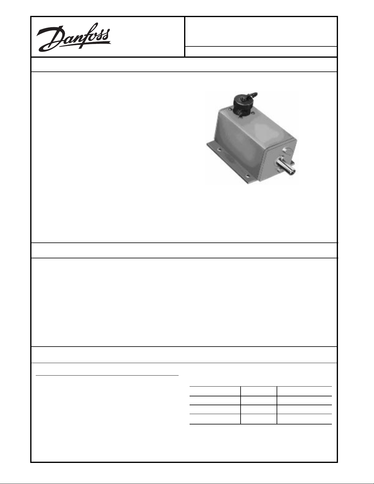
The ACW109D Proportional Rotary Position Controller provides a means of steering a mobile machine. The Controller
senses direction of a wheel or track, compares that direction
to an error signal generated by a remote sensor and supplies
an output for corrective action. In most installations the
ACW109D will occupy the same location assigned to a
feedback transducer in automatic steering control applications.
In a typical application, the ACW109D will obtain direction
informationfromaremotesensorsuchasthe'DQIRVV
ACX104.
The signal will be compared to therotational position of
the Controller input shaft. A pulse widthmodulated
output signal drives an MCV103/113 Flow Control
Servovalve, which moves a cylinder to reposition the
wheels or tracks.
Steering alignment is a common application.
ACW109D
Proportional Rotary Position Controller
BLN-95-8928-4 Issued: March 1992
FEATURES
• Capable of driving a servovalve directly, without additional signal amplification
• Adjustable sensitivity
• Solid state circuitry
• Reverse polarity and short circuit protection
ORDERING INFORMATION
SPECIFY
1. Model Number ACW109D
2. Sensor; ACX104
3. Servovalve; MCV103/113
4. Cables; KW01013, KW01009
• Wiring connections made through MS type connector
• Designed to withstand the vibration associated with mobile equipment
• Can be connected for external bias or remote centering
TABLE A. INFORMATION NECESSARY TO SPECIFY
THE CONTROLLER.
ORDER NUMBER KILOHM POTENTIOMETER
ACW109D1000 10 90°
ACW109D1018 10 342°
ACW109D1026 20 342°
© Danfoss, 2013-09 BLN-95-8928-4 1
Page 2
TECHNICAL DATA
MODELS
Three models are available, dependent upon the mobile
machine’s steering application. See Table B.
TABLE B.
MODEL PROPORTIONAL RATED
1
GAIN TRAVEL
2
ACW109D1000 1.75°±15°
ACW109D1018 7.0°±57°
ACW109D1026 14.0°±114°
Shaft angle change required for full valve
1
drive when set at maximum gain.
Shaft angle change required to match the
2
±3V rated output of the ACX104.
INPUT VOLTAGE
10 to 15 Vdc, 0.5 ampere maximum
OUTPUT VOLTAGE
0 to ±6 Vdc with 12 Vdc supply voltage.
SHAFT ROTATION
The shaft rotates the full 360 angular degrees without
stops.
SHAFT OPERATING TORQUE
No more than 50 inch grams throughout the range of
travel.
NULL POINT
Null point of the Controller is located by a roll pin and
two molded stops on the bearing block. At null, the
longer end of the roll pin is centered between the stops,
and parallel to the case. The short roll pin permits 360°
shaft rotation.
VIBRATION
Withstands a vibration test designed for mobile equipment controllers that includes two parts:
1. Cycling from 5 to 2000 Hz over a range of ±1.5 g’s to
±8.0 g’s for a period of one hour (if there are four
resonant points), for two hours (if there are two or
three resonant points), or for three hours (if there is
one or no resonant point). Cycling test performed on
each of the three major axes.
2. Resonance dwell for one million cycles over a range
of ±1.5 g’s to ±8.0 g’s for each of the four most severe
resonant points on each of the three major axes.
SHOCK
Withstands a shock test designed for mobile equipment
devices that consists of three shocks of 50 g’s and 11
milliseconds duration in both directions of the three
major axes for a total of 18.
OPERATING TEMPERATURE
-18° to +77° C (0° to +170° F)
STORAGE TEMPERATURE
-40° to +77° C (-40° to +170° F)
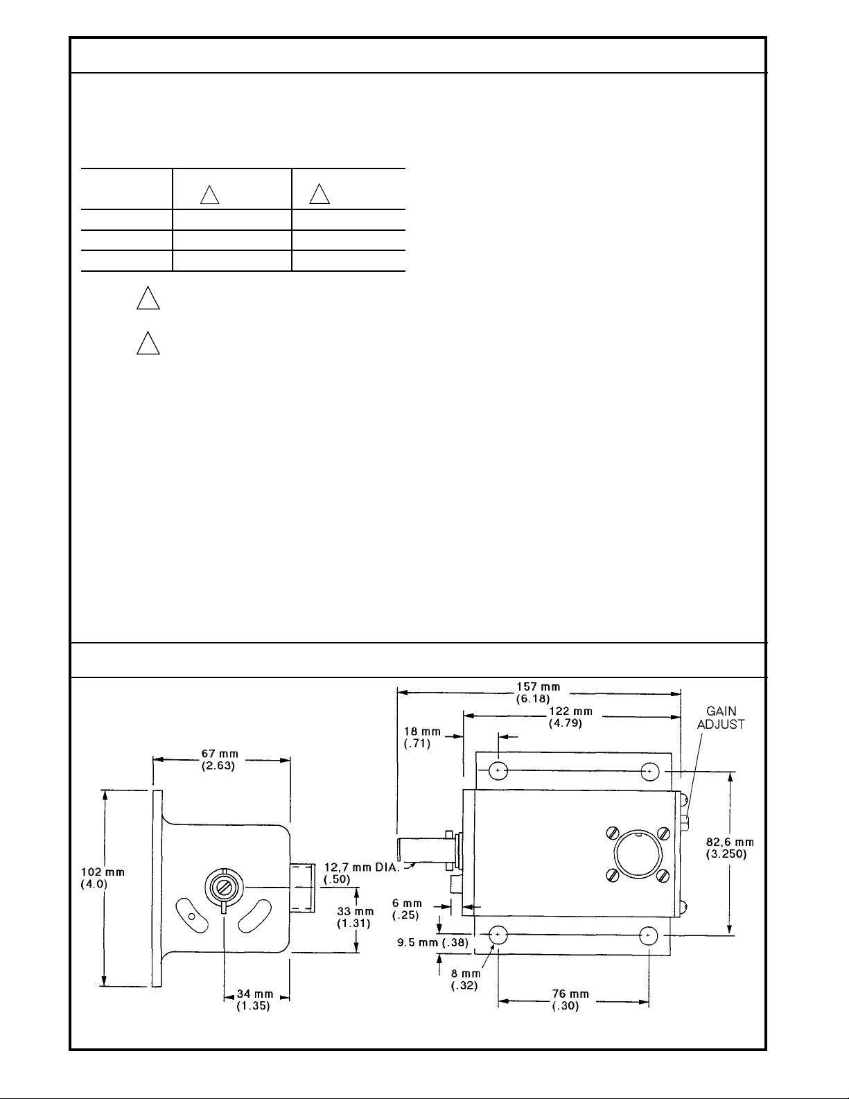
DIMENSIONS
Refer to the Dimensions diagram.
WEIGHT
0.8 kilograms (1 pound, 12 ounces)
DIMENSIONS
BLN-95-8928-4
298C
Mounting Dimensions of the ACW109D in Millimeters (Inches).
2
Page 3
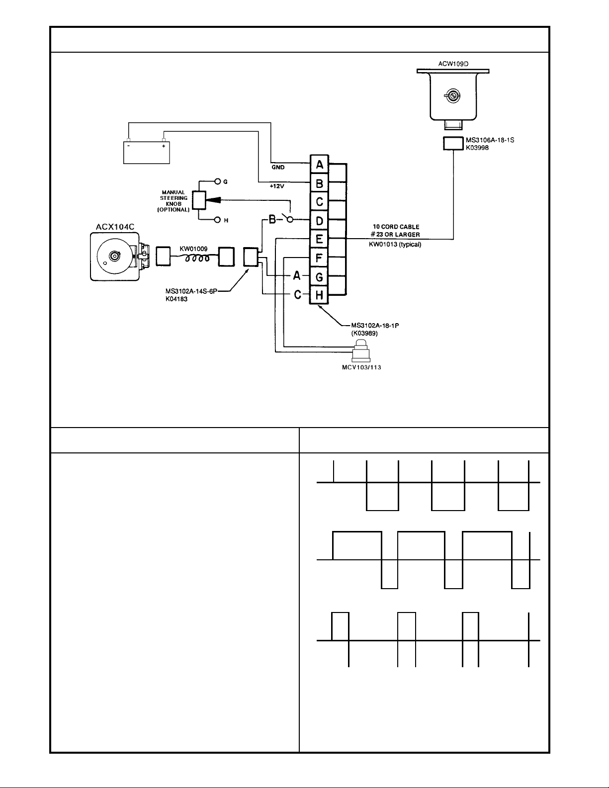
CONNECTION DIAGRAM (Typical)
Wiring Diagram for the ACW109D Used as Electronic Tie Rod.
THEORY OF OPERATION
The output of the ACW109D is a square wave signal used to
operate the MCV103/113 Flow Control Servovalve. This
signal alternately puts a positive 6 Volts on Pin F of the MS
connector, then on Pin E of the connector. See the Typical
Output Signal diagram. Valve control is obtained by increasing the duration of the signal on one pin while decreasing the
duration of the signal on the other.
When at null (neutral) control position, the duration of the 6
Volt output on one pin equals the duration of the 6 Volt output
on the other pin. Because of the frequency of the cycling (250
to 600 Hz), the valve remains centered.
As the shaft is turned clockwise from its null position, the
duration of the signal from Pin F becomes longer and the
duration of the signal from Pin E becomes shorter, the
opposite being true when the shaft is turned counterclockwise.
370D
TYPICAL OUTPUT SIGNAL
F
PULSE RELATION AT NULL
E
F
PULSE DRIVING TOWARD PIN E
E
As the correction in control is made and the steering position
aligns with the sensor, the signals will become balanced and
the servovalve will center.
BLN-95-8928-4
966
3
Page 4

CUSTOMER SERVICE
NORTH AMERICA
ORDER FROM
Danfoss (US) Company
Customer Service Department
3500 Annapolis Lane North
Minneapolis, Minnesota 55447
Phone: (763) 509-2084
Fax: (763) 559-0108
DEVICE REPAIR
For devices in need of repair or evaluation, include a
description of the problem and what work you believe
needs to be done, along with your name, address and
telephone number.
RETURN TO
Danfoss (US) Company
Return Goods Department
3500 Annapolis Lane North
Minneapolis, Minnesota 55447
EUROPE
ORDER FROM
Danfoss (Neumünster) GmbH & Co.
Order Entry Department
Krokamp 35
Postfach 2460
D-24531 Neumünster
Germany
Phone: 49-4321-8710
Fax: 49-4321-871-184
BLN-95-8928-4
4
 Loading...