

Page 1
T
echnical Document
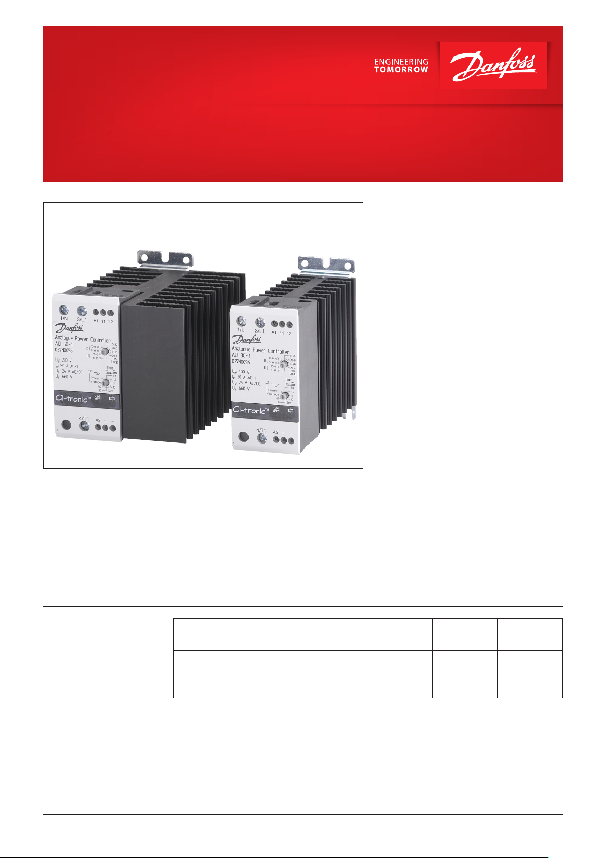
CI-tronic™ Analogue Power Controller
ACI 30-1 and ACI 50-1
Features
• Phase angle or burst ring control mode
• Current loop control, 4 – 20 mA, 20 – 4 mA,
0 – 20 mA and 20 – 0 mA
• Voltage control, 0 – 10 V d.c. and 10 – 0 V d.c.
• Potentiometer control, 0 –10 kΩ and 10 – 0 kΩ
• Rated operational voltage, 230 and 480 V
• Control voltage, 19 – 28 V a.c./d.c.
• DIN-rail mountable
• Built-in varistor protection
• LED status identication
• IP 20 protection
• Compact modular design
• Easy and quick installation
• Specication acc. to industrial standard
• CE, EAC, cULus and LLC CDC TYSK
Description unwanted eects of DC magnetizing on
Selection guide
The versatile ACI analogue power controller is
designed for very precise temperature and
transformer control. Due to the built-in
microprocessor the controller can operate in
phase angle as well as in burst ring control
mode.
The controller automatically adapts to the
load to ensure a smooth inrush, and in burst
ring mode it will further eliminate the
Operational
voltage
V a.c.
208 – 240 30
380 – 480 30 45 ACI 30-1 037N0059
208 – 240 50 90 ACI 50-1 037N0058
380 – 480 50 90 ACI 50-1 037N0060
Operational
current
A
Supply voltage
V a.c. / d.c.
19 – 28
transformers. The ACI unit is easily connected to a
PLC/regulator by means of one of the selectable
input signals.
The analogue controller ACI is typically used as
controller for heaters and infrared lamps but also
ideal on transformer controlled processes.
Dimensions
Type Code no.
mm
45 ACI 30-1 037N0057
© Danfoss | DCS (mw) | 2017.07
IC.PD.C50.C3.02 | 1
Page 2

Technical Document | Analogue power controller, type ACI 30-1 and ACI 50-1
Contents Page
Features ............................................................................................................................................................................. 3
Description ....................................................................................................................................................................... 3
Selection .......................................................................................................................................................................... 3
Technical data ................................................................................................................................................................. 4
Operating at high temperature ................................................................................................................................ 4
Control selection ............................................................................................................................................................ 5
Function mode selection ............................................................................................................................................ 5
Wiring ................................................................................................................................................................................. 5
Applications (heater load) .......................................................................................................................................... 6
Application (transformer load) ................................................................................................................................. 6
Overhead protection .................................................................................................................................................... 7
EMC specication........................................................................................................................................................... 7
Dimensions ...................................................................................................................................................................... 8
Mounting instruction ................................................................................................................................................... 8
© Danfoss | DCS (mw) | 2017.07
IC.PD.C50.C3.02 | 2
Page 3
Technical Document | Analogue power controller, type ACI 30-1 and ACI 50-1
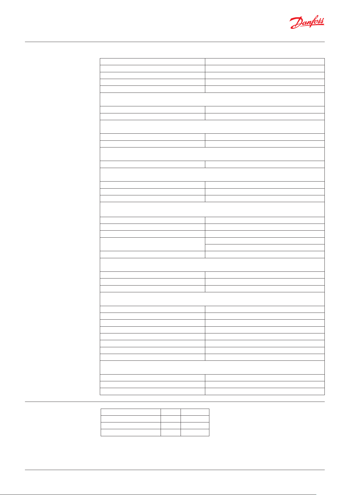
Technical data Output specications
Operational current max. AC-51 (heater load) 30 A 50 A
Operational current max. AC-56a (transformer load 30 A 30 A
Operational voltage 50/60 Hz 230 V / 480 V
Leakage current max. 1 mA
Operational current min. 10 mA
Control method
Phase angle control Selectable linear power or linear voltage
Burst ring control Selectable cycle time : 0.4 – 60 seconds
Semiconductor protection fusing
Type 1 co-ordination 50 A gL/gG
Type 2 co-ordination I2t(t=10 ms) 1800 A2s
Control circuit specications
Control supply voltage 19 – 28 V a.c./d.c.
Control signals
Current loop control (voltage drop < 3 V) 4 – 20 mA, 20 – 4 mA, 0 – 20 mA and 20 – 0 mA
Voltage control (input resistance > 300 kW) 0-10 V d.c. and 10-0 V d.c.
Potentiometer control 0-10 kΩ and 10-0kΩ
Isolation
Control input Floating control input
Voltage line to control 2.5 kV a.c.
Voltage supply to control 500 V a.c.
Protection
EMC immunity Meets requirements of EN 50082-1 and EN 50082-2
Insulation
Rated insulation voltage, Ui 660 V
Rated impulse withstand voltage, Uimp 4 kV
Installation category III
Thermal specication
Power dissipation, continuous duty 1.2 W/A
Power dissipation, intermittent duty 1.2 W/A x duty cycle
Ambient temperature range -5 – +40°C
Cooling method Natural convection
Mounting Vertical (see general mounting instructions)
Max. ambient temperature with limited current 60°C, see derating for high temperatures in chart below
Storage temperature range -20 – +80°C
Protection degree/ pollution degree IP20/ 3
Material
Housing Self exstinguishing PPO UL 94V1
Heatsink Aluminium black anodised
Base Electroplated steel
Supply and control inputs are protected against
overload and over voltage
Operating at high
temperature
© Danfoss | DCS (mw) | 2017.07
Ambient temperature ACI 30 ACI 50
40 °C 30A 50A
50 °C 25 A 40 A
60 °C 20 A 30 A
IC.PD.C50.C3.02 | 3
Page 4

Technical Document | Analogue power controller, type ACI 30-1 and ACI 50-1
Control mode selection
Selection of control signal
The type of control signal, current, voltage or
potentiometer can be selected on the rotary
switch.
Protection
The control input is protected against overload.
If the current exceeds 25 mA, the loop will
switch OFF and the LEDs will indicate failure. The
input will not be damaged if the 24 V supply by
mistake is connected to the signal input. Control
input terminals are marked with + and -. Correct
polarity must be observed. The control input is
oating.
Insulation voltage
Line voltage to control: 2500 V a.c.
Supply to control: 500 V a.c.
Function mode selection Phase angle
Phase angle control is used for control of infrared
lamps or heaters in IR heating applications. Two
dierent operation modes can be selected
Linear voltage: The load voltage varies linearly
with the control signal.
Linear power: The power delivered to the load
varies linearly with the control signal.
Phase angle
Burst ring
Time cycle 0.4 – 60 sec.
Wiring
Burst ring
In burst ring mode full sine waves are supplied
to the load. Consequently DC magnetizing of the
supply transformer is avoided. The number of
sine waves varies linearly with the control signal.
Adjustable cycle times from 400 ms to 60 sec.
24V AC/DC
30 mA max.
© Danfoss | DCS (mw) | 2017.07
IC.PD.C50.C3.02 | 4
Page 5

Technical Document | Analogue power controller, type ACI 30-1 and ACI 50-1
Applications
(heater load)
Single-phase 230 V a.c. (400 V a.c.)
Phase angle and burst ring mode
Max. load at: 230 V 400V
ACI 30-1 6.9 kW 12 kW
ACI 50-1 11.5 kW 20 kW
Three-phase with neutral
Phase angle and burst ring mode
Max. load at: 230 V
3 x ACI 30-1 20.7 kW
3 x ACI 50-1 34.5 kW
Three phase with single-phase
contactor ECI-1 as slave
Only burst ring mode
R: 230 V a.c.
Varistor, min. 20 mm
diameter
Max. load at: 400 V
ACI 30-1 20.7 kW
ACI 50-1 34.5 kW
Application
(transformer loads)
Transformer loads
ACI load driving capability includes transformer
applications which means that low voltage loads
can be controlled via an isolation transformer
without any surge or DC magnetising of the
transformer.
Switching transformers
The problem in transformer switching is the
magnetic circuit. When the transformer is
switched o, (H = 0) the eld (B) remains on a
high level due to the high remanence of modern
transformer core material. At initial turn-on where
the remanence is unknown the ACI will soft start
to avoid the high current surge and at repetitive
turn-on the switch-o polarity is “remembered”
so next turn-on will be in the opposite polraty,
thereby eliminating the high current surge
normally seen in transformer applications. DC
magnetising is eliminated by operating in full
cycle mode only.
Phase angle mode
An initial turn on ACI will soft start the
transformer to the voltage level set by the
analogue input.
Burst ring mode
An initial turn on ACI will soft start the
transformer to full on mode. The controller will
only allow full cycles to be supplied to the
transformer hereby eliminating current surges
and DC saturation of the transformer
© Danfoss | DCS (mw) | 2017.07
IC.PD.C50.C3.02 | 5
Page 6

Technical Document | Analogue power controller, type ACI 30-1 and ACI 50-1
Applications
(transformer loads)
Overhead protection If required the power controller can be protected
against overheating by inserting a thermostat in
the slot on the right-hand side of the controller.
Order: UP 62 thermostat 037N0050
The thermostat is connected in series with the
control circuit of the main contactor. When the
temperature of the heat sink exceeds 100°C the
main contactor will be switched OFF. A manual
reset is necessary to restart this circuit.
EMC specication The power controller ACI is in conformity with the
standard IEC/EN 60947-4-3 AC
Semiconductor Controllers and Contactors for
non motor loads.
Burst ring control mode:
No action necessary
Phase angle control mode:
I <10 A, no action necessary
I >10 A, connect 1uF capacitor from N/L to L1 as
shown above.
© Danfoss | DCS (mw) | 2017.07
IC.PD.C50.C3.02 | 6
Page 7

Technical Document | Analogue power controller, type ACI 30-1 and ACI 50-1
© Danfoss | DCS (mw) | 2017.07
IC.PD.C50.C3.02 | 7
Page 8

Danf
already on order pro
All trademarks in this material are property of the respec
Dimensions
mm (inch)
Mounting instruction The controller is designed for vertical mounting.
If the controller is mounted horizontally, the load
current must be reduced by 50%.
The controller needs no side clearance.
Clearance between two vertical mounted
controlls must be minimum 80 mm (3.15”).
Clearance between controller and top and
bottom walls must be minimum 30 mm (1.2”).
oss can accept no responsibility for possible errors in catalogues, brochures and other printed material. Danfoss reserves the right to alter its products without notice. This also applies to products
vided that such alterations can be made without subsequential changes being necessary eady agreed.
© Danfoss | DCS (mw) | 2017.07
tive companies. Danfoss and the Danfoss logotype are trademarks of Danfoss A/S. All rights reserved.
IC.PD.C50.C3.02 | 8
 Loading...