


Data Sheet
Fan speed controller
Accessory
Type ACCSCS
Electronic controller suitable for fan speed control
ACCSCS are designed to regulate the speed of
fans and pumps proportionally and
continuously. They function as a simple voltage
regulator whose command signal (0..10 V or
4..20 mA or PWM) comes from an external
regulating device.
It’s possible to connect more than one motor in
parallel provided that the maximum input
regulating current is less than the controller
nominal current.
Features:
Three phase model
• Power 400 V
• Input voltage three phase 400 V AC -15 +10%,
50/60 Hz
• Output voltage 30 – 99% of supply line
• Command signal 0 – 10 V, 4 – 20 mA and
PWM 5 / 10 V
• Aux output supply 10 V aux power (Imax = 50
mA) for external potentiometer
• Output relay that commute in case of phase
loss or overtemperature
AI205486421156en-000702
Features
Description
Power supply
400 V AC
Test
According to EN60730 this device provides a type 1 action, it is an incorporated controller suitable for assembly on a at
surface and for use in conditions of normal pollution.
Storage conditions
-20 – 70 °C
Index of protection
Plastic covering which is self-extinguishing: IP55
EMC (Electro-Magnetic Compatibility
The controller has a built-in suppression lter to meet all required CE directives. Danfoss controls are designed to be installed inside a machine or a standard electrical cabinet and is therefore considered a component. It is the installer’s responsibility to observe the criteria of compatibility to guarantee compliance with the directives.
Wiring
• All wiring should conform to local regulations and must be made by authorized personnel only.
• All connections wires must ensure ecient insulation also at temperatures exceeding 80 °C.
• Attach the controller to a non-painted plate with anti-corrosive treatment. If the length of the motor cable exceeds 5 m,
use shielded cable. To avoid dispersion currents, both ends of the motor cable shield, the motor earth, and the
controller earth must be connected to the same earth pole.
• If the control cable length exceeds 2 m, use shielded cable, connecting the shield only at the end of the controller.
• Ensure that the control 0 V is not connected to earth. If the power, motor and control cables exceed 10 m, make sure
they are separated by at least 0.3 m to avoid creating a coupling eect.
• To protect the power line and the regulator, the installation technician must install extra-rapid fuses upstream of the
power supply. If a dierential circuit breaker is installed, it must be of the delayed action type.
Features
Description
Product No.
080G0217
080G0218
080G0219
080G0220
Power - 400 V AC
5.5 K V A
8 K V A
13 K V A
19 K V A
Current nom (Arms)
8 A
12 A
20 A
28 A
Input voltage
Three phase 400 V AC -15 +10%, 50/60 Hz
Output voltage
30 – 99% of supply line
Command signal
Signal 0 – 10 V, 4 – 20 mA, PWM 5/10 V and Modbus
Analog output
10 V (max load 50 mA)
Digital output
Emergency relay 1 A-250 V AC / 3 A-30 V DC
Protections
Class II at the input terminal block (4 K V)
Class I as regards the accessible parts
Phase lost, overheating (the regulator restores automatical)
Operating temperature
-10 – 50 °C (-20 °C when the power is maintained)
Max heat sink tempearture
75 °C
Storage temperature
-20 – 80 °C
Protection degree
Self-extinguishing plastic covering IP55
Dimensions (mm) - LxHxP
230 x 165 x 150
230 x 265 x 165
230 x 265 x 230
340 x 270 x 235
Fan speed controller, Accessory
Product specication
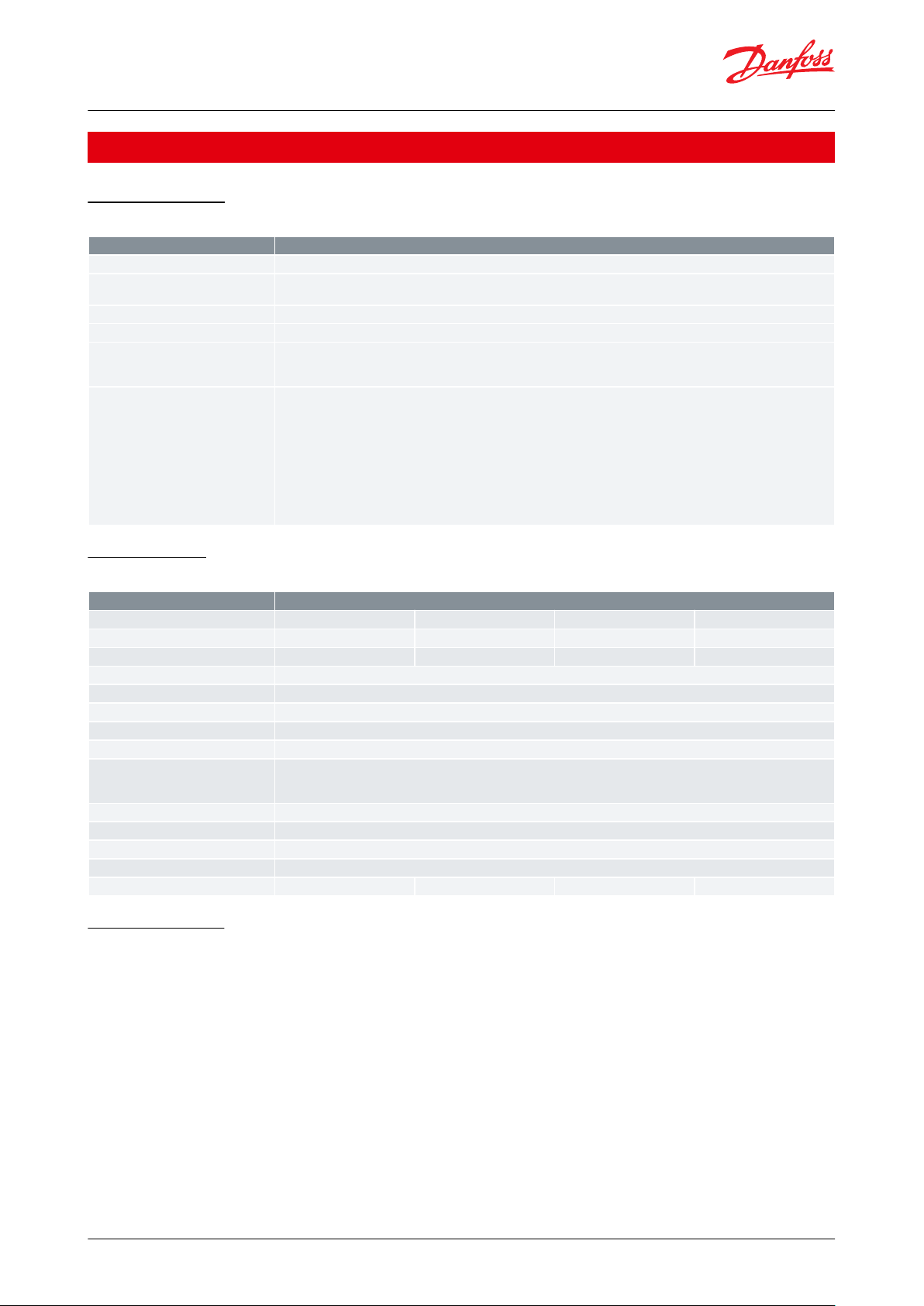
General features
Table 1: General features
Technical data
Table 2: Three phase
Modbus address
Example: Request by the MASTER to read the variable “output voltage” identied with address 0x0B: 01 03 00 0B 00
01.
Request by the MASTER to write on the variable “Modbus input command” identied with address 0x401: 01 06 04 01
00 01.
CAUTION:
The regulation command via Modbus requires rewriting in its address within the time out (default 30 seconds) even
if the value remains unchanged.
Over the time out, in absence of any other command signal, the regulator switch OFF the power outputs.
© Danfoss | Climate Solutions | 2021.03 AI205486421156en-000702 | 2

Vout %
V2
V1
limit V1
IN.MIN IN.MAX 100%
command
1
Danfoss
80G8092A
Vout %
V2
V2
V1
limit V1
IN.MIN IN.MAX 100%
command
2
Danfoss
80G8092B
HEX
address
Variable
Unit
Reading/
Writing
Min. value
Max. value
Description
0x00B
Voltage output
%L–
–
Indicates the output percentage voltage / speed
0x00D
Alarm
NumL–
–
0=no error
1=phase lost
3=over temperature
5=incorrect settings
6=timeout MDB
0x400
Stop regulation
Num
L/S01
Write the value 1 to enable writing and disable the
running place to 0 to re-enable the running
0x421
Regulator address
Num
L/S
(1)
1
247
Indicates the modbus address (slave) - default 0x01
0x422
Baudrate
Num
L/S
(1)
1
3
(=1 if 9600bps)
(=2 if 19200)
(=3 if 38400) - default =2
0x423
Stop Bit
Num
L/S
(1)
1
2
(=1 if 1 stop bit)
(=2 if 2 stop bit) - default=1
0x424
Parity
Num
L/S
(1)
1
3
(=1 if no parity)
(=2 if even parity)
(=3 if odd parity) - default =1
0x425
Timeout
Sec
L/S
(2)
1
240
Indicates the time within which the master must renew his command regulation
0x401
Command by Modbus
%
L/S
(2)
0
100
Variable for command the regulation (0-100) by
Modbus
0x402
Min. input%L/S
(2)
10
Max input
Voltage signal command / speed V1
0x403
Max input%L/S
(2)
Min. input
100
Voltage signal command / speed V2
0x404
Min. V1 voltage
%
L/S
(2)
Lim. min. motor
Max. V2 Voltage
Voltage / speed of IN.MIN. command signal point
0x405
Max. V2 voltage
%
L/S
(2)
Min. V1 voltage
Lim. max. motor
Voltage / speed of IN.MAX. command signal point
0x407
Reset
Num
L/S
(2)
1
3
(=2 to reset and load the controller’s default values)
(=3 to restart the regulator after changing the
parameter / s when is required the reboot)
0x40A
Lim. Speed V1
%
L/S
(2)
Lim. min. motor
V2 limit
Voltage that replaces V1, when V1 LIMIT>V1
0x411
Kick start
Num
L/S
(2)
0
1
(=0 kick start enable)
(=1 kick start able)
0x41E
Regulation prole
Num
L/S
(2)
1
2
(=1 linear prole)
(=2 axial fans prole)
Fan speed controller, Accessory
Table 3: Modbus address
(1)
(1)
Necessary reebot after writing the changes.
Necessary reebot after writing the changes.
(2)
(2)
Writing possible only if the parameter “Adjustment Lock” is set to 1.
Writing possible only if the parameter “Adjustment Lock” is set to 1.
Figure 1: Voltage graph 1
Figure 2: Voltage graph 2
© Danfoss | Climate Solutions | 2021.03 AI205486421156en-000702 | 3
080G0217
080G0218 - 080G0219
080G0220 - 080G0279
Danfoss
80G8094B
T3
T2
T1
PE
L1
L2
L3
DL4
DL5
DL3
DL1
DL2
0.10
+V
NC
COM
NO
+5
IN1
0V
4.20
T+
T-
0V
I4I3I2
I1
0V
motor
power supply
LED
command
Danfoss
80G8094C
T1/U
T2/V
T3/W
PE
L3/T
L2/S
L1/R
I4
I3
I2
I1
0V
T+
T-
0V
IF
IF
motor
power supply
DL5
DL4
LED
commandcommand
DL3
DL1
DL2
LED
0.10
+V
NC
COM
NO
+5
IN1
0V
4.20
Danfoss
80G8094D
L3/T
L3/T
28/40
50
60
PE/
PE/
0.10
+V
NC
COM
NO
+5
IN1
0V
4.20
command
command
power supply
power supply
motor
motor
T+
T-
0V
IF
IF
I4I3I2
I1
0V
T3/W
T3/W
L2/S
L2/S
L1/R
L1/R
T2/V
T2/V
T1/U
T1/U
M6
E10
DL2
DL1
DL3
DL4
DL5
LED
Name
Description
Application
T1 +
Serial RS485, Modbus RTU - slave
Serial connection line to a Master controlled device
T1 -
Serial RS485, Modbus RTU - slave
0 V
Ground I/O
Ground I/O
IF
Pwm input 2..20 kHz (Ri = 500 Ω, 5..24 V)
Variable frequency command input IF (only on request)
IF
0.10
Analog input, type 0 – 10 V (Ri = 40 kΩ)
0 – 10 V analog command input
+ V
Aux. supply output 12 V= (max 30 mA)
External potentiometer supply for manual command
NC
Relay 1 contact output normally closed
Programmable output. With standard setting for Defect, the relay is enabled (NO-COM eachother closed) and is disabled in emergency case
COM
Relay 1 common contact output (1A-250 V~ / 3 A-30 V=)
NO
Relay 1 contact output norm. open
+5 V
Output aux. supply 5 V= (max 15 mA)
/
IN 1
Analog input pwm (5 – 15 V, 100 Hz frequency)
PWM input command with variable average value
0 V
Ground I/O
Ground for analgical input
4.20
Analog input , type 4 – 20 mA (Ri = 100 Ω)
4..20 mA analog command input
Fan speed controller, Accessory
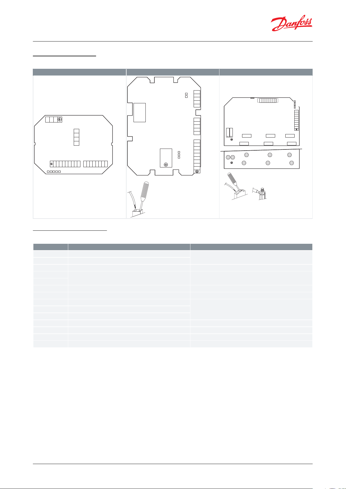
Connection diagram
Table 4: Three phase connection diagram
Controls terminal board
Table 5: Controls terminal board
© Danfoss | Climate Solutions | 2021.03 AI205486421156en-000702 | 4
C
B
D
F
E
F
A
Danfoss
80G8090.01
Code No.
ABCDEFWeight
[mm]
[mm]
[mm]
[mm]
[mm]
[mm]
[kg]
080G0217
230
165
150
21580-
2.5
080G0218
230
265
165
215
170-4
080G0219
230
265
230
215
170-4.8
080G0220
340
270
235
322
165-7
080G0279
230
165
150
21580-
2.5
Fan speed controller, Accessory
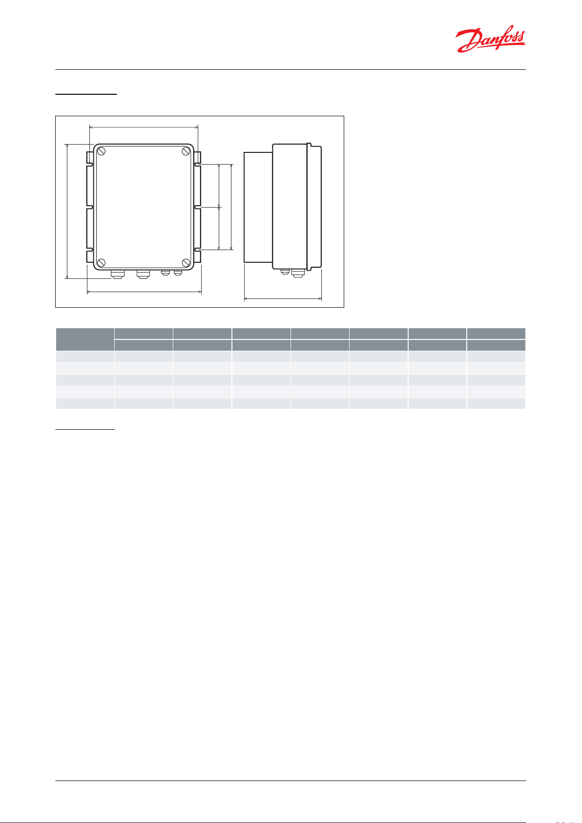
Dimensions
Figure 3: Three phase
Table 6: Dimensions
Installation
Mechanical installation:
The ACCSCS regulator must be wall-mounted vertically, in order to guarantee adequate dispersion of heat in the
area of air circulation and prevent obstructions to air ow in the dissipator zone. ACCSCS has IP55 grade protection,
anyway protect it from corrosive liquids, gas, heat sources and position it preferably sheltered from the sun’s rays.
Make sure that it does not undergo vibrations.
Electrical installation:
All wiring should conform to local regulations and must be made by authorized personnel only. To protect the
power line and the regulator, the installation technician must install extra-rapid semiconductor fuses upstream of
the power supply adequate for the load and with a value of I²xt less than the value given in the table below. If a
dierential circuit breaker is installed, it must be of the delayed action type. The data are related to operate at 400 V
~ 50 Hz. For 230 V voltage supply or models at 440 / 460 V all current data are the same. Max current refers to an
enviroment temperature of 50 °C for a maximum time of 10 second every 5 minutes.
© Danfoss | Climate Solutions | 2021.03 AI205486421156en-000702 | 5

Description
Code No.
ACCSCS, Three Phase Reg. 400 V AC, 8A
080G0217
ACCSCS, Three Phase Reg. 400 V AC, 12A
080G0218
ACCSCS, Three Phase Reg. 400 V AC, 20A
080G0219
ACCSCS, Three Phase Reg. 400 V AC, 28A
080G0220
ACCSCS, Three Phase Reg. 400 V AC, 8A, I
080G0279
Document type
Document topic
EU Declaration of conformity
EMC directive 2014/30/EU
EN61800-3: 2004 +A1: 2012
LVD directive 2015/35/EU:
EN60730-1: 2011
RoHS directive 2011/65/EU and 2015/863/EU:
EN 50581: 2012
Fan speed controller, Accessory
Ordering
Product part numbers
Table 7: Product part numbers
Certicates, declarations, and approvals
The list contains all certicates, declarations, and approvals for this product type. Individual code number may have
some or all of these approvals, and certain local approvals may not appear on the list.
Some approvals may change over time. You can check the most current status at danfoss.com or contact your local
Danfoss representative if you have any questions.
Table 8: Certicates, declarations, and approvals
© Danfoss | Climate Solutions | 2021.03 AI205486421156en-000702 | 6
Online support
Danfoss oers a wide range of support along with our products, including digital product information, software,
mobile apps, and expert guidance. See the possibilities below.
The Danfoss Product Store
The Danfoss Product Store is your one-stop shop for everything product related—no matter where
you are in the world or what area of the cooling industry you work in. Get quick access to essential
information like product specs, code numbers, technical documentation, certications, accessories,
and more.
Start browsing at store.danfoss.com.
Find technical documentation
Find the technical documentation you need to get your project up and running. Get direct access to
our ocial collection of data sheets, certicates and declarations, manuals and guides, 3D models
and drawings, case stories, brochures, and much more.
Start searching now at www.danfoss.com/en/service-and-support/documentation.
Danfoss Learning
Danfoss Learning is a free online learning platform. It features courses and materials specically
designed to help engineers, installers, service technicians, and wholesalers better understand the
products, applications, industry topics, and trends that will help you do your job better.
Create your Danfoss Learning account for free at www.danfoss.com/en/service-and-support/learning.
Get local information and support
Local Danfoss websites are the main sources for help and information about our company and
products. Find product availability, get the latest regional news, or connect with a nearby expert—all
in your own language.
Find your local Danfoss website here: www.danfoss.com/en/choose-region.
Danfoss can accept no responsibility for possible errors in catalogues, brochures and other printed material. Danfoss reserves the right to alter its
products without notice. This also applies to products already on order provided that such alterations can be made without subsequential
changes being necessary in specications already agreed. All trademarks in this material are property of the respective companies. Danfoss and
the Danfoss logotype are trademarks of Danfoss A/S. All rights reserved.
© Danfoss | Climate Solutions | 2021.03 AI205486421156en-000702 | 7
 Loading...