

Page 1

Òu*8Í5P01DÏÓ
INSTRUCTIONS
Accessory for thermal protection of VTZ compressors
To prevent from possible risks of
compressor shell overheating in case of
internal HP/LP by-pass, it’s imperative to
mount the accessory thermal protection
device to the VTZ compressor. The device
must be connected to the frequency
converter which will stop the compressor
at too high shell temperature.
Connection to the CD302 frequency converter:
Wire 1: connector 50
Wire 2: Connector 53 or 54 depending on
availability.
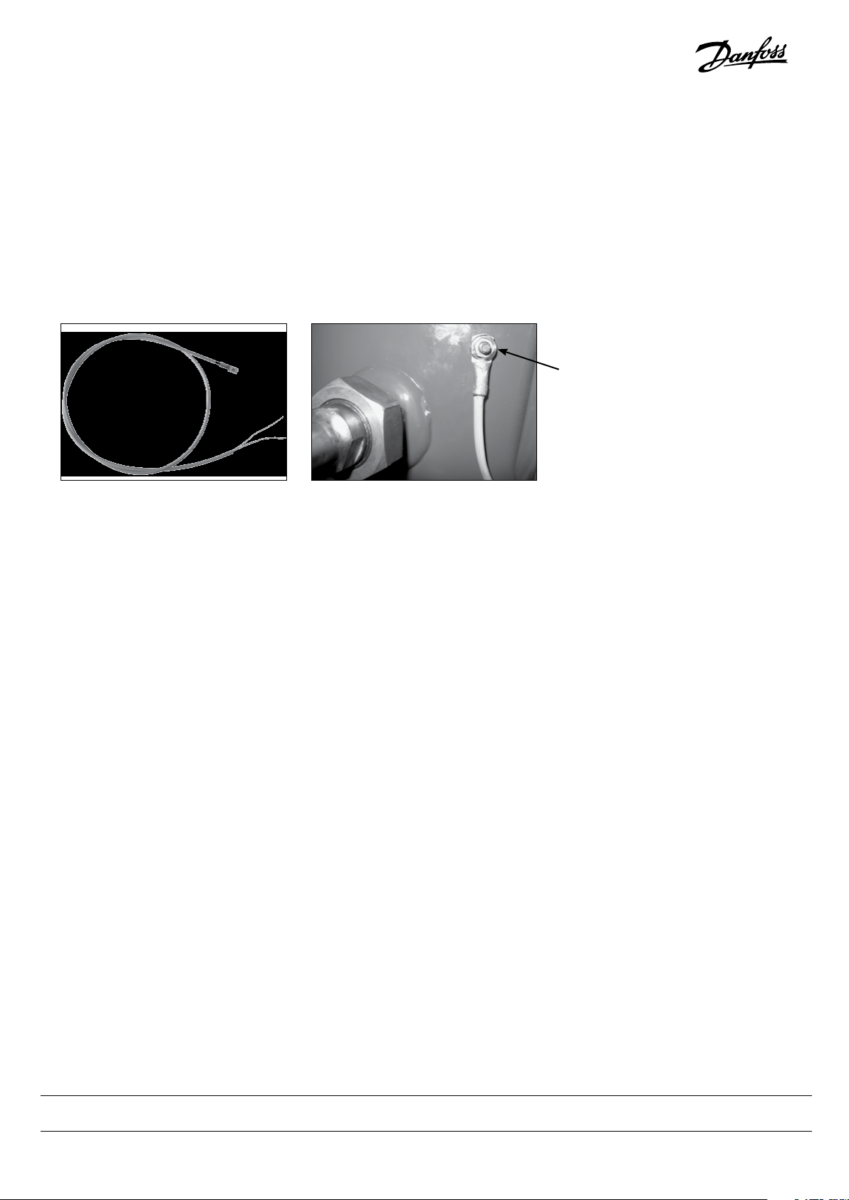
The temperature sensor must be mounted
with the brake washer and the nut on the
stud next to the electrical box as shown in
below picture.
The sensor is a PTC type with an inection
point of 80°C (175°F).
No necessary polarity at the boundaries of
resistance.
The sensor is provided with a cable of 1.1 m
length which can be directly connected to
the CD302 frequency converter. If required
the cable may be extended by a cable with
a minimum cross-section of 2 x 0.25 mm²
(AWG 24).
Recommended torque 1.5N.m
Parameter setting of the CD302 frequency converter:
Push button “Main Menu”
Parameter 1-90 (thermal motor protection) [2] (thermistor trip)
Parameter 1-93 (thermistor source): [1] (input 53) or [2] (input 54) according to the connection of wire 2.
When an abnormally high temperature
is detected by the PTC sensor, the CD302
frequency converter stops the compressor.
The error message “Motor Th Over [A11]”
appears on the the lower line of the LCP
screen and LED “Warn.” blinks.
Every 30 seconds, the CD302 frequency
converter will test for the possibility to
restart the compressor. The number of tests
can be set in Parameter 14-20 (automatic
reset) which is factory pre-set at 10.
Because of the thermal inertia of the total
compressor mass it could happen that
after the maximum number of tests the
temperature is still too high. In such case
the frequency converter will pass in Alarm
mode [A11]. LED “Alarm” blinks. This will
require the intervention of a technician
to carry out a system diagnosis and a new
starting attempt.
Danfoss Commercial Compressors - BP 331 F-01603 Trévoux France - Tel. (33) 4 74 00 28 29 - Fax (33) 4 74 00 52 44 - http://cc.danfoss.com
Danfoss can accept no responsibility for possible errors in catalogues, brochures and other printed material. Danfoss reserves the right to alter its products without notice.
This also applies to products already on order provided that such alterations can be made without sub sequential changes being necessary in specications already agreed.
All trademarks in this material are property of the respective companies. Danfoss and the Danfoss logotype are trademarks of Danfoss A/S. All rights reserved.
FRCC.PI.008.A4.02 October 2013 - 8510245P01D
Danfoss Commercial Compressors - 10/2013
Page 2
Òu*8Í5P01DÏÓ
INSTRUCTIONS
Accessoire de protection thermique compresseur
Pour prévenir les risques éventuels de surchaue des enveloppes de compresseurs,
en cas de bi-pass interne HP / BP, il est impératif de monter une sécurité thermique
reliée au variateur de vitesse qui pilotera
l’arrêt.
Raccordement au variateur :
Fil 1 : borne 50
Fil 2 : borne 53 ou 54 selon disponibilité
Le capteur de température est xé sur le
goujon près du boitier électrique avec une
rondelle frein et un écrou comme représenté sur la photo ci-jointe
Ce capteur est de type PTC avec un point de
d’inexion de résistance variable à 80°C.
Pas de polarité requise aux bornes de la
résistance.
Ce capteur est muni d’un câble de 1.1m
pouvant être directement raccordé au variateur. Il peut être rallongé par un câble de
2 x 0.25mm² minimum (AWG 24)
Couple de serrage 1.5N.m
Paramétrage du variateur :
Utiliser le bouton : « main menu »
Paramètre 1-90 (protection thermique moteur): [2] (thermistor trip)
Paramètre 1-93 (thermistance source) [1] (input 53) ou [2] (input 54) selon disponibilité.
Lorsqu’une température anormale est détectée par la PTC, le variateur de fréquence
arrête le compresseur et le message d’erreur suivant « Motor Th Over » [A11] est
écrit sur la ligne inférieure de l’écran LCP,
LED « Warn. » clignotante.
Le variateur va tester la possibilité de redémarrage toutes les 30 secondes et ceci
X fois en fonction du réglage du Paramètre
: 14-20 (Automatic Reset initialisé à 10 en
paramétrage usine : 20 maxi possible).
En raison de l’inertie due à la masse du
compresseur, le variateur va alors passer en
mode Alarme [A11], LED « Alarm » clignotante, ce qui nécessitera l’intervention d’un
technicien pour eectuer un diagnostic
du système et une nouvelle tentative de
démarrage.
Danfoss Commercial Compressors - BP 331 F-01603 Trévoux France - Tel. (33) 4 74 00 28 29 - Fax (33) 4 74 00 52 44 - http://cc.danfoss.com
Danfoss can accept no responsibility for possible errors in catalogues, brochures and other printed material. Danfoss reserves the right to alter its products without notice.
This also applies to products already on order provided that such alterations can be made without sub sequential changes being necessary in specications already agreed.
All trademarks in this material are property of the respective companies. Danfoss and the Danfoss logotype are trademarks of Danfoss A/S. All rights reserved.
FRCC.PI.008.A4.04 October 2013 - 8510245P01D
Danfoss Commercial Compressors - 10/2013
 Loading...