

Page 1

MAKING MODERN LIVING POSSIBLE
Technical Information
Series 45
G Frame
powersolutions.danfoss.com
Page 2

Technical Information Series 45 G Frame Pumps
Contents
Frame G
Design ........................................................................................................................................................................................... 4
Specifications ............................................................................................................................................................................. 5
Performance G74B .................................................................................................................................................................... 6
Performance G90C ................................................................................................................................................................... 7
Order code ................................................................................................................................................................................... 8
Controls....................................................................................................................................................................................... 10
Pressure compensated control (PC) ........................................................................................................................... 10
Remote PC control (RP) ................................................................................................................................................... 10
Load sensing control (LS) ............................................................................................................................................... 11
Load sensing control with internal bleed orifice (LB) .......................................................................................... 11
Input shafts ............................................................................................................................................................................... 12
Auxiliary mounting pads ...................................................................................................................................................... 13
SAE-A auxiliary mounting pad ..................................................................................................................................... 13
SAE-B auxiliary mounting pad ..................................................................................................................................... 13
Displacement limiter.............................................................................................................................................................. 14
SAE-C auxiliary mounting pad ..................................................................................................................................... 14
Installation drawings ............................................................................................................................................................. 15
Running cover .................................................................................................................................................................... 15
Adjustable displacement limiter ................................................................................................................................. 15
Axial ported endcap ........................................................................................................................................................ 16
Radial ported endcap ...................................................................................................................................................... 18
11058670 • Rev BA • Sep 20132
Page 3

Technical Information Series 45 G Frame Pumps
This information was removed from:
Series 45 Axial Piston Open Circuit Pumps Technical Information Manual 520L0519
Rev E November 2006
For more information regarding the Series 45 product line refer to the current version of 520L0519.
11058670 • Rev BA • Sep 2013 3
Page 4
Technical Information Series 45 G Frame Pumps
T
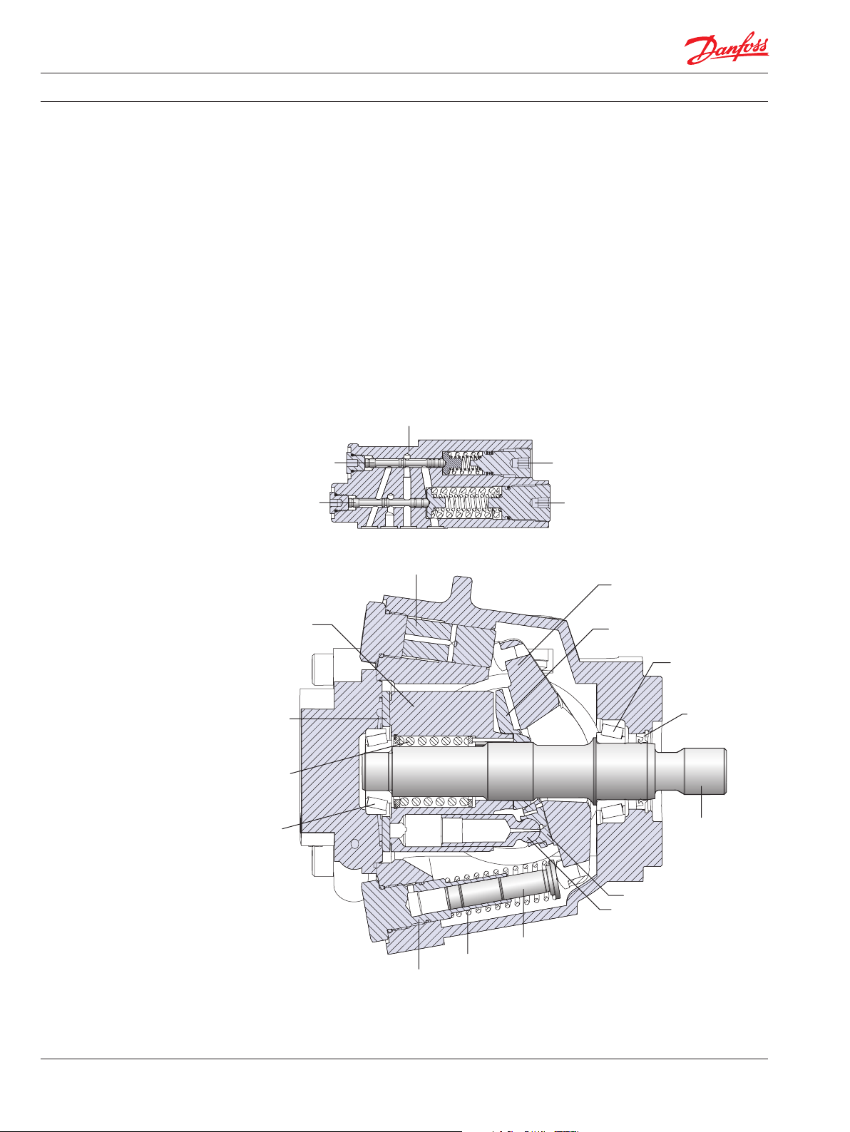
Design
Series 45 Frame G pumps have a dual servo piston design with a cradle-type swashplate set in
polymer-coated journal bearings. The bias piston increases swashplate angle. The displacement
piston decreases swashplate angle. At equal pressure, the larger diameter displacement piston
overpowers the bias piston. Nine reciprocating pistons displace fluid from the pump inlet to the
pump outlet as the cylinder block rotates on the pump input shaft. The block spring holds the piston
slippers to the swashplate via the slipper retainer. The cylinder block rides on a bi-metal valve plate
optimized for high volumetric efficiency and low noise. Tapered roller bearings support the input
shaft and a viton lip-seal protects against shaft leaks.
An adjustable one spool (PC only, not shown) or two spool (LS) control senses system pressure and
load pressure (LS controls). The control ports system pressure to the displacement piston to control
pump output flow.
Frame G cross section
LS control
(attached to endcap)
LS spool
PC spool
LS adjustment
PC adjustment
Displacement piston
Swashplate
Cylinder
block
Valve
plate
Cylinder
block
spring
apered
roller
bearing
Bias piston guide
Bias spring
Bias piston
Slipper retainer
Tapered roller
bearing
Shaft seal
Input shaft
Slipper
Piston
P104 002E
11058670 • Rev BA • Sep 20134
Page 5
Technical Information Series 45 G Frame Pumps
Specifications
For general operating
parameters, including fluid
viscosity, temperature, and
inlet and case pressures,
see page 13. For system design
parameters, including
installation, filtration,
reservoir, and line velocities,
see page 15.
For definitions of pressure and
speed ratings, see page 14. For
more information on external
shaft loads, see page 16;
mounting flange loads,
see page 17.
Features and options
Feature Unit G74B G90C
Maximum Displacement cm³ [in³] 74 [4.52] 90 [5.49]
Flow at rated speed (theoretical) l/min
Input torque at maximum
displacement (theoretical)
Mass moment of inertia of internal
rotating components
Weight Axial ports kg [lb] 29 [63]
Radial ports 36 [80]
Rotation Clockwise, Counterclockwise
Mounting SAE-C
Auxiliary mounting (See page 74 ) SAE-A, SAE-B, SAE-BB, SAE-C
System ports (type) 4-bolt split flange
System ports (location) Axial, Radial
Control types (See page 71) PC, Remote PC, LS, LS with internal bleed
Shafts (See page 73) Splined 14 tooth, 17 tooth
Displacement limiters (See page 75 ) Optional, adjustable
[US gal/min]
N•m/bar
[lbf•in/1000 psi]
kg•m²
[slug•ft²]
Straight Ø 31.75 mm [1.25 in]
177.6
[46.9]
1.178
[719]
0.00630
[0.00465]
Ratings
Rating Units G74B G90C
Input speed
Working pressure continuous bar [psi] 310 [4 495] 260 [3770]
External shaft
loads
Bearing life at 140 bar [2030 psi] B10 hours 41 383 19 847
Mounting flange
load moments
1. Input speeds are valid at 1 bar absolute [0 in Hg vac] inlet pressure. See Inlet p ressure vs. speed charts.
1
minimum min-1 (rpm) 500 500
continuous 2400 2200
maximum 2800 2600
maximum 400 [5800] 350 [5075]
External moment (Me) N•m [lbf•in] 300 [2655]
Thrust in (Tin), out (T
at 210 bar [3045 psi] 9048 4339
at 260 bar [3770 psi] 4062 194 8
at 310 bar [4495 psi] 2101 —
Vibratory (continuous) N•m [lbf•in] 1580 [14 000]
Shock (max) 5650 [50 000]
) N [lbf] 2900 [650]
out
Model
198
[52.3]
1.432
[874]
0.00650
[0.00480]
Model
For more information on noise
levels, see page 19.
Sound levels
dB(A) 210 bar [3045 psi] 260 bar [3770 psi] 310 bar [4495 psi]
Model 1800 mi n-1(rpm) Rated speed 1800 min-1(rpm) Rated speed 1800 min-1(rpm) Rated speed
G74B 75 78 74 76 75 77
C90C 74 76 75 77 — —
2. S ound data was collec ted in a semi-anechoic chamber. Values have b een adjusted (-3 dB) to refle ct anechoic levels.
11058670 • Rev BA • Sep 2013 5
2
Page 6
Technical Information Series 45 G Frame Pumps
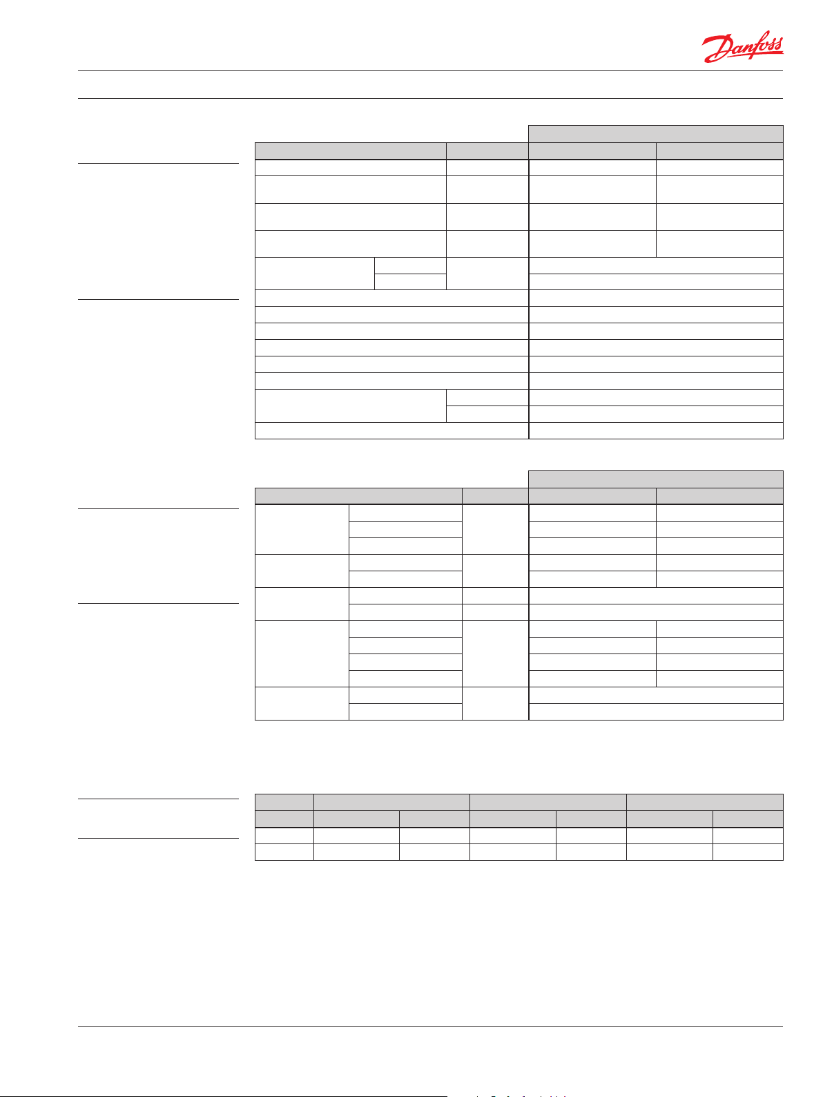
Performance
G74B
Flow and power data valid at
49°C [120°F] and viscosity of
17.8 mm²/sec [88 SUS].
Flow vs. speed
200
160
120
80
Flow (l/min)
40
Input power vs. speed
100
80
60
40
Power (kW)
20
0
0 500 1000 1500 2000 2500
Speed min(rpm)
-1
260 bar [3770 psi]
210 bar [3045 psi]
140 bar [2030 psi]
P104 004E
50
40
30
20
Flow (US gal/min)
10
0
120
100
80
60
Power (hp)
40
20
The chart on the right shows
allowable inlet pressure and
speed at various
displacements. Greater speeds
and lower inlet pressures are
possible at reduced
displacement. Operating
outside of acceptable limits
reduces pump life.
0
Inlet pressure vs. speed
1.6
1.5
1.4
1.3
1.2
1.1
1.0
0.9
0.8
Inlet Pressure (bar abs)
0.7
0.6
0 500 1000 1500 2000 2500
Speed min(rpm)
2000 2200 2400 2600 2800 3000
Shaft Speed min(rpm)
-1
100% 90%80%
-1
P104 005E
P104 015E
0
8
6
4
2
0
3
6
9
(psi gauge)
ac)
(in Hg v
11058670 • Rev BA • Sep 20136
Page 7
Technical Information Series 45 G Frame Pumps
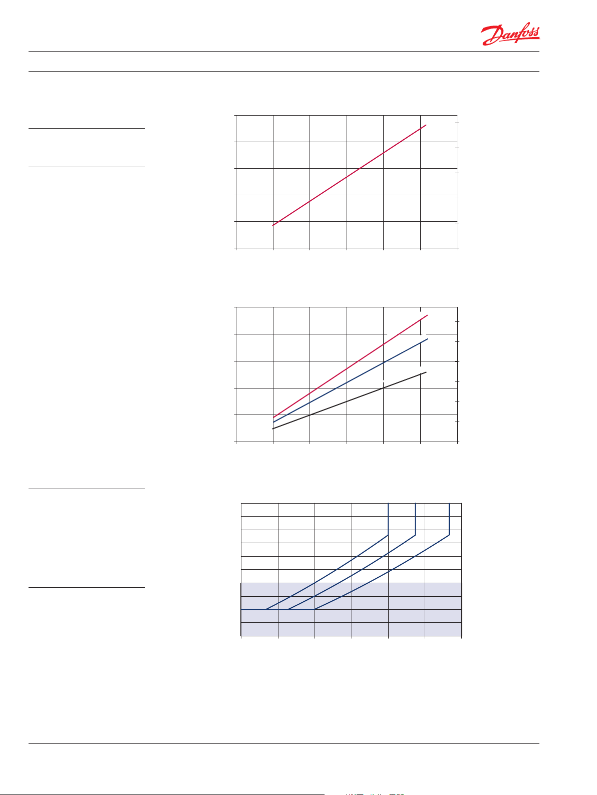
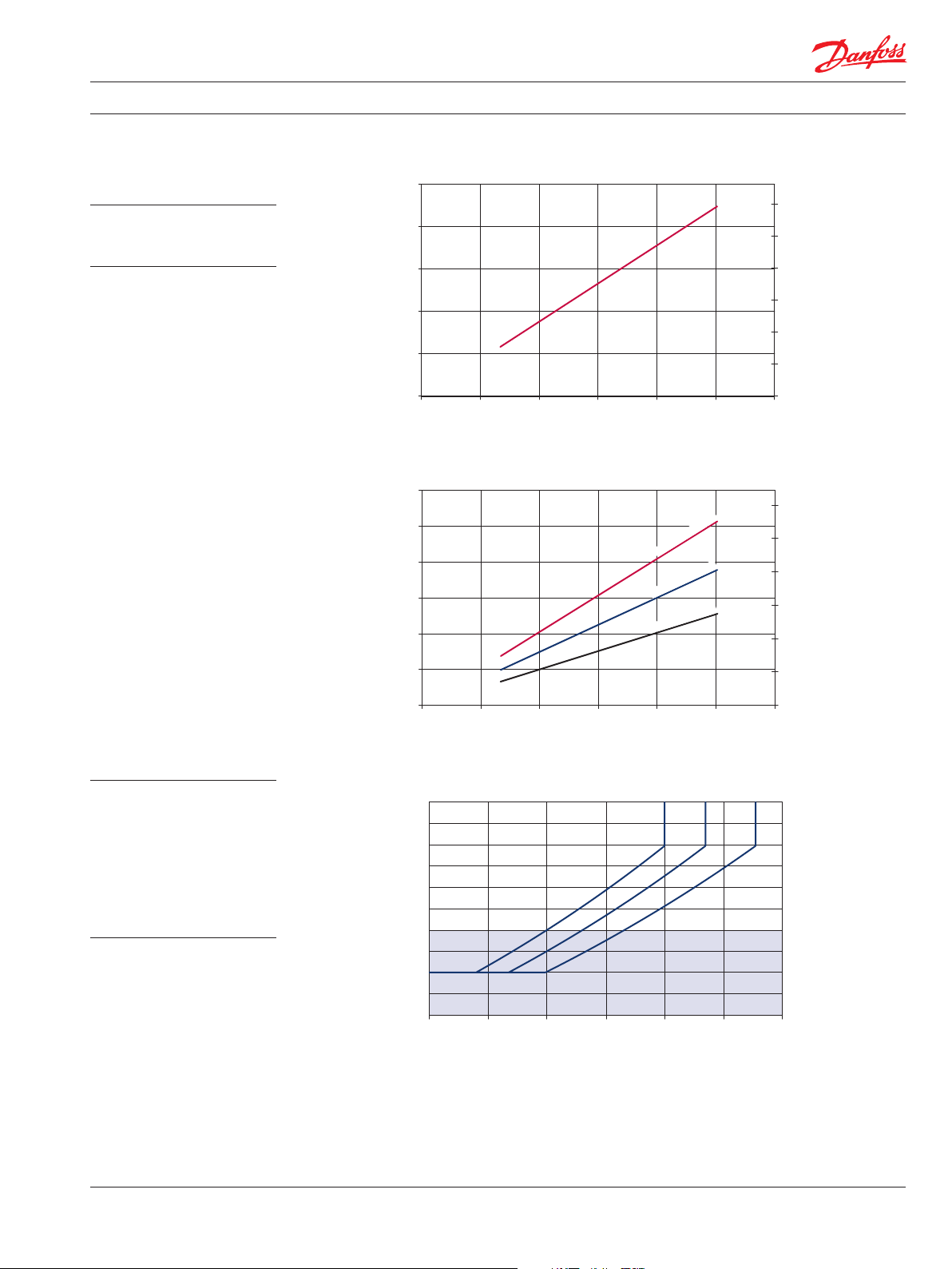
Performance
G90C
Flow and power data valid at
49°C [120°F] and viscosity of
17.8 mm²/sec [88 SUS].
Flow vs. speed
250
200
150
100
Flow (l/min)
50
Input power vs. speed
120
100
80
60
40
Power (kW)
0
0 500 1000 1500 2000 2500
Speed min(rpm)
-1
255 bar [3698
697
[2
bar
186
r [1798 p
a
b
4
12
psi]
psi]
60
50
40
30
20
Flow (US gal/min)
10
0
P104 006E
150
125
100
si]
75
50
Power (hp)
The chart on the right shows
allowable inlet pressure and
speed at various
displacements. Greater speeds
and lower inlet pressures are
possible at reduced
displacement. Operating
outside of acceptable limits
reduces pump life.
20
0
Inlet pressure vs. speed
1.6
1.5
1.4
1.3
1.2
1.1
1.0
0.9
0.8
Inlet Pressure (bar abs)
0.7
0.6
0 500 1000 1500 2000 2500
Speed min(rpm)
1800 2000 2200 2400 2600 2800
Shaft Speed min(rpm)
-1
100% 90%80%
-1
P104 007E
P104 015E
25
0
8
6
4
2
0
3
6
9
(psi gauge)
ac)
(in Hg v
11058670 • Rev BA • Sep 2013 7
Page 8

Technical Information Series 45 G Frame Pumps
Order Code
J K
R S P C D E F G H 1 2 3 1 2 3 L M N
R Product
GR G Frame, variable displacement open circuit pump
S Rotation
L Left hand (counterclockwise)
R Right hand (clockwise)
P Displacement and pressure rating
074B 074 cm³/rev [4.52 in³/rev], 310 bar [4495 psi] continuous working pressure
090C 090 cm³/rev [5.49 in³/rev], 260 bar [3770 psi] continuous working pressure
C Control type
PC Pressure compensated control 100-280 bar [1450-4060 psi]
BC Pressure compensated control 290-310 bar [4205-4495 psi]
RP Remote pressure compensated control 100-280 bar [1450-4060 psi]
BP Remote pressure compensated control 290-310 bar [4205-4495 psi]
LS Load sensing / pressure compensating control 100-280 bar [1450-4060 psi]
BS Load sensing / pressure compensating control 290-310 bar [4205-4495 psi]
LB Load sensing / pressure compensating control with internal bleed orifice 100-280 bar [1450 -4060 psi]
BB Load sensing / pressure compensating control with internal bleed orifice 290 -310 bar [4205-4495 psi]
D PC setting (2 digit code, 10 bar increments)
Example 10 = 100 bar
10–31 100 to 310 bar [1450 to 4495 psi] (074B)
10–26 100 to 260 bar [1450 to 3770 psi] (090C)
E Load sensing setting (2 digit code, 1 bar increments)
Example 20 = 20 bar
10–30 10 to 40 bar [145 to 435 psi]
NN Not applicable (use with PC controls)
F Not used
NN Not applicable
11058670 • Rev BA • Sep 20138
Page 9

Technical Information Series 45 G Frame Pumps
Order Code
(continued)
J K
R S P C D E F G H 1 2 3 1 2 3 L M N
G Pilot orifice
N Standard
H Gain orifice
3 Standard
J1 Input shaft
S1 14 tooth, 12/24 pitch (ANSI B92.1 1970 - Class 5)
S2 17 tooth, 12/24 pitch (ANSI B92.1 1970 - Class 5)
K4 Ø 31.75 mm [1.25 in], straight keyed
J2 Auxiliary mounting flange
N None
A SAE-A, 9-tooth coupling
T SAE-A, 11-tooth coupling
B SAE-B, 13-tooth coupling
V SAE-BB, 15-tooth coupling
C SAE-C, 14-tooth coupling
J3 System port size and location
Code Location Port type Inlet size Outlet size
2 Radial 4-bolt split-flange 2 in. 1 in.
4 Axial 4-bolt split-flange 2 in. 1 in.
K1 Shaft seal
A Single lip seal, viton
K2 Mounting flange and housing port style
1 SAE-C 4-bolt, SAE O-ring boss housing ports
K3 Not used
N Not applicable
L Displacement limiter
NNN None
AAA Adjustable, factory set at max angle (074B)
CAA Adjustable, factory set at max angle (090C)
M Special hardware
NNN None
N Special features
NNN None
11058670 • Rev BA • Sep 2013 9
Page 10

Technical Information Series 45 G Frame Pumps
M2
L2
M4
M2
Controls
Specifications
Schematic diagram
Pressure compensated control (PC)
PC control setting range
Model bar psi
G74B 100 –310 1450–4495
G90C 100 –260 1450–3770
PC schematic
B
L2
L1
S
P104 332
Remote PC control (RP)
Response/recovery times*
(ms) Response Recovery
G74B 35 130
G90C 40 140
* For definitions, see page 9.
Legend
B = Outlet
S = Inlet
L1, L2 = Case drain
M2 = System pressure gauge port
M4 = Servo pressure gauge port
Specifications
Schematic diagram
PC control setting range
Model bar psi
G74B 100 –310 1450–4495
G90C 100 –260 1450–3770
Remote PC schematic
X
B
P104 333
S
L1
X
M4
Response/recovery times*
(ms) Response Recovery
G74B 35 130
G90C 40 140
* For definitions, see page 10.
Legend
B = Outlet
S = Inlet
L1, L2 = Case drain
M2 = System pressure gauge port
M4 = Servo pressure gauge port
X = Remote PC port
11058670 • Rev BA • Sep 201310
Page 11

Technical Information Series 45 G Frame Pumps
M2
SL
M4
M2
M4
Controls (continued) Load sensing control (LS)
Specifications
Schematic diagram
PC setting range
Model bar psi
G74B 100 –310 1450–4495
G90C 100 –260 1450–3770
LS Schematic
X
B
L2
S
P104 331
L1
Response/recovery times*
(ms) Response Recovery
G74B 35 10 0
G90C 40 130
* For definitions, see page 11
LS setting range
Model bar psi
All 10–30 145–435
X
Legend
B = Outlet
S = Inlet
L1, L2 = Case drain
M2 = System pressure gauge port
M4 = Servo pressure gauge port
X = LS signal port
Specifications
Schematic diagram
Load sensing control with internal bleed orifice (LB)
PC setting range
Model bar psi
G74B 100 –310 1450–4495
G90C 100 –260 1450–3770
LB Schematic
X
X
Response/recovery times*
(ms) Response Recovery
G74B 35 10 0
G90C 40 130
* For definitions, see page 11.
LS setting range
Model bar psi
All 10–30 145–435
Legend
B = Outlet
B
S = Inlet
L1, L2 = Case drain
M2 = System pressure gauge port
M4 = Servo pressure gauge port
X = LS signal port
L2
P104 330
1
11058670 • Rev BA • Sep 2013 11
Page 12

Technical Information Series 45 G Frame Pumps
[1.89 ± 0.024]
[0.31
Mounting
flange
P104 034E
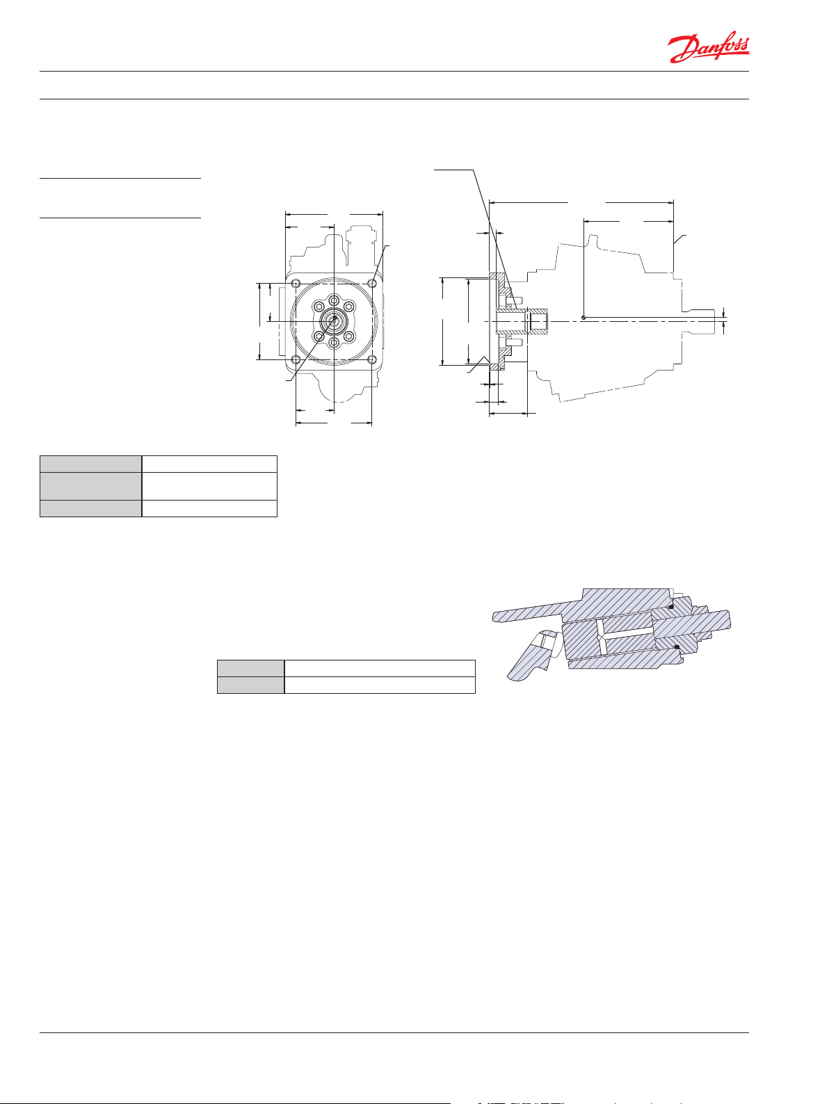
Input Shafts
Shaft data
Code Description
S1 14 tooth spline
12/24 pitch
(ANSI B92.1 1970 - Class 5)
Maximum torque rating¹
N•m [lbf•in] Drawing
734 [6500]
47.6 ± 0.6
[1.84 ± 0.024]
25.52 [1.005] max
Mounting
flange
8 ± 0.8
[0.31 ± 0.03]
29.634 [1.167] pitch |
14 teeth 12/24 pitch
30` pressure angle
fillet root side fit
Compatible with
ANSI b92.1-1970
Class 5 also mates with
flat root side fit
Ø28 ± 0.15
[1.102 ± 0.006]
Coupling must not
protrude beyond
this point
Ø31.14 ± 0.08
[1.226 ± 0.003]
P104 032E
S2 17 tooth spline
12/24 pitch
(ANSI B92.1 1970 - Class 5)
K4 Ø 31.75 mm [1.25 in]
Straight keyed
1017 [9000]
734 [6495]
53.97 ± 0.6
[1.874 ± 0.024]
30.75 max
[1.211]
Mounting
flange
48.06 ± 0.6
8 ± 0.8
± 0.03]
8 ± 0.8
[0.31 ± 0.03]
Coupling must not
protrude beyond
this point
A
A
Ø31.72
[1.249 ± 0.001]
Coupling must not
protrude beyond
this point
+0
7.94
-0.05
+0
[0.313 ]
-.002
Sq. Key x 28.56 lg
Section A-a
± 0.02
35.983 [1.417] pitch
17 teeth 12/24 pitch
30` pressure angle
fillet root side fit
compatible with
ANSI b92.1-1970
Class 5 also mates with
flat root side fit
Ø36.66 ± 0.08
[1.443 ± 0.003]
Ø34 ± 0.15
[1.339 ± 0.006]
P104 033E
[1.125]
35.2 ± 0.13
±0.01]
[1.39
1. See Input shaf t torque ratings, page 18 for an explanation of maximum torque.
11058670 • Rev BA • Sep 201312
Page 13

Technical Information Series 45 G Frame Pumps
Auxiliary Mounting Pads
SAE-A auxiliary mounting pad
Dimensions
See page 18 for mating pump
pilot and spline dimensions.
106.4
[4.19]
53.2
[2.09]
Coupling-sae 11t:
11 tooth spline, 16/32 pitch
17.463 [0.6875] pitch ø
Fillet root side fit
Per ANSI b92.1-1970, Class 6
Coupling-sae:
9 tooth spline, 16/32 pitch
14.288 [0.5625] pitch ø
Fillet root side fit
Per ANSI b92.1-1970, Class 6
Approximate
Center of
Gravity
O-ring seal required
Ref 82.27 [3.239] i.D.
2.62 [0.103] cross section
3/8 -16 unc-2b THD
17.8 [0.70] min THD depth
2x
Specifications
Coupling 9-tooth 11 -tooth
Spline minimum
engagement
Maximum torque 107 N•m [950 lbf•in] 147 N•m [1300 lbf•in]
Dimension A 21.1 mm [0.83 in] 16.1 mm [0.63 in]
13.5 mm [0.53 in] 15 mm [0.59 in]
Ø88.6
[3.49]
Ø82.6
[3.252
+0.08-0.00
+0.003-0.000
1.9
[0.077]
278.07
[10.95]
A
Min coupling
Clearance
132
[5.2]
Mounting
Flange
[0.24]
6
]
58.5
[2.30]
P104 042E
SAE-B auxiliary mounting pad
Dimensions
87
[3.43]
174
[6.85]
146
[5.75]
73
[2.87]
Coupling-sae b-b:
15 tooth spline, 16/32 pitch
23.813 [0.9375] pitch ø
Fillet root side fit
per ANSI b92.1-1970, class 6
Coupling-sae b:
13 tooth spline, 16/32 pitch
20.638 [0.8125] pitch
Fillet root side fit
per ANSI b92.1-1970, Class 6
1/2-13 unc-2b
Thd thru
19.7 [0.76] min
the depth
2x
Approximate
center of
gravity
See page 18 for mating pump
pilot and spline dimensions.
Specifications
Coupling 13- tooth 15- tooth
Spline minimum
engagement
Maximum torque 249 N•m [2200 lbf•in] 339 N•m [3000 lbf•in]
Dimension A 20.7 mm [0.81 in] 12.7 mm [0.5 in]
14.2 mm [0.56 in] 18.9 mm [0.74 in]
Ø105.64
[4.16]
Ø101.65
[4.002
O-ring seal required
Ref 101.32 [3.989] i.D.
1.78 [0.07] cross section
11±0.13
[0.43±0.01]
1.3
[0.05]
+0.08-0.0
+0.003-0.00
]
A
min coupling
clearance
54.1
[2.13]
273.69
[10.78]
132
[5.20]
Mounting
flange
[0.24]
P104 071E
6
11058670 • Rev BA • Sep 2013 13
Page 14
Technical Information Series 45 G Frame Pumps
Auxiliary Mounting Pads
(continued)
SAE-C auxiliary mounting pad
Dimensions
See page 18 for mating pump
pilot and spline dimensions.
Specifications
Coupling 14-tooth
Spline minimum
engagement
Maximum torque 339 N•m [3000 lbf•in]
18.3 mm [0.72 in]
57.3
[2.26]
114.6
[4.51]
Approximate
center of
gravity
73.25
[2.88]
57.3
[2.26]
Coupling-SAE C:
14 tooth spline, 16/32 pitch
29.633 (1.1667) pitch ø
Flat root side fit
Per ANSI B92.1-1970, Class 6
146.5
[5.77]
114.6
[4.51]
1/2 -13 UNC-2b THD thru
22.7 [0.89] min thd depth
4x
Ø131.57
[5.18]
Ø127.03
[5.001 ]
O-ring seal required
Ref 120.37 [4.379] i.D.
1.78 [0.07] cross section
14 ± 0.13
[0.551 ±0.005]
+.002
0
+0.05
0
10.09
[0.4]
Min coupling
clearance
1.3
[0.051]
Ø57.1
[2.25]
Min shaft
clearance
276.69
[10.89]
135
[5.31]
Mounting
flange
P104 072E
[0.24]
6
Displacement limiter G Frame open circuit pumps are available with an
optional adjustable displacement limiter. This
adjustable stop limits the pump’s maximum
displacement.
Setting range
G74B 56 to 74 cm³ [3.39 to 4.52 in³]
G90C 68 to 90 cm³ [4.12 to 5.49 in³]
Displacement limiter cross-section
P104 026
1. See Input shaf t torque ratings, page 19 for definitions of continuous and maximum torque.
11058670 • Rev BA • Sep 201314
Page 15

Technical Information Series 45 G Frame Pumps
Installation Drawings Running cover
Dimensions
Approximate
center of
gravity
264.2
[10.4]
128
[5.04]
Mounting
flange
6
[0.24]
Adjustable displacement limiter
Dimensions
208.74 MAX
[8.218]
P106 078E
102.84
[4.05]
P104 073E
11058670 • Rev BA • Sep 2013 15
Page 16
Technical Information Series 45 G Frame Pumps
Third-angle
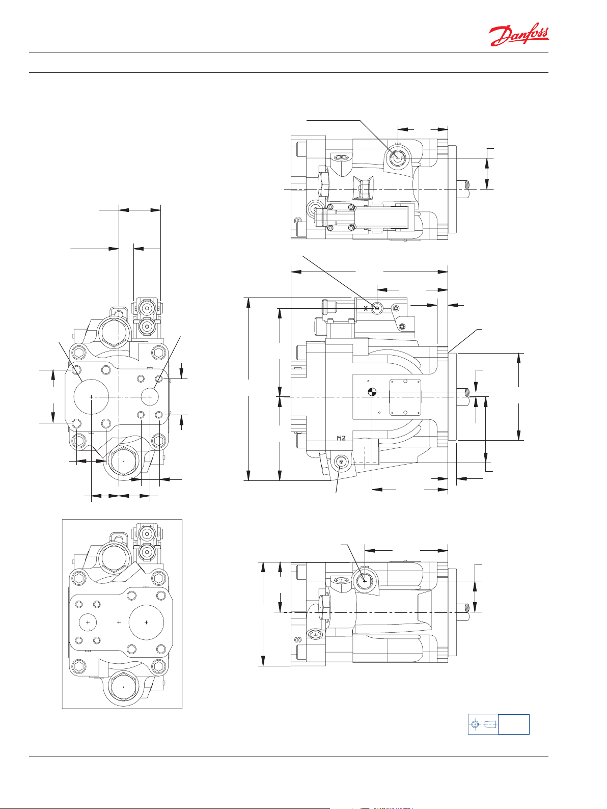
Installation Drawings
(continued)
60.7
[2.39]
21.3
[0.84]
LS signal
Port X
alternate
Ø50.8 [2]
System port S
(Inlet port)
207 Bar [3000 PSI]
Split flange boss
Per ISO 6162
SAE J518
(CODE 61)
with 1/2-13 UNC
x 27 [1.063]
Min THD
77.77
[3.062]
LS signal
Port X
Axial ported endcap
Ø25.4 [1]
System port B
(Outlet port)
345 Bar [3000 PSI]
Split flange boss
Per ISO 6162
SAE J518
(CODE 61)
with 3/8-16 UNC
x 27 [0.866]
Min THD
52.37
[2.062]
Case drain port L1
Per ISO 11926-1
SAE J1926/1
7/8 -14
LS signal porT X
Per ISO 11926-1
SAE J1926/1
7/16 -20 UNF
128.5
[5.06]
265.76
[10.463]
System ports S and B
227.74
[8.97]
102.84
[4.05]
72.74
[2.86]
15.64 4X
[0.62]
45
[1.77]
R1 MAX
[0.04]
7
[0.28]
Ø126.975 ± 0.025
[4.999 ± 0.001]
42.88
[1.688]
40
[1.57]
Clockwise rotation
Counterclockwise rotation
45
[1.77]
26.19
[1.031]
121.76
[4.79]
System pressure gage port M2
Per ISO 11926-1
SAE J1926/1
7/16 -20 UNF
Case drain port L2
Per ISO 11926-1
SAE J1926/1
7/8 -14
73
[2.87]
151
[5.94]
110
[4.33]
120.74
[4.75]
12.7
[0.5]
45
[1.77]
96
[3.78]
Case drain
Port L2
P106 174E
projection
mm [in]
11058670 • Rev BA • Sep 201316
Page 17

Technical Information Series 45 G Frame Pumps
Third-angle
Axial ported endcap (continued)Installation Drawings
(continued)
LS standby
Pressure adjustment
Pc pressure
adjustment
Ø14.3
[0.56]
Approximate
center of
gravity
114.5
[4.51]
CcwCw
57.25
[2.25]
Ls signal port x
Alternate
Per ISO 11926-1
SAE J1926/1
7/16 -20 UNF
128.5
[5.06]
96
[3.78]
Case drain
port L1
102.84
[4.05]
Servo pressure gage port M4
Per ISO 11926-1
SAE J1926/1
7/16 -20 UNF
57.25
[2.25]
114.5
[4.51]
P104 074e
projection
mm [in]
11058670 • Rev BA • Sep 2013 17
Page 18

Technical Information Series 45 G Frame Pumps
Third-angle
72.74
[2.95]
[3.23]
Installation Drawings
(continued)
60.7
[2.39]
LS SIGNAL
PORT X
21.3
[0.84]
LS SIGNAL
PORT X
ALTERNATE
SYSTEM
PORT S
(inlet)
Radial ported endcap
LS signal port X
Per ISO 11926-1
SAE J1926/1
7/16 -20 UNF
System
Port B
(outlet)
265.76
[10.463]
128.5
[5.06]
Case drain port L1
Per ISO 11926-1
SAE J1926/1
7/8 -14
256.04
[10.08]
212.74
[8.38]
102.84
[4.05]
[2.86]
15.64 4X
[0.62]
[0.24]
45
[1.77]
R1 MAX
[0.04]
6
Ø126.975 ± 0.025
[4.999 ± 0.001]
System
Port B
(outlet)
82
[3.23]
75
[2.95]
Clockwise rotation
75
82
Counterclockwise rotation
System
Port S
(inlet)
Ø25.4 [1]
System port B
(outlet port)
345 Bar [5000 PSI]
Split flange boss
Per ISO 6162
SAE J518
(CODE 61)
with 3/8-16 UNC
x 27 [0.866]
MIN THD
Outlet
121.76
75
[2.95]
82
[3.23]
Inlet
[4.79]
Case drain porT L2
Per ISO 11926-1
SAE J1926/1
7/8 -14
124
[4.88]
System pressure gage port M2
Per ISO 11926-1
SAE J1926/1
7/16 -20 UNF
120.74
[4.75]
12.7
[0.5]
45
[1.77]
96
[3.78]
Case drain
Port L2
P106 175E
projection
mm [in]
11058670 • Rev BA • Sep 201318
Page 19

Technical Information Series 45 G Frame Pumps
Servo pressure gage port M4
Third-angle
Installation Drawings
(continued)
PC pressure
Adjustment
Approximate
center of
gravity
57.25
[2.25]
Radial ported endcap (continued)
LS standby
Pressure adjustment
Ø14.3
[0.56]
114.5
[4.51]
CCWCW
57.25
[2.25]
114.5
[4.51]
LS signal port X
Alternate
Per ISO 11926-1
SAE J1926/1
7/16 -20 UNF
128.5
[5.06]
96
[3.78]
Case drain
port L1
102.84
[4.05]
215.74
[8.49]
Per ISO 11926-1
SAE J1926/1
7/16 -20 UNF
Ø50.8 [2]
System port S
(Inlet port)
207 Bar [3000 PSI]
Split flange boss
Per ISO 6162
SAE J518
(Code 61)
with 1/2-13 UNC
x 27 [1.063]
MIN THD
P104 075E
projection
mm [in]
11058670 • Rev BA • Sep 2013 19
Page 20

Products we off er:
Bent Axis Motors
Closed Circuit Axial Piston
Pumps and Motors
Displays
Electrohydraulic Power
Steering
Electrohydraulics
Hydraulic Power Steering
Integrated Systems
Joysticks and Control
Handles
Microcontrollers and
Software
Open Circuit Axial Piston
Pumps
Orbital Motors
P LUS+1® GUIDE
Proportional Valves
Sensors
Steering
Transit Mixer Drives
Danfoss Power Solutions is a global manufacturer and supplier of high-quality hydraulic and
electronic components. We specialize in providing state-of-the-art technology and solutions that
excel in the harsh operating conditions of the mobile off -highway market. Building on our extensive
applications expertise, we work closely with our customers to ensure exceptional performance for a
broad range of off -highway vehicles.
We help OEMs around the world speed up system development, reduce costs and bring vehicles to
market faster.
Danfoss – Your Strongest Partner in Mobile Hydraulics.
Go to www.powersolutions.danfoss.com for further product information.
Wherever off -highway vehicles are at work, so is Danfoss.
We off er expert worldwide support for our customers, ensuring the best possible solutions for
outstanding performance. And with an extensive network of Global Service Partners, we also provide
comprehensive global service for all of our components.
Please contact the Danfoss Power Solution representative nearest you.
Comatrol
www.comatrol.com
Schwarzmüller-Inverter
www.schwarzmueller-
Local address:
inverter.com
Turolla
www.turollaocg.com
Valmova
www.valmova.com
Hydro-Gear
www.hydro-gear.com
Daikin-Sauer-Danfoss
www.daikin-sauer-danfoss.com
Danfoss
Power Solutions US Company
2800 East 13th Street
Ames, IA 50010, USA
Phone: +1 515 239 6000
Danfoss can accept no responsibility for possible errors in catalogues, brochures and other printed material. Danfoss reserves the right to alter its products without notice. This also applies to products
already on order provided that such alterations can be made without subsequential changes being necessary in specifications already agreed.
All trademarks in this material are property of the respective companies. Danfoss and the Danfoss logotype are trademarks of Danfoss A/S. All rights reserved.
11058670 • Rev BA • Sep 2013 www.danfoss.com © Danfoss A/S, 2013-09
Danfoss
Power Solutions GmbH & Co. OHG
Krokamp 35
D-24539 Neumünster, Germany
Phone: +49 4321 871 0
Danfoss
Power Solutions ApS
Nordborgvej 81
DK-6430 Nordborg, Denmark
Phone: +45 7488 2222
Danfoss
Power Solutions
22F, Block C, Yishan Rd
Shanghai 200233, China
Phone: +86 21 3418 5200
 Loading...