

Page 1
Technical Information
Series 42 4T Axial Piston Tandem Pumps
Size 41/51
www.danfoss.com
Page 2
Technical Information
Series 42 4T Axial Piston Tandem Pumps Size 41/51
Revision history Table of revisions
Date Changed Rev
November 2020 Minor update in Hydraulic Fluid Parameters 0302
July 2020 Changed document number from 'BC00000036' to 'BC152886482857' 0301
December 2018 Corrected technical data in System Parameters 0201
June 2016 converted to new layout 0101
May 2015 Converted to DITA CMS BA
February 2008 Corrections-Drawings AB
January 2008 First edition AA
2 | © Danfoss | November 2020 BC152886482857en-000302
Page 3

Technical Information
Series 42 4T Axial Piston Tandem Pumps Size 41/51
Contents
Series 42 warehouse
General Description
Basic Design........................................................................................................................................................................................6
System Diagram................................................................................................................................................................................7
System Schematic............................................................................................................................................................................ 8
Technical Specifications
System Specifications...................................................................................................................................................................10
System Parameters........................................................................................................................................................................10
Hydraulic Fluid Parameters........................................................................................................................................................ 11
Operating Parameters
System Requirements...................................................................................................................................................................12
System Parameters........................................................................................................................................................................12
Hydraulic Fluid Parameters........................................................................................................................................................ 13
Sizing Equations............................................................................................................................................................................. 14
System Design Parameters
Fluid and Filtration........................................................................................................................................................................ 15
Filtration Configuration...............................................................................................................................................................15
Mounting Flange Loads...............................................................................................................................................................16
Estimating Overhung Load Moment.................................................................................................................................16
Case Drain.........................................................................................................................................................................................17
External Shaft Load and Bearing Life......................................................................................................................................17
Hydraulic Unit Life......................................................................................................................................................................... 18
Efficiency Graphs............................................................................................................................................................................19
Features and Options
Charge Pump...................................................................................................................................................................................20
Charge Pump Sizing Example:.............................................................................................................................................20
Charge Relief Valve........................................................................................................................................................................20
Overpressure Protection............................................................................................................................................................. 21
Bypass Valve.....................................................................................................................................................................................22
Displacement Limiters................................................................................................................................................................. 22
Shaft Options...................................................................................................................................................................................22
Auxiliary Mounting Pads............................................................................................................................................................. 23
Center Coupling............................................................................................................................................................................. 24
Control Selection............................................................................................................................................................................24
Manual Displacement Control (MDC).....................................................................................................................................26
Features and Benefit of MDC................................................................................................................................................26
Control Input Signal.................................................................................................................................................................27
Response Time...........................................................................................................................................................................27
Control Handles.........................................................................................................................................................................28
Electric Solenoid Override to Neutral................................................................................................................................28
Emergency Override to Neutral with Port for Brake Pressure Release..................................................................29
Neutral Start Switch (NSS)..................................................................................................................................................... 30
NSS with Back-up Alarm (BUA) Switch..............................................................................................................................30
Connectors..................................................................................................................................................................................30
Non-Feedback, Proportional Hydraulic (NFPH) Control.................................................................................................. 32
Features and Benefits of the NFPH control..................................................................................................................... 33
Connectors and Port locations............................................................................................................................................ 33
Installation Drawings
Manual Displacement Control (MDC).....................................................................................................................................34
Port Description........................................................................................................................................................................ 34
Dimensions................................................................................................................................................................................. 36
Non-Feedback, Proportional Hydraulic (NFPH).................................................................................................................. 39
Port Description........................................................................................................................................................................ 39
Dimensions................................................................................................................................................................................. 41
Shaft Options...................................................................................................................................................................................44
Displacement Limiter................................................................................................................................................................... 45
©
Danfoss | November 2020 BC152886482857en-000302 | 3
Page 4

Technical Information
Series 42 4T Axial Piston Tandem Pumps Size 41/51
Contents
By-pass Valve...................................................................................................................................................................................46
Control Modules.............................................................................................................................................................................46
Auxiliary Mounting Pads............................................................................................................................................................. 48
Model Code
Model Code: A, Y, Z........................................................................................................................................................................50
Model Code: FD, FX, RD, RX........................................................................................................................................................51
Model Code: FE, RE........................................................................................................................................................................ 52
Model Code: FT, RT, FH, RH, FJ, RJ, FK, RK..............................................................................................................................53
Model Code: FL, RL, FM. RM........................................................................................................................................................54
Model Code: C, F, S........................................................................................................................................................................ 56
Model Code: U, G, V.......................................................................................................................................................................57
Model Code: N, P............................................................................................................................................................................58
4 | © Danfoss | November 2020 BC152886482857en-000302
Page 5
Piston centering spring
Servo piston
P100412E
P400169
M4
M5
L2
X2 X1
D
i
s
p
l
a
c
e
m
e
n
t
100%
100%
15 18
6
6
1518
P001628E
Signal Dp (bar)
Dp system=345bar
Dp system=345bar
Dp system=35bar
Dp system=35bar
Technical Information
Series 42 4T Axial Piston Tandem Pumps Size 41/51
Series 42 warehouse
Series 42 warehouse
Pump displacement versus signal pressure
NFPH pump displacement to Input signal
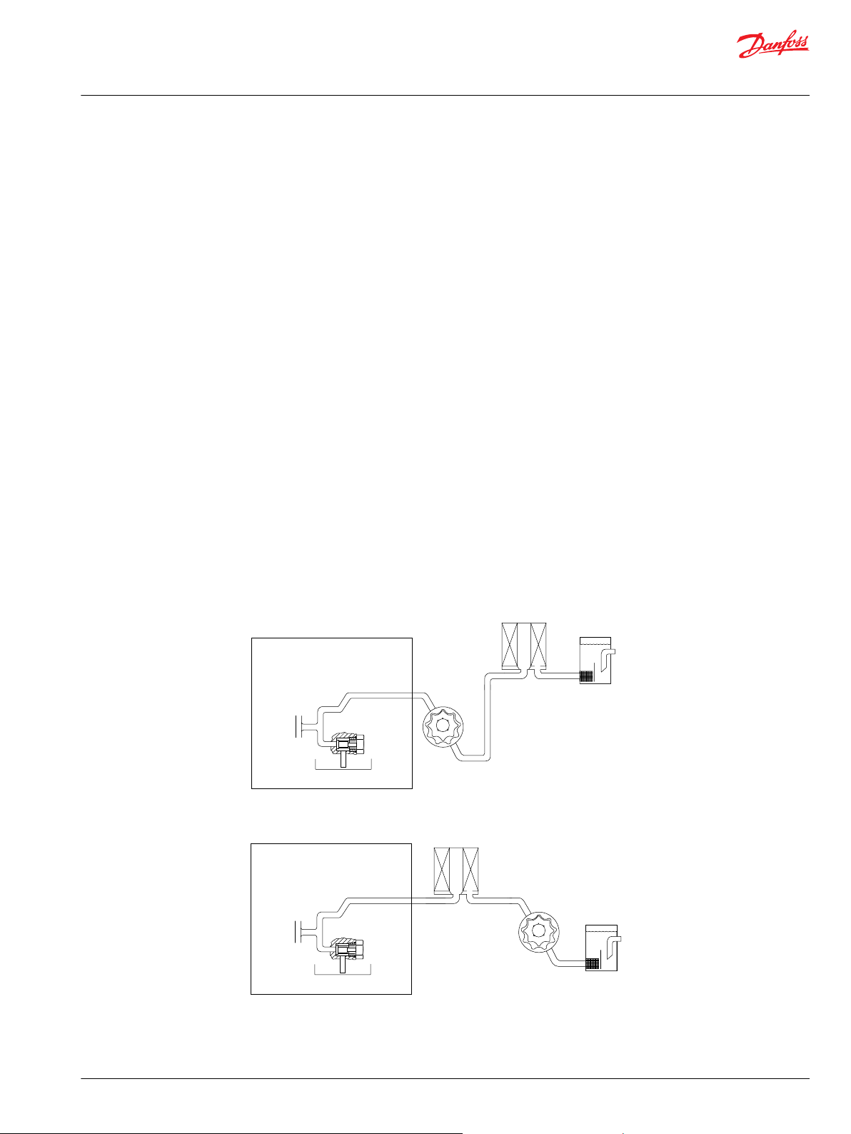
Non-feedback proportional hydraulic control
schematic
©
Danfoss | November 2020 BC152886482857en-000302 | 5
Page 6
Piston Swashplate
Roller bearing
Valve plate
Ball bearing
P400160
Technical Information
Series 42 4T Axial Piston Tandem Pumps Size 41/51
General Description
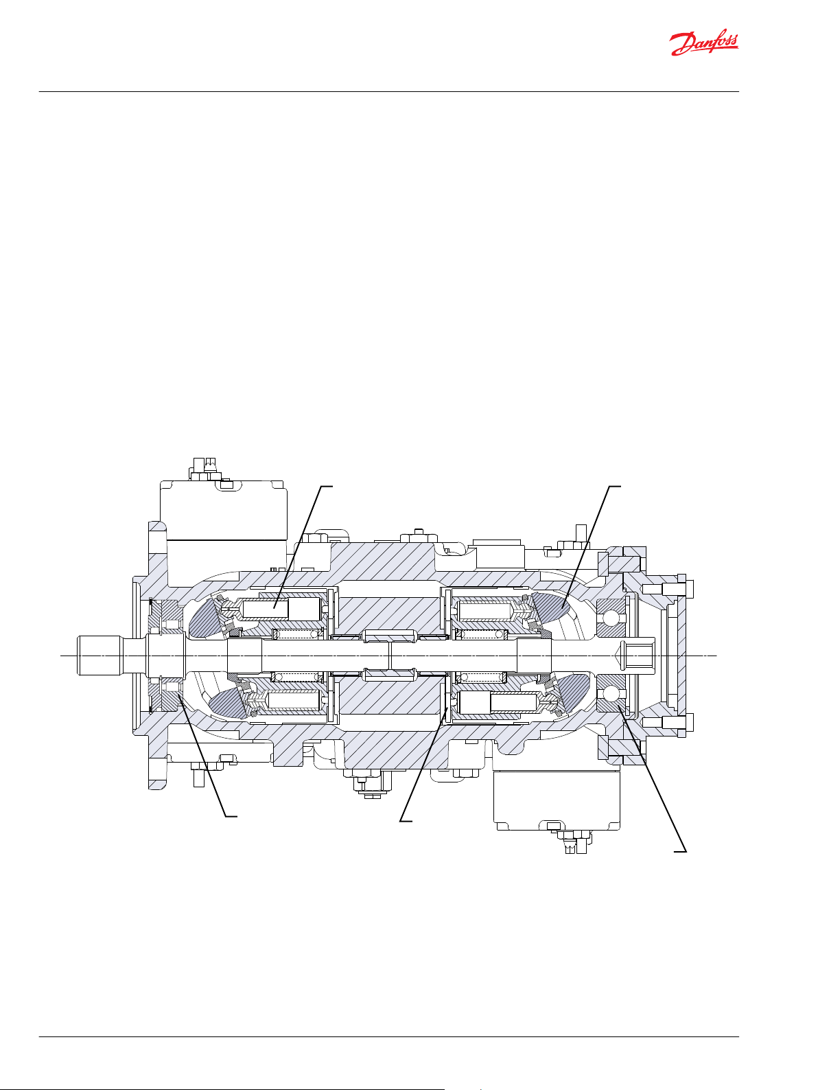
Basic Design
S42 Integrated Tandem Pumps (4T) are advanced hydrostatic units for medium power applications with
maximum loads of 415 Bar [6020 psi] (41 cm3) and 350 Bar [5075 psi] (51 cm3). You can combine these
pumps with a suitable Danfoss motor or other products in a system to transfer and control hydraulic
power.
The 4T axial piston pump is a compact, high power density unit, using the parallel axial piston/slipper
concept in conjunction with tiltable swashplates to vary the pumps’ displacements.
Reversing the angle of the swashplate reverses the flow of fluid from the pump, and reversing the
direction of rotation of the motor output. 4T axial piston pumps provide an infinitely variable speed
range between zero and maximum in both forward and reverse.
4T axial piston pumps use a cradle swashplate design with a hydraulic servo control cylinder. Control is
provided through a compact servo control system. Two types of servo controls are available. These
include mechanical hydraulic actuated feedback controls, and hydraulic proportional control. These
controls feature low hysteresis and responsive performance.
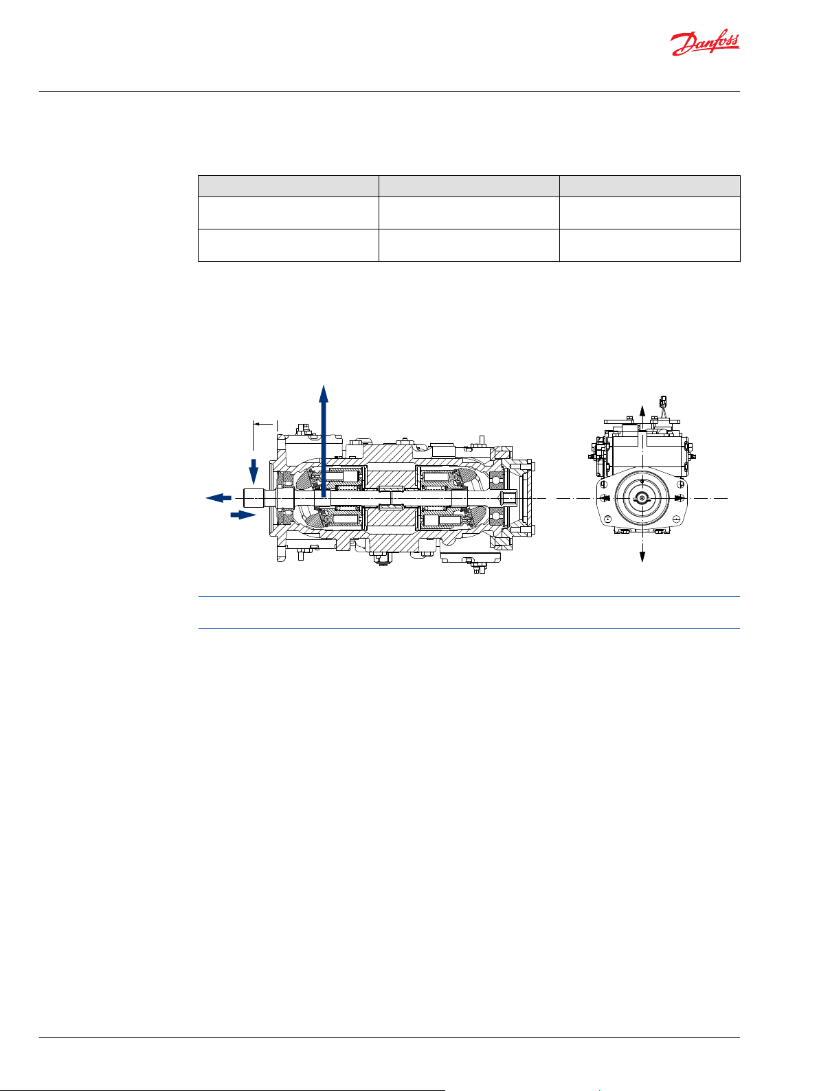
Cross-sectional view
6 | © Danfoss | November 2020 BC152886482857en-000302
Page 7
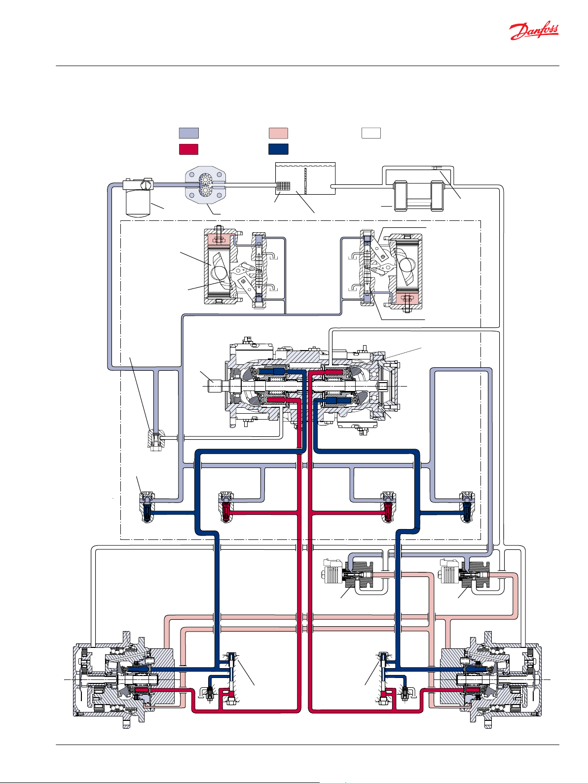
Reservoir
Suction
Screen
Charge Pressure
Relief Valve
Servo Control
Cylinder
Swash Plate
Bypass Check
Heat Exchanger
Control Handle
Displacement
Control Spool
Cylinder Block
Assembly
Valiable
Displacement
Pump
Charge Pump
System Pressure
Control Pressure
Low Loop Pressure
Suction/Case Drain/
System Return
Charge Pressure
P106 147E
Loop
Flushing
Valve
Motor Gear boxMotorGear box
Loop
Flushing
Valve
Input
Shaft
Charge check/
HPRV valve
Brake release
control valve
Motor displacement
control valve
Filter
Technical Information
Series 42 4T Axial Piston Tandem Pumps Size 41/51
General Description
System Diagram
©
Danfoss | November 2020 BC152886482857en-000302 | 7
Page 8
P400161
M4
M2
M1M1 M2
M6
B C DA
M5
L2
M6
Front Rear
M5
GearboxGearbox MotorMotor
M4
L1
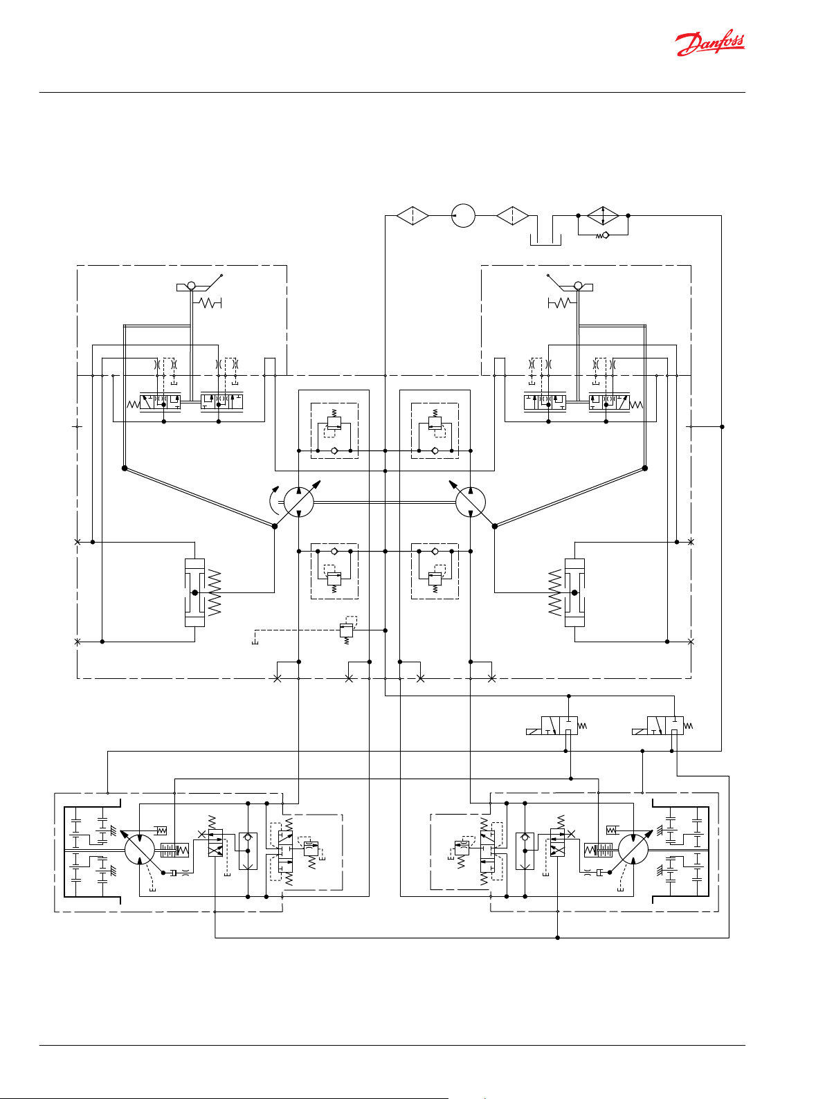
Technical Information
Series 42 4T Axial Piston Tandem Pumps Size 41/51
General Description
System Schematic
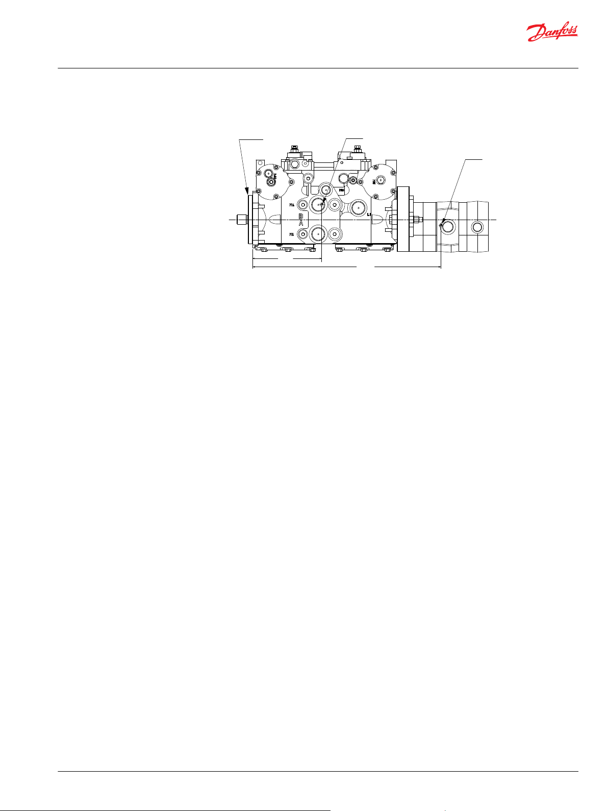
4T Axial Piston Pump
The illustration above shows a schematic of a 4T axial piston pump. System ports A, C and B, D connect to
the high pressure work lines. Return fluid is received from its inlet port and discharged through the outlet
port. Flow direction is determined by swashplate position. You can read system port pressure through
ports M1 and M2. The pump has two case drains (L1 and L2) to ensure there is lubricating fluid in the
8 | © Danfoss | November 2020 BC152886482857en-000302
Page 9

Technical Information
Series 42 4T Axial Piston Tandem Pumps Size 41/51
General Description
system. This schematic includes a manual displacement control. For other control schematics see the
related control section: Manual Displacement Control (MDC) on page 26, Non-Feedback, Proportional
Hydraulic (NFPH) Control on page 32
©
Danfoss | November 2020 BC152886482857en-000302 | 9
Page 10
Technical Information
Series 42 4T Axial Piston Tandem Pumps Size 41/51
Technical Specifications
System Specifications
General Specifications
Feature Series 42 4T
Pump type
Direction of input rotation Clockwise or counterclockwise
Recommended installation position
Other system requirements Independent braking system, suitable reservoir and heat exchanger.
Hardware Features
Pump configuration Single variable pump
Displacement
Weight
Mass moment of inertia
Type of front mounting flange
(SAE flange size per SAE J744)
Port connections SAE-twin ports, radial, opposite side ports
System pressure regulation
Displacement limiters Option
Input shaft options Splined
Auxiliary mounting pad
(SAE pad per SAE J744)
Control options MDC, NFPH
Loop flushing None
3
cm
[in3]
kgf
[lbf]
kg•m
[lbf•ft2]
bar
[psi]
In-line, axial piston, positive displacement pumps including cradle
swashplate and servo control
Pump installation recommended with control position on the top or
side. Consult Danfoss for non conformance guidelines. The housing
must always be filled with hydraulic fluid.
40.9 [2.50] x 2 51 [3.11] x 2
MDC: 76 [168]
NFPH: 72 [158]
2
0.0072 [0.0054] 0.0076 [0.0056]
2 Bolt SAE C (4 additional bolt holes available)
210-415 [3045-6020] 210-325 [3045-4715]
SAE A (9 tooth, 11 tooth and 13 tooth)
SAE B (13 tooth)
System Parameters
Case pressure
Continuous pressure
Maximum pressure (cold start)
bar
[psi]
bar
[psi]
3 [44]
10.3 [150]
Pressure Limits
bar
[psi]
bar
[psi]
3
41 51
350 [5075] 325 [4713]
450 [6265] 400 [5800]
Displacement cm
Rated pressure
Maximum pressure
10 | © Danfoss | November 2020 BC152886482857en-000302
Page 11
Technical Information
Series 42 4T Axial Piston Tandem Pumps Size 41/51
Technical Specifications
Speed Limits
Frame size cm
Minimum speed
Rated speed at maximum
displacement
Maximum speed at maximum
displacement
Charge Pump Displacement and Setting Pressure
Frame size cm
Internal -
Charge relief
valve settings
Theoretical Flow
Frame size cm
Theoretical flow at rated speed
Standard
Optional 14-24 [203-340]
3
-1
min
(rpm)
-1
min
(rpm)
-1
min
(rpm)
3
cm3/rev
[in3/rev]
bar
[psi]
3
l/min
[US gal/
min]
41 51
500
3200 2900
3450 3400
41 51
none none
20 [290]
41 51
131 [34.6] 148 [39.1]
Hydraulic Fluid Parameters
Check/high Pressure Relief Valve
Options
Setting —
bar
[psi]
No relief valve /check only Relief valve / check
210-415 [3045-6020] or by setting available
210, 250, 280, 300, 325, 345, 360, 385, 415
Fluid temperature range
Minimum -40 °C [-40 °F] Intermittent, cold start
Maximum continuous 104 °C [220 °F] -
Maximum 115 °C [240 °F] Intermittent
Fluid cleanliness level
Required fluid cleanliness level ISO 4406 Class 22/18/13
Fluid viscosity
Minimum 7.0 mm2/s (cSt) Intermittent
Recommended operating range 12-60 mm2/s (cSt) Maximum 1600 mm2/s (cSt) Intermittent, cold start
©
Danfoss | November 2020 BC152886482857en-000302 | 11
Page 12

W
Technical Information
Series 42 4T Axial Piston Tandem Pumps Size 41/51
Operating Parameters
System Requirements
Independent braking system
Warning
Unintended vehicle or machine movement hazard. The loss of hydrostatic drive line power, in any
mode of operation (forward, neutral, or reverse) may cause the system to lose hydrostatic braking
capacity. You must provide a braking system, redundant to the hydrostatic transmission, sufficient to
stop and hold the vehicle or machine in the event of hydrostatic drive power loss.
Reservoir
Design the system to accommodate maximum volume changes during all system operating modes and
to promote de-aeration of the fluid as it passes through the tank. Minimum reservoir volume is 5/8 of the
maximum charge pump flow per minute with a minimum fluid volume equal to 1/2 of the maximum
charge pump flow per minute. At the maximum return flow, this allows 30 seconds fluid dwell for
removing entrained air. This is adequate for a closed reservoir (no breather) in most applications. Position
the reservoir outlet (pump inlet) above the bottom of the reservoir to take advantage of gravity
separation and prevent large foreign particles from entering the charge inlet line. Use a 100 - 125 μm
screen over the outlet port. Position the reservoir inlet (fluid return) so that flow to the reservoir is
discharged below the normal fluid level, and directed into the interior of the reservoir for maximum dwell
and efficient de-aeration. Use a baffle (or baffles) between the inlet and outlet ports to promote deaeration and reduce surging of the fluid.
System Parameters
Speed limits
Rated speed is the speed limit we recommend at full power condition and is the highest value at which
you can expect normal life. Maximum speed is the highest operating speed we permit. You cannot
operate above this speed without risk of immediate failure and loss of drive line power and hydrostatic
braking capacity (which may create a hazard). In mobile applications, you must apply this pump with a
speed speed below the stated maximum. Consult Pressure and Speed Limits, BC152886484313, when
determining speed limits for a particular application.
Inlet pressure
Control charge pump inlet conditions to achieve expected life and performance. Ensure a continuous
inlet pressure of not less than 0.8 bar absolute (not more than 6 in Hg vacuum). Normal pressures less
than 0.7 bar absolute (greater than 9 in Hg vacuum) indicate inadequate inlet design or a restricted filter.
Pressures less than 0.7 bar absolute (greater than 9 in Hg vac) during cold start are possible, but should
improve quickly as the fluid warms. Never exceed the maximum inlet vacuum.
Theoretical output
The theoretical maximum flow at rated speed is a simple function of pump displacement and speed. This
is a good gauge for sizing a companion motor. This does not take into account losses due to leakage or
variations in displacement.
Case pressure
Under normal operating conditions, the rated case pressure must not be exceeded. During cold start
case pressure must be kept below maximum intermittent case pressure. Size drain plumbing accordingly.
12 | © Danfoss | November 2020 BC152886482857en-000302
Page 13

W
C
Technical Information
Series 42 4T Axial Piston Tandem Pumps Size 41/51
Operating Parameters
System pressure
System pressure is the differential pressure between high pressure system ports. It is the dominant
operating variable affecting hydraulic unit life. High system pressure, which results from high load,
reduces expected life. Hydraulic unit life depends on the speed and normal operating, or weighted
average, pressure that can only be determined from a duty cycle analysis.
Application pressure - is the high pressure relief or pressure limiter setting normally defined within the
order code of the pump. This is the applied system pressure at which the driveline generates the
maximum calculated pull or torque in the application. Maximum Working Pressure - is the highest
recommended Application pressure.
Maximum working pressure is not intended to be a continuous pressure. Propel systems with
Application pressures at, or below, this pressure should yield satisfactory unit life given proper
component sizing.
Maximum pressure is the highest allowable Application pressure under any circumstance. Application
pressures above Maximum Working Pressure will only be considered with duty cycle analysis and factory
approval.
Minimum pressure must be maintained under all operating conditions to avoid cavitation.
Warning
Hydraulic Fluid Parameters
All pressure limits are differential pressures referenced to low loop (charge) pressure. Subtract low loop
pressure from gauge readings to compute the differential.
Hydraulic fluid
Ratings and data are based on operating with hydraulic fluids containing inhibitors to prevent oxidation,
rust, and foam. These fluids must possess good thermal and hydrolytic stability to prevent wear, erosion,
and corrosion of the internal components.
Caution
Never mix hydraulic fluids of different types.
Temperature and viscosity
Ensure the application satisfies temperature and viscosity requirements concurrently. The data shown in
the tables on Hydraulic Fluid Parameters on page 11, assume petroleum-based fluids.
High temperature limits apply at the hottest point in the transmission, which is normally the case drain.
Always run the pump at or below the continuous temperature. Never exceed maximum temperature.
Durability of transmission components is not affected by cold oil, but it may affect the ability of oil to flow
and transmit power. Keep temperatures 16 °C [30 °F] above the pour point of the hydraulic fluid. The
minimum temperature relates to physical properties of component materials.
For maximum unit efficiency and bearing life, keep fluid viscosity in the continuous viscosity range.
During brief occasions of maximum ambient temperature and severe duty cycle operation, minimum
viscosity may occur. The system should encounter maximum viscosity only at cold start.
Size heat exchangers to keep the fluid temperature and viscosity within these limits. Test the system to
verify that these temperature limits are not exceeded.
©
Danfoss | November 2020 BC152886482857en-000302 | 13
Page 14

Based on SI units
= (l/min)
Input torque M = (N•m)
Input power P = = (kW)
Based on US units
= (US gal/min)
Input torque M = (lbf•in)
Input power P = = (hp)
Vg • n • η
v
1000
Vg • ∆p
20 • π • η
m
Q • ∆p
600 • η
t
M • n • π
30 000
Vg • n • η
v
231
Vg • ∆p
2 • π • η
m
Q • ∆p
1714 • η
t
M • n • π
198 000
Flow
Torque
Power
Technical Information
Series 42 4T Axial Piston Tandem Pumps Size 41/51
Operating Parameters
Sizing Equations
Use these equations to help choose the right pump size and displacement for your application.
Variables
SI units [US units]
Vg= Displacement per revolution cm3/rev [in3/rev]
PO= Outlet pressure bar [psi]
Pi= Inlet pressure bar [psi]
∆p = pO - pi (system pressure) bar [psi]
n = Speed min-1 (rpm)
ηv= Volumetric efficiency
ηm= Mechanical efficiency
ηt= Overall efficiency (ηv • ηm)
14 | © Danfoss | November 2020 BC152886482857en-000302
Page 15
Reservoir
Filter
Charge
pum p
Charge
relief
valve
To pump case
Internal
To low pressur e
side of loop and
servo contro l
Strainer
P400162
P400163
Charge
Filter
pump
Charge
relief
valve
To pump case
Internal
To low pressure
side of loop and
servo control
Reservoir
Strainer
Technical Information
Series 42 4T Axial Piston Tandem Pumps Size 41/51
System Design Parameters
Fluid and Filtration
To prevent premature wear, use only new clean fluid. Use a filter capable of controlling fluid cleanliness
to ISO 4406 Class 22/18/13 (SAE J1165).
Locate the filter on the inlet (suction filtration) or discharge (charge pressure filtration) side of the charge
pump: 4T axial piston pumps are available with provisions for either configuration.
The selection of a filter depends on a number of factors including the contaminant ingression rate, the
generation of contaminants in the system, the required fluid cleanliness, and the desired maintenance
interval. Use filters that meet the above requirements of efficiency and capacity.
Filter efficiency can be measured with a Beta ratio (βX). For simple suction-filtered closed circuit
transmissions and open circuit transmissions with return line filtration, a filter with a β-ratio within the
range of β
and closed circuits with cylinders being supplied from the same reservoir, a higher filter efficiency is
recommended. This also applies to systems with gears or clutches using a common reservoir. For these
systems, a charge pressure or return filtration system with a filter β-ratio in the range of β
10) or better is typically required.
Because each system is unique, only a thorough testing and evaluation program can fully validate the
filtration system. Please see Design Guidelines for Hydraulic Fluid Cleanliness, BC152886482150, Technical
Information for more information.
= 75 (β10 ≥ 2) or better has been found to be satisfactory. For some open circuit systems,
35-45
= 75 (β10 ≥
15-20
Filtration Configuration
Locate the filter on the inlet (Suction filtration) or discharge (Charge pressure filtration) side of the
external charge pump.
Suction filtration
Charge pressure filtration, full flow
©
Danfoss | November 2020 BC152886482857en-000302 | 15
Page 16
Technical Information
Series 42 4T Axial Piston Tandem Pumps Size 41/51
System Design Parameters
Mounting Flange Loads
Adding tandem mounted auxiliary pumps and/or subjecting pumps to high shock loads may result in
excessive loading of the mounting flange. Design pump applications to stay within the allowable shock
load and continuous load moments.
Shock load moment MS is the result of an instantaneous jolt to the system. Rated (continuous) load
moments MR are generated by the typical vibratory movement of the application.
Estimated maximum and continuous acceleration factors for some typical applications are shown in the
table.
Applications which experience extreme resonant vibrations may require additional pump support.
Exceeding the allowable overhung values listed below will require additional pump support.
G-factors for sample applications
Application Continuous (vibratory)
Skid steer loader 4 10
Trencher (rubber tires) 3 8
Asphalt paver 2 6
Windrower 2 5
Turf care vehicle 1.5 4
Vibratory roller 6 10
acceleration
(GR)
Maximum (shock) acceleration
(GS)
Allowable overhung load moments
Rated load moment (MR) Shock load moment (MS)
1441 N•m [12750 in•lbf] 3413 N•m [30200 in•lbf]
Estimating Overhung Load Moment
MR = GR (W1L1 + W2L2 + ... +WnLn)
MS = GS (W1L1 + W2L2 + ... +WnLn)
Where:
MRRated load moment N•m [lbf•in]
MSShock load moment N•m [lbf•in]
GRRated (vibratory) acceleration (G-factors: unitless)
GSMaximum shock acceleration (G-factors: unitless)
W Weight of the pump N [lbf]
L Distance from mounting flange to the center of gravity mm [in]
16 | © Danfoss | November 2020 BC152886482857en-000302
Page 17
Mounting flange
L2
Pump 1
Center of gravity
Pump 2
Center of gravity
P400164
L1
Technical Information
Series 42 4T Axial Piston Tandem Pumps Size 41/51
System Design Parameters
Overhung load moments
Case Drain
The front and rear pumps are connected by cast passages in the housing. The charge relief valve
discharges oil into the front housing. In order to provide positive housing flow thru both pumps, use of
rear case drain is required. The front case drain should only be used if the pumps are used as a common
drain manifold for the vehicle whereas external drain flow is brought into the rear case port and
discharged out the front.
External Shaft Load and Bearing Life
Bearing life is a function of speed, pressure, and swashplate angle, plus any external loads. Other factors
that affect life include fluid type, viscosity, and cleanliness.
In vehicle propulsion drives with no external loads—where the speed, pressure, and swashplate angle are
often changing—normal bearing B10 (90% survival) life exceeds the hydraulic unit life.
In non-propel drives, such as conveyors or fan drives, the operating speed and pressure may be nearly
constant leading to a distinctive duty cycle compared to that of a propulsion drive. In these types of
applications, we recommend a bearing life review. 4T axial piston pumps use bearings that can accept
some incidental external radial and thrust loads. However, any amount of external load reduces the
expected bearing life.
The allowable radial shaft loads are a function of the load position, orientation, and operating pressures
of the hydraulic unit. In applications where you cannot avoid external shaft loads, minimize the impact on
bearing life by orienting the load to the 0° or 180° position.
The maximum allowable radial load is calculated as: Re = Me / L
Where:
L Distance from mounting flange to point of load
M
e
R
e
T
out
F
B
Maximum external moment
Maximum radial side load
Thrust load
Load to cylinder block kit
©
Danfoss | November 2020 BC152886482857en-000302 | 17
Page 18
P400165
0 Re
180 Re
90 Re
270 Re
F
B
L
T
out
R
e
T
in
Technical Information
Series 42 4T Axial Piston Tandem Pumps Size 41/51
System Design Parameters
Allowable shaft loads
Displacement (cm3) 41 51
M
e
N•m [in•lbf]
T
OUT
N [lbf]
Avoid thrust loads in Tin direction.
If continuously applied external radial loads are 25% of the maximum allowable or more, or thrust loads
are known to occur, contact your Danfoss representative for an evaluation of unit bearing life.
Use clamp-type couplings where radial shaft side loads are present.
External shaft load orientation
111
[982]
1110
[250]
90
[800]
1110
[250]
Hydraulic Unit Life
Use the table and drawing to determine maximum allowable radial loads (Re), based on the maximum
external moment (Me) and the distance (L) from the mounting flange to the load.
Hydraulic unit life is the life expectancy of the hydraulic components. Hydraulic unit life is a function of
speed and system pressure. However, system pressure is the dominant operating variable. High pressure,
which results from high load, reduces expected life.
Design the hydraulic system to a projected machine duty cycle. Know the expected percentages of time
at various loads and speeds. Ask your Danfoss representative to calculate an appropriate pressure based
your hydraulic system design. If duty cycle data is not available, input power and pump displacement are
used to calculate system pressure.
All pressure limits are differential pressures (referenced to charge pressure) and assume normal charge
pressure.
4T axial piston pumps will meet satisfactory life expectancy if applied within the parameters specified in
this bulletin. For more detailed information on hydraulic unit life see BC152886484313, Pressure and
Speed Limits.
18 | © Danfoss | November 2020 BC152886482857en-000302
Page 19

100
80
95
90
85
Efficienc
y —
%
0
25 50
75
100
Speed,% of Rated Speed
V
o
l
u
m
e
t
r
i
c
E
f
f
i
c
i
e
n
c
y
1
b
2
5
0
0
ps
i
]
-
7
0
a
r [
V
o
l
u
m
e
t
r
i
c
E
f
f
i
c
i
e
n
c
y
b
5
0
0
0
ps
i
]
-
3
4
5
ar
[
O
v
e
r
a
l
l
E
f
f
i
c
5
0
0
p
s
i
]
i
e
n
c
y
-
1
7
0
b
a
r
[
2
O
v
e
r
a
l
l
E
f
f
i
c
i
e
n
c
y
-
3
4
5
b
a
r
[
5
0
0
0
p
s
i
]
P100401E
5000
0
4000
3000
2000
1000
System Pressur
e
0
25 50
75 100
Speed,% of Rated Speed
psi
350
bar
300
250
200
150
100
50
0
8
8
%
8
7
%
8
5
%
8
0
%
P100402E
Technical Information
Series 42 4T Axial Piston Tandem Pumps Size 41/51
System Design Parameters
Efficiency Graphs
The following performance map provides typical volumetric and overall efficiencies for 4T axial piston
pumps. These efficiencies apply for all 4T axial piston pumps at maximum displacement.
Pump performance as a function of operating speed at maximum displacement*
The following performance map provides typical pump overall efficiencies at various operating
parameters. These efficiencies also apply for all 4T axial piston pumps at maximum displacement.
Pump performance at select operating parameters at maximum displacement*
* Assumes viscosity in the continuous range
©
Danfoss | November 2020 BC152886482857en-000302 | 19
Page 20

Technical Information
Series 42 4T Axial Piston Tandem Pumps Size 41/51
Features and Options
Charge Pump
An external charge pump is required on all 4T axial piston pumps units applied in closed circuit
installations to make up for internal leakage, to maintain positive pressure in the main circuit, and to
replace any leakage losses from external valving or auxiliary systems.
The total charge flow requirement is the sum of the charge flow requirement of each of the components
in the system. When initially sizing and selecting hydrostatic units for an applications, it is frequently not
possible to have all of the information necessary to accurately evaluate all aspects of charge pump size
selection. The following procedure will assist the designer in arriving at an initial charge pump selection
for a typical application.
In most 4T axial piston pump applications a general guideline is that the charge pump displacement
(CPG) should be equal to or greater than 10% of the total displacement (TD) of all axial piston units in the
system. This rule assumes that all units are of high speed, axial piston or bent axis design.
Particular application conditions may require a more detailed review of charge pump sizing. System
features and conditions that may invalidate the 10% of displacement rule include (but are not limited to):
•
Operation at low input speeds (below 1500 rpm)
•
Shock loadings
•
Excessively long system lines
•
Auxiliary flow requirements
•
Use of low speed, high torque motors
Charge Relief Valve
If a charge pump of sufficient displacement to meet the 10% of displacement rule is not available or if any
of the above conditions exist which could invalidate the 10% rule, contact your Danfoss representative.
A charge pump sizing worksheet can be found in BC157786484430, Selection of Driveline Components.
Charge Pump Sizing Example:
A system consists of 4T 41cc Pump driving two Series 40 -M35 Fixed Motors:
TD = 41 + 41 + 35 +35= 152 cm
•
CPD = 10 % x TD = 15.2 cm
•
This requires a charge pump displacement of 15.2 cm3 .
The charge relief valve maintains charge pressure at a designated level. 4T axial piston pumps come with
direct-acting poppet style charge relief valves. The valve setting is set at the factory. The setting is screw
adjustable.
The charge pressure settings are nominal values and are based on the charge flow across the charge
relief valve with a fluid viscosity of 28 mm2/s (cSt) [130 SUS] and a pump input speed of 1800 min-1(rpm).
Actual charge pressure differs slightly from the nominal setting when different input speeds are used.
The charge setting is a differential pressure (referenced to case pressure) and measured with the piston
pump at zero swashplate angle (neutral). Charge pressure drops slightly when the pump is in stroke due
to flow demands.
The charge pressure setting for pumps without an internal charge pump is set with an assumed charge
flow of 38 l/min (10 US gal/min). These units must have adequate charge flow supplied to the charge
inlet in order to maintain charge pressure at all times.
3
3
20 | © Danfoss | November 2020 BC152886482857en-000302
Page 21

From Charge
Pump
To Low Side
of Working
Loop & Servo
Control
To Case
P100392E
C
High pressure
side of working loop
Charge check and
high pressure
relief valve
Charge pressure
P100393E
C
Technical Information
Series 42 4T Axial Piston Tandem Pumps Size 41/51
Features and Options
Charge Relief Valve
Caution
Incorrect charge pressure settings may result in the inability to build required system pressure, inability
to control pump, and/or inadequate loop flushing flows. Maintain correct charge pressure under all
operating conditions.
Overpressure Protection
4T axial piston pumps are available with a combination charge check and high pressure relief valve
assembly. High pressure relief valves come in a range of settings as shown in the model code. You may
specify individual port pressure settings. The high pressure relief valve settings are a differential pressure
(referenced to charge pressure) and are set at 3.8 l/min (1 US gal/min) of flow.
We can equip pumps with charge check valves only, if high pressure relief valve protection is not
necessary.
Charge Check and High Pressure Relief Valve
Caution
High pressure relief valves are for transient overpressure protection, not for continuous pressure control.
Operation over relief valves for extended periods of time results in severe heat build up. High flows over
relief valves may result in pressure levels exceeding the nominal valve setting and potential damage to
system components.
©
Danfoss | November 2020 BC152886482857en-000302 | 21
Page 22

Charge pressure
High pressure
side of working
loop
Charge check and
high pressure
relief valve
Bypass
plunger
FLOW
P100394E
C
Technical Information
Series 42 4T Axial Piston Tandem Pumps Size 41/51
Features and Options
Bypass Valve
4T axial piston pumps are available with an optional bypass function for use when pump shaft rotation is
not possible. Use the bypass function to bypass fluid around the variable displacement pump. For
example: you may move a disabled vehicle to a service location or winch it onto a trailer without
operating the prime mover.
The bypass valve is integral to the charge check/high pressure relief valve assembly. Depress the
plungers located in the plugs of the valve assemblies to operate the bypass function. The valves remain
open until the prime mover is started. Charge pressure automatically closes them.
Charge Check and High Pressure Relief Valve with Bypass
Displacement Limiters
Caution
Damage to the hydraulic system may result from operating without charge flow. Bypass valves are for
moving a machine or vehicle for very short distances at very slow speeds. They are NOT tow valves.
4T axial piston pumps are available with adjustable mechanical displacement (stroke) limiters located in
the servo covers. The maximum displacement of the pump can be limited to any value from its maximum
displacement to zero in either direction. The limiters are factory set slightly beyond the maximum
displacement of the pump. Displacement limiters may not be suited to all applications.
Series 42 pump displacement limiters
Shaft Options
4T axial piston pumps are available with a variety of splined and tapered shaft ends. The accompanying
table shows available shaft sizes and torque ratings. Maximum torque ratings are based on shaft torsional
strength and assume a maximum of 200 000 load reversals.
22 | © Danfoss | November 2020 BC152886482857en-000302
Page 23

0
¯ -0.05P
(+.000)
(-.002)
Spline Engagement
for Torque
Em ax.
Mounting
Flange
Dm ax.
C
max.
B
max.
R 0.8 (.03)
max.
Coupling
F
min.
2.3 (.09)
Cutter clearance
With
Undercut
Without
Undercut
P001614E
Technical Information
Series 42 4T Axial Piston Tandem Pumps Size 41/51
Features and Options
Use ANSI B92.1 Class 5 mating splines for splined output shafts. Danfoss external splines are modified
Class 5 fillet root side fit. The external spline major diameter and circular tooth thickness dimensions are
reduced in order to insure a clearance fit with the mating spline.
Shaft Availability and Torque Rating*
Shaft Max. torque Max. torque
15 tooth spline, 16/32 pitch 362 N•m [3200 in•lbf ] 192 N•m [1700 in•lbf ]
19 tooth spline, 16/32 pitch 734 N•m [6500 in•lbf ] 340 N•m [3000 in•lbf ]
* The limitations of these input shafts constrain the allowable auxiliary coupling torque.
Auxiliary Mounting Pads
Auxiliary mounting pads are available on all 4T axial piston pumps to mount auxiliary hydraulic pumps.
We include a sealed (oil tight) shipping cover as standard equipment. The shipping cover seals case
pressure and you can use it as a running cover if desired.
Since the auxiliary mounting pad operates under case pressure, you must use an O-ring to seal the
auxiliary pump to the pad. The drive coupling is lubricated with oil from the main pump case.
Spline specifications and torque ratings are shown in the accompanying table.
All mounting pads meet SAE J744 specifications.
•
The sum of main and auxiliary pump torque must not exceed stated maximum.
•
All torque values assume a 58 RC shaft spline hardness on mating pump shaft. Maximum torque is
•
based on maximum torsional strength and 200 000 load reversals.
Applications with severe vibratory or high G-force (shock) loading may require additional structural
•
support to prevent leaks or mounting flange damage. Refer to Mounting flange loads for additional
information.
Auxiliary Pad*
Pad size Spline Minimum spline length
(mm [in])
SAE A 9 tooth 16/32 pitch 13.5 [0.53] 107 [950]
SAE A special 11 tooth 16/32 pitch 13.5 [0.53] 147 [1300]
SAE A special 13 tooth 16/32 pitch 14.2 [0.56] 248 [2200]
SAE B 13 tooth 16/32 pitch 14.2 [0.56] 248 [2200]
Maximum torque (N•m
[lbf•in])
* Allowable Auxiliary coupling torque is subject to limitations of the input shaft.
This drawing provides the dimensions for the auxiliary pump mounting flange and shaft. Auxiliary pump
mounting flanges and shafts with these dimensions are compatible with the auxiliary mounting pads on
4T axial piston pumps. For auxiliary pad dimensions, see Auxiliary Mounting Pads on page 48.
©
Danfoss | November 2020 BC152886482857en-000302 | 23
Page 24

Technical Information
Series 42 4T Axial Piston Tandem Pumps Size 41/51
Features and Options
Auxiliary pump mating dimensions
Pad Size P B C D E F
SAE A mm [in] 82.55 [3.250] 8.1 [0.32] 12.7 [0.500] 44 [1.73] 15 [0.59] 13.5 [0.53]
SAE B mm [in] 101.6 [4.000] 11.4 [0.45] 15.2 [0.60] 46 [1.81] 17.5 [0.69] 14.2 [0.56]
Center Coupling
The two pump shafts are connected with a center-section coupling that is a 22 tooth spline with a 24/48
pitch. The torque transmitted through the center coupling is the sum of the rear kit torque and the
auxiliary pump torque. The maximum torque rating of the auxiliary pad may be reduced from the values
in the above table due to center coupling limitations.
22 tooth Center-Section Coupling Torque Rating
Rating Torque in N•m [lbf•in] 22T
Maximum
Continuous
347 [3071]
243 [2151]
Control Selection
4T axial piston pumps use a servo control system with two types of control options. Manual Displacement
Controls (MDC) are feedback controls that provide and maintain a set displacement for a given input. The
MDC includes options for a Neutral Start Switch (NSS), backup alarm , and a solenoid override to neutral.
Non-Feedback Proportional Hydraulic controls (NFPH) is available to control the pump without
mechanical feedback.
All controls provide smooth, stepless positive control of the transmission in either direction. Optional
servo supply and drain orifices are available for special response needs.
Typical Control Applications
Machine Function MDC NFPH
Roller/compactor
Asphalt paver
Skid steer loader Propel
Articulated loader Propel
Utility tractor Propel
Windrower Propel
Trencher
Ag sprayer Propel
Specialized harvesters
(sod, fruit, nut, etc.)
Commercial mower Propel
Rock drill Propel
Drill rig
Sweeper
Propel
Vibratory drive
Propel
Propel
Chain drive
Propel
Auxiliary drive
Drill drive
Pull downe
Propel
Fan
24 | © Danfoss | November 2020 BC152886482857en-000302
Page 25

Technical Information
Series 42 4T Axial Piston Tandem Pumps Size 41/51
Features and Options
Typical Control Applications (continued)
Machine Function MDC NFPH
Aerial lift Propel
Fork lift Propel
Brush / stump cutter
Airport vehicle Propel
Dumper Propel
Propel
Cutter drive
©
Danfoss | November 2020 BC152886482857en-000302 | 25
Page 26

Technical Information
Series 42 4T Axial Piston Tandem Pumps Size 41/51
Features and Options
Manual Displacement Control (MDC)
The Manual Displacement Control (MDC) converts a mechanical input signal to a hydraulic signal. The
hydraulic signal positions the servo piston, tilting the swashplate to vary the pump’s displacement and
flow direction.
The position of the swashplate is proportional to the mechanical input signal. The control has mechanical
feedback that regulates the servo valve in relation to swashplate position to maintain displacement at
the commanded level regardless of changes in system pressure.
The full featured 4T axial piston pumps manual control consists of two manual displacement controls
with backup alarm swiches. One of the controls incorporate a neutral override (NOR) solenoid and brake
release port. The other control housing drains through the first control housing to provide neutral
override function.
Manual controls for use on one pump are also available and can be used in combination with another
type of control on the other pump. The servo control valve has variable geometry porting to regulate
swashplate response relative to input command. The control performs small displacement change
commands with maximum controllability throughout the entire stroking range of the pump. It completes
large displacement change commands with rapid swashplate response. Optional servo supply and drain
orifices are available for special response needs.
The control also has a full over-travel spool that allows input at a faster rate than swashplate movement
without damage to the control. Any swashplate position error is feed back to the servo valve for instant
correction.
Features and Benefit of MDC
The MDC is a high gain control: Small movements of the control handle move the servo valve to full
•
open position porting maximum flow to the servo cylinder.
The full over-travel spool design allows rapid changes in input signal without damaging the control
•
mechanism.
The MDC provides a fast response with low input force.
•
Precision parts provide repeatable and accurate displacement settings.
•
Mechanical feedback maintains pump displacement regardless of changes in system pressure.
•
The operator is isolated from swashplate vibration.
•
The swashplate and servo cylinder, as well as the control valve, are spring centered so the pump
•
returns quickly to neutral in the absence of control input.
The pump returns to neutral:
if the prime mover is shut down;
•
if the external control linkage fails at the control handle;
•
if there is a loss of charge pressure.
•
26 | © Danfoss | November 2020 BC152886482857en-000302
Page 27

-b -a
a b
100%
100%
P001015E
Displacement
M5
M4
P100404E
Technical Information
Series 42 4T Axial Piston Tandem Pumps Size 41/51
Features and Options
Control Input Signal
The figure and table below relate the input electrical signal to pump displacement, (swashplate position),
for each coil configuration.
Pump displacement versus Electrical signal
Response Time
You can tailor the time to change from zero to maximum displacement using orifices incorporated in the
gasket between the control and pump housing. Using orifices you can match swashplate response to the
acceleration and deceleration requirements of your application. Verify proper orifice selection by testing.
MDC Response Time (Maximum to Maximum)
Frame size (cm3) Fast (no orifice) Medium Slow (standard)
41/51 0.6 sec 1.6 sec 2.5 sec
Neutral to maximum swashplate response is approximately 60% of the time for maximum to maximum
sawashplate travel. For other response times please contact your Danfoss representative.
MDC Schematic
©
Danfoss | November 2020 BC152886482857en-000302 | 27
Page 28

Charge Pressure
Servo Control
Valve
MDC Handle
Servo Piston
Feedback
Linkage
P100403E
P100407E
Technical Information
Series 42 4T Axial Piston Tandem Pumps Size 41/51
Features and Options
Cross-section of MDC
Control Handles
Either straight or clevis (offset) style control handles are available for the MDC. The straight style handle
minimizes the overall height of the pump and control. The clevis style handle provides additional
clearance between the handle and control housing and works well for clevis style linkage installations.
Maximum allowable input torque at the control handle is 17 N•m (150 lbf•in). The maximum allowable
bending moment is 4 N•m (35 in•lbf ).
Pump Flow Direction with MDC
Input Shaft Rotation CW CCW
Handle of rotation CW CCW CW CCW
Port A flow Out In In Out
Port B flow In Out Out In
High pressure servo guage port M4 M5 M4 M5
MDC Handle Options
Electric Solenoid Override to Neutral
This normally open solenoid valve (C) shunts both ends of the servo piston. This prevents the pump from
stroking. When energized, the valve closes, allowing the pump to operate normally. This option is ideally
suited for operator presence or auto-resume functions without prime mover shut down. This solenoid is
available in 12 or 24 Vdc with 2 Amp. maximum current draw. It is available with DEUTSCH 2-way or with
a Packard Weather-Pack 2-way shroud connector.
28 | © Danfoss | November 2020 BC152886482857en-000302
Page 29

P400167
M4
M5
X7
C
L2
(from
charge pump)
Technical Information
Series 42 4T Axial Piston Tandem Pumps Size 41/51
Features and Options
Emergency Override to Neutral with Port for Brake Pressure Release
This solenoid valve (C) operates as the override to neutral above, and drains a spring-applied,
hydraulically-released brake (port X7). Energizing the valve allows the pump to operate as normal, while
also charging port X7 to release the brake. This option is ideally suited for emergency stop functions
without prime mover shut down. The solenoid is available in 12 or 24 Vdc with 2 Amp. maximum current
draw. It is available with DEUTSCH 2-way or with a Packard Weather-Pack 2-way shroud connector.
Electric Override to Neutral Specifications
Solenoid State at Override Activation De-energized
Voltage 12 or 24 Vdc
Maximum Current 2 A
Hydraulic Schematic for MDC with Override Options
©
Danfoss | November 2020 BC152886482857en-000302 | 29
Page 30
Technical Information
Series 42 4T Axial Piston Tandem Pumps Size 41/51
Features and Options
Neutral Start Switch (NSS)
This option provides an electrical switch contact that is closed when the control handle is in its neutral
(0°) position. The switch contact opens when the control handle rotates approximately 1.5° to 2°
clockwise (CW) or counterclockwise (CCW) from neutral.
The switch is rated for 5 Amp. inductive load at 12 or 24 Vdc. It is available with screw terminals (no
connector) or with a Packard Weather-Pack 2-way tower connector or DEUTSCH 2-way connector..
Wire the NSS in series with the engine starting circuit to ensure the pump is in neutral position before
allowing the engine to start.
Neutral Start Switch Specifications
Switch Neutral Position
Voltage
Current Rating
Neutral Play
NSS with Back-up Alarm (BUA) Switch
The BUA switch contact is open until the control handle rotates 2.6° to 3.75° from neutral. The BUA switch
closes when the control handle rotates either clockwise (CW) or counterclockwise (CCW) from neutral
(choose one direction only). The NSS function operates as described above.
The BUA contacts are rated for 2.5 Amp. resistive load at 12 or 24 Vdc. The NSS contacts are rated for 5
Amp. inductive load at 12 or 24 Vdc. This switch is available with screw terminals (no connector) or with a
Packard Weather-Pack 4-way tower connectoror Deutsch 2-way, 4-way connector..
Wire the NSS as described above. Wire the BUA switch in series with a back-up alarm to have the alarm
sound when the operator moves the pump control handle into reverse.
Closed
12 or 24 Vdc
5 A
± 2°
Backup alarm switch option
Switch Neutral Position
Voltage
Current Rating
Alarm Direction
Neutral Play
Open
12 or 24 Vdc
2.5 A
CW or CCW
± 2.6° to 3.75°
Connectors
For available connectors and dimensions, see outline drawings: Manual Displacement Control Options.
30 | © Danfoss | November 2020 BC152886482857en-000302
Page 31

M5
M4
X7
P100408E
D
A
B
C
Technical Information
Series 42 4T Axial Piston Tandem Pumps Size 41/51
Features and Options
Hydraulic schematic for MDC with override options
and NSS
(A) = Backup alarm switch contacts (green wire)
(closed in reverse)
(B) = Neutral start switch w/ backup alarm
(C) = Electric solenoid override to neutral w/
brake release
(D) = Neutral start switch contacts (black wire)
(closed in neutral)
©
Danfoss | November 2020 BC152886482857en-000302 | 31
Page 32

Piston centering spring
Servo piston
P100412E
P400169
M4
M5
L2
X2 X1
Technical Information
Series 42 4T Axial Piston Tandem Pumps Size 41/51
Features and Options
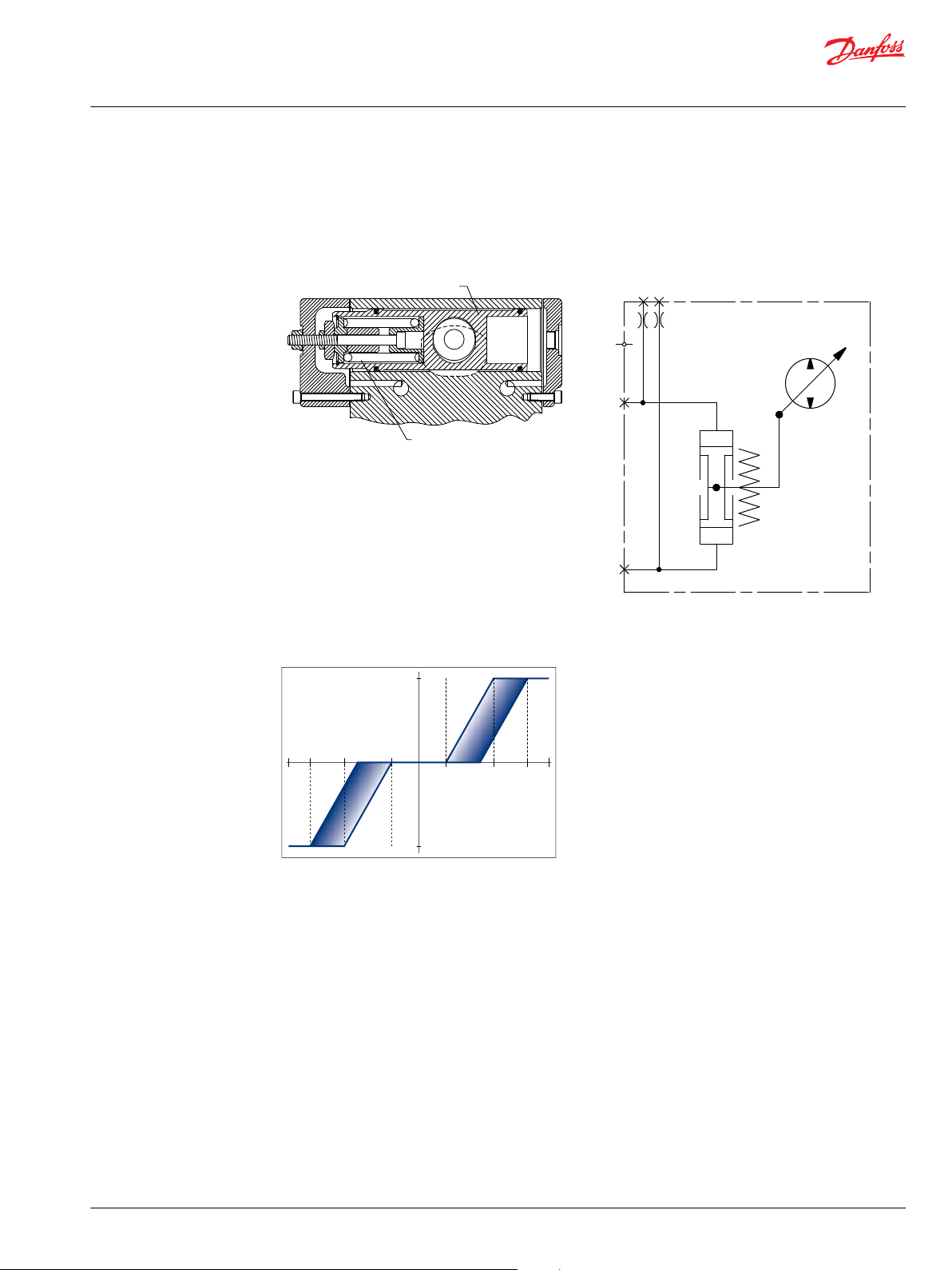
Non-Feedback, Proportional Hydraulic (NFPH) Control
The Non-Feedback Proportional Hydraulic (NFPH) control is a hydraulic proportional control in which an
input pressure signal directly controls the pump servo piston to achieve pump displacement.
4T pumps with NFPH control have a special servo cylinder capable of providing proportional control with
a hydraulic input.
Swashplate position is proportional to the differential signal pressure at ports X1 and X2, but
displacement is also dependent on pump speed and system pressure. This characteristic of non-feedback
controls provides a natural power limiting function by reducing the pump swashplate angle as system
pressure increases. The accompanying graph shows typical operating characteristics.
The system may require tuning through the pump orifice combinations, control pressure supply line
sizing, actuation device output pressure and flow adjustments to achieve proper vehicle performance
characteristics.
Pump displacement versus signal pressure
Non-feedback proportional hydraulic control
schematic
Pump Flow Direction with NFPH control
Input Shaft Rotation
High pressure at port:
Port A flow
Port B flow
High servo gauge port
CW CCW
X1 X2 X1 X2
Out In In Out
In Out Out In
M4 M5 M4 M5
32 | © Danfoss | November 2020 BC152886482857en-000302
Page 33

D
i
s
p
l
a
c
e
m
e
n
t
100%
100%
15 18
6
6
1518
P001628E
Signal Dp (bar)
Dp system=345bar
Dp system=345bar
Dp system=35bar
Dp system=35bar
Technical Information
Series 42 4T Axial Piston Tandem Pumps Size 41/51
Features and Options
NFPH pump displacement to Input signal
NFPH input signal pressure (bar)
Frame size a b c
28/32 5.5 13.7 17
38/45 5 12.75 16
The values provided in the table above are approximations at 1800 RPM and system delta pressures as
indicated in the graph provided. The values are dependent on input speed and delta pressure operating
conditions.
Features and Benefits of the NFPH control
Eliminates mechanical linkage for flexibility of control design
•
Power limiting characteristic reduces machine power requirements
•
Compatible with dual axis joysticks for dual path applications
•
Smooth operation
•
Connectors and Port locations
Refer to outline drawings.
©
Danfoss | November 2020 BC152886482857en-000302 | 33
Page 34

P400170
Z
Servo Pressure Gauge Port “M4”
Port ISO 11926-1 – 9/
16
-18
Servo Pressure Gauge Port “M5”
Port ISO 11926-1 – 9/
16
-18
Charge Inlet Port “M6”
Port ISO 11926-1 – 7/
8
-14
System Port “B”
Port ISO 11926-1 – 1 5/
16
-12
Case Drain Port “L1”
Port ISO 11926-1 – 1 5/
16
-12
System Port “A”
Port ISO 11926-1 – 1 5/
16
-12
System A Pressure Gauge Port “M1”
Port ISO 11926-1 – 9/
16
-18
System B Pressure Gauge Port “M2”
Port ISO 11926-1 – 9/
16
-18
Z
CCW
CW
P400171
Technical Information
Series 42 4T Axial Piston Tandem Pumps Size 41/51
Installation Drawings
Manual Displacement Control (MDC)
Port Description
Port Description Sizes Port Description Sizes
A System port "A" 1 5/16 - 12 M2 System "A" pressure gauge port "M1"9/16 - 18
B System Port "B" 1 5/16 - 12 M1 System "C" pressure gauge port "M1"9/16 - 18
C System Port "C" 1 5/16 - 12 M2 System "D" pressure gauge port "M2"9/16 - 18
D System Port "D" 1 5/16 - 12 M4 x2 Servo pressure gauge port "M4"
L1 Case Drain Port "L1" 1 5/16 - 12 M5 x2 Servo pressure gauge port "M5"
34 | © Danfoss | November 2020 BC152886482857en-000302
9
/16 - 18
9
/16 - 18
Page 35

P400172
Servo Pressure Gauge Port “ M4”
Port ISO 11926-1 – 9/
16
-18
Charge Inlet Port “M6”
Port ISO 11926-1 – 7/
8
-14
Servo Pressure Gauge Port “ M5”
Port ISO 11926-1 – 9/
16
-18
System Port “D”
Port ISO 11926-1 – 1 5/
16
-12
Case Drain Port “L2”
Port ISO 11926-1 – 1 5/
16
-12
System Port “C”
Port ISO 11926-1 – 1 5/
16
-12
System C Pressure Gauge Port “M1”
Port ISO 11926-1 – 9/
16
-18
System D Pressure Gauge Port “M2”
Port ISO 11926-1 – 9/
16
-18
Technical Information
Series 42 4T Axial Piston Tandem Pumps Size 41/51
Installation Drawings
Port Description Sizes Port Description Sizes
L2 Case Drain Port "L2" 1 5/16 - 12 M6 x2 Charge inlet port "M6"
M1 System "A" pressure gauge port "M1"9/16 - 18
7
/8 - 14
©
Danfoss | November 2020 BC152886482857en-000302 | 35
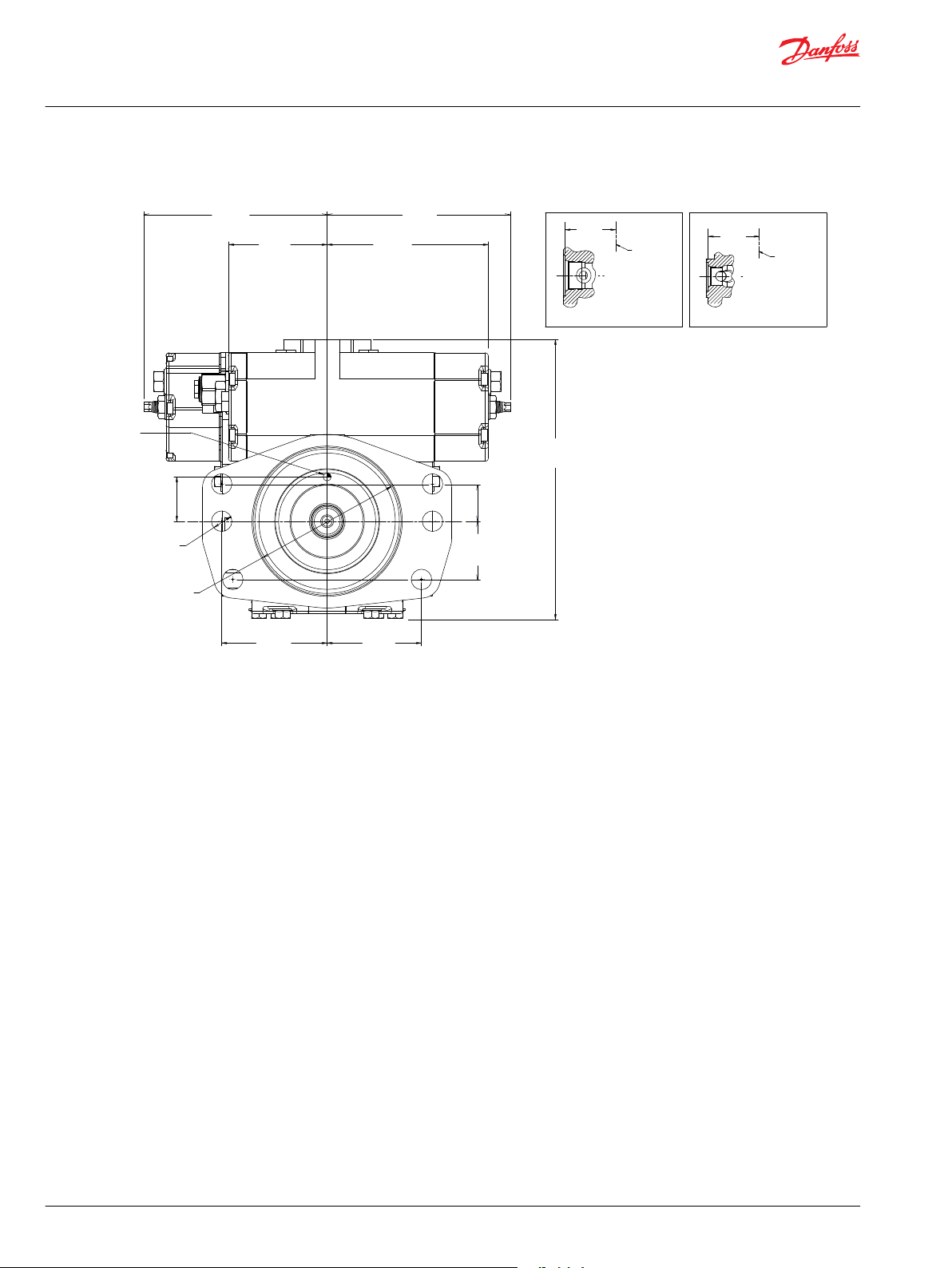
Page 36

[4.72]
120
APPROXIMATE CENTER
AUXILIARY MOUNTING PAD
OPTION J, K, S
DISPLACEMENT LIMITER
OPTION 0, N
OF GRAVITY
G
G
F
F
[4.06]
103
[1.18]
30
[1.52]
38.5
[1.52]
38.5
[3.03]
77
[3.28]
83.2
41.6 [1.64]
131.7 [5.19]
171.7 [6.76]
180.34 [7.10]
192 [7.56]
277 [10.91]
335.4 [13.20]
421.3 [16.59]
433.4 [17.06]
Charge Inlet Port “M6”
Port ISO 11926-1 – 7/
8
-14
System Port “B”
Port ISO 11926-1 – 1 5/
16
-12
P400173
Case Drain Port “L1”
Port ISO 11926-1 – 1 5/
16
-12
System Port “A”
Port ISO 11926-1 – 1 5/
16
-12
Servo Pressure Gauge Port “M4”
Port ISO 11926-1 – 9/
16
-18
Thru
System A Pressure Gauge Port “M1”
Port ISO 11926-1 – 9/
16
-18
System B Pressure Gauge Port “M2”
Port ISO 11926-1 – 9/
16
-18
Z
Ø10.8
±0.5
Servo Pressure Gauge Port “M5”
Port ISO 11926-1 – 9/
16
-18
Neutral Adjust
17 mm HEX
Technical Information
Series 42 4T Axial Piston Tandem Pumps Size 41/51
Installation Drawings
Dimensions
36 | © Danfoss | November 2020 BC152886482857en-000302
Page 37

P400174
Shaft
Center Line
Section F-F
Section G-G
[4.98]
126.5
[4.98]
126.5
[1.54]
39
APPROXIMATE
CENTER
OF GRAVITY
[3.56]
90.5
2X
[3.19]
81
2X
[5 ]
+0
-0.002
Ø127
+0
-0.05
[0.69 ±0.01]
Ø17.57
±0.30
THRU
6X
[1.97]
50
[10.87]
276.06
[1.26]
32
[4.31]
109.5
[3.24]
82.3
BOTH SIDES
SPOT FACE
(M5)
BOTH SIDES
SPOT FACE
(M4)
88
[3.46]
89
[3.50]
C
L
C
L
Z
Technical Information
Series 42 4T Axial Piston Tandem Pumps Size 41/51
Installation Drawings
Adjustable displacement limiters
Shaft rotation CW CCW
Displacement limiter side 1 2 1 2
Limited flow through port B, C A, D A, D B, C
©
Danfoss | November 2020 BC152886482857en-000302 | 37
Determine rotation by viewing pump from the input shaft end. Contact your Danfoss representative for
specific installation drawings.
Page 38

P400175
[0.87]
22
2X
[0.55]
14
[0.5 ]
12.7
0
- 0.5
0
- 0.02
[14.23]
361.4
[4.31]
109.45
90°
±8°
BOTH
HANDLES
[4.49]
114
[1.15]
29.23
LIFTING BRACKET
LIFTING BRACKET
2XM 10X1.5-6H Thd
16 MIN Full Thd Depth
BOTH HANDS
[10.81]
274.55
[9.93]
Section E-E
E
E
252.3
[4.72]
120
[7.56]
192
[7.01]
178
[3.03]
77
[1.91]
48.6
[4.46]
113.3
[4.06]
103
[1.52]
38.5
[1.52]
38.5
[0.76]
19.2
[8.36]
212.3
[4.37]
111
[13.48]
342.4
88
[3.46]
C
L
Charge Inlet Port “M6”
Port ISO 11926-1 – 7/
8
-14
System Port “D”
Port ISO 11926-1 – 1 5/
16
-12
Case Drain Port “L2”
Port ISO 11926-1 – 1 5/
16
-12
System Port “C”
Port ISO 11926-1 – 1 5/
16
-12
Servo Pressure Gauge Port “M4”
Port ISO 11926-1 – 9/
16
-18
Servo Pressure Gauge Port “M5”
Port ISO 11926-1 – 9/
16
-18
System C Pressure Gauge Port “M1”
Port ISO 11926-1 – 9/
16
-18
System D Pressure Gauge Port “M2”
Port ISO 11926-1 – 9/
16
-18
Charge Relief Valve
12.5 mm External Hex
Neutral Adjust
17 mm HEX
Technical Information
Series 42 4T Axial Piston Tandem Pumps Size 41/51
Installation Drawings
38 | © Danfoss | November 2020 BC152886482857en-000302
Page 39

Servo Pressure Gauge Port “M4”
Port ISO 11926-1 – 9/
16
-18
Charge Inlet Port “M6”
Port ISO 11926-1 – 7/
8
-14
Servo Pressure Gauge Port “M5”
Port ISO 11926-1 – 9/16-18
System Port “B”
Port ISO 11926-1 – 1 5/
16
-12
Case Drain Port “L1”
Port ISO 11926-1 – 1 5/
16
-12
System Port “A”
Port ISO 11926-1 – 1 5/
16
-12
System A Pressure Gauge Port “M1”
Port ISO 11926-1 – 9/
16
-18
P400176
System B Pressure Gauge Port “M2”
Port ISO 11926-1 – 9/
16
-18
Z
CCW CW
Z
P400177
Technical Information
Series 42 4T Axial Piston Tandem Pumps Size 41/51
Installation Drawings
Non-Feedback, Proportional Hydraulic (NFPH)
Port Description
©
Danfoss | November 2020 BC152886482857en-000302 | 39
Port Description Sizes Port Description Sizes
A System port "A" 1 5/16 - 12 M1 System “C” pressure gauge port “M1”9/16 - 18
B System Port "B" 1 5/16 - 12 M2 System “D” pressure gauge port “M2”9/16 - 18
C System Port "C" 1 5/16 - 12 M4 x2 Servo pressure gauge port “M4”
D System Port "D" 1 5/16 - 12 M5 x2 Servo pressure gauge port “M5”
L1 Case Drain Port "L1" 1 5/16 - 12 M6 x2 Charge Inlet port “M6”
L2 Case Drain Port "L2" 1 5/16 - 12 X1 Control Port “X1”
9
/16 - 18
9
/16 - 18
7
/8 - 14
9
/
16
Page 40

P400178
Servo Pressure Gauge Port “M4”
Port ISO 11926-1 – 9/
16
-18
Charge Pressure Inlet Port “M6”
Port ISO 11926-1 – 7/
8
-14
Servo Pressure Gauge Port “M5”
Port ISO 11926-1 – 9/
16
-18
System Port “D”
Port ISO 11926-1 – 1 5/
16
-12
Case Drain Port “L2”
Port ISO 11926-1 – 1 5/
16
-12
System Port “C”
Port ISO 11926-1 – 1 5/
16
-12
System C Pressure Gauge Port “M1”
Port ISO 11926-1 – 9/
16
-18
System D Pressure Gauge Port “M2”
Port ISO 11926-1 – 9/
16
-18
Control Port “X1”
Port ISO 11926-1 – 9/
16
-18
Control Port “X2”
Port ISO 11926-1 – 9/
16
-18
Control Port “X1”
Port ISO 11926-1 – 9/
16
-18
Control Port “X2”
Port ISO 11926-1 – 9/
16
-18
Technical Information
Series 42 4T Axial Piston Tandem Pumps Size 41/51
Installation Drawings
Port Description Sizes Port Description Sizes
M1 System "A" pressure gauge port "M1"9/16 - 18 X2 Control Port “X2”
M2 System "B" pressure gauge port "M2"9/16 - 18
9
/
16
40 | © Danfoss | November 2020 BC152886482857en-000302
Page 41

P400179
[4.72]
120
APPROXIMATE CENTER
AUXILIARY MOUNTING PAD
OPTION J, K, S
DISPLACEMENT LIMITER
OPTION 0, N
OF GRAVITY
G
G
F
F
[4.06]
103
[1.18]
30
[1.52]
38.5
[1.52]
38.5
[3.03]
77
[3.28]
83.2
41.6 [1.64]
131.7 [5.19]
171.7 [6.76]
192 [7.56]
195.9 [7.71]
277 [10.91]
335.4 [13.20]
421.3 [16.59]
433.4 [17.06]
Charge Inlet Port “M6”
Port ISO 11926-1 – 7/
8
-14
System Port “B”
Port ISO 11926-1 – 1 5/
16
-12
Case Drain Port “L1”
Port ISO 11926-1 – 1 5/
16
-12
System Port “A”
Port ISO 11926-1 – 1 5/
16
-12
Servo Pressure Gauge Port “M5”
Port ISO 11926-1 – 9/
16
-18
System A Pressure Gauge Port “M1”
Port ISO 11926-1 – 9/
16
-18
System B Pressure Gauge Port “M2”
Port ISO 11926-1 – 9/
16
-18
Z
Servo Pressure Gauge Port “M4”
Port ISO 11926-1 – 9/
16
-18
Thru
Ø10.8
±0.5
Technical Information
Series 42 4T Axial Piston Tandem Pumps Size 41/51
Installation Drawings
Dimensions
©
Danfoss | November 2020 BC152886482857en-000302 | 41
Page 42
Shaft
Center Line
Section F-F
Section G-G
[6.19]
157.3
[6.19]
157.3
[1.52]
38.7
APPROXIMATE
CENTER OF
GRAVITY
[3.56]
90.5
2X
[3.19]
81
2X
[5 ]
+0
-0.002
Ø127
+0
-0.05
[0.69 ±0.01]
Ø17.57
±0.30
THRU
6X
[1.97]
50
[9.42]
239.3
[1.26]
32
[5.56]
141.3
[3.24]
82.3
BOTH SIDES
SPOT FACE
(M5)
BOTH SIDES
SPOT FACE
(M4)
C
L
C
L
Z
88
[3.46]
89
[3.50]
P400180
Technical Information
Series 42 4T Axial Piston Tandem Pumps Size 41/51
Installation Drawings
42 | © Danfoss | November 2020 BC152886482857en-000302
Page 43

P400181
C
L
C
L
Servo Pressure Gauge Port “M4”
Port ISO 11926-1 – 9/
16
-18
Charge Inlet Port “M6”
Port ISO 11926-1 – 7/
8
-14
Servo Pressure Gauge Port “M5”
Port ISO 11926-1 – 9/
16
-18
Charge Relief Valve
12.5 mm External Hex
System Port “D”
Port ISO 11926-1 – 1 5/
16
-12
Case Drain Port “L2”
Port ISO 11926-1 – 1 5/
16
-12
System Port “C”
Port ISO 11926-1 – 1 5/
16
-12
System C Pressure Gauge Port “M1”
Port ISO 11926-1 – 9/
16
-18
System D Pressure
Gauge Port “M2”
Port ISO 11926-1 – 9/
16
-18
[4.49]
114
[11.54]
293.2
[3.57]
90.8
[0.55]
14
[2.30]
58.5
[2.17]
55
[2.17]
55
[2.30]
58.5
Lifting Bracket
2XM 10X1.5-6H Thd
16 MIN Full Thd Depth
4X 127.8 [5.03]
Section A-A
[9.93]
Section E-E
E
E
252.3
[4.72]
120
[7.56]
192
[7.01]
178
[3.03]
77
[1.91]
48.6
[4.46]
113.3
[4.06]
103
[1.52]
38.5
[1.52]
38.5
[0.76]
19.2
[8.36]
212.3
[4.37]
111
[13.48]
342.4
[14.22]
361.4
AA
Control Port “X1”
Port ISO 11926-1 – 9/
16
-18
Control Port “X2”
Port ISO 11926-1 – 9/
16
-18
Control Port “X1”
Port ISO 11926-1 – 9/
16
-18
Control Port “X2”
Port ISO 11926-1 – 9/
16
-18
Lifting Bracket
[0.5 ]
12.7
0
- 0.02
0
- 0.5
[3.46]
88
Technical Information
Series 42 4T Axial Piston Tandem Pumps Size 41/51
Installation Drawings
©
Danfoss | November 2020 BC152886482857en-000302 | 43
Page 44

P400182
[1.23±.004]
Ø31.24 ±0.09
[2.243]
57
[2.165]
55
[1.331±.02]
33.8±0.5
FULL SPLINE
[.11±.02]
R2.7±0.4
[1.1]
Ø27.8 MAX
19 TEETH 16/32 PITCH
[.92±.02]
23.4±0.5
FULL SPLINE
COUPLING MUST NOT PROTRUDE
BEYOND THIS POINT
COUPLING MUST NOT PROTRUDE
BEYOND THIS POINT
15 TEETH 16/32 PITCH
[1.576]
40
[1.518 ±.02]
38.6 ±0.5
[.998±.004]
Ø25.3 ±0.09
[.871]
Ø22.13 MAX
OPTION E
19 TOOTH SPLINE SHAFT
OPTION D
15 TOOTH SPLINE SHAFT
30° PRESSURE ANGLE
30.163 PITCH DIA
FILLET ROOT SIDE FIT
ANSI B92.1-1970 CLASS 5
ALSO MATES WITH
FLAT ROOT SIDE FIT
30° PRESSURE ANGLE
23.813 PITCH DIA
FILLET ROOT SIDE FIT
ANSI B92.1-1970 CLASS 5
ALSO MATES WITH
FLAT ROOT SIDE FIT
Technical Information
Series 42 4T Axial Piston Tandem Pumps Size 41/51
Installation Drawings
Shaft Options
44 | © Danfoss | November 2020 BC152886482857en-000302
Page 45

P400183
[6.33]
160.8
[5.078]
129
[4.165]
105.8
[5.078]
129
[6.33]
160.8
[4.165]
105.8
OPTION 1-6
DISPLACEMENT LIMITER
NFP SIDE 1 REAR
OPTION A-F
DISPLACEMENT LIMITER
SIDE 1 REAR
OPTION A-F
DISPLACEMENT LIMITER
SIDE 1 FRONT
OPTION 1-6 & A-F
DISPLACEMENT LIMITER
SIDE 2 FRONT
OPTION 1-6 & A-F
DISPLACEMENT LIMITER
SIDE 2 REAR
[1.559]
39.6
[2.835]
72
[13.559]
344.4
[1.559]
39.6
[2.835]
72
[13.559]
344.4
OPTION 1-6
DISPLACEMENT LIMITER
NFP SIDE 1 FRONT
C
L
C
L
Technical Information
Series 42 4T Axial Piston Tandem Pumps Size 41/51
Installation Drawings
Displacement Limiter
©
Danfoss | November 2020 BC152886482857en-000302 | 45
Page 46

P400184
BYPASS FOR
SYSTEM PORT "D"
BYPASS FOR SYSTEM POR T "C"
BYPASS FOR
SYSTEM PORT "B"
BYPASS FOR SYSTEM POR T "A"
[6.665]
169.3
[1.516]
2X
38.5
[3.977]
101
[3.977]
101
[8.453]
214.7
[1.516]
2X
38.5
OPTION B
LOOP BYPASS VALVE
Y
Y
[.394 ±.005]
Ø10.00
±0.12
28°
28°
33°
33°
MAX TRAVEL
MAX DISPLACEMENT
33°
28°
NEUTRAL
MAX DISPLACEMENT
MAX TRAVEL
33°
28°
[2.000±.008]
R50.8
±0.2
[1.625
±.008]
R41.28
±0.2
[1.000 ±.008]
R25.4
±0.2
MAX DISPLACEMENT
MAX TRAVEL
15 N-M MAX
[11 FT-LB] MAX
[.265 ±.005]
Ø6.73 ±0.12
17 N-M MAX
[150 LB-IN] MAX
MAX DISPLACEMENT
NEUTRAL
MAX TRAVEL
33°
28°
MAX DISPLACEMENT
MAX TRAVEL
33°
28°
NEUTRAL
15 N-M MAX
[11 FT-LB] MAX
15 N-M MAX
[11 FT-LB] MAX
[2.039 ±.008]
R51.8
±0.2
[1.039
±.008]
R26.4
±0.2
17 N-M MAX [150 LB-IN] MAX
17 N-M MAX [150 LB-IN] MAX
MAX TRAVEL
MAX DISPLACEMENT
[.325
±.005]
Ø8.26
±0.12
[.325 ±.005]
Ø8.26
±0.12
[2.039 ±.008]
R51.8 ±0.2
[1.260 ±.008]
R32 ±0.2
[.295 ]
+.005
-.012
7.5
+0.12
-0.3
[.312 ±.010]
7.93
±0.25
[.37±.01]
9.4 ±0.25
[7.651]
194.33
[7.305]
Pump
185.54
[7.593]
192.86
[7.247]
184.08
[7.687]
195.25
Control handle and spool: code “3”
STANDARD HANDLE
Control handle and spool: code “1”
SPECIAL HANDLE
Control handle and spool: code “2”
CLEVIS HANDLE
3X
2X
C
L
Pump
C
L
Pump
P400185
C
L
Technical Information
Series 42 4T Axial Piston Tandem Pumps Size 41/51
Installation Drawings
By-pass Valve
Control Modules
Manula Displacement Control (MDC) Options
46 | © Danfoss | November 2020 BC152886482857en-000302
Page 47

OPTION A,B,X
ELECRIC NEUTRAL
OVERRIDE AND BRAKE RELEASE
FRONT PUMP
OPTION A, B, C
OPTION W, Y
NEURAL START SWITCH
AND/OR BACKUP ALARM
ELECTRICAL NEUTRAL
OVERRIDE AND BRAKE RELEASE
REAR PUMP
OPTION E,F
NEUTRAL START SWITCH
AND BACKUP ALARM
EXTERNAL BRAKE SUPPLY
.5625-18 STR THD O-RING BOSS
PER SAE J514
(BRAKE OVERRIDE OPTION ONLY)
176.4
[6.95]
274.55
[10.81]
110.3
[4.35]
144.5
[5.69]
144.5
[5.69]
176.4
[6.95]
87.4
[3.45]
87.4
[3.45]
50.8
[2.00]
EXTERNAL BRAKE SUPPLY
.5625-18 STR THD O-RING BOSS
PER SAE J514
(BRAKE OVERRIDE OPTION ONLY)
OPTION A, L, X
MANUAL DISPLACEMENT CONTROL
A
B
Danfoss
mating parts
Kit No. K26445
(Receptacle Terminal)
Danfoss
mating parts
Kit No. K23511
(Receptacle Terminal)
Danfoss
mating parts
No .K03383
(Female Terminals)
Danfoss
mating parts
No .K03377
(Male Terminals)
Packard Weather-Pack
2-Way Connector
(Male Terminals)
Packard Weather-Pack
2-Way Connector
(Female Terminals)
Deutsch Connector
2-Way connector
(Plug Terminal)
Deutsch Connector
4-Way connector
(Plug Terminal)
OVERRIDE TO NEUTRAL
CONNECTORS
NEUTRAL START SWITCH AND
BACKUP ALARM CONNECTORS
Danfoss
mating parts
Kit No. K26445
(Receptacle Terminal)
Deutsch Connector
2-Way connector
(Plug Terminal)
A
B
C
L
C
L
50.8
[2.00]
P400185
Technical Information
Series 42 4T Axial Piston Tandem Pumps Size 41/51
Installation Drawings
©
Danfoss | November 2020 BC152886482857en-000302 | 47
Page 48

[4.188]
106.38
[4.188]
106.38
[3.490]
Ø88.65
[3.252 ]
+.003
0
Ø82.6
+0.08
0
[0.015]
R0.38 MAX
SPLINE
O-RING SEAL REQUIRED
REF 82.22[3.237] I.D. X
2.62[0.103] CROSS SECTION
[0.077]
1.96
[0.29]
7.37
[16.587]
421.31
[1.73]
44
MAX SHAFT DEPTH
MIN 17.5 [0.69]
4X 3/
8
-16 UNC - 2B Thd
18 [0.71] MIN Full Thd Depth
MOUNITING
FLANGE
P400187
P400188
[5.75]
146.05
[17.087]
434
[1.81]
46
MAX SHAFT DEPTH
[0.42]
10.67
[0.077]
1.96
[4.245]
Ø107.82
[4.002 ]
+.003
0
Ø101.65
+0.07
0
[0.015]
R0.38
MAX
O-RING SEAL REQUIRED
REF 101.27 [3.987] I.D. X
2.62 [0.103] CROSS SECTION
SPLINE
MOUNITING
FLANGE
MIN 19.7 [0.78]
2X 1/
2
-13 UNC - 2B Thd
18 [0.71] MIN Full Thd Depth
Technical Information
Series 42 4T Axial Piston Tandem Pumps Size 41/51
Installation Drawings
Auxiliary Mounting Pads
Auxiliary mounting flange and coupling options
Auxiliary mounting flange Spline pitch diameter P Number of teeth N
Option J 14.288 [0.563] 16/32 9 tooth
Option K 17.463 [0.688] 16/32 11 tooth
Option S 20.638 [0.813] 16/32 13 tooth
Auxiliary mounting flange and coupling options
Auxiliary mounting flange Spline pitch diameter P Number of teeth N
Option L 20.638 [0.813] 16/32 13 tooth
48 | © Danfoss | November 2020 BC152886482857en-000302
Page 49

MOUNTING FLANGE
P400189
393.5 [15.49]
[5.748]
146
[0.077]
1.96
MIN 19.7 [0.78]
[1.71]
MAX SHAFT DEPTH
43.44
[16.102]
409
[4.004
±.001]
Ø101.69
±0.038
[4.248]
Ø107.89
R0.5
MAX
SPLINE
O-RING SEAL REQUIRED
REF 101.27 [3.987] I.D. X
2.62 [0.103] CROSS SECTION
MOUNTING
FLANGE
P400190
2X Ø14.4 [0.57]
Technical Information
Series 42 4T Axial Piston Tandem Pumps Size 41/51
Installation Drawings
Auxiliary mounting flange and coupling options
Auxiliary mounting flange Spline pitch diameter P Number of teeth N
Option Q - -
Auxiliary mounting flange and coupling options
Auxiliary mounting flange Spline pitch diameter P Number of teeth N
Option R 20.638 [0.813] 16/32 13 tooth
©
Danfoss | November 2020 BC152886482857en-000302 | 49
Page 50

Technical Information
Series 42 4T Axial Piston Tandem Pumps Size 41/51
Model Code
Model Code: A, Y, Z
Product Series
Code Description
- 4T axial piston pumps
A - Rotation
Code Description
L Pump, variable displacement, CCW rotation
R Pump, variable displacement, CW rotation
Y, Z - Displacement
Code cm3/rev [in3/rev] Speed Sensing
41 BN 41cc/revolution (2.50 CU. IN.) x 2 none
51 DN 51cc/revolution (3.11 CU. IN.) x 2 none
50 | © Danfoss | November 2020 BC152886482857en-000302
Page 51

Technical Information
Series 42 4T Axial Piston Tandem Pumps Size 41/51
Model Code
Model Code: FD, FX, RD, RX
FD, FX, RD, RX - Control Type
Control Type Control Description Control Features
Manual Displacement Neutral Start Switch Override to Neutral Control Handle and Spool
X = MDC, LIN, NAR DB, HF
A = MDC, LIN, LF
L = MDC, LIN, NAR DB, LF
(Requires Engineering
Approval)
BAS(only) with CW handle
rotation:
A = Weather
BAS(only) with CCW handle
rotation:
B = Weather
NSS(only) :
C = DEUTSCH
NSS+BAS with CW handle
rotation:
E = DEUTSCH
NSS+BAS with CCW handle
rotation:
F = DEUTSCH
N = none
Integral nor with brake
release in front control:
B = 12V, Deutsch
X = 12V, Weather
Stand Alone nor (front):
A = 24V, DEUTSCH
Integral nor with brake
release in front control:
W = 12V, Weather
Y = 24V, Deutsch
N = none
1 = Special handle with
high gain spool
2 = Clevis handle with high
gain spool
3 = STD handle with high
gain spool
N = No handle
Control Type Control Description Control Features
Non-Feedback
proportional
G = NFP 3 = Hydraulic N = Not Available X = Not Available
Style Input Other feature
©
Danfoss | November 2020 BC152886482857en-000302 | 51
Page 52

Technical Information
Series 42 4T Axial Piston Tandem Pumps Size 41/51
Model Code
Model Code: FE, RE
( = Standard, = Optional)
FE, RE - Control Response Time
Code Description 41 51
00= Fast (No Orifice)
02= Medium
03= Slow
Code Description 41 51
50= No Orifice
52= Medium, 1mm
53= Slow, 0.8mm
55= Fast, Special 1.3mm
MDC
NFPH CONTROLS
52 | © Danfoss | November 2020 BC152886482857en-000302
Page 53

Technical Information
Series 42 4T Axial Piston Tandem Pumps Size 41/51
Model Code
Model Code: FT, RT, FH, RH, FJ, RJ, FK, RK
( = Standard, = Optional)
FT, RT - Special Drive Features
Code Description 41 51
N None
1 NFPH
FH, RH - System Pressure Protection Port A and C
Code Description 41 51
NN None (Check Valve Only)
21 210 bar (3045 psi)
25 250 bar (3625 psi)
28 280 bar (4060 psi)
30 300 bar (4350 psi)
32 325 bar (4715 psi)
34 345 bar (5000 psi)
36 360 bar (5220 psi) -
38 385 bar (5585 psi) -
41 415 bar (6020 psi) -
FJ, RJ - System Pressure Protection Port B and D
Code Description 41 51
NN None (Check Valve Only)
21 210 bar (3045 psi)
25 250 bar (3625 psi)
28 280 bar (4060 psi)
30 300 bar (4350 psi)
32 325 bar (4715 psi)
34 345 bar (5000 psi)
36 360 bar (5220 psi) -
38 385 bar (5585 psi) -
41 415 bar (6020 psi) -
FK, RK - Loop Bypass Valve
Code Description 41 51
N None
B Bypass Valve
©
Danfoss | November 2020 BC152886482857en-000302 | 53
Page 54

Technical Information
Series 42 4T Axial Piston Tandem Pumps Size 41/51
Model Code
Model Code: FL, RL, FM. RM
( = Standard, = Optional)
FL, RL - Displacement Limiters Side 1
Code Description 41 51
N None
A Adjustable limiters set to max. displacement
B Adjustable limiters set to 96% of max. displacement
C Adjustable limiters set to 92% of max. displacement
D Adjustable limiters set to 88% of max. displacement
E Adjustable limiters set to 84% of max. displacement
F Adjustable limiters set to 80% of max. displacement
MDC
Code Description 41 51
NFPH Control
0 None
1 Adjustable limiters set to max. displacement
2 Adjustable limiters set to 96% of max. displacement
3 Adjustable limiters set to 92% of max. displacement
4 Adjustable limiters set to 88% of max. displacement
5 Adjustable limiters set to 84% of max. displacement
6 Adjustable limiters set to 80% of max. displacement
FM, RM - Displacement limiters Side 2
Code Description 41 51
MDC
N None
A Adjustable limiters set to max. displacement
B Adjustable limiters set to 96% of max. displacement
C Adjustable limiters set to 92% of max. displacement
D Adjustable limiters set to 88% of max. displacement
E Adjustable limiters set to 84% of max. displacement
F Adjustable limiters set to 80% of max. displacement
Code Description 41 51
NFPH Control
0 None
1 Adjustable limiters set to max. displacement
2 Adjustable limiters set to 96% of max. displacement
3 Adjustable limiters set to 92% of max. displacement
54 | © Danfoss | November 2020 BC152886482857en-000302
Page 55

Technical Information
Series 42 4T Axial Piston Tandem Pumps Size 41/51
Model Code
Code Description 41 51
4 Adjustable limiters set to 88% of max. displacement
5 Adjustable limiters set to 84% of max. displacement
6 Adjustable limiters set to 80% of max. displacement
©
Danfoss | November 2020 BC152886482857en-000302 | 55
Page 56

Technical Information
Series 42 4T Axial Piston Tandem Pumps Size 41/51
Model Code
Model Code: C, F, S
( = Standard, = Optional)
C - Shaft
Code Description 41 51
D 15 teeth 16/32 pitch
E 19 teeth 16/32 pitch
F - Housing
Code Description 41 51
3 MDC - Standard
5 NFPH - Standard
S - Charge Pressure Relief Setting
Code Description 41 51
C 14 bar (203 psi)
D 16 bar (232 psi)
E 18 bar (261 psi)
F 20 bar (290 psi)
G 22 bar (319 psi)
H 24 bar (348 psi)
N None
P Defeated
R 14 bar (203 psi), Anti-stall
T 16 bar (232 psi), Anti-stall
V 18 bar (261 psi), Anti-stall
W 20 bar (290 psi), Anti-stall
X 22 bar (319 psi), Anti-stall
Z 24 bar (348 psi), Anti-stall
56 | © Danfoss | November 2020 BC152886482857en-000302
Page 57

Technical Information
Series 42 4T Axial Piston Tandem Pumps Size 41/51
Model Code
Model Code: U, G, V
( = Standard, = Optional)
U - Auxiliary Mounting Pad
Code Description 41 51
D Rev B-Pad-Special, 90 and 270 deg gear pump orient, 11 tooth, ship
E Rev B-Pad, 0 and 180 deg gear pump orient, 13 tooth, ship cover
J SAE A 9T, All gear pump orientations, ship cover
K SAE A 11T, All gear pump orientations, ship cover
L SAE B 13T, 0 and 180 deg gear pump orientations, ship cover
Q AUX Pad-none, 4T (U000Q)
S AUX Pad-SAE A 13T, Ship cover, 4T (U000S)
R SAE B, 13T, 0 and 180 deg gear pump orientations, ship cover
T Rev B-Pad-Special, 90 and 270 deg gear pump orient, 13 tooth, ship
cover
cover
G - Gear Pump
Code Description 41 51
N None
V - Gear Pump Orientation
Code Description 41 51
N Not Applicable
©
Danfoss | November 2020 BC152886482857en-000302 | 57
Page 58

Technical Information
Series 42 4T Axial Piston Tandem Pumps Size 41/51
Model Code
Model Code: N, P
( = Standard, = Optional)
N - Special Hardware
Code Description 41 51
NNR None, CW rotation
NNL None, CCW rotation
P - Special Feature Description (Non-Hardware)
Code Tag Text Layout Tag/
N - Black
(Standard
)
N Line 1 Line 2 Line 3 Line 4 Line 5 N -
Order code
(Standard)
Order code Order code Model # Model #
Logo
Danfoss
Logo
58 | © Danfoss | November 2020 BC152886482857en-000302
Page 59

Danfoss
Power Solutions GmbH & Co. OHG
Krokamp 35
D-24539 Neumünster, Germany
Phone: +49 4321 871 0
Danfoss
Power Solutions ApS
Nordborgvej 81
DK-6430 Nordborg, Denmark
Phone: +45 7488 2222
Danfoss
Power Solutions (US) Company
2800 East 13th Street
Ames, IA 50010, USA
Phone: +1 515 239 6000
Danfoss
Power Solutions Trading
(Shanghai) Co., Ltd.
Building #22, No. 1000 Jin Hai Rd
Jin Qiao, Pudong New District
Shanghai, China 201206
Phone: +86 21 2080 6201
Products we offer:
Hydro-Gear
www.hydro-gear.com
Daikin-Sauer-Danfoss
www.daikin-sauer-danfoss.com
Cartridge valves
•
DCV directional control
•
valves
Electric converters
•
Electric machines
•
Electric motors
•
Gear motors
•
Gear pumps
•
Hydraulic integrated
•
circuits (HICs)
Hydrostatic motors
•
Hydrostatic pumps
•
Orbital motors
•
PLUS+1® controllers
•
PLUS+1® displays
•
PLUS+1® joysticks and
•
pedals
PLUS+1® operator
•
interfaces
PLUS+1® sensors
•
PLUS+1® software
•
PLUS+1® software services,
•
support and training
Position controls and
•
sensors
PVG proportional valves
•
Steering components and
•
systems
Telematics
•
Danfoss Power Solutions is a global manufacturer and supplier of high-quality hydraulic and
electric components. We specialize in providing state-of-the-art technology and solutions
that excel in the harsh operating conditions of the mobile off-highway market as well as the
marine sector. Building on our extensive applications expertise, we work closely with you to
ensure exceptional performance for a broad range of applications. We help you and other
customers around the world speed up system development, reduce costs and bring vehicles
and vessels to market faster.
Danfoss Power Solutions – your strongest partner in mobile hydraulics and mobile
electrification.
Go to www.danfoss.com for further product information.
We offer you expert worldwide support for ensuring the best possible solutions for
outstanding performance. And with an extensive network of Global Service Partners, we also
provide you with comprehensive global service for all of our components.
Local address:
Danfoss can accept no responsibility for possible errors in catalogues, brochures and other printed material. Danfoss reserves the right to alter its products without notice. This also applies to products
already on order provided that such alterations can be made without subsequent changes being necessary in specifications already agreed.
All trademarks in this material are property of the respective companies. Danfoss and the Danfoss logotype are trademarks of Danfoss A/S. All rights reserved.
©
Danfoss | November 2020 BC152886482857en-000302
 Loading...