

Page 1
Factory Replacement Units
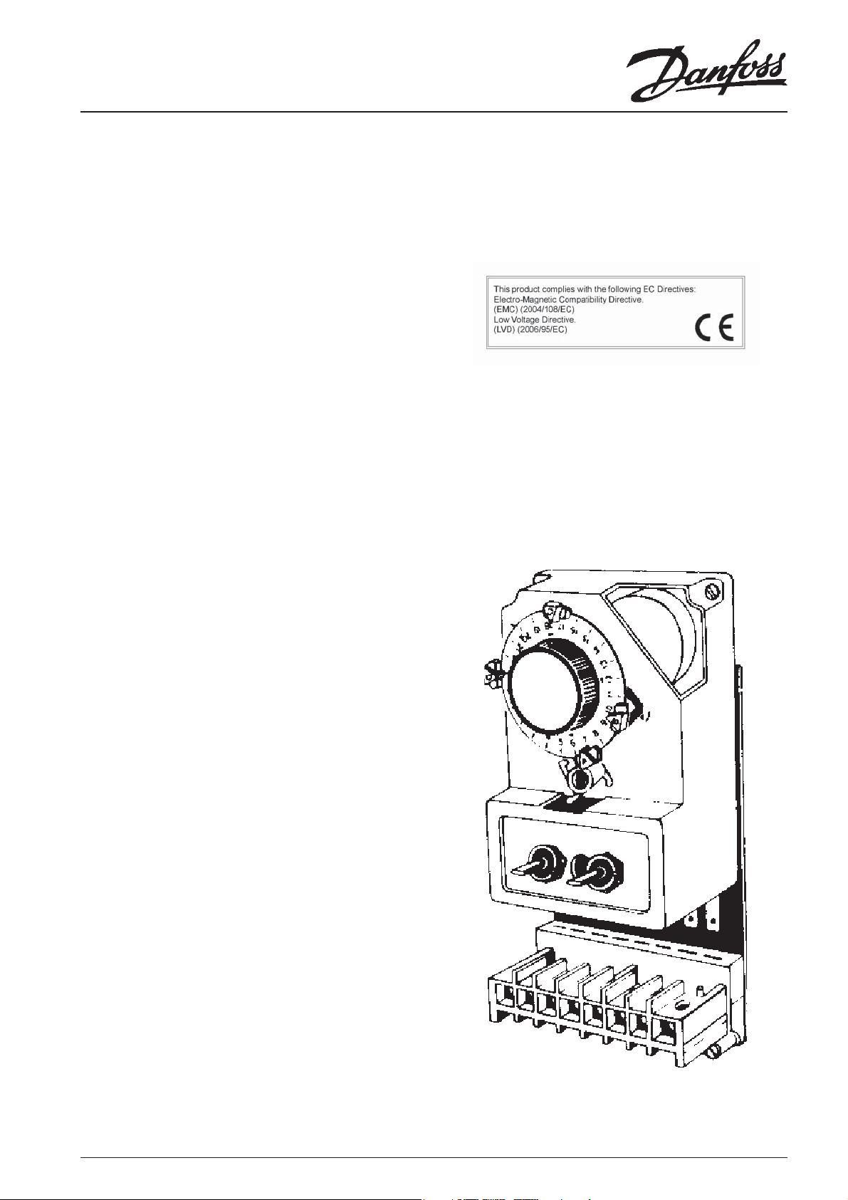
Models 3020P FRU, 3022 FRU, 3060 FRU & 4033 FRU
(For Time Control of Domestic Central Heating Systems)
INSTALLATION INSTRUCTIONS
SPECIFICATION
Power Supply : 220/240Vac, 50 Hz
Switch Action : 3020P & 3022 : 1 x SPST, type 1B
3060 : 2 x SPST, type 1B
4033 : 2 x SPDT, type 1B
Switch Rating : 220/240Vac, 50 Hz, 3(1)A
Timing Accuracy : ± 1 min/month
Enclosure Rating : IP30
Max. Ambient Temperature : 55°C
Designed to meet BS EN60730-2-7
Overall Dimensions : 102mm wide, 210mm high, 60mm deep
Construction : Class 1
Control Pollution Situation : Degree 2
Rated Impulse : 2.5kV
Ball Pressure : 75°C
The unit must be installed by a competent electrician and the installation should conform to IEE Wiring Regulations. The supply to this unit should be
wired through a full disconnect in accordance with BS EN60730-1, ie. one which provides an air gap of at least 3mm in both poles of the mains, e.g. a
13amp plug and unswitched socket, or a switched, fused outlet with neon; either fi tted with a 3amp (max) fuse.
FITTING INSTRUCTIONS
1. Switch off mains supply to programmer/timeswitch.
2. a) Where 3060 programmer is fi tted:
Remove selector switch control knob (pull off ).
b) Where 3020P, 3022, 3033 and 4033 timeswitches
are fi tted:
Remove fi xing rings from selector switches.
3. All models:
Move all four tappet arms to top of dial (12 o'clock position) and
remove outer case.
4. Unscrew the two retaining screws at the top of the module body
holding the module to metal backplate.
5. Unplug module form backplate and terminal block (pull upwards).
6. Plug in new module unit and refi t in reverse order to the above;
taking care not to overtighten the two screws holding the module
to the backplate.
NOTE: IF 4033 MODULE IS TO REPLACE 3033 UNIT:-
a) Transfer all cables in terminal 1 to terminal 7.
b) Link terminal 1 to terminal 6 with insulated mains cable. Then put
4033 module onto the backplate.
7. Fit new outer case.
8. Adjust the four tappet arms to the times required, and reset the
time dial to the correct time of day.
Remember : Red tappets A and C switch ON
Blue tappets B and D switch OFF
9. Turn dial assembly one complete revolution to ensure correct
switching sequence.
10. Switch on mains supply and re-check the operation of the system,
on each selection of the programmer/timeswitch.
11. If a fault still exists it is probable that this will be due to another
component in the system eg:- boiler control, pump, room thermostat,
wiring etc.
In these circumstances we would recommend that you contact your
heating engineer or qualifi ed electrician to check the installation.
1
Page 2
Factory Replacement Units
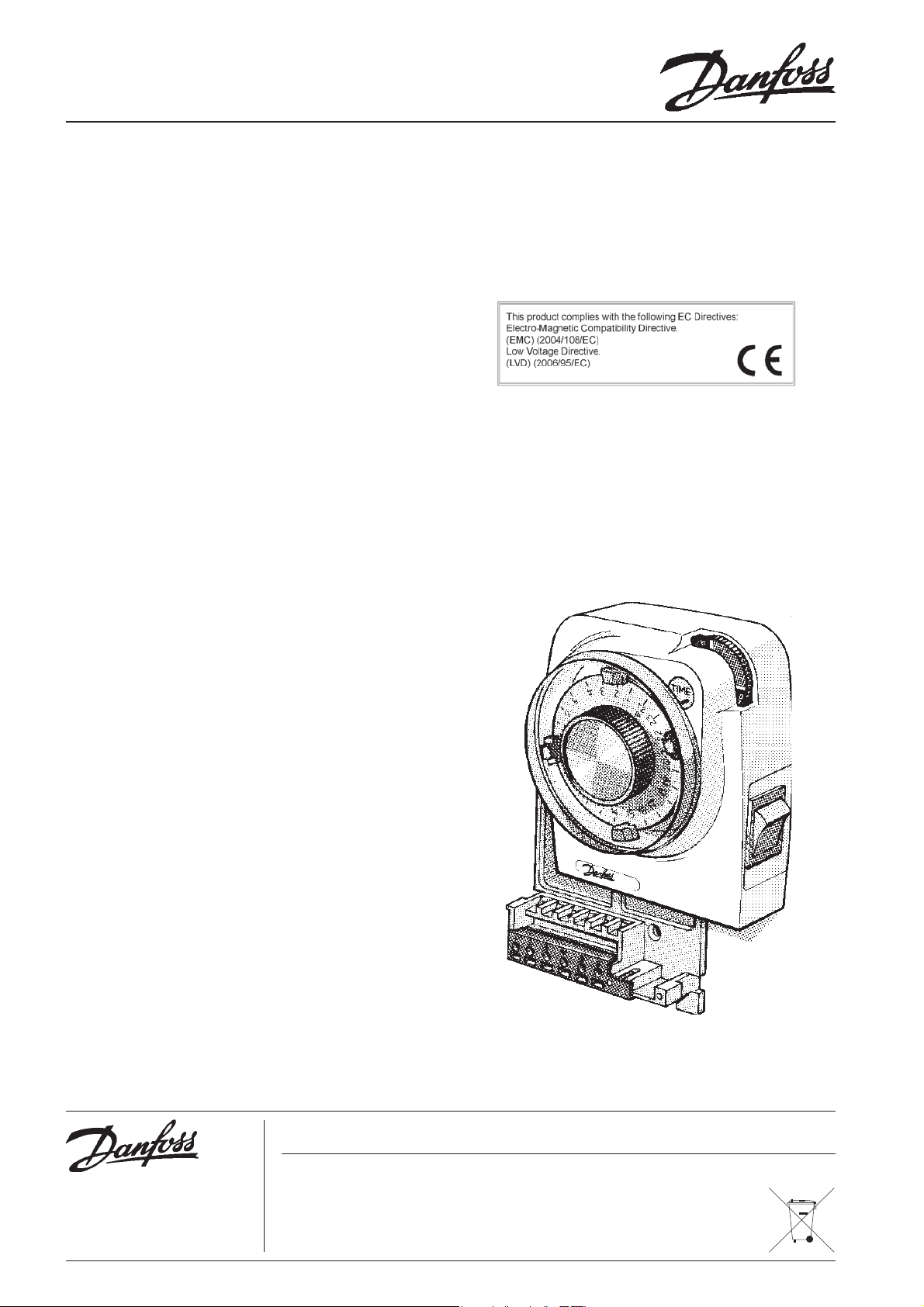
Models 102 FRU and 103 FRU
(for time control of Domestic Central Heating systems)
INSTALLATION INSTRUCTIONS
SPECIFICATION
Power Supply : 220/240Vac, 50 Hz
Switch Action : 1 x SPST, type 1B
Switch Rating : 220/240Vac, 50 Hz, 6(2)A
Timing Accuracy : ± 1 min/month
Enclosure Rating : IP30
Max. Ambient Temperature : 55°C
Designed to meet BS EN60730-2-7
Overall Dimensions : 106mm wide, 135mm high, 63mm deep
Construction : Class II
Control Pollution Situation : Degree 2
Rated Impulse : 2.5kV
Ball Pressure : 75°C
The unit must be installed by a competent electrician and the installation should conform to IEE Wiring Regulations. The supply to this unit should be
wired through a full disconnect in accordance with BS EN60730-1, ie. one which provides an air gap of at least 3mm in both poles of the mains, e.g. a
13amp plug and unswitched socket, or a switched, fused outlet with neon; either fi tted with a 3amp (max) fuse.
FITTING INSTRUCTIONS
1. Switch off mains supply to timeswitch/mini-programmer.
2. Remove fi xing screw in the base of the unit to release the grey plastic
wiring cover.
3. Holding the unit clockface, push upwards to release the module
from wiring backplate.
4. Plug in new module, press down until it locates solidly. Replace grey
cover and fi xing screw. Ensure thumbwheel is in place.
5. Adjust the four tappet arms to the times required, and reset the time
dial to the correct time of day
Remember: Red tappets A and C switch ON
Blue tappets B and D switch OFF
6. Turn dial assembly one complete revolution to ensure correct
switching sequence.
7. Switch on mains supply and re-check the operation of the system,
on each selection of the programmer/timeswitch.
8. I f a fault still exists it is probable that this will be due to another component in the systems eg:- boiler control, pump, room thermostat,
wiring etc.
In these circumstances we would recommend that you contact your
heating engineer or qualifi ed electrician to check the installation.
Danfoss Randall can accept no responsibility for possible errors in catalogues, brochures and other printed material, and reserves the right to alter its products without notice. This also applies to
products already on order provided that such alterations can be made without subsequent changes being necessary in speci cations already agreed.
Danfoss Randall Ltd.,
Ampthill Road
Bedford, MK42 9ER
Telephone: 0845 1217 400 Fax: 0845 1217 515
Email: danfossrandall@danfoss.com
Website: www.danfoss-randall.co.uk
2
Part No. 7498 Iss.9 05/05
 Loading...