

Page 1

VLT® MICRO
Danfoss can accept no responsibility for possible errors in catalogs, brochures and other printed material. Danfoss reserves the right
to alter its products without notice. This also applies to products already on order provided that such alterations can be made
without subsequential changes being necessary in specifications already agreed.
Table of Contents
Chapter 1 Introduction
Getting Started .................................................................................1
Receiving, Inspection, and Storage ................................................... 2
Nameplate Information ..................................................................... 2
General Technical Data .....................................................................3
Specifications ................................................................................... 6
External Parts and Labels ................................................................. 7
Chapter 2 Installation and Wiring
Installation Requirements .................................................................. 8
Wiring ...............................................................................................9
Main Circuit Standard Wiring Chart ................................................. 10
Control Terminal Designations (Factory Settings) ............................. 11
Safety Precautions.......................................................................... 12
Chapter 3 Digital Keypad/Display Operation
Digital Keypad/Display Features...................................................... 14
Quick Set-up .................................................................................. 16
Operation ....................................................................................... 18
Chapter 4 Description of Parameters .............................................................. 20
Chapter 5 Summary of Parameters .................................................................62
Chapter 6 Troubleshooting and Fault Information ............................................ 69
Appendix A Dimensions ..................................................................................... 73
Appendix B Accessories .................................................................................... 75
Appendix C CE Labeling ....................................................................................77
Appendix D Serial Communication ..................................................................... 82
Document Version Number 3.10
Software Version 1.06
VLT is a registered Danfoss trade mark
Page 2

VLT® MICRO
Page 3

VLT® MICRO
Chapter 1
Introduction
Congratulations on your purchase of a VLT® Adjustable Frequency Drive. The VLT
®
MICRO is a high-performance / low noise general-purpose drive, manufactured using
the highest quality components and incorporating the latest micro-processor technology
and control algorithms.
The purpose of this chapter is to provide specific yet simple information to unpack,
install, and operate the drive. This chapter contains information on the following:
• Getting Started
• Unpacking, Inspection, and Storage
• Nameplate Information
• Identification of Parts
Getting Started
This manual will help in the installation, parameter setting, troubleshooting, and daily
maintenance of the AC drive. To guarantee safe operation of the equipment, read the
following safety guidelines before connecting the Adjustable Frequency Drive to AC
Power.
The VLT Adjustable Frequency Drive (AFD) contains dangerous voltages
when connected to line voltage. After disconnecting from the line wait at
least one minute before touching any electrical components. Also make
sure that other voltage inputs have been disconnected, such as external 24
VDC, load-sharing (linkage of DC intermediate circuit), as well as the motor
connection for kinetic back-up. Only a competent electrician should carry
out the electrical installation. Improper installation of the motor or the AFD
may cause equipment failure, serious injury or death. Follow this manual,
National Electrical Codes (NEC
®
) and local safety codes.
Electrostatic Precaution; Electrostatic discharge (ESD). Many electronic
components are sensitive to static electricity. Voltages so low that they
cannot be felt, seen or heard, can reduce the life, affect performance, or
completely destroy sensitive electronic components. When performing
service, proper ESD equipment should be used to prevent possible damage
from occurring.
It is the responsibility of the user or the person installing the AFD to provide
proper grounding, as well as motor overload and branch circuit protection
according to the National Electrical Code (NEC
®
) and local codes.
WARNING
WARNING
CAUTION
1
Page 4

VLT® MICRO
Receiving, Transporting, Inspecting, and Storage
This VLT
®
MICRO Adjustable Frequency Drive has gone through rigorous quality control
tests at the factory before shipment. After receiving and before transporting the drive,
check for the following.
Receipt
After receiving the AC drive, inspect the unit to insure it was not damaged during
shipment.
Transportation
Climatic condition : Class 2K3
Inspection
• After unpacking the unit, make sure that the package includes a drive unit and the
Instruction Manual.
• Make sure that the part number indicated on the nameplate and packing carton
corresponds with the part number of your order.
Storage
The AFD should be kept in the shipping carton before installation. In order to retain the
warranty coverage, the drive should be stored properly. Some storage
recommendations are:
• Store in a clean, dry place
• Store within an ambient temperature range of -20°C to +65°C
• If possible, store in an air-conditioned evironment where the relative humidity is less
than 95%, non-condensing.
• Do not store the unit in places where it could be exposed to corrosive gases.
• Do not store the unit on an unstable surface where it could be damaged by falling to
the floor.
Nameplate Information
Example for 1HP 240V AC Adjustable Frequency Drives
Description of Serial Number
1234 01 H 260
Production date:
week, year
Place of production
Series number
Serial number
MODEL : 176F7304 S. N. 123401H260
INPUT : 3PH 200-240V 50/60 Hz 6.3A
OUTPUT : 3PH 0-240V 5.0A 1.9KVA 1HP
Freq. Range: 0.1-400Hz
Model, Serial Number
Input Spec.
Output Spec.
Freq. Range
Tracking number
Part Numbers:
1/2HP 230V single phase 176F7300
1HP 230V single phase 176F7301
2HP 230V single phase 176F7302
1/2HP 230V three phase 176F7303
1HP 230V three phase 176F7304
2HP 230V three phase 176F7305
1/2HP 230V single phase CE 176F7306
1HP 230V single phase CE 176F7307
2HP 230V single phase CE 176F7308
2
Page 5

VLT® MICRO
General Technical Data
AC line supply (L1, L2, L3):
Supply voltage 200-240 V units ............................ 1 x 200/208/220/230/240 V ±10%
Supply voltage 200-240 V units ............................ 3 x 200/208/220/230/240 V ±10%
Supply frequency .......................................................................................... 50/60 Hz
Max. imbalance of supply voltage .................................... ±2% of rated supply voltage
Power factor/cos ϕ ............................................................................0.90/1.0 at rated load
Max short circuit rating ..................................................................................... 5000 A
VLT output data (U, V, W):
Output voltage ..................................................................... 0-100% of supply voltage
Output frequency..................................................................................... 0.1 - 400 Hz
Rated motor voltage, 200-240 V units ................................... 200/208/220/230/240 V
Rated motor frequency ................................................................................. 50/60 Hz
Switching on output...................................................................................... Protected
Ramp times ............................................................................................. 0.1-600 sec.
Torque characteristics:
Starting torque.................................................................................... 150% for 1 min.
Acceleration torque ............................................................................................ 100%
Overload torque, 200-240 V ............................................................... 150% for 1 min.
Control card, digital inputs:
Number of programmable digital inputs ..................................................................... 6
Terminal nos. ....................................................................... M0, M1, M2, M3, M4, M5
3
Page 6

VLT® MICRO
Control card, analog inputs:
No. of programmable analog inputs (selectable voltage or current) ............................ 1
Terminal numbers ................................................................................................. AV 1
Voltage level .............................................................................................. 0 - 10 VDC
Input resistance, R
i
..........................................................................................................................................
approx. 47 kΩ
Current range ................................................................................................ 4-20 mA
Input resistance, R
i
..........................................................................................................................................
approx. 250 Ω
Resolution ................................................................................................ 10 bit + sign
Galvanic isolation: All analog inputs are galvanically isolated from the supply voltage.
Control card, 10 VDC supply:
Terminal numbers ................................................................................................ +10V
Max. load .......................................................................................................... 10 mA
Control card, analog outputs:
Number of programmable analog outputs ................................................................. 1
Terminal numbers ................................................................................................. AFM
Voltage range at analog output .................................................................. 0 - 10 VDC
Galvanic isolation: All analog outputs are galvanically isolated from the supply voltage.
PHC output
Number of programmable photocoupler outputs ....................................................... 1
Terminal numbers ...................................................................................... MO1-MCM
Max. output ...................................................................................... -48 VDC, 50 mA
Control card, RS485 serial communication:
Terminal numbers .............................................................................................. RJ-11
4
Page 7

VLT® MICRO
5
Relay outputs:
No. of programmable relay outputs ........................................................................... 1
Terminal numbers .............................................. RA, RC (N.O.) RB, RC (N.C.) (Form C)
Max. terminal load rating ...........................................................120 VAC/28 VDC, 5 A
........................................................................................................... 240 VAC, 2.5 A
Brake resistor terminals:
Terminal numbers ............................................................................................. B1, B2
Cable lengths and cross-sections:
Use 75°C copper wire minimum
Max. motor cable length ...................................................................................... 50 m
Max. cable cross-section for line, motor and brake ......................... 14 AWG (2.0 mm
2
)
Max. cable cross-section for control terminals ................................ 14 AWG (2.0 mm
2
)
Control characteristics:
Frequency range ..................................................................................... 0.1 - 400 Hz
Resolution on output frequency .......................................................................±0.1 Hz
Speed, control range (open loop) ............................................. 1:20 of synchro. speed
Speed, accuracy (open loop) .............................................< 1800 rpm: max. error 2%
......................................................... > 1800 rpm: max. error of 0.5% of actual speed
Environment:
Enclosure .............................................................................. Protected chassis (IP20)
Vibration test ...................................................... 1.0 g less than 20Hz, 0.6 g 20-50Hz
Max. relative humidity ................................................ less than 90% (non-condensing)
Ambient temperature ............................................................................ –10°C - +50°C
Temperature during storage/transport ....................................................... –20 - +60°C
Max. altitude above sea level ............................................................ 3300 ft. (1000 m)
Page 8

VLT® MICRO
6
AC Line 1Ø and 3Ø, 200 - 240 Volt
VLVL
VLVL
VL
T OrT Or
T OrT Or
T Or
der Number 1Øder Number 1Ø
der Number 1Øder Number 1Ø
der Number 1Ø
176F7300176F7300
176F7300176F7300
176F7300
176F7301176F7301
176F7301176F7301
176F7301
176F7302176F7302
176F7302176F7302
176F7302
3Ø3Ø
3Ø3Ø
3Ø
176F7303176F7303
176F7303176F7303
176F7303
176F7304176F7304
176F7304176F7304
176F7304
176F7305176F7305
176F7305176F7305
176F7305
1Ø CE1Ø CE
1Ø CE1Ø CE
1Ø CE
176F7306176F7306
176F7306176F7306
176F7306
176F7307176F7307
176F7307176F7307
176F7307
176F7308176F7308
176F7308176F7308
176F7308
Output current
continuous (200-240) [A] 2.5 5.0 7.0
intermittent (200-240) [A] 3.7 7.5 10.5
Output
continuous (200-240) [KVA] 1.0 1.9 2.7
Typical shaft output [HP] 0.5 1.0 2.0
[kW] 0.4 0.75 1.5
Max. motor cable size [AWG] 14 14 14
[mm
2
]222
Max. input current 1Ø, 200-240 [A] 6.3 11.5 15.7
3Ø, 200-240 [A] 2.9 6.3 8.8
Max. power cable size [AWG] 14 14 14
[mm
2
]222
Max. pre-fuses
1)
1Ø [A] 10 20 25
3Ø [A] 10 20 25
Enclosure Chassis (IP20)
Weight 1Ø [lbs.] 1.75 2.0 2.25
3Ø [lbs.] 1.75 1.75 2.0
1)
200-240 VAC; Bussmann type JJN or exact equivalent
Specifications
Page 9

VLT® MICRO
1: Mounting screw holes
2: Nameplate label
3: Bottom cover
4: Digital keypad
5: Upper cover
6: Ventilation hole
7: Input terminals
8: External input/output
terminals
9: B1, B2 External brake
resistor terminals
10: U, V, W Output terminals
7
7
8
9
10
U V W B1 B2
R S T
5
4
3
6
1
2
Page 10

VLT® MICRO
Air
Flow
5 in.
(120mm)
min.
5 in.
(120mm)
min.
2 in.
(50mm)
min.
2 in.
(50mm)
min.
Chapter 2
Installation and Wiring
Chapter 2 provides the information needed to properly install and wire the AC motor
drive. Make sure that the AC drive is wired according to the instructions contained in
this chapter. The instructions should be read and understood before the actual
installation begins. This chapter contains the following information:
• Installation Requirements
• Wiring
Installation Requirements
Install the drive vertically to provide proper ventilation. Adequate space is required
between the drive and a wall or other equipment. The figure below shows the minimum
space needed.
The AC motor drive should be installed in an environment that is:
• protected from rain or moisture
• protected from direct sunlight
• protected from corrosive gases or liquids
• free from airborne dust or metallic particles
• free from vibration
• free from magnetic noise
• Climate condition : Class 3K3 (temperature between -10°C to 50°C, Operation
above 40°C requires good ventilation to avoid over-heating.)
6 in
(150mm)
min.
6 in
(150mm)
min.
8
Page 11

VLT® MICRO
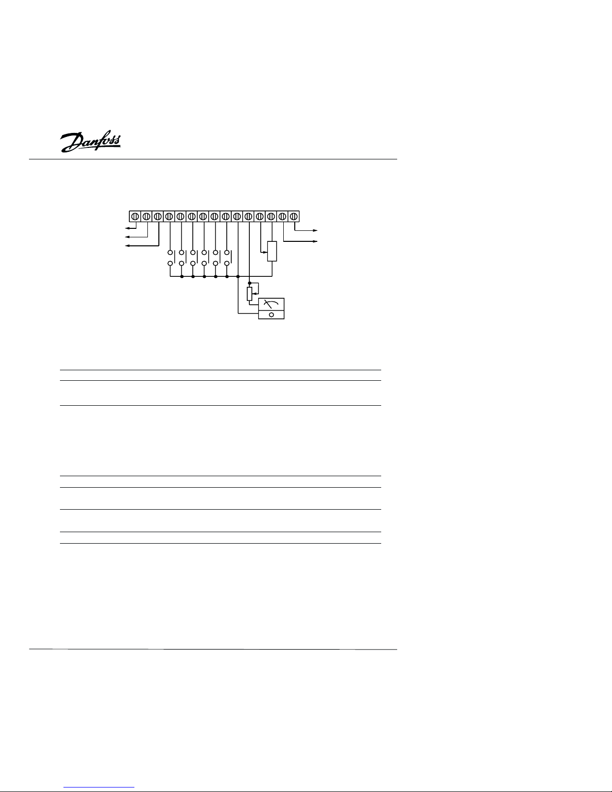
Wiring
There are two wiring systems in an AFD: Main Circuit and Control Circuit. The Main
Circuit terminals are located at the top of the drive. Control Circuit terminals are located
bottom of drive, Both terminal blocks are covered by the plastic housing. Lift the
hinged portion of the housing to gain access to the terminals. Make sure power is
removed before making any connections. Connect wires to the terminals according to
the diagram below. When no connections are made to the control terminals, the drive is
operated by the Digital Keypad/Display.
9
Braking Resistor (Option)
Select 80 ohm 120V
/200 ohm 120V
R
S
T
VAC Input
(Select two
terminals as
input for 230V
single phase
models)
Factory set as
multi-function input terminals
Forward/Stop
Reverse/Stop
Reset
Multi-Step 1
Multi-Step 2
Multi-Step 3
Signal Common
M0
M1
M2
M3
M4
M5
GND
M
Grounding
Trim (1K ohm)
Analog +
output
DC 0-10V –
Factory set as,
Indication of output frequency
Multi-function indication output
contacts 120VAC/28VDC 5A
240VAC 2.5A
Factory set as,
Indication of fault
RA
RB
RC
Multi-function PHC output
48V 50mA below
Factory set as,
Indication of "At work"
MO1
MCM
Power for
speed setting
+10V 10mA (max)
AV1
GND
Output Freq. determined
Analog voltage
0-10VDC
VR: 3K-5K ohm
Analog current
4-20mA
Factory set as, output frequency
determined by the potentiometer on
the control panel
R
S
T
E
U
V
W
F
AFm
GND
Ground
Control Circuit Terminals
Main Circuit (power) Terminals
RJ-11 communication port with
RS-485 serial interface
2: GND
3: SG–
4: SG+
5: +5V
6
* NOTE: Do not plug a modem or telephone in to the RS485 port. Do not use terminals
2 or 5 when using the port.
Page 12

VLT® MICRO
Recommended Input Fuses
BUSSMAN Type JJN
Fuse
VLT MICRO model176F7300 JJN-10
VLT MICRO model176F7301 JJN-20
VLT MICRO model176F7302 JJN-25
VLT MICRO model176F7303 JJN-10
VLT MICRO model176F7304 JJN-20
VLT MICRO model176F7305 JJN-25
VLT MICRO model176F7306 JJN-10
VLT MICRO model176F7307 JJN-20
VLT MICRO model176F7308 JJN-25
10
NOTE:
1. Main-circuit terminals spec. is M3.
2. Main-circuit wiring is 600V 14AWG max.
3. Wiring between drive and motor should
not exceed 330 ft. (100m)
(1) 100 ft. (30m) below, the PWM carrier
frequency should be 15kHz below.
(2) 165 ft. (50m) below, the PWM carrier
frequency should be 10kHz below.
(3) 300 ft. (100m) below, the PWM carrier
frequency should be 5kHz below.
4. Voltage drop (V) = √3 • line resistance
(Ω.Km) • line lengfh (m) • Current (A) • 10
-3
Connection for optional brake resistor.
Refer to Appendix for model numbers.
R S T
U
V
W
B1 B2
200-240 V200-240 V
200-240 V200-240 V
200-240 V
AC unitsAC units
AC unitsAC units
AC units
Page 13
VLT® MICRO
RA
M01MCM+10VAVIAFMGND
M5M4M3M2M1M0RCRB
Relay contactor output
Factory setting:
Forward / Stop
Reverse / Stop
Reset
Multi-step speed 1
Multi-step speed 2
Multi-step speed 3
Photo coupler output
Factory set: Operation
Speed: 3K-5K
Trim potentiometer
VR:1K-5K
Freq. meter
0-10VDC
Full scale voltmeter
Control Terminal Designations
AWG 12-14
Torque 4 kg-cm
Terminal symbol Terminal name Remarks
RA - RC Multi-function output contact Refer to P46,
RB - RC Multi-function output contact Relay Output Contact
M0 - GND Multi-function input 1 Refer to P38, 39, 40, 41, 42
M1 - GND Multi-function input 2
M2 - GND Multi-function input 3
M3 - GND Multi-function input 4
M4 - GND Multi-function input 5
M5 - GND Multi-function input 6
MO1 - MCM Multi-function PHC output 1 Refer to P45
+10V - GND Power supply for speed control Command for power supply
(+10 V)
AVI - GND Analog voltage freq. command 0 - 10V or 4 - 20mA
inputs (10V and 20mA = max. freq.)
AFM - GND Analog frequency/current meter 0 - 10 V output ( 10 V = max. freq.)
Note : Use twisted-shielded or twisted-pair shielded wires for the control signals. It is
recommended to run all signal wiring in a separate steel conduit. The shield wire should
only be connected to ground at the drive end of the cable.
11
Page 14
VLT® MICRO
Installation Notes:
• Make sure that the appropriate input fusing with specified current ratings are
connected between the AC Power Line and the AC drive. A MCC (contactor with
magnetic trip) is recommended between the drive and circuit breaker to provide a
means to disconnect the drive from the power line in the event of a fault.
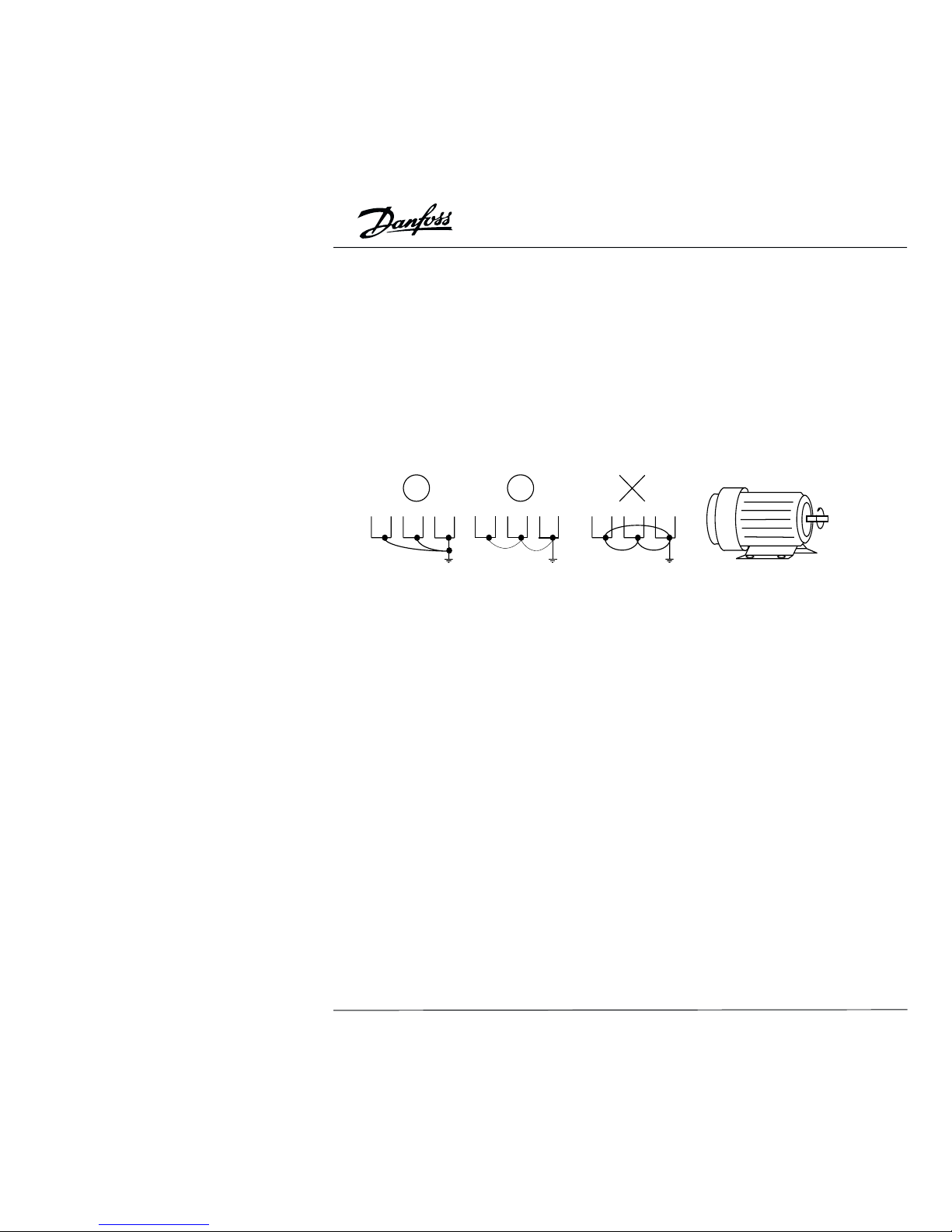
• Make sure that the leads are connected correctly and the drive is properly grounded.
(Ground leads should be at least as the same size as input terminals R, S and T.)
• Use ground leads that comply with AWG standards. Make the length of these ground
leads as short as possible.
• Should several units be installed side by side, all the units should be grounded directly
to the ground terminal. Do not form a loop with the ground leads.
Forward
running
• When the drive output terminals U, V, and W are connected to the motor terminals U,
V, and W, respectively, the motor will rotate counter-clockwise (viewed from the shaft
of the motor as shown above) when a forward operation command is received ( FWD
lamp is ON).
• Make sure that the power source supplies the correct voltage and is capable of
supplying the required current to the drive.
• When power is applied to the drive, the internal DC bus charge indicator LED will be
on.
• Do not attach or remove wiring or connectors when power is applied to the drive. Do
not attempt to probe signals on the circuit board while the drive is operating.
• For single phase applications, the AC input line can be connected to any two of the
three input terminals R, S, T. Note: The drive is not intended for use with single-phase
motors.
• To reverse the direction of rotation, interchange the connection of any of the two
motor leads.
• Do not connect the AC input to any of the U, V, W terminals, as this will damage the
drive.
12
Page 15

VLT® MICRO
• Avoid loose wiring and possible shorts. Tighten all screws on AC circuit terminals
securely.
• It is a good practice to maintain a 90° angle between wires connected to the AC
circuit terminals and wires connected to the control terminals.
• Use shielded cables for Control Circuit wiring,
• Use conduit for the AC power line. The conduit on both the input and output of the
power line should be grounded.
• If an EMI filter is required, it should be located close to the drive. Reducing carrier
frequency can also be a way to reduce EMI noise, however audible noise from the
motor will increase.
• An L-Filter can be added to the U.V.W. side of AC Motor Drives if needed. Do not use
a Capacitor, or L-C Filter (Inductance-Capacitance), or R-C Filter (ResistanceCapacitance).
• A “Ground Fault Interrupt Circuit” can be used. To avoid malfunctioning of the motor
and drive, sensitivity of the current sensor should not be less than 200 mA with a
response time not less than 0.1 second.
13
Page 16

VLT® MICRO
Chapter 3
Digital Keypad/Display Operation
Chapter 3 describes the various controls and indicators found on the Digital Keypad/
Display. The information in this chapter should be read and understood before
performing the start-up procedures described in Chapter 4.
• Description of the Digital Keypad/Display
• Description of Display
• Digital Keypad Operating Modes & Programming Steps
Description of the Digital Keypad/Display
Operating Modes and Functions
When delivered from the factory, the Digital Keypad/Display module is mounted on the
front panel of the AC drive. This module has two functions: display and control. The
Display shows the current status of the drive. The control function provides the
programming interface.
RUN
STOP
FWD
REV
MODE
RUN
ENTER
STOP
RESET
FREQ SET
50
100
0
LED Display
Indicates frequency, motor
parameter setting value and
alarm contents.
Program / Function Data Key
Selects normal mode / program mode.
Displays the motor drive status, such
as output freq., selects the parameters,
FWD/REV or output current, etc.
ENTER Key
Sets the different parameters
LED Indication
Lamp lights during RUN,
STOP, FWD & REV operation.
RUN Key
Starts inverter drive operation.
STOP/RESET Key
Stops and resets the parameter
after faults occur.
UP and DOWN Key
Sets the parameter number or
changes the numerical data
such as the freq. reference.
VR for Setting Freq.
Could be the main-freq. input by
setting parameter Pr.00.
14
Page 17

VLT® MICRO
Function / Program
Pressing the “mode” key repetitively displays the AFD status such as the
reference frequency, output frequency, direction or output current and
selects the parameter setting mode.
Enter
Pressing the “ENTER” key to enter the data change mode and again to
store the value in memory.
Run
Used to start the AC drive operation. This key has no effect when the
drive is controlled by the External Control Terminals.
Stop / Reset
Used to stop AC drive operation. If the drive has stopped due to a fault,
clear the fault first, then press this key to reset the drive. This key has no
effect when the drive is controlled exclusively by the External Control
Terminals.
Up / Down
Press the “Up” or “Down” keys momentarily to change parameter
settings. These keys may also be used to scroll through different operating
values or parameters. Pressing the “Up” or “Down” key momentarily, will
changes the parameter settings in single-unit increments. To quickly run
through the range of settings, press down
and hold the key.
Press the "Up" or "Down" key momentarily to select Forward or Reverse
directions when in Direction Mode and the drive is controlled by the digital
control panel.
MODE
ENTER
RUN
STOP
RESET
RUN
STOP
FWD
REV
Green lamp lights during REV operation.
Green lamp lights during FWD operation.
Red lamp lights by pressing STOP.
Green lamp light by pressing RUN.
Explanation of the LED Indicators
15
Page 18

VLT® MICRO
Quick Set-up
Refer to the relevant chapters of this manual for detailed instructions to configure the
VLT MICRO for your specific requirements.
Before you start, please read the safety instructions in Chapter 1 of this
manual. The adjustable frequency drive contains dangerous voltages when
connected to the AC line. Improper connection of the motor or the VLT
MICRO may cause equipment failure, serious injury or death.
Follow the directions in this Quick Set-up, as well as all local and national safety codes.
Electrical Installation, Power
Connect the AC line and motor cables as shown in Chapter 2 of this manual.
Programming
The VLT adjustable frequency drive is programmed by
means of the Digital Keypad. Refer to Chapter 3 for the
keypad functions.
In order to operate in Quick set-up the Pin Header/Jumpers
(located next to the input terminals) should be as shown.
NOTE:
Speed reference is controlled by the "Arrow" keys. If the
potentiometer is to be used as the speed reference
parameter Pr.00 will need to be programmed to d01.
Set the following parameters according to the motor
nameplate:
Max motor frequency Parameter Pr.04
Max motor voltage Parameter Pr.05
Motor rated current Parameter Pr.52
Motor Full Load Amps
Drive's Max. Cont. Amps
Set the ramp times:
Accel time Parameter Pr.10
Decel time Parameter Pr.11
Motor Start
Press the "RUN" key to start the motor. Adjust desired speed using the "Arrow" keys.
RUN
STOP
FWD
REV
MODE
ENTER
RUN
STOP
RESET
FREQ SET
50
100
0
Pr.52 = x 100
Drive's Max Continuous Amps
Model Amps
176F7300 & 176F7303 2.5
176F7301 & 176F7304 5.0
176F7302 & 176F7305 7.0
J5
J6
J7
16
Page 19

VLT® MICRO
Explanation of Displayed Messages
Displays the AC drives output frequency. The frequency may be
determined by any one of the frequency sources that is selected by
the [Master frequency setting] or [Jog Frequency] command. It may
also be set using the [Multi-step speed setting 1 - 7] as determined by
the inputs to Multi-function Input terminals 1, 2 and 3.
If the frequency source originates from the control panel, the user
can use either the "up" or "down" key to select the frequency.
Displays the output frequency present at terminals U, V, and W.
Displays the custom unit (v), where v = H x Pr.-65.
Displays the internal counter value (C).
Note : Refer to Chapter 5, Pr.-45, 46, 64 - 66 for detailed description.
Displays the custom unit (v), where v = H x Pr.-65.
Displays the custom unit (r), where r = H x Pr.-65.
Displays the custom unit (L), where L = H x Pr.-65.
Displays the custom unit (%), where % = H x Pr.-65.
Displays the counter value (c).
Displays the output current present at terminals U, V, and W
Displays the internal PLC process step currently being performed.
Displays the specified parameter.
Displays the actual value stored within the specified parameter.
AC drive forward run status.
AC drive reverse run status.
The display will read “end” (as shown in the display to the left) for
approximately 1 second if an input has been accepted. After a
parameter value has been set, the new value is automatically stored in
memory. To modify an entry, use the "up" and "down" keys.
The display will read “Err”, if as input is not accepted, or a parameter
value is selected outside the limit of the parameter.
17
Page 20

VLT® MICRO
Press keys
to select the
parameter value.
Press keys
to select the
parameter number.
RUN
STOP
FWD
REV
MODE
ENTER
RUN
STOP
RESET
FREQ SET
50
100
0
• Operating The Digital Control Panel
RUN
STOP
FWD
REV
MODE
ENTER
RUN
STOP
RESET
FREQ SET
50
100
0
RUN
STOP
FWD
REV
MODE
ENTER
RUN
STOP
RESET
FREQ SET
50
100
0
RUN
STOP
FWD
REV
MODE
ENTER
RUN
STOP
RESET
FREQ SET
50
100
0
RUN
STOP
FWD
REV
MODE
ENTER
RUN
STOP
RESET
FREQ SET
50
100
0
Press to set
the motor running
frequency
Note: Set parameter Pr.00 to d00 to enable setting the frequency by the keypad.
RUN
STOP
FWD
REV
MODE
ENTER
RUN
STOP
RESET
FREQ SET
50
100
0
RUN
STOP
FWD
REV
MODE
ENTER
RUN
STOP
RESET
FREQ SET
50
100
0
Press the freq.
will decrease
3.5Hz/sec.
RUN
STOP
FWD
REV
MODE
ENTER
RUN
STOP
RESET
FREQ SET
50
100
0
Press the freq.
will increase 3.5Hz/
sec.
RUN
STOP
FWD
REV
MODE
ENTER
RUN
STOP
RESET
FREQ SET
50
100
0
RUN
STOP
FWD
REV
MODE
ENTER
RUN
STOP
RESET
FREQ SET
50
100
0
• Operate the parameter value setting.
RUN
STOP
FWD
REV
MODE
ENTER
RUN
STOP
RESET
FREQ SET
50
100
0
RUN
STOP
FWD
REV
MODE
ENTER
RUN
STOP
RESET
FREQ SET
50
100
0
RUN
STOP
FWD
REV
MODE
ENTER
RUN
STOP
RESET
FREQ SET
50
100
0
RUN
STOP
FWD
REV
MODE
ENTER
RUN
STOP
RESET
FREQ SET
50
100
0
RUN
STOP
FWD
REV
MODE
ENTER
RUN
STOP
RESET
FREQ SET
50
100
0
Displays the
parameter
number
automatically.
Press
Key
MODE
MODE
Press
Key
MODE
Press
Key
MODE
Press
Key
MODE
Press
Key
ENTER
Press
Key
Press
Key
ENTER
Press
Key
Press
Key
Press
Key
and
hold
Press
Key
and
hold
Release
Key
• Indicate the operation mode.
Indication after
power on.
Parameter value
setting motor.
Output frequency
monitor.
Output current
monitor.
Fwd./Rev.
monitor.
Displays the frequency
setting monitor.
Parameter value
setting motor.
The setting
value monitor
Modified the Pr.
value to d01.
The setting
value is right.
Parameter
setting monitor.
"End" The new value has
been automatically
stored in the
internal
memory.
"Err" The value entered
is not correct.
Frequency value
setting monitor.
Setting the freq.
to 59.9Hz.
Decrease the freq.
to 0Hz approx 17
sec. later.
Increase the freq.
to 60Hz approx
17 sec. later.
The freq. value can
be entered in stop
or operating mode.
18
Page 21

VLT® MICRO
• Change the different indication mode as follows:
RUN
STOP
FWD
REV
MODE
ENTER
RUN
STOP
RESET
FREQ SET
50
100
0
RUN
STOP
FWD
REV
MODE
ENTER
RUN
STOP
RESET
FREQ SET
50
100
0
RUN
STOP
FWD
REV
MODE
ENTER
RUN
STOP
RESET
FREQ SET
50
100
0
RUN
STOP
FWD
REV
MODE
ENTER
RUN
STOP
RESET
FREQ SET
50
100
0
RUN
STOP
FWD
REV
MODE
ENTER
RUN
STOP
RESET
FREQ SET
50
100
0
RUN
STOP
FWD
REV
MODE
ENTER
RUN
STOP
RESET
FREQ SET
50
100
0
RUN
STOP
FWD
REV
MODE
ENTER
RUN
STOP
RESET
FREQ SET
50
100
0
• Reset the fault messages.
RUN
STOP
FWD
REV
MODE
ENTER
RUN
STOP
RESET
FREQ SET
50
100
0
RUN
STOP
FWD
REV
MODE
ENTER
RUN
STOP
RESET
FREQ SET
50
100
0
RUN
STOP
FWD
REV
MODE
ENTER
RUN
STOP
RESET
FREQ SET
50
100
0
RUN
STOP
FWD
REV
MODE
ENTER
RUN
STOP
RESET
FREQ SET
50
100
0
RUN
STOP
FWD
REV
MODE
ENTER
RUN
STOP
RESET
FREQ SET
50
100
0
Press
Key
or
MODE
Press
Key
STOP
RESET
Press
Key
Press
Key
RUN
MODE
Press
Key
MODE
Press
Key
MODE
Press
Key
After
10 sec.
twice
After
10 sec.
STOP
RESET
Press
Key
Fault message
O.H. is displayed.
Frequency setting
will be displayed
after the fault is
removed.
Change to Reverse
oprtation.
Change the Fwd.
or Rev. operation.
Setting the
frequency.
Decrease motor
speed to stop. Stop mode.
"STOP" "REV"
will light up.
"STOP" "REV" will
light "RUN" will
flash.
"STOP" "FWD"
will light up.
"RUN" "FWD"
will light up.
Indication after
power on.
Operate at
60.0Hz.
Output frequency
monitor.
Output current
monitor.
Forward
operation
monitor.
"RUN" "REV" will light
"FWD" will flash.
19
Page 22

VLT® MICRO
Chapter 4
Description of Parameters
Pr.00 Master Frequency Source Select
Factory Setting d00
Units None
Settings d00 Master frequency determined by keypad digital control.
d01 Master frequency determined by analog signal of DC 0V - +10V,
a. Performed by keypad potentiometer. The pin header and jumper
combined as 1 and 3 in the diagram below.
b. Performed by external terminal AVI. The pin header and jumper
combined as 2 and 3 in the diagram below.
d02 Master frequency determined by analog signal of DC 4mA - 20mA.
Performed by external terminal AVI. The pin header and jumper
combined as 2 and 4 in the diagram below.
Pin Header/Jumper Diagrams:
The pin headers and jumpers are located on the upper right corner of the control board
and can be accessed by opening the input terminal cover.
J5: Selects the source of the potentiometer input from
the External Control Terminal (AVI) or from the
Digital Keypad/Display (LC-03P) potentiometer.
J6, J7: This jumper is used to select the DC voltage signal
or DC current signal for master frequency control.
J5 J6 J7
1
2
3
12
34
J5
J5
J6 J7
J6 J7
1
2
3
1
2
3
1
2
3
1
2
3
External terminal
AV1 effective
Analog current
signal selection
Keypad
VR effective
Analog voltage
signal selection
20
Page 23

VLT® MICRO
Pr.01 Operation Command Source Select
Factory Setting d00
Units None
Settings d00 Operating instructions determined by the Digital Keypad/Display.
d01 Operating instructions determined by the External Control Terminals.
Keypad STOP key is effective.
d02 Operating instructions determined by the External Control Terminals.
Keypad STOP key is not effective.
(Refer to parameters 38, 39, 40, 41 and 42 for more details.)
Pr.02 Motor Stop Method Select
Factory Setting d00
Units None
Settings d00 Ramp stop
d01 Coast to stop
This parameter determines how the motor is stopped when the AC drive receives a valid
stop command.
Ramp: The AC drive output frequency decelerates down to the minimum output
frequency (Pr.08) in the time specified by Pr.11 or Pr.13, then the output is turned off.
Coast: The AC drive output is turned off immediately and the motor free runs until it
comes to a stop.
Ramp Coast
To determine the best method to stop the motor, the type of load needs to be
considered.
1. In many applications operator safety and material processing can be improved when
"Ramp Stop" is selected. The accel./decel. time required will depend on the specific
parameters of your application.
2. The advantage of using "Coast-to-stop" is the motor will heat less during
frequent starting and stopping. Applications where "Coast-to-stop" is commonly
used are fans, pumps, blowers, mixing and agitating.
Frequency command
sec. sec.
Speed
Stop command Setting value Stop command ?
Speed (Free running to stop)
Frequency command
Hz
Hz
21
Page 24

VLT® MICRO
Pr.03, Pr.04, Pr.05, Pr.06, Pr.07, Pr.08, Pr.09 – V / F Curve
Pr.03 Maximum Output Frequency
Factory Setting d60.0 Hz
Units 0.1 Hz
Parameter value d50.0 - d400.0 Hz
This parameter determines the maximum AC drive output frequency. Analog inputs (0 10 V, 4 - 20 mA) are scaled to correspond to the output frequency range.
Pr.04 Motor Frequency
Factory Setting d60.0 Hz
Units 0.1 Hz
Parameter value d10.0 - d400.0 Hz
This value should be set according to rated frequency of the motor as indicated on the
motor nameplate.
Pr.05 Motor Voltage
Factory Setting d220.0
Units 0.1 V
Parameter value d2.0 - d255.0
This parameter determines the Maximum Output Voltage of the AC drive. The maximum
output voltage setting must be smaller than or equal to the rated voltage of the motor as
indicated on the motor nameplate.
Pr.06 Mid-point Frequency
Factory Setting d1.50 Hz
Units 0.1 Hz
Parameter value d0.1 - d400.0 Hz
This parameter sets the Midpoint Frequency of the V/F curve. It may be used to
determine the V/F ratio between the Minimum Frequency and the Mid-point Frequency.
Pr.07 Mid-point Voltage
Factory Setting d12.0 V
Units 0.1 V
Parameter value d2.0 - d255.0
This parameter sets the Midpoint Voltage of the V/F curve. It may be used to determine
the V/F ratio between the Minimum Voltage and the Mid-point Voltage.
22
Page 25

VLT® MICRO
Pr.08 Minimum Output Frequency
Factory Setting d1.50 Hz
Units 0.1 Hz
Parameter value d0.1 - d20.0 Hz
This parameter programs the Minimum Output Frequency of the AC drive.
Pr.09 Minimum Output Voltage
Factory Setting d12.0 V
Units 0.1 V
Parameter value d2.0 - d50.0 V
This parameter programs the Minimum Output Voltage of the AC drive.
Voltage
Pr.05
Pr.07
Pr.09
Pr.08 Pr.06
Pr.04
Pr.03
Frequency
Fan/Pump V/F Curve
Custom V/F Curve
Frequency
Pr.03Pr.04
Pr.06
Pr.08
Pr.05
Pr.07
Pr.09
Voltage
Voltage
Pr.05
Pr.07
Pr.09
Pr.06
Pr.08
Pr.03
Pr.04
Frequency
Standard V/F Curve
0
23
Page 26

VLT® MICRO
Pr.10, Pr.11, Pr.12, Pr.13 Acceleration / Deceleration Time
Pr.10 Acceleration Time 1 (Can be programmed while the drive is running.)
Factory Setting d10.0 Sec
Units 0.1 Sec
Parameter value d0.1 - d600.0 Sec
Commonly Used V/F Pattern Settings
(1) General Purpose
(2) Fans and Pumps
(3) High Starting Torque
Motor Spec 50Hz
Motor Spec 50Hz
Motor Spec 50Hz
Motor Spec 60Hz
Motor Spec 60Hz
Motor Spec 60Hz
No. Set value
Pr.03 50.0
Pr.04 50.0
Pr.05 220.0
Pr.06 1.3
Pr.07 12.0
Pr.08 1.3
Pr.09 12.0
No. Set value
Pr.03 60.0
Pr.04 60.0
Pr.05 220.0
Pr.06 3.0
Pr.07 23
Pr.08 1.5
Pr.09 18.0
No. Set value
Pr.03 50.0
Pr.04 50.0
Pr.05 220.0
Pr.06 25
Pr.07 50.0
Pr.08 1.3
Pr.09 10.0
No. Set value
Pr.03 50.0
Pr.04 50.0
Pr.05 220.0
Pr.06 2.2
Pr.07 23.0
Pr.08 1.3
Pr.09 14
Factory Settings
No. Set value
Pr.03 60.0
Pr.04 60.0
Pr.05 220.0
Pr.06 1.5
Pr.07 10.0
Pr.08 1.5
Pr.09 10.0
No. Set value
Pr.03 60.0
Pr.04 60.0
Pr.05 220.0
Pr.06 30
Pr.07 50.0
Pr.08 1.5
Pr.09 10.0
V
220
23
14
1.3 2.2 60.0
f
1.3 25 50.0
f
1.5 30 60.0
f
1.5 50.0
f
1.5 60.0
f
1.5 3 60.0
f
V
220
50
10
V
220
10
V
220
10
V
220
23
10
V
220
50
10
24
Page 27

VLT® MICRO
This parameter is used to determine the time required for the AC drive to ramp from 0
Hz to its Maximum Output Frequency (Pr.03). The rate is linear unless S Curve is
"enabled". This rate of acceleration applies to any incremental increase in command
frequency unless selected using the Multi-Function Inputs, MI1 - 3. See Parameters 39,
40 and 41. Acceleration time 1 is the default when a Multi-Function Input Terminal has
not been programmed to select between Acceleration time 1 and Acceleration time 2.
Pr.11 Deceleration Time 1 (Can be programmed while the drive is running.)
Factory Setting d10.0 Sec
Units 0.1 Sec
Parameter value d0.1 - d600.0 Sec
This parameter is used to determine the time required for the AC drive to decelerate
from the Maximum Output Frequency (Pr.03) down to 0 Hz. The rate is linear unless S
Curve is "enabled". Deceleration time 1 is the default when a Multi-Function Input
Terminal has not been programmed to select between Deceleration time 1 and
Deceleration time 2.
Note: See Pr.101; Automatic Accel and Decel times are default. Change to "Linear
Acceleration/Deceleration" to enable manual adjustment.
Pr.12 Acceleration Time 2 (Can be programmed while the drive is running.)
Factory Setting d10.0 Sec
Units 0.1 Sec
Parameter value d0.1 - d600.0 Sec
This parameter determines the time required for the AC drive to ramp from 0 Hz to the
Maximum Operating Frequency (Pr.03). The rate is linear unless S Curve is "enabled".
The rate of acceleration applies to any incremental increase in command frequency
unless Acceleration Time 1 (Pr.10) is selected. Acceleration Time 1 and 2 may be
selected using the Multi-Function Inputs M1 - 3. (See Parameters 39, 40 and 41.)
Speed
Time
Decel
Time
Accel
Time
Frequency command
Pr.10 or Pr.12
Pr.11 or Pr.13
25
Page 28

VLT® MICRO
Frequency
S-curve characteristics Time
Time
Time
Pr.14 > d01
"S curve Enabled"
Pr.14 = d00
"S curve Disabled"
Accel time
1 or 2
Decel time
1 or 2
Note: See Pr.101; Automatic Accel and Decel times are default. Change to "Linear
Acceleration/Deceleration" to enable manual adjustment.
Pr.13 Deceleration Time 2 (Can be programmed while the drive is running.)
Factory Setting d10.0 Sec
Units 0.1 Sec
Parameter value d0.1 - d600.0 Sec
This parameter determines the time for the AC drive to decelerate from the Maximum
Output Frequency (Pr.03) down to 0 Hz. The rate is linear unless S Curve is "enabled".
The rate of deceleration applies to any decrease in command frequency unless
Deceleration Time 1 is selected. Deceleration Time 1 and 2 may be selected using the
Multi-Function Inputs M1 - 3. (See Parameters 39, 40 and 41.)
Application Notes:
1. The Accel./Decel. Time is defined as the time required to change the output
frequency from the value of Pr.03 to the value of Pr.08 (Maximum and Minimum
Output Frequencies).
2. The Accel./Decel. time can be calculated by using the parameter values of the
following formula: a = [(Pr.10, 11, 12, 13)(Pr.03 Pr.08)](Pr.03 0 Hz).
3. The actual Accel./Decel. time should be measured to insure it meets the system
requirements.
Pr.14 S-curve
Factory Setting d00 Sec
Units None
Parameter value d00 - d07
This parameter should be programmed during start-up. It is used to provide smooth
acceleration and deceleration. S-curves can be selected from 1 to 7. Settings 1 to 7 are
added to the active accel./decel. times to form an adjustable S-curve.
26
Page 29

VLT® MICRO
Pr.15 Jog Accel. / Decel. Time
(Can be programmed while the drive is running.)
Factory Setting d1.0 Sec
Units 0.1 Sec
Parameter value d0.1 - d600.0 Sec
This parameter, together with the Jog Frequency (Pr.16), determines the time required
for the AC drive to ramp from 0 Hz to the Jog Frequency, or the time required to ramp
from the Jog Frequency to 0 Hz.
Pr.16 Jog Frequency
(Can be programmed while the drive is running.)
Factory Setting d6.00 Hz
Units 0.1 Hz
Parameter value d0.1 - d400.0 Hz
Jog Frequency can be controlled through a Multi-Function Input Terminal: M1 to M5
(See Pr.38 - pr.42). Jog starts from the Minimum Output Frequency (Pr.08) accelerating
to the Jog Frequency (Pr.16) in the time interval set by the Accel./Decel. Time (Pr.15).
Pr.17, Pr.18, Pr.19, Pr.20, Pr.21, Pr.22, Pr.23 – Multi-speed Operation
Multi-Step Speeds 1, 2, 3, 4, 5, 6, 7
(Can be programmed while the drive is running.)
Factory Setting d0.00 Hz
Units 0.1 Hz
Parameter value d0.1 - d400.0 Hz
Multi-step speed Parameters 17 - 23 in conjunction with Parameters 78, 79, 81 - 87
provide multi-step motion control.
Speed
JOG frequency P16
JOG command
ON
OFF
Decel
Time
Pr.15
Accel
Time
Pr.15
Time
27
Page 30

VLT® MICRO
Pr.24 Reverse Run Inhibit
Factory Setting d00
Units None
Settings d00 REV run enabled
d01 REV run disabled
This parameter inhibits AC drive operation in the reverse direction.
Pr.25 Over-voltage Stall Prevention
Factory Setting d01
Units None
Settings d00 Disable over-voltage stall prevention
d01 Enbable over-voltage stall prevention
During deceleration, the DC bus voltage may exceed the maximum amount allowable
due to motor regeneration. When this function is enabled, the AC drive will cease to
decelerate and then maintain a constant output frequency. The drive will only resume
deceleration when the voltage drops below the preset value.
Pr.26, Pr.27 Over-Current Stall Prevention
Pr.26 Over-Current Stall Prevention During Acceleration
Factory Setting d170%
Units 1%
Parameter value d50 - d200%
Over voltage stall prevention
Time
Time
Output
frequency
DC bus
voltage
Over voltage
detection
level
28
Page 31

VLT® MICRO
During periods of rapid acceleration or excessive load, the AC drive output current may
increase abruptly and exceed the value specified by Pr.26. When this function is
enabled, the AC drive will cease to accelerate, then maintain a constant output
frequency. The drive will only resume acceleration when the current drops below the
preset value.
Pr.27 Over-Current Stall Prevention During Operation
Factory Setting d170%
Units 1%
Parameter value d50 - d200%
During steady-state operation with the motor load rapidly increasing, the AC drive output
current may exceed the limit specified in Pr.27. When this occurs, the output frequency
will decrease to maintain a constant motor speed. The drive will accelerate to the
steady-state operating frequency only when the output current drops below the level
specified by Pr.27. A setting of 100% is equal to the rated current of the drive.
Pr.28, Pr.29, Pr.30, Pr.31 – DC Braking Current
Pr.28 DC Braking Current
Factory Setting d00%
Units 1%
Parameter value d00 - d100%
This parameter determines the DC current that will be applied to the motor during
braking when the Motor Stop Method (Pr.02) is programmed to "Ramp Stop". The DC
braking current is set at increments of 1%. A setting of 100% is equal to the rated
current of the drive.
NOTE: When setting this parameter, begin at a lower current level, then increase the
value until sufficient holding torque is achieved. The rated motor current should not be
exceeded.
Output
current
Output
current %
Pr.26
Overcurrent
detection
level
Output
frequency
Time
Time
Stall prevention during acceleration Over-current stall prevention during operation
Time
Time
Output
frequency
Overcurrent
detection
level
Pr.27
29
Page 32

VLT® MICRO
Pr.29 DC Braking Time During Start-up
Factory Setting d0.0 Sec
Units 0.1 Sec
Parameter value d0.0 - d5.0 Sec
This parameter determines the time duration that DC braking current will be applied to
the motor during the AC drive start-up.
Pr.30 DC Braking Time During Stopping
Factory Setting d0.0 Sec
Units 0.1 Sec
Parameter value d0.0 - d25.0 Sec
This parameter determines the time duration that DC braking current will be applied to
the motor when the Motor Stop Method (Pr.02) is set to "Ramp Stop".
Pr.31 DC Braking Start-up Frequency
Factory Setting d0.00 Hz
Units 0.1 Hz
Parameter value d0.0 - d60.0 Hz
This parameter determines the Start-up Frequency for DC braking when the AC drive
starts to decelerate. The frequency may be set in 0.1 Hz increments. When the value is
less than that specified by Pr.08, Minimum Output Frequency, the start-up frequency for
DC braking will be the value specified by this parameter.
Pr.32, Pr.33, Pr.34, Pr.35 – Momentary Power Loss Protection
Pr.32 Momentary Power Loss Operation Mode Selection
Factory Setting d00
Units None
Settings d00 Operation stops after momentary power loss.
d01 Operation continues after momentary power loss. Speed search
starts with the Frequency Reference Value.
Minimum output
frequency
DC brake starting frequency
DC braking current %
Pr.08
Pr.29
Pr.28
Pr.31
Pr.30
30
Page 33

VLT® MICRO
d02 Operation continues after momentary power loss. Speed search
starts with the Minimum Frequency.
NOTE: Fault contact is not energized during restart after a momentary power loss. This
parameter determines the AC drive mode of operation after recovery from a momentary
power loss.
Pr.33 Maximum Allowable Power Loss Time
Factory Setting d2.0 Sec
Units 0.1 Sec
Parameter value d0.3 - d5.0 Sec
During a power failure, if the power loss time is less than the time defined by this
parameter, the AC drive will resume operation. If the Maximum Allowable Power Loss
Time is exceeded, the AC drive output power will be turned off.
Pr.34 Minimum Base Block Time
Factory Setting d0.5 Sec
Units 0.1 Sec
Parameter value d0.3 - d5.0 Sec
When a momentary power loss is detected, the AC drive output turns off for a specified
time interval determined by Pr.34 before resuming operation. This time interval is called
the "Base Block Time". This parameter should be set to a value where the residual
output voltage is nearly zero.
Pr.35 Speed Search Deactivation Current Level
Factory Setting d100%
Units 1%
Parameter value d30 - d200%
Following a power failure, the AC drive will start its speed search operation only if the
output current is greater than the value determined by Pr.35. When the output current is
less than that of Pr.35, the AC drive output frequency is determined to be at a "speed
synchronization" point. The drive will start to accelerate or decelerate back to the
operating frequency at which it was programmed to operate.
INPUT
POWER
OUTPUT
FREQUENCY
OUTPUT
VOLTAGE
Allowable maximum
power loss time
Speed synchronization
detection
OUTPUT
VOLTAGE
OUTPUT
FREQUENCY
INPUT
POWER
Pr.33
Pr.32 = d01
Speed search starts with
the frequency reference value
Pr.34
Min. baseblock
time
Speed
search
operation
Allowable maximum
power loss time
Pr.33
Pr.32 = d0002
Speed search starts with
minimum starting frequency
Pr.34
Min. baseblock
time
31
Page 34

VLT® MICRO
Pr.36, Pr.37 – Reference Frequency: Upper / Lower limit
Pr.36 Reference Frequency Upper Limit
Factory Setting d400.0 Hz
Units 0.1 Hz
Parameter Value d0.1 - d400.0 Hz
This parameter programs the upper limit of the reference frequency in 0.1 Hz
increments.
Pr.37 Reference Frequency Lower Limit
Factory Setting d0.0 Hz
Units 0.1 Hz
Parameter Value d0.1 - d400.0 Hz
Determines the lower limit of the reference frequency in 0.1 Hz increments.
Application Notes:
1. Parameters 36, 37 are provided to prevent damage to the AC motor and applicable
machinery. Under certain conditions a motor can overheat and/or machinery can be
damaged at excessively high speeds.
2. The lower limit for AC drive operation is determined by the greater value of Pr.08
(Minimum Output Frequency) and Pr.37 (Reference Frequency Lower Limit). The
upper limit for AC drive operation is determined by the lesser value of Pr.03
(Maximum Output Frequency and Pr.36 Reference Frequency Upper Limit).
Pr.38 Multi-Function Input Terminals (M0, M1)
Factory Setting d00
Units None
Settings d00 - d02
Pr.39 Multi-Function Input Terminals (M2)
Factory Setting d05
Units None
Settings d03 - d20
Output frequency
Pr.36
Pr.37
Input frequency
32
Page 35

VLT® MICRO
Pr.40 Multi-Function Input Terminals (M3)
Factory Setting d06
Units None
Settings d03 - d20
Pr.41 Multi-Function Input Terminals (M4)
Factory Setting d07
Units None
Settings d03 - d20
Pr.42 Multi-Function Input Terminals (M5)
Factory Setting d08
Units None
Settings d03 - d20
Parameter - Function List:
Value Function Value Function
d00 M0: Fwd./Stop, M1: Rev./Stop d11 1st-2nd Accel./Decel. Time Select
d01 M0: Run/Stop, M1: Fwd./Rev. d12 External Base Block
(Normally Closed)
d02 3-Wire Operation Control Mode d13 External Base Block (Normally Open)
d03 External Fault (Normally Open) d14 Increase Output Frequency Control
d04 External Fault (Normally Closed) d15 Decrease Output Frequency Control
d05 External Reset d16 Run PLC Program
d06 Multi-Step Speed Control 1 d17 Pause PLC Program
d07 Multi-Step Speed Control 2 d18 Counter Trigger
d08 Multi-Step Speed Control 3 d19 Counter Reset
d09 Jog Frequency d20 No Operation
d10 Accel./Decel. Speed Inhibit Control
33
Page 36

VLT® MICRO
Explanation:
1.
d00, d01: Start/Stop/Directional Control – Mode 1 - Two wire control: Parameter value
set to d00 (Pr.38 only).
Mode 2 - Two wire control: Parameter value set to d01 (Pr.38 only).
Mode 3 - Three wire control: Parameter value set to d02 (Pr.38 only).
When value d02 is selected for Pr.38, the program value for Pr.39 will be ignored.
Three Wire Control remains in effect.
2. d03, d04: External Fault – Parameter values d03, d04 programs Multi-Function Input
Terminals: M1 (Pr.38), M2 (Pr.39), M3 (Pr.40), M4 (Pr.41) or (Pr.42) to be External Fault
(E.F.) inputs.
The External Fault input signal has fast priority for display of "E.F." by the Digital
Keypad/Display. All AC drive functions will be stopped and the motor will free-run.
Normal operation can resume after the external fault is cleared and the AC drive is reset.
FWD/STOP
REV/STOP
M0 "Open': Stop; "Close": FWD Run
M1 "Open": Stop; "Close": REV Run
GND
VLT MICRO
M0 "Open': Run; "Close": Stop
M1 "Open": FWD; "Close": REV
GND
VLT MICRO
RUN/STOP
REV/FWD
M0
(Run command, Runs when "Closed")
M2
(Stop command, stops when "Open")
M1
(REV/FWD Run select
VLT MICRO
STOP
RUN
REV/FWD
"Open": FWD Run
"Closed": REV Run)
GND
Mx "Close": Operation available.
Mx "Open": Operation available.
GND
VLT MICRO
Setting by d04
E.F.(N.O)
Setting by d03
E.F (N.C)
34
Page 37

VLT® MICRO
3. d05: External Reset – Parameter value d05 programs a Multi-Function Input
Terminal: M1 (Pr.38), M2 (Pr.39), M3 (Pr.40), M4 (Pr.41) or M5 (Pr.42) to be External
Reset.
External Reset has the same function as the Reset key on the Digital keypad. External
faults O.H., O.C. and O.V. are cleared when this input is used to reset the drive.
4.
d06, 07, 08: Multi-Step Speed Command – Parameter values d06, d07, d08
programs any three of the following Multi-Function Input Terminals: M1 (Pr.38), M2
(Pr.39), M3 (Pr.40), M4 (Pr.41) or M5 (Pr.42) for multi-step speed command function.
These three inputs select the multi-step speeds defined by Parameters 17 - 23 as
shown in the following diagram. Parameters 78 - 87 can also control output speed by
programming the AC drive's internal PLC function.
Mx "Close": Operation available.
GND
VLT MICRO
RESET
Setting by d05
Mx "Closed": Operation available.
Mx "Closed": Operation available.
Mx "Closed": Operation available.
GND
d06 Multi-step 1
d07 Multi-step 2
d08 Multi-step 3
VLT MICRO
P17 STEP 1
P18 STEP 2
P19 STEP 3
P20 STEP 4
P21 STEP 5
P22 STEP 6
P23 STEP 7
Master Freq.
Freq.
Mx 1-GND
Mx 2-GND
Mx 3-GND
Operation Command
ON
ON
ON ON ON
ON ON ON ON
ON ON ON ON
OFF
step 2
step 3
step 4
step 5
step 6
step 7
step 1
Time
35
Page 38

VLT® MICRO
5. d09: Jog Frequency Control – Parameter value d09 programs a Multi-function Input
Terminal: M1 (Pr.38), M2 (Pr.39), M3 (Pr.40), M4 (Pr.41) or M5 (Pr.42) for Jog control.
Jog operation programmed by d09 can only be initiated with the motor stopped (refer
to Pr.15, Pr.16).
6.
d10: Accel./Decel. Speed Inhibit – Parameter d10 programs a Multi-functional Input
Terminal: M1 (Pr.38), M2 (Pr.39), M3 (Pr.40), M4 (Pr.41), M5 (Pr.42) for "hold speed"
control. When the command is accepted, acceleration and deceleration is stopped
and the AC drive maintains the motor at a constant speed.
7.
d11: First or Second Accel./Decel. Time Select – Parameter value d11 programs a
Multi-function Input Terminal: M1 (Pr.38), M2 (Pr.39), M3 (Pr.40), M4 (Pr.41) or M5
(Pr.42) to control selection of first or second Accel./Decel. times (refer to Pr.10, Pr.11,
Pr.12, Pr.13).
NOTE: This function is disabled when the drive is performing other functions.
d09 jog operation
Command
Mx "Closed": Operation available.
GND
VLT MICRO
d11 Switch for 1st / 2nd
Accel./Decel.
Mx "Closed": Operation available.
Running with 2nd Accel./Decel.
GND
VLT MICRO
Freq.
Setting Freq,
Mx-GND
Operation
Command
Timing
ON
ON
ON
ON
ON
OFF
Actual operation Freq.
Actual operation Freq.
Setting Freq.
Accel. inhibit
Accel. inhibit
Decel. inhibit
Decel. inhibit
36
Page 39

VLT® MICRO
8. d12, d13: External Base Block – Parameter values d12, d13 program Multi-functional
Input Terminals: M1 (Pr.38), M2 (Pr.39), M3 (Pr.40), M4 (Pr.41) or M5 (Pr.42) for
external Base Block control. Value d12 is for normally open (N.O.) input, and value
d13 is for a normally closed input (N.C.).
Application Note:
When the programmed inputs for d12 or d13 are used to activate base block control,
the motor will free run. When base block control is deactivated, the AC drive will start its
speed search function and synchronize with the motor speed then accelerated to
programmed frequency.
INPUT
POWER
OUTPUT
FREQUENCY
OUTPUT
VOLTAGE
Allowable maximum
power loss time
Pr.33
Pr.32 = d0001
Speed search starts with
the frequency reference value
Min. baseblock
time
Speed search
operation
Speed synchronization
detection
Pr.34
B.B. (N.O.)
Setting by d12
B.B. (N.C.)
Setting by d13
Mx "Closed': Operation available.
Mx "Open": Operation available.
GND
VLT MICRO
Operation
Command
Mx-GND
ON
ON
ON
ON
ON
OFF
Setting Value
Freq.
P10 P11 P12 P13 P10 P13
Time
37
Page 40

VLT® MICRO
9. d14, d15: Increase/Decrease Output Frequency Control – Parameter value d14
programs a Multi-function Input Terminal: M1 (Pr.38), M2 (Pr.39), M3 (Pr.40), M4
(Pr.41) or M5 (Pr.42) to incrementally increase the AC drive output frequency by one
unit each time the corresponding input is activated. Parameter value d15 programs an
input to decrease the output frequency.
Application Note:
If the Multi-function Input Terminals programmed for Increase/Decrease Output
Frequency Control (d14, d15) are asserted continuously, the output frequency will
increase or decrease unit by unit continuously. If the input is pulsed, the output
frequency will change one unit. This control function is enabled when the drive is
running. The modified frequency is stored in non-volitile memory.
10.
d16, d17: PLC Function Control – Parameter value d16 programs a Multi-function
Input Terminal: M1 (Pr.38), M2 (Pr.39), M3 (Pr.40), M4 (Pr. 41), M5 (Pr.42) to enable the
AC drive internal PLC function. Parameter value d17 programs and input terminal to
pause the PLC program.
Application Note:
Parameter value d16 programs a Multi-function Input Terminal: M1 - M5 to start the
internal PLC program control of the AC drive. Parameters 17 - 23, 78, 79 and 81 to 87
define the PLC program. Parameter value d17 programs an input to pause the PLC
program when the input is shorted to ground. When the input terminal is not closed, the
PLC program runs continuously.
UP (N.O.)
Setting by d14
DOWN (N.C.)
Setting by d15
Mx "Closed": Operation available
Freq. will increase one unit.
GND
Mx "Closed": Operation available
Freq. will increase one unit.
VLT MICRO
Mx "Closed": Operation available.
Auto-Running is available.
Mx "Closed": Operation available.
Auto-Running is available.
GND
AUTO-RUN (N.O.)
Setting by d16
Setting by d17
VLT MICRO
38
Page 41

VLT® MICRO
12.d18: Counter Trigger – Parameter value d18 programs a Multi-function Input
Terminal: M1 (Pr.38), M2 (Pr.39), M3 (Pr.40), M4 (Pr.41) or M5 (Pr.42) to increment the
AC drive's internal counter. When the input transitions from low to high the counter is
incremented by 1.
Application Note:
The Counter Trigger input can be connected to an external sensor to count a process
step or unit of material used in a process. Refer to the diagram below.
13.
d19: Counter Reset – Parameter value d19 programs a Multi-function Input
Terminal: M1 (Pr.38), M2 (Pr.39), M3 (Pr.40), M4 (Pr.41) or M5 (Pr.42) to reset the
counter.
Application Note:
The input terminal resets the counter to "00" which can be displayed on the Digital
Keypad/Display.
GND
Mx Counter value add. one unit by
signal "On" to "Off".
Trigger
d18 Counter trigger
signal input.
VLT MICRO
Mx "Closed": Operation available.
Indicated by c00 on display.
GND
Reset Counter
d19 Reset the counter
value.
VLT MICRO
Counter trigger signal
Indication Value
(P64)
Multi-function input terminal
Signal output with (P96 = d05)
Pr.-96 counter (P45/P46)
value is attained.
Signal output with (P97 = d03)
Pr.-97 counter (P45/P46)
value is attained.
2mS
2mS
The trigger timing can not be
less than 2mSec. (<250Hz)
c 02
c 03
c 02
c 01
c 00
c 01c 05c 04
39
Page 42

VLT® MICRO
13.d20: (not used) – Parameter value d20 programs a Multi-function Input
Terminal: M1 (Pr.38), M2 (Pr.39), M3 (Pr.40), M4 (Pr.41) or M5 (Pr.42) to provide no
function.
Application Note:
The purpose of this function is to provide isolation for unused Multi-function Input
Terminals. Any unused terminals should be programmed to d20 to insure they have no
effect on drive operation.
Pr.43 Analog Output to Drive External Meter
Factory Setting d00
Units None
Settings d00 Analog frequency meter (0 to Maximum Frequency, Pr.03)
d01 Analog current meter (0 to 250% of the rated drive output current)
This parameter selects the AC drive output frequency or output current that will be
proportional to the analog meter output signal voltage (DC: 0v - 10v).
Pr.44 Analog Output Gain
(can be programmed while the drive is running)
Factory Setting d100%
Units 1%
Parameter value d01 - d200%
This function regulates voltage level of the AC motor drives analog signal output (either
frequency or current output) at the AFM output terminal, which is then fed to a frequency
or current indication meter.
The analog voltage output is proportional to the AC
drive output frequency. The AC drive's Maximum
Output Frequency (Pr.03) is equivalent to 10 v DC. If
required, adjust the output level using Pr.44, Analog
Output Gain.
The analog voltage output is proportional to the AC
drive output current. 10 v DC of analog is equivalent to
2.5 times the AC drive's Rated Output Current. If
required, adjust the output level using Pr.44, Analog
Output Gain.
GND
Mx Both "Open" or "Closed" without
any operation.
NO FUNCTION
d18 No function
VLT MICRO
AFM
ACM
Analog frequency meter
+
–
Analog current meter
AFM
ACM
+ –
40
Page 43

VLT® MICRO
Pr.45 Multi-function PHC Output Terminal (MO1)
Factory Setting d00
Units None
Settings d00 - d14
Pr.46 Multi-function Output Relay Contact RA-RC (NO), RB-RC (NC)
Factory Setting d07
Units None
Settings d00 - d14
Multi-function Output Program Values
Value Function Value Function
d00 AC drive operational d08 Desired Frequency Attained
d01 Pre-set frequency attained d09 PLC Program Running
d02 Non-zero speed d10 PLC Program Step Completed
d03 Over-torque detection d11 PLC Program Execution Completed
d04 Base Block (B.B.) indicator d12 PLC Program Execution Paused
d05 Low-voltage Detect Indicator d13 Terminal Count Value Reached
d06 AC Drive Control Mode d14 Preliminary Counter Value Reached
d07 Fault Indicator
Explanation:
1.
d00: AC Drive Operational – The Multi-function Output Terminal contacts will be
"closed" when the AC drive is running or the FWD or REV command is executed.
2.
d01: Pre-set Frequency Attained – The Multi-function Output Terminal contacts will
be "closed" when the AC drive reaches the specified operating frequency defined by
Pr.04.
3.
d02: Zero-speed Indicator – The Multi-function Output Terminal contacts will be
"closed" when the AC drive output frequency is less than the minimum output
frequency.
4.
d03: Over-torque Detection Indicator – The Multi-function Output Terminal contacts
will remain "closed" as long as over-torque is detected. Parameter Pr.61 programs
the Over-torque Detection Level. Pr.62 sets for the time limitation for over-torque
before the AC drive output is turned off.
5.
d04: Base Block Indicator – The Multi-function Output Terminal contacts will always
be "closed" as long as the AC drive output is turned off.
6. d05: Low-voltage Detect Indicator – The Multi-function Output Terminal contacts will
be "closed" when the AC drive detects a low-voltage state.
41
Page 44

VLT® MICRO
7. d06: AC Drive Control Mode – The Multi-function Output Terminal contacts will be
"closed" when the AC drive operation is controlled by the external terminals.
8. d07: Fault Indicator – The Multi-function Output Terminal contacts will be
"closed" when a fault is detected.
9.
d08: AC Drive Control Mode – The Multi-function Output Terminal contacts will be
"closed" when the output frequency equals the Desired Frequency attained (Pr.47).
10.
d09: PLC Program Running – The Multi-function Output Terminal contacts will be
"closed" the PLC program is executing.
11.
d10: PLC Program Step Completed – The Multi-function Output Terminal contacts
will be "closed" within 5 seconds when each multi-step speed is attained.
12. d11: PLC Program Completed Execution – The Multi-function Output Terminal
contacts will be "closed" within 5 secs. after the PLC program completes execution.
13.
d12: PLC Program Execution Paused – The Multi-function Output Terminal contacts
will be "closed" when the PLC program execution is paused by a multi-function input
terminal that has been programmed to pause the drive operation.
14.
d13: Terminal Count Reached – The Multi-function Output Terminal contacts will be
"closed" when the counter value is equeal to the value programmed by Pr.96.
15. d14: Preliminary Counter Value Reached – The Multi-function Output Terminal
contacts will be "closed" when the counter value equeals the value of Pr.97.
Multi-function terminals wiring example
Pr.47 Desired Frequency Attained
Factory Setting d0.0 Hz
Units 0.1 Hz
Parameter value d0.0 - d400.0 Hz
Used to select a specified frequency in increments of 0.1 Hz.
Multi-Function PHC
output terminals
Multi-Function indication
output terminals
Faults indication
Power indication
RA
RB
RC
MO1
MCM
AC/DC Power Source
AC 250V 2A
DC 30V 2A
PHC
48VDC 50mA
Plus terminal
Power 48VDC
50mA
Minus terminal
BZ
LT
LT
Pre-set freq. attained
42
Page 45

VLT® MICRO
Multi-function output terminal operation (d01 and d08)
Pr.48 Output Frequency Offset
(can be programmed while the dirve is running)
Factory Setting d0.00
Units 0.1 Hz
Parameter value d0.0 - d350.0 Hz
Pr.49 Process Signal Bias
(can be programmed while the dirve is running)
Factory Setting d00
Units none
Parameter value d00 (minimum output frequency corresponds to 0 V, 4 mA)
d01 (minmum output frequency corresponds to potential bias)
Pr.50 Process Signal Gain
Factory Setting d100
Units 1%
Parameter value d01 - d200%
Pr.51 Process Signal Reverse Motion
Factory Setting d00
Units none
Parameter value d00 (forward motion only)
d01 (reverse motion enabled)
Detective Range
± 2Hz
ON
ON
OFF
OFF
Setting Freq.
Desired Freq.
Setting
Pre-set Freq.
attained indication
Desired Freq.
Attained Setting
P47
P45/46
P45/46
Detective Range
± 4Hz
Inefficient Range
– 2Hz
43
Page 46

VLT® MICRO
In the following examples the output frequency and direction of motion is controlled by a
potentiometer connected to the external terminals or the potentiometer in the Digital
Keypad/Display. Observe the interaction and effect of parameters: Pr.48, 49, 50, 51 on
the potentiometer operation.
Example 1: The configuration in this example is the most common. Set Pr.00 to d00,
d01 or d02 and select J5, J6, J7 jumper settings to control the output frequency:
through potentiometer in the Digital Keypad/Display, or through the external AV1: 0-10 V,
4-20 mA.
Example 2: In this example the output frequency range is 10 Hz to 60 Hz. Turning the
potentiometer fully counter clockwise, corresponds to an output frequency of 10 Hz.
Turning the potentiometer fully clockwise, to the stop, corresponds to 60 Hz. The
midpoint corresponds to 40 Hz. The effective AVI signals are: 0-8.33 V or 4-13.33 mA.
Example 3: In this example the Process Signal Gain (Pr.50) is d83%. The control range
of the potentiometer is 10 - 60 hz as shown below. The corresponding range on the
external AVI terminals is: 0-10 V and 4-20 mA.
Max. operation Freq.
P03 60Hz
Factory Setting Value
P03 = 60Hz
P48 = 0Hz
P49 = 0
P50 = 100%
P51 = 0
30Hz
0Hz
0V 5V 10V
4mA 12mA 20mA
0V 10V
30
060
Hz
Max. operation Freq.
P03 60Hz
Factory Setting Value
P03 = 60Hz
P48 = 10Hz
P49 = 0
P50 = 100%
P51 = 0
0Hz
0V 10V
4mA 20mA
0V 10V
30
060
Hz
10Hz
P48 = 10Hz
It's 60Hz
within this
range
Max. operation Freq.
P03 60Hz
Factory Setting Value
P03 = 60Hz
P48 = 10Hz
P49 = 0
P50 = 83%
P51 = 0
0Hz
0V 10V
4mA 20mA
0V 10V
30
060
Hz
10Hz
P48 = 10Hz
Calculated method of gain value
P48
P03
P50 = (1 – ) x 100%
44
Page 47

VLT® MICRO
Example 4: In this example a Process Signal range of 0 to 5 V is used to control the
output frequency from 0 to 60 Hz. Programming for this function can be done in two
ways: 1 set Pr.50 to 200%, 2 set Pr.03 to 120 Hz, Pr.50 to 100%.
Example 5: In this example Pr.49 is set to a 1 V Process Sigfnal bias and Pr.50 is set to
100% creating a potentiometer control voltage range of 1 to 10 V and an output
frequency range of 0 to 54 Hz. This configuration is suitable for high noise environments
where an external potentiometer is connected to the external AVI terminals by a cable.
Example 6: This example is a variation of Example 5. Set Pr.50 to 110% to extend the
maximum output frequency to 60 Hz. (In Example 5 the maximum output frequency is
54 Hz.)
Max. operation Freq.
P03 60Hz
Factory Setting Value
P03 = 60Hz
P48 = 0Hz
P49 = 0
P50 = 200%
P51 = 0
0Hz
0V 5V
0V 5V
30
0
60
Hz
30Hz
Calculated method of gain value
10V
5V
P50 = ( ) x 100%
P50 = 200%
Max. operation Freq.
P03 60Hz
Factory Setting Value
P03 = 60Hz
P48 = 6Hz
P49 = 1
P50 = 100%
P51 = 0
0Hz
0V 1V 10V
0V 10V
24
0
54
Hz
54Hz
P48 = 6Hz
P49 = 1
It's 0Hz
within this
range.
Max. operation Freq.
P03 60Hz
Factory Setting Value
P03 = 60Hz
P48 = 6Hz
P49 = 1
P50 = 110%
P51 = 0
0Hz
0V 1V 10V
0V 10V
27
060
Hz
54Hz
P48 = 6Hz
P49 = 1
It's 0Hz
within this
range.
P50 = 110%
Calculated method of gain value
P48
P03
P50 = ( 1+ ) x 100%
45
Page 48

VLT® MICRO
Example 7: This example is a combination of the previous 6 examples with forward and
reverse motion added. Note: forward and reverse motion control is not available through
the external terminals. (Refer to Pr.38-42 and Parameter values d00, d01, d02.)
Example 8: In this example sensors are used to control the output frequency from 60 to
0 Hz. As the process signal increases from 4 to 20 mA, the output frequency decreases
from 60 to 0 Hz.
Pr.52, Pr.53 – Motor Operating Specifications
Pr.52 Motor Rated Current (can be programmed while drive is running)
Factory Setting d100%
Units 1%
Parameter value d30 - d120%
This parameter must be set according to the ampere specification found on the motor
nameplate. The setting will limit the AC drive output current and prevent the motor from
overheating. In the event the motor current exceeds this value, the output frequency will
be reduced until the motor current drops below this limit.
Max. operation Freq.
P03 60Hz
Parameter Setting Value
P03 = 60Hz
P48 = 30Hz
P49 = 1
P50 = 200%
P51 = 1
30Hz
0Hz
5V 10V
0V 10V
0
60 60
Hz
REV
FWD
Forward
Reverse
0V
30Hz
60Hz
Max. operation Freq.
P03 60Hz
Parameter Setting Value
P03 = 60Hz
P48 = 60Hz
P49 = 1
P50 = 100%
P51 = 1
0Hz
4mA 20mA
0V 10V
0V 10V
30
60
0
Hz
4mA 20mA
Anti-stop
46
Page 49

VLT® MICRO
Pr.53 Motor No-load Current (can be programmed while drive is running)
Factory Setting d40
Units 1%
Parameter value d00 - d99%
Determines the Motor No-load Current in 1% increments. The Motor Rated Current
(Pr.52) is set to 100%.
Pr.54 Torque Compensations (can be programmed while drive is running)
Factory Setting d02
Units 1%
Parameter value d00 - d10%
This parameter may be set so that the AC drive will increase its voltage output during
start-up to obtain a higher initial starting torque. The additional torque will be present
until the maximum operating frequency is attained.
CAUTION: Be careful when selecting the value for Pr.54. If the value is too high, the
motor might overheat or be damaged.
Pr.55 Slip Compensation (can be programmed while drive is running)
Factory Setting d0.0
Units 0.1 Hz
Parameter value d0.0 - d10.0
As motor load increases, the motor slip increases. This parameter may be used to
compensate for the nominal slip within a range of 0.0 - 10.0 Hz. When the output
current of the AC drive is greater than the Motor No-load Current (Pr.53), the AC drive
will adjust its output frequency according to value of Pr.55.
Pr.56 Special Output Display
Factory Setting d00
Units None
Settings d00 Display actual motor operation current
d01 Display DC Bus voltage
Displayed DC Bus voltage can be used to be the basis of input voltage, and is read-only.
Pr.57 Multi-function Indicator Output Contacts RA-RC (N.O.), RB-RC (N.C.)
Factory Setting d##.#
Units None
Settings None
This parameter programs the output contacts: RA-RC (N.O.) or RB-RC (N.C.) to indicate
the AC drive is operating at maximum rated output current.
47
Page 50

VLT® MICRO
Pr.58, Pr.59 – Electronic Thermal Overload Relay
Pr.58 De-rating for Output Current vs. Temperature
Factory Setting d02
Units None
Settings d00 Active with standard motor
d01 Active with special motor
d02 Inactive
To prevent self-cooled motors from over heating when running at low speeds, program
this parameter to limit the AC drive output power.
d00:The electronic thermal characteristics match a reduced torque motor
(standard motor).
d01:The electronic thermal characteristics match a constant torque motor
(special motor).
Pr.59 Activation Time for I2t Protection
Factory Setting d60
Units 1 Sec
Parameter value d30 - d300 Sec
This parameter programs the time required to activate the I
2
t electronic thermal
protection function. The activation time may be defined according to short, standard and
long time ratings.
Operation
time (min)
5
4
3
2
1
0 20 40 60 80 100 120 140 160 180 200
Load
factor (%)
60Hz or more
50Hz
10Hz
5Hz
150%
48
Page 51

VLT® MICRO
Pr.60, Pr.61, Pr.62 – Over-torque Detection
Pr.60 Over-torque Detection Mode
Factory Setting d00
Units None
Settings d00 Over-torque Detection not enabled
d01 Over-torque Detection during constant speed operation.
Drive operation halted after over-torque detection.
d02 Over-torque Detection during constant speed operation.
Drive operation continues after over-torque detection.
d03 Over-torque Detection during operation.
Drive operation halted after over-torque detection.
d04 Over-torque Detection during operation.
Drive operation continues after over-torque detection.
This parameter determines the AC drive's operation after Over-torque is detected. Overtorque Detection is based on the following: when the output current exceeds the Overtorque Detection Level (Pr.61, factory preset value = 150%) and the Over-torque
Detection Time (Pr.62, factory setting = 0.1 second = 0.1 second, hysteresis fixed at
10%). The Multi-function PHC output 1 and 2 may be set to indicate over-torque
condition. (Refer to Pr.45 and 46).
Pr.61 Over-torque Detection Level
Factory Setting d150
Units 1%
Parameter value d00 - d200%
This parameter sets the Over-torque Detection Level in 1% increments. (The AC drive
rated current is defined to be 100%).
Pr.62 Over-torque Detection Time
Factory Setting d0.1 Sec
Units 0.1 Sec
Parameter value d0.1 - d10 Sec
This parameter sets the Over-torque Detection Time in units of 0.1 seconds.
Pr.63 Reserved
49
Page 52

VLT® MICRO
Pr.64 User Defined Function for Display
Factory Setting d06
Units None
Settings d00 Displays AC drive output frequency (Hz)
d01 Displays the user-defined setting (V, meter/sec where V = H)
d02 Displays the user-defined setting (r):(R.P.M.)
d03 Displays the user-defined setting (L):(Length)
d04 Displays the user-defined setting (=):(%)
d05 Displays the value of the internal counter (C)
d06 Displays the setting Frequency (F)
d07 Displays the parameter setting (P)
d08 Reserved
d09 Displays the motor operating current (A)
d10 Displays Fwd./Rev. mode
The parameter can be set to display the user-defined value. (where V = H x Pr.65)
Pr.65 Coefficient of Line Speed
Factory Setting d160
Units 0.1
Parameter value d0.1 - d160
Coefficient K determines the multiplying factor for the user-defined value (v). The value of
the user-defined setting (v) is calculated and displayed as follows: Display Value, v =
output frequency x K. The maximum value that can be displayed is 999. If the value of
"v" exceeds "999" the display value defaults to v = output frquency x 0.1.
Pr.66 Master Frequency
Factory Setting d1.0 - 400 Hz
Parameter value d0.1 - d160
Pr.67, Pr.68, Pr.69 Frequency Setting Prohibited
Pr.67, 68, 69 Skip Frequency 1, 2, 3
Factory Setting d0.00 Hz
Units 0.1 Hz
Parameter value d0.0 - d400.0 Hz
This parameter determines the three skip frequencies which in conjunction with Pr.70,
Skip Frequency Band, will cause the AC motor drives to skip operation at each
frequency band. Note: Pr.67 > Pr.68 > Pr.69.
50
Page 53

VLT® MICRO
Pr.70 Frequency Bandwidth Setting Prevention
Factory Setting d0.00
Units 0.1 Hz
Parameter value d0.1 - d20.0 Hz
This parameter determines the frequency band for a given Skip Frequency. Half of the
Skip Frequency Band is above the Skip Frequency and the other half is below.
Programming this parameter to 0.1 disables all skip frequencies.
Pr.71 PWM Carrier Frequency Select
Factory Setting d15
Units 1 kHz
Parameter value d01 - d18 kHz
This parameter determines the carrier frequency for the "Pulse Width Modulated"
output.
Carrier Electromagnetic Noise leakage Heat
frequency noise current dissipation
1kHz large small small
3kHz
9 kHz
15 kHz
18 kHz small large large
Note: Audible of AC motor can be reduced by using a higher carrier frequency, however
please note that the rated output current of the drive decreases by 0.2A for every 1 kHz
increase in carrier above 16 kHz.
Output frequency
Adjustable range
Speed command
frequency
Frequency to
be jumped
Skip frequency
set point
Decelerating
Accelerating
0
Pr.67
Pr.68
Pr.69
Pr.70
Pr.70
51
Page 54

VLT® MICRO
Pr.72 Auto-Reset / Restart Operation Following a Fault
Factory Setting d00
Units none
Parameter value d00 - d10
Auto-Reset/Restart Operation may be performed up to 10 times after a fault has
occurred. Setting the parameter to d00 disables the Reset/Restart operation after a fault
has occurred. When the drive detects over current or over voltage the Auto Reset/
Restart function can be selected to automatically restart the drive.
Pr.73, Pr.74, Pr.75 – Three Most Recent Fault Records
Pr.73, 74, 75 The 1st, 2nd, 3rd most recent fault record
Factory Setting d00
Units none
Settings d00 Fault records clear (no errors occurred)
d01 Over-current (oc)
d02 Over-voltage (ov)
d03 Overheat (oH)
d04 Overload (oL)
d05 Overload 1 (oL1)
d06 External Fault (EF)
d07 CPU failure 1 (CF1)
d08 CPU failure 3 (CF3)
d09 Hardware Protection Failure (HPF)
d10 Over-current during acceleration (OCA)
d11 Over-current during deceleration (OCd)
d12 Over-current during steady state operation (OCn)
d13 Ground fault or false failure (GFF)
d14 Manufacturer-used diagnostics
d15 Manufacturer-used diagnostics
d16 Manufacturer-used diagnostics
d17 External Base Block (bb)
d18 Overload 2 (oL2)
d19 Manufacturer-used diagnostics
d20 Software protection code
Parameters: Pr.73, Pr.74 and Pr.75 store the three most recent faults that have
occurred. Set these parameters to d00 to clear the fault and return the drive to service.
The fault should be removed before returning the drive to service.
52
Page 55

VLT® MICRO
Pr.76 Parameter Key
Factory Setting d00
Units None
Settings d00 All parameters can always be set and read
d01 All parameters are read-only
d02-d09 Not used
d10 Resets all parameters to the factory defaults
This parameter controls the programming and read status for all parameters. Value d10
resets all parameters to factory settings.
Pr.77 Reserved
Pr.78 PLC (Programmable Logic Controller) Operation Mode
Factory Setting d00
Units None
Settings d00 Disable PLC program execution
d01 Execute one cycle of the PLC program
d02 Continuously execute program cycles
d03 Execute one cycle step by step
d04 Continuously execute program cycles step by step
This parameter controls PLC program execution: Pr.79 - 87.
53
Page 56

VLT® MICRO
Example 1 (Pr.78 = d01): Execute one cycle through the PLC program
Example 2 (Pr.78 = d02): Continuously execute program cycles
P17=10Hz P42=d16 P81=1.0
P18=20Hz P45=d09 P82=1.2
P19=40Hz P46=d10 P83=1.5
P20=60Hz P78=d01 P84=1.5
P21=50Hz P79=d00 P85=1.7
P22=30Hz P86=1.7
P23=15Hz P87=1.7
Note: Operation time is 10-times
by setting value.
Program
operation
command.
Program
operation
indication.
Step operation
indication.
Program
operation
completed
indication.
P81 P82 P83 P84 P85 P86 P87
P23
60Hz
50Hz
40Hz
30Hz
20Hz
15Hz
10Hz
0Hz
P17
P18
P19
P20
P21
P22
Time
Freq.
P17=10Hz P42=d16 P81=1.0
P18=20Hz P45=d09 P82=1.2
P19=40Hz P46=d10 P83=1.5
P20=60Hz P78=d02 P84=1.5
P21=50Hz P79=d00 P85=0.8
P22=30Hz P86=1.7
P23=15Hz P87=1.7
Note: Operation time is 10-times
by setting value.
Step operation
indication.
Program
operation
completed
indication.
P81 P82 P83 P84 P85 P86 P87
P23
60Hz
50Hz
40Hz
30Hz
20Hz
15Hz
10Hz
0Hz
P17
P18
P19
P20
P21
P22
Time
Freq.
P17
P18
P81 P82
54
Page 57

VLT® MICRO
Example 3 (Pr.78 = d03): Execute one cycle step by step
Example 4 (Pr.78 = d04): Continuously execute program cycles step by step
P17=10Hz P42=d16 P81=1.0
P18=20Hz P45=d09 P82=1.2
P19=40Hz P46=d10 P83=1.5
P20=60Hz P78=d03 P84=1.5
P21=50Hz P79=d00 P85=0.8
P22=30Hz P86=1.7
P23=15Hz P87=1.7
Note: Operation time is 10-times
by setting value.
Step operation
indication.
Program
operation
complete
indication.
P81
P82
P83
P84
P85
P86
P87
P23
60Hz
50Hz
40Hz
30Hz
20Hz
15Hz
10Hz
0Hz
P17
P18
P19
P20
P21
P22
Time
Freq.
t
t
t
t
tt
P17=10Hz P42=d16 P81=1.0
P18=20Hz P45=d09 P82=1.2
P19=40Hz P46=d10 P83=1.5
P20=60Hz P78=d04 P84=1.5
P21=50Hz P79=d34 P85=0.8
P22=30Hz P86=1.7
P23=15Hz P87=1.7
Note: Operation time is 10-times
by setting value.
P81
P82
P83
P84
P85
P86
P87
P23
60Hz
50Hz
40Hz
15Hz
10Hz
0Hz
P17
P18
P19
P20
P21
P22
Time
Rev.
P81
P17
Freq.
Fwd.
20Hz
30Hz
t
t
t
tt
t
t
55
Page 58

VLT® MICRO
Example 5 (Pr.78 = d01): Execute one cycle through the PLC program
Application Note:
Changing the value of Jog parameters 15 and 16 will interrupt PLC program execution.
PLC program execution will not be interrupted when and other parameter values are
changed.
Pr.79 PLC Forward/Reverse
Factory Setting d00
Units None
Settings d00 - d127
This parameter controls the direction of motion for the multi-speed parameters 17 to 23.
P17
P21
P20
P17=10Hz P42=d16 P81=1.0
P18=20Hz P45=d09 P82=1.2
P19=40Hz P46=d10 P83=1.5
P20=60Hz P78=d01 P84=1.5
P21=50Hz P79=d34 P85=0.8
P22=30Hz P86=1.7
P23=15Hz P87=1.7
Note: Operation time is 10-times
by setting value.
P82
P83
P84
P85
P86
P87
P23
60Hz
50Hz
40Hz
15Hz
10Hz
0Hz
P17
P18
P19
P22
Time
Rev.
P81
Freq.
Fwd.
20Hz
30Hz
56
Page 59

VLT® MICRO
Explanation:
The equivalent 7-bit binary number is used to program forward/reverse motion for each
of the 7 speed steps.
Example: parameter value = d50 equals 0110010
Attached:
2
0
= 1 23 = 8 26 = 64
2
1
= 2 24 = 16
2
2
= 4 25 = 32
Setting Example:
The direction of muti-speed1=Fwd.
The direction of muti-speed2=Rev.
The direction of muti-speed3=Fwd.
The direction of muti-speed4=Fwd.
The direction of muti-speed5=Rev.
The direction of muti-speed6=Rev.
The direction of muti-speed7=Fwd.
0 = Fwd.
1 = Rev.
2 2 2 2 2 2 2
6 5 4 3 2 1 0
7 6 5 4 3 2 1
0 1 1 0 0 1 0
bit
Direction
Decimal value = binary bit 7x2 + bit 6x2 + bit 5x2 + bit 4x2 + bit 3x2 + bit 2x2 + bit 1x2
= 0x2 + 1x2 + 1x2 + 0x2 + 0x2 + 1x2 + 0x2
= 0 + 32 + 16 + 0 + 0 + 2 + 0
= 50
Setting the P79 = d50
654
3
210
6
54
3
2
10
Forward motion of Pr.17 multi-speed 1.
Reverse motion of Pr.18 multi-speed 2.
Forward motion of Pr.19 multi-speed 3.
Forward motion of Pr.20 multi-speed 4.
Reverse motion of Pr.21 multi-speed 5.
Reverse motion of Pr.22 multi-speed 6.
Forward motion of Pr.23 multi-speed 7.
0 = Fwd.
1 = Rev.
2 2 2 2 2 2 2
6 5 4 3 2 1 0
7 6 5 4 3 2 1
bit
57
Page 60

VLT® MICRO
Pr.80 Manufacturer Model Information
Factory Setting d##
Units None
Settings d00 220V 3-Phase/1-Phase 0.5Hp
d01 400V 3-Phase/1-Phase 0.5Hp
d02 220V 3-Phase/1-Phase 1.0Hp
d03 400V 3-Phase/1-Phase 1.0Hp
d04 220V 3-Phase/1-Phase 2.0Hp
d05 220V 3-Phase/1-Phase 2.0Hp
d06 200V 3-Phase/1-Phase 3.0Hp
d07 200V 3-Phase/1-Phase 3.0Hp
This parameter contains information on the drive: model number, firmware version, etc.
(The parameter is read only).
Pr.81 ~ Pr.87 PLC Program Step Time Intervals
Factory Setting d0.0
Units 10 Sec
Settings d0.0 - d650
Each of the parameters: 81 to 87 control the time intervals for each Multi-speed Step
defined by Pr.17 to Pr.23.
Pr.88 ~ Pr.94 Serial Communication (See Appendix D in this manual.)
Pr.95 Auto Energy-saving
Factory Setting d00
Units None
Settings d00 Without energy-saving operation
d01 With energy-saving operation
While enabling auto energy-saving, the AC motor drive operates at full power during
acceleration/deceleration, and provides the motor optimum voltage calculated
automatically based on the load power when operating at fixed rotation speed. This
function is not suitable for frequent load variation or load whose operation voltage is
close to its rated load.
Output characteristics curve of energy-saving operation
output voltage
output frequency
base frequency
100%
70%
58
Page 61

VLT® MICRO
Pr.96 Count Down Completion Settings
Factory Setting d00
Units None
Settings d00 ~ d999
This parameter defines the terminal count value for the internal counter. The counter can
be incremented by a low-to-high transition on a selected Multi-Function Input Terminal:
M1 or M2. Upon completion of the count, if Pr.45 is programmed to d13, the MultiFunction Output Terminal (MO1) will be closed. If Pr.46 is programmed to d13, the MultiFunction Relay Contact RA, RB, RC will be closed.
Pr.97 Preset Count Down Completion Settings
Factory Setting d00
Units None
Settings d00 ~ d999
This parameter sets a preliminary count value for the internal counter. The counter can
be incremented by a low-to-high transition on one of the programmed Multi-Function
Input Terminals: M1 or M2. The count starts at c01. When it reaches the preliminary
count value and the selected Multi-Function Output Terminal will be closed (Pr.45 = d14).
Preliminary Count can be used to initiate an external event before the "terminal count" is
reached. (Se Pr.38, 39, 40, 41, 42, 45, 46 for further details).
Pr.98 ~ Pr.99 Reserved
Pr.100 Software Version
Factory Setting d###
Units None
Settings None
This parameter shows the software version of the AC motor drive, and is read-only.
59
Page 62

VLT® MICRO
60
Pr.101 Auto Acceleration/Deceleration Adjustment Selection
Factory Setting d00
Units None
Settings d00 Linear acceleration deceleration
d01 Automatic acceleration, linear deceleration
d02 Linear acceleration, automatic deceleration
d03 Automatic acceleration, deceleration
d04 For deceleration and stall due to overvoltage
Auto acceleration/deceleration adjustment selection can reduce the mechanical vibration
resulted from run and stop. When acceleration, the AC motor drive can maintain the
acceleration current to its rated value, making the motor operate to the set frequency by
the fastest acceleration. When decelerating, it can also judge the load regeneration
automatically, and then stop the motor smoothly in the fastest deceleration time.
Using auto acceleration/deceleration selection can avoid complex regulation procedure.
It performs acceleration operation without stall and deceleration stop without braking
resistors. It can also improve operation efficiency effectively and save energy.
This parameter provides five modes from which to choose:
d00 Linear acceleration deceleration
(operation at Pr.10, Pr.11 or Pr.12, Pr.13 acceleration/deceleration time)
d01 Automatic acceleration, linear deceleration
(operation by automatic acceleration, Pr.11 or Pr.13 deceleration time)
d02 Linear acceleration, automatic deceleration
(operation by automatic deceleration time, Pr.10 or Pr.12 acceleration time)
d03 Automatic acceleration deceleration
(acceleration/deceleration time is completely decided by AC motor drive automatic
control)
d04 Linear acceleration/deceleration according to the time setting of parameters Pr.11
and Pr.13 auto deceleration.
The auto deceleration function is not suitable when using braking resistors.
Pr.102 Auto Voltage Regulation (AVR)
Factory Setting d03
Units None
Settings d00 Enable auto voltage regulation
d01 Disable auto voltage regulation
d02 Disable auto voltage regulation when stop
d03 Disable auto voltage regulation when deceleration
Page 63

VLT® MICRO
61
The rated voltage of motor is normally AC220/200V, 60Hz/50Hz. The input voltage of
AC motor drive can be AC180V~264V, 50Hz/60Hz. Without auto voltage regulation, if
the input voltage of AC motor drive is AC250V, then the voltage output to the motor is
also AC250V. Under the circumstance that the motor operates with voltage in excess of
rated voltage for 12%~20%, it will cause temperature increase, insulation damage and
unstable torque output. In the long run, the life of the motor will be shortened.
The auto voltage regulation of AC motor drive can stabilize the output power to the
motor rated voltage automatically when the output power exceeds the motor rated
voltage. For example, with V/F curve set as AC200V/50Hz, if the input power is
AC200V~264V, the voltage output to the motor will be stable at AC200V/50Hz, never
exceeding the set voltage. If the input power varies between AC180V and AC220V, the
voltage output to the motor will proportion to the input power.
When we find the motor stops with ramp type, disabling auto voltage regulation will
shorten the deceleration time.
Pr.103 ~ Pr.110 Reserved
Pr.111 Deceleration S curve Setting
Factory Setting d00
Units None
Parameter value d00 ~ d7
This parameter can be set to obtain a slow stop without hard braking. The deceleration
S curve will differ according to the setting value from 1-7. If there is no specific setting of
this parameter, the parameter of acceleration/deceleration S curve is determined by
parameter Pr.14.
When the parameter setting is d00, then the acceleration/deceleration timing is
determined by parameter Pr,14 If the parameter setting is between d01 to d07, then
Pr.14 is set as acceleration, and Pr.111 is deceleration.
Pr.112 External Terminal Scanning Time
Factory Setting d00
Units None
Parameter value d00 ~ d20
This function can screen and protect external terminals when the CPU mis operates due
to the external disturbance. Factory setting of the scanning time is 2ms. For example:
d01; 2ms, d02; 4ms, etc.
It is necessary to change the parameter Pr.77 setting to d02, in order to change the
scanning time when setting this parameter.
Page 64

VLT® MICRO
Chapter 5
Summary of Parameters
This chapter summarizes all 10 of the parameter groups. For complete descriptions of
individual parameters refer to Chapter 4.
No. Parameter Function Parameter Factory
Name Explanation Value Setting
00 Master Speed Master frequency d00:Master frequency input d00
Frequency source select determined by the digital
Setting control panel
d01:Master frequency input
determined by the analog
signal (DC 0 to +10 V)
d02:Master frequency input
determined by the analog
signal (DC 4 to 20 mA)
01 Operation Operation d00:Operating instructions d00
Command command determined by the digital
Source source select control panel
d01:Operating instructions
determined by the external
terminal connections,
keypad STOP key effective
d02:Operating instructions
determined by the external
terminal connections, keypad
STOP key not effective
02 Motor stop Motor stop d00:RAMP stop d00
method method select d01:Coasting to stop
03 V/F Curve Max output freq. d50.0 - d400. Hz d60.0
04 Setting Max voltage freq. d10.0 - d400. Hz d60.0
05 (13 & 14) Max output volt d2.0 - d255.0 V d220.
06 Mid-point freq. d0.1 - d400. Hz d1.50
07 Mid-point volt d002.0 - d255. V d12.0
08 Min output freq. d0.1 - d20.0 Hz d1.50
09 Min output volt d2.0 - d50.0 V d12.0
10 Accel/Decel Acceleration time 1 d0.1 - d600. sec d10.0
11 Time Setting Deceleration time 1 d0.1 - d600. sec d10.0
12 Acceleration time 2 d0.1 - d600. sec d10.0
62
Page 65

VLT® MICRO
No. Parameter Function Parameter Factory
Name Explanation Value Setting
13 Deceleration time 2 d0.1 - d600. sec d10.0
14 S-curve S-curve d00 - d07 d00
15 Jog Operation Jog acel/decel time d0.1 - d600. sec d1.0
16 Setting Jog frequency d0.1 - d400. Hz d6.00
17 Multi-step Multi-step speed 1 d0.0 - d400. Hz d0.00
18 Operation Multi-step speed 2 d0.0 - d400. Hz d0.00
19 Speeds Multi-step speed 3 d0.0 - d400. Hz d0.00
20 Multi-step speed 4 d0.0 - d400. Hz d0.00
21 Multi-step speed 5 d0.0 - d400. Hz d0.00
22 Multi-step speed 6 d0.0 - d400. Hz d0.0
23 Multi-step speed 7 d0.0 - d400. Hz d0.0
24 REV run REV run inhibit d00:REV run enable d00
inhibit d01:Rev run disable
25 Over-volt Stall Over-voltage stall d00:Disable over-volt stall prevent d01
Prevention prevention d01:Enable over-volt stall prevent
26 Over-current Over-current stall d50 - d200% d170
Stall prevention (during
Prevention acceleration)
27 Over-current stall d50 - d200% d170
prevention (during
operation)
28 DC Braking DC braking current d0.0 - d100% d0.0
29 DC braking time d0.0 - d5.0 sec d0.0
during start-up
30 DC braking time d0.0 - d25.0 sec d0.0
during stopping
31 DC braking start-up d0.0 - d60.0 Hz d0.0
frequency
32 Momentary Momentary power d00:Operation stops after d00
Power Loss loss operation momentary power loss
Protection mode selection d01:Operation continues after
momentary power loss.
Speed search starts with the
frequency reference value.
d02:Operation continues after
momentary power loss.
Speed search starts with the
minimum frequency
63
Page 66

VLT® MICRO
No. Parameter Function Parameter Factory
Name Explanation Value Setting
33 Maximum allowable d0.3 - d05.0 sec d2.0
power loss time
34 Freq Searching Min base block time d0.3 - d05.0 sec d0.5
35 Function Speed search d30 - d200% d150
Setting deactivation
current level
36 Reference Freq. Reference freq. d0.1 - d400. Hz d400.
Upper/Low upper limit
37 Limit Setting Reference freq. d0.0 - d400. Hz d0.0
lower limit
38 Multi-function Multi-func input(M1) d00:Fwd/Stop, Rev/Stop control d00
39 Input Terminal Multi-func input(M2) d01:Fwd/Rev, Run/Stop control d05
40 Function Multi-func input(M3) d02:3-wire operation control mode d06
41 Multi-func input(M4) d03:External fault: N.O. input d07
42 Multi-func input(M5) d04:External fault: N.C. input d08
d05:RESET control
d06:Multi-step speed control 1
d07:Multi-step speed control 2
d08:Multi-step speed control 3
d09:Jog frequency control
d10:Accel/decel speed inhibit
d11:1st or 2nd accel/decel time
d12:External baseblock (N.O.)
d13:External baseblock (N.C.)
d14:Up frequency command
d15:Down frequency command
d16:Run PLC Program
d17:Pause PLC Program
d18:External counter trigger input
d19:Counter Reset
d20:(not used)
43 Analog Meter Selects frequency d00:Analog frequency meter (0 to d00
Output Select or output current for [maximum output frequency])
display on external d01:Analog current meter (0-250%
analog meter of the rated drive output [A])
44 Analog Output Analog output gain d01 - d200% d100
Gain select
45 Multi-Function Multi-function out- d00:AC drive operational d00
Output TerM. put term. 1 (MO1)
64
Page 67

VLT® MICRO
No. Parameter Function Parameter Factory
Name Explanation Value Setting
46 Multi-function d01:Pre-set frequency attained d07
RELAY output d02:Non-zero speed
d03:Over-torque detection
d04:Baseblock indicator
d05:Low-voltage detect
d06:AC drive control mode
d07:Fault indicator
d08:Desired frequency attained
d09:PLC program running
d10:PLC program step complete
d11:PLC completed execution
d12:PLC execution paused
d13:Terminal counter reached
d14:Prelim counter value reached
47 Desired Freq. Desired frequency d0.0 - d400.0 Hz d0.0
Attained attained
48 Potentiometer Potentiometer shift d0.0 - d350 Hz d0.0
Control of output frequency
49 Potentiometer bias d00:Minimum output frequency d00
control corresponds to potentiometer
at 0 V or 4 mA
d01:Initial output frequency set
with a potential bias point,
refer to Pr.50
50 Potentiometer out- d01 - d200% d100
put freq. gain
51 Reverse motion d00:Forward motion only d00
setting d01:Reverse motion enabled
52 Mtr. Operating Motor rated current d30 - d120% d100
Specifications
53 Motor no-load d00 - d99% d40
54 Torque Comp. Auto torque d00 - d10 d02
Setting compensation gain
55 Slip Comp. Slip compensation d0.0 - d10.0 d0.0
56 Specific Output Actual mtr. current d00:Display actual motor current d00
Display or DC Bus voltage d01:Display DC Bus voltage
57 AC Drive Rated Current Indicator d##.#
58 Electronic Select motor d00:Active with standard motor d02
Thermal derating vs. d01:Active with special motor
Overload Relay temperature curves d02:Inactive
65
Page 68

VLT® MICRO
No. Parameter Function Parameter Factory
Name Explanation Value Setting
59 Activation Time for Electronic d30 - d300 sec d60
Thermal Protection Function
60 Over-torque Over-torque d00:Over-torque detection not d00
Detection detection mode enabled
d01:Over-torque detection during
constant speed operation.
Drive operation halted after
over-torque (OL2).
d02:Over-torque detection during
constant speed operation.
Operation continues after
over-torque detection (OL2).
d03:Over-torque detection during
operation.
Drive operation halted after
over-torque (OL2).
d04:Over-torque detection during
operation.
Operation continues after
over-torque detection (OL2).
61 Over-torque d30 - d200% d150
detection level
62 Over-torque d0.1 - d10.0 sec d0.1
detection time
63 Reserved
64 User Defined Displays user d00:Displays the drive output d06
Parameter defined parameter frequency (H)
Displayed on digital keypad/ d01:Display user-define setting (V)
display d02:Display user-define setting (r)
d03:Display user-define setting (L)
d04:Display user-define setting (%)
d05:Display the counter value (c)
d06:Display the program freq. (F)
d07:Display the par. setting (Pr.00)
d08:Reserved
d09:Displays motor current (A)
d10:Displays Fwd/Rev mode
65 Coefficient K Coefficient for line d0.1 - d160. d1.0
speed
select
66
Page 69

VLT® MICRO
No. Parameter Function Parameter Factory
Name Explanation Value Setting
66 Master Freq. d0.1 - 400 Hz d1.0
67 Frequency Skip frequency 1 d0.0 - d400. Hz d0.0
68 Setting Skip frequency 2 d0.0 - d400. Hz d0.00
69 Prohibited Skip frequency 3 d0.0 - d400. Hz d0.00
70 Freq. Band- Skip freq. Band d0.1 - d20.0 Hz d0.00
width Setting
Prevention
71 PWM Carrier Carrier frequency d0.1 - d20.0 Hz d0.00
Frequency select d01 - d18; fc = 1kHz ~ 18kHz d15
72 Auto Reset/Restart Oper. After Fault d00 - d10 d00
73 Fault Records Most recent fault d00: Fault records clear (No d00
record errors occurred)
74 2nd most recent d01: Over-current (oc) d00
fault record
75 3rd most recent d02: Over-voltage (ov) d00
fault record
d03: Overheat (oH)
d04: Overload (oL)
d05: Overload 1 (oL1)
d06:External fault (EF)
d07:CPU failure 1 (CF1)
d08: CPU failure 3 (CF3)
d09:Hardware protect failure (HPF)
d10: O.C. during acceleration (oCA)
d11: O.C. during deceleration (ocd)
d12: O.C. during steady state (ocn)
d13: Ground fault or fuse fail (GFF)
d14:EEROM abnormal 2 (CF2)
d15: Manufacture used diagnostics
d16: Manufacture used diagnostics
d17: External baseblock (bb)
d18: Overload 2 (oL2)
d19: Manufacture used diagnostics
d20: Soft protection efficient (codE)
76 Key Key d00: All parameters can always be d00
Parameter parameter set and read
d01: All parameters are read-only
d02 - d09: not used
d10:Resets all parameters to the
factory defaults
77 Auto Decel. Auto deceleration d00: Auto deceleration gain key d00
Gain Key gain key d01: Able to adjust the gain value
67
Page 70

VLT® MICRO
No. Parameter Function Parameter Factory
Name Explanation Value Setting
78 PLC PLC (programmable d00:Disable PLC performing d00
Operation logic controller) d01:Execute cycle of PLC program
Mode operation mode d02:Continuously execute cycles
d03:Execute cycle step-by-step
d04:Continuously execute program
cycles step-by-step
79 PLC Fwd/Rev PLC fwd/rev d00 - d127 d00
Control control
80 Manufacturer Information d00:220V 1Ø/3Ø, 0.5 Hp d##
d02:220V 1Ø/3Ø, 1.0 Hp
d04:220V 1Ø/3Ø, 2.0 Hp
81 PLC Program Timing for step 1 d0.0 - d650 d0.0
82 Step Time Timing for step 2 d0.0 - d650 d0.0
83 Intervals Timing for step 3 d0.0 - d650 d0.0
84 Timing for step 4 d0.0 - d650 d0.0
85 Timing for step 5 d0.0 - d650 d0.0
86 Timing for step 6 d0.0 - d650 d0.0
87 Timing for step 7 d0.0 - d650 d0.0
88-94 Serial Communication (See Appendix D)
95 Auto Energy- Auto Energy-saving d00:Without energy-saving operation d00
saving d01:With energy-saving operation
96 Count Down Count down value d00 ~ d999 d00
Completion setting
97 Preset Count Preset count-down d00 ~ d999 d00
Down Compl.
98-99 Reserved
100 Software version Read only d1.06
101 Auto Accel/ Auto acceleration/ d00:Linear accel., decel. d00
Decel deceleration d01:Auto accel., linear decel.
Adjustment adjustment select d02:Linear accel., auto decel.
d03: Auto accel./decel.
102 Auto Voltage Auto voltage d00:Enable auto voltage reg. d03
Regulation regulation d01:Disable auto voltage reg.
d02:Disable auto volt reg. w/stop
d03:Disable auto volt reg. w/decel
103-110 Reserved
111 Decel S-curve d00 ~ d7 d00
Setting
112 Ext. Term d00 ~ d20 d00
Scanning time
Setting
68
Page 71

VLT® MICRO
Chapter 6
TT
TT
T
rr
rr
r
oubleshooting and Fault Informationoubleshooting and Fault Information
oubleshooting and Fault Informationoubleshooting and Fault Information
oubleshooting and Fault Information
The AC motor drive has a comprehensive fault diagnosis system that includes more than
20 different alarms and fault messages. Once a fault is detected, the corresponding
protective functions will be activated to turn off the AC drive output. The different AC
motor drive failures may be classified as follows:
• Over Voltage / Low Voltage
• Heatsink Over Temperature
• Motor Overload
• AC motor drive Overload
• Motor Stalled
• Microprocessor Systems Failure
The three most recent faults are stored in the AC drive non-volatile memory and may be
read through the digital control panel, or through the RS-485 interface on the control
board.
This section provides information to guide the user in understanding the AC drive fault
conditions and the related general troubleshooting procedures. A listing and description
of the AC drive failures is given, along with their possible solutions. A section on general
troubleshooting is also included for reference.
Important: Pressing the Reset button will not restore the AC drive to its normal
operating conditions unless the fault is corrected. During any failure, the AC drive
switches off and an error message will appear in the display. The last error that occurred
is stored in Pr.73.
69
Page 72

VLT® MICRO
o.c. The over-current hardware
trip circuit detects an abnormal
increase in current.
o.u. The AC drive detects that the
internal DC bus voltage has
exceeded its maximum allowable
value.
o.H. The AC drive temperature
sensor detects excessive heat.
L.u. The AC drive detects that the
internal DC bus voltage has fallen
below its min. value.
o.L. The AC motor drive detects
excessive drive output current.
The AC motor drive can withstand
up to 150% of the rated current for a
maximum of 60 seconds.
Possible Faults Corrective Actions
Check the motor output power to insure it
corresponds to the AC drive output power.
Check wiring connections between the AC drive
and motor for possible short circuits.
Increase Acceleration time 1 and 2 (Pr.10, 12).
Check for possible excessive loading conditions
on the motor.
Check the AC line voltage to insure it falls within
the rated AC drive input voltage. Check for
possible voltage transients.
Bus over-voltage could also be caused by motor
regeneration. Either increase the Deceleration
time or add an optional braking resistor. If a
braking resistor is added, check to insure the
required braking power is within the specified
limits of the resistor.
Ensure that the ambient temperature falls within
the specified temperature range.
Check ventilation holes to insure they are not
obstructed.
Remove any foreign objects on the heatsinks
and check for possible dirty heatsink fins.
Provide enough spacing for adequate ventilation.
Check the AC line voltage to insure it falls within
the rated AC drive input voltage.
Check for motor overloaded.
Reduce the Torque compensation setting (Pr.54).
Increase the AC drive output capacity
(Pr.25 - 27).
70
Page 73

VLT® MICRO
o.L.I Internal electronic overload
trip:
Motor is overloaded.
Reduce the current level so that the
drive output current does not exceed
the value set by the [Motor rated
current] Pr.-52.
o.L.2 Motor overload (Pr.60 - 62)
o.c.A. Over-current during
acceleration:
1. Short-circuit at motor output
2. Torque boost too high.
3. Acceleration time too short.
4. AC motor drive output
capacity too small.
o.c.d.Over-current during
deceleration:
1. Short-circuit at motor output
2. Deceleration time too short.
3. AC drive output capacity too
small.
o.c.n.Over-current during steady
state operation:
1. Short-circuit at motor output
2. Sudden increase in motor
loading.
3. AC motor drive output
capacity too small.
E.F. External terminal EF-DCM
goes from ON to OFF.
Check for possible motor overload.
Check electronic thermal overload settings
(Pr.58, 59).
Increase motor capacity.
Reduce the motor load.
Adjust the over-torque detection setting to an
appropriate setting.
1. Check for possible poor insulation at the
output line.
2. Decrease the torque boost setting in Pr.54.
3. Increase the acceleration time.
4. Replace AC drive with higher output capacity.
1. Check for possible poor insulation at the
output line.
2. Increase the deceleration time.
3. Replace with an AC drive with higher output
capacity.
1. Check for possible poor insulation at the
output line.
2. Check for possible motor binding.
3. Replace AC drive with higher output capacity.
External fault.
Possible Faults Corrective Actions
71
Page 74

VLT® MICRO
c.F.I AC motor drive internal
circuitry failure.
c.F.2 AC motor drive E2PROM
contains invalid data or can not be
programmed.
c.F.3 Internal drive internal circuitry
abnormal.
G.F.F. Ground fault or fuse failure:
Ground fault :
The AC drive output is abnormal.
When the output terminal are
grounded (short circuit current is
50% higher than the AC drive rated
current), the AC drive power module
may be damaged. The short circuit
protection is provided for the AC
drive, not the user.
Fuse failure:
A fuse failure will be displayed by the
LED on the power board.
b.b. External baseblock.
AC drive output is turned off.
c.F.A Auto acceleration/decel-
eration adjustment mode fault
Possible Faults Corrective Actions
1. Switch off power supply.
2. Check the AC line voltage to insure it falls
within the rated AC drive input voltage.
3. Switch power to the AC drive back on.
Check the connections between the main
control board and the power board.
Reset drive to factory defaults (refer to Pr.76).
Switch off power supply. Check the AC line
voltage to insure it falls within the rated AC drive
input voltage. Switch power back on.
Ground fault :
1. Check the IGBT power module for damage.
2. Check for possible poor conductor insulation
on the output lines.
Fuse failure:
1. Replace Fuse.
2. Check the IGBT power module for damage.
3. Check for possible poor insulation at the
output line.
When the multi-function input 1 (2, 3)-DCM
terminal goes from OFF to ON, the AC drive
output will be turned off.
Check the motor output power to insure it
corresponds to the AC drive output power.
Check the AC line voltage to insure it falls within
the rated AC drive input voltage.
Sudden increase in motor loading.
72
Page 75

VLT® MICRO
73
Appendix A
Dimensions 200-240V Series
0.47 (12.0)
0.47 (12.0)
0.22 (5.5)
0.22 (5.5)
Ø0.2 (5.0)
Dimensions shown
inches (mm)
3.35 (85.0)
3.13 (79.5)
DIGITAL KEYPAD
5.57 (141.5)
0.22 (5.5)
RUN
STOP
4.72 (120.0)
4.45 (113.0)
Page 76

VLT® MICRO
0.39 (10)
0.39 (10)
0.22 (5.5)
0.22 (5.5)
Ø0.2 (5.0)
Dimensions shown
inches (mm)
3.94 (100)
3.72 (94.5)
DIGITAL KEYPAD
5.94 (151)
0.22 (5.5)
RUN
STOP
4.86 (123.5)
4.59 (116.5)
Dimensions 200-240V CE Series
74
Page 77

VLT® MICRO
Remote Keypad Kit
6 ft. (2 meter) 176F7310
15 ft. (5 meter) 176F7325
Appendix B
Accessories
Remote Keypad Kit: 6 ft. (2 meter) 176F7310
15 ft. (5 meter) 176F7325
DIN Rail Adapter Bracket Kit:
200-240V, single and three phase 176F7311
200-240V, single phase
200-240V single or three phase C 176F7315
200-240 V200-240 V
200-240 V200-240 V
200-240 V
ACAC
ACAC
AC
Brake Resistors:
0.5 HP 30% Duty Cycle 175U1003
0.5 HP 40% Duty Cycle 175U0900
0.75HP 20% Duty Cycle 175U1004
0.75HP 40% Duty Cycle 175U0901
1.0 HP 14% Duty Cycle 175U1005
1.0 HP 30% Duty Cycle 175U0989
1.0 HP 40% Duty Cycle 175U0902
2.0 HP 15% Duty Cycle 175U0992
2.0 HP 40% Duty Cycle 175U0903
Emc Filter: 200-240V, 1Ø 176F7328
200-240V, 3Ø 176F7327
75
0.55
(14.0)
1.02
(26.0)
6 ft. (2 meters)
1.09
(27.8)
1.04
(26.5)
1.44
(36.5)
1.43
(36.4)
0.65
(16.4)
Page 78

VLT® MICRO
DIN Rail
Adaptor
DIN Rail Clip
Hex Nut
Mounting Screw
Hex Nut
Mounting Screw
DIN Rail Adaptor Bracket Kit :
200-240V versions 176F7311
200-240V CE versions 176F7315
Page 79

VLT® MICRO
77
Appendix C
CE Labeling
What is CE Labeling?
The purpose of CE labeling is to avoid technical obstacles to trade within EFTA and the
EU. The EU has introduced the CE label as a simple way of showing whether a product
complies with the relevant EU directives. The CE label says nothing about the
specifications or quality of the product. Adjustable frequency drives are regulated by
three EU directives:
The Machinery Directive (89/392/EEC)
All machines with critical moving parts are covered by the machinery directive, which
came into force on 1 January 1995. Since an adjustable frequency drive is largely
electrical, it does not fall under the machinery directive. However, if an adjustable
frequency drive is supplied for use in a machine, we provide information on safety
aspects relating to the VLT adjustable frequency drive. We do this by means of a
manufacturer's declaration.
The Low-voltage Directive (72/23/EEC)
Adjustable frequency drives must be CE labelled in accordance with the low-voltage
directive. The directive applies to all electrical equipment and appliances used in the
voltage range of 50-1000 VAC and 75-1500 VDC.
The EMC Directive (89/336/EEC)
EMC is short for electromagnetic compatibility. The presence of electromagnetic
compatibility means that the mutual interference between different components/
appliances is so small that the functioning of the appliances is not affected. The EMC
directive came into force on 1 January 1996. The directive distinguishes between
components, appliances, systems and installations.
What is Covered?
The EU "Guidelines on the application of Council Directive 89/336/EEC" outline three
typical situations of using an adjustable frequency drive. For each of these situations,
explanations are offered as to whether the situation in question is covered by the EMC
directive and must be CE labelled.
1. The adjustable frequency drive is sold directly to the end-consumer. The adjustable
frequency drive is for example sold to a DIY market. The end-consumer is a layman.
He installs the adjustable frequency drive himself for use with a hobby machine, a
kitchen appliance, etc. For such applications, the VLT adjustable frequency drive must
be CE labeled in accordance with the EMC directive.
2. The adjustable frequency drive is sold directly to an installation site. That could be, for
example, a production facility or a heating/ventilation plant designed and installed by
professionals of the trade. Neither the adjustable frequency drive nor the completed
installation has to be CE labelled under the EMC directive. However, the unit must
comply with the basic EMC requirements of the directive. The installer can ensure this
by using components, appliances and systems that are CE labeled under the EMC
directive.
Page 80

VLT® MICRO
78
3. The adjustable frequency drive is sold as part of a complete system. The system is
being marketed as complete. It could be, for example, an air-conditioning system. The
complete system must be CE labeled in accordance with the EMC directive. The
manufacturer who supplies the system can ensure CE labeling under the EMC
directive either by using CE labeled components or by testing the EMC of the system.
If he chooses to use only CE labeled components, he does not have to test the entire
system.
Danfoss VLT Adjustable Frequency Drive and CE Labeling
CE labeling is a positive feature when used for its original purpose, i.e. to facilitate trade
within the EU and EFTA.
However, CE labeling may cover many different specifications. This means that it has to
be checked as to what a given CE label specifically covers.
The specifications covered can in fact be widely different. That is why a CE label can
give the installer a false feeling of security when using an adjustable frequency drive as a
component in a system or an appliance.
We CE label our VLT adjustable frequency drives in accordance with the low-voltage
directive. This means that as long as the VLT adjustable frequency drive is installed
correctly, we guarantee that it complies with the low-voltage directive. We issue a
declaration of conformity that confirms our CE labeling in accordance with the low
voltage directive.
The CE label also applies to the EMC directive, on condition that the instructions given in
the operating instructions for EMC-correct installation and filtering have been followed.
On the basis, a declaration of conformity in accordance with the EMC directive is issued.
The operating instructions give detailed instructions for installation to ensure that your
installation is EMC-correct. Furthermore, we specify which norms that are complied with
by our different products.
We offer the filters that can be seen from the specifications and gladly provide other
types of assistance that can help you obtain the best EMC result.
Compliance with EMC directive 89/336/EEC
In the great majority of cases, the VLT adjustable frequency drive is used by
professionals of the trade as a complex component forming a larger appliance, system
or installation. It must be noted that the responsibility for the final EMC properties of the
appliance, system or installation rests with the installer. As a aid to the installer, Danfoss
has prepared EMC installation guidelines for the Power Drive System. The standards
and test levels stated for Power Drive Systems are complied with, provided the right
EMC-correct instructions for installation have been followed.
Page 81

VLT® MICRO
79
Cs
I
4
I
3
I
2
I
1
Z
Z
Z
Z
L1
L2
L3
PE
Cs
U
V
W
PE
Line
Adjustable
Frequency
Drive
Motor Cable Shield
Motor
Cs
Ground wire
Shield
Cs
Cs
Cs
I
4
Ground Plane
General Aspects of EMC Emissions
Electrical interference at frequencies in the range 150 kHz to 30 MHz are cableborne.
Airborne interference from the drive system in the range 30 MHz to 1 GHz is generated
from the inverter, the motor cable and the motor.
As the drawing below shows, capacitive currents in the motor cable together with a high
dV/dt from the motor voltage generate leakage currents.
The use of a shielded motor cable increases the leakage current (see drawing). This is
because shielded cables have higher capacitance to ground than unshielded cables. If
the leakage current is not filtered, it will cause greater interference on the AC line in the
radio frequency range below approximately 5 MHz. Since the leakage current (I
1
) is
carried back to the unit through the shield (I
3
), there will in principle only be a small
electro-magnetic field (I
4
) from the shielded motor cable according to the drawing below.
The shield reduces the radiated interference, but increases the low-frequency
interference on the AC line. The motor cable shield must be connected to the VLT
enclosure. The best way of doing this is by using integrated shield clamps so as to avoid
twisted shield ends (pigtails). If pigtails are used, make them as short and direct as
possible.
In the cases when the shield is to be placed on a mounting plate for the VLT adjustable
frequency drive, the shield currents are to be conveyed back to the unit. It is also
important to ensure good electrical contact from the mounting plate through the
mounting screws to the VLT adjustable frequency drive chassis.
With respect to installation, it is generally less complicated to use unshielded cables
than shielded ones.
NOTE: When shielded cables are used some emission requirements are not complied
with, although the immunity requirements are complied with.
In order to reduce the interference level from the system overall (unit + installation) as far
as possible, it is important to make motor and brake cables as short as possible. Cables
with a sensitive signal level must not be alongside motor and brake cables.
Radio interference higher than 50 MHz (airborne) will be generated especially by the
control electronics.
Page 82

VLT® MICRO
80
EMC-correct Electrical Installation
General points to be observed to ensure EMC-correct electrical installation:
- Use only shielded motor cables and shielded control cables.
NOTE: Suggested shielded cable type, like that supplied by Southwire.
- Connect the shield to ground at both ends.
- PG Cable Glands, of the type shown below, are recommended. Avoid installation with
twisted shield ends (pigtails), since this ruins the shielding effect at high frequencies.
NOTE: Suggested cable gland, "Jacob PG", supplied by ALTECH.
- It is important to ensure good electrical contact from the installation plate through the
installation screws to the metal cabinet of the VLT adjustable frequency drive.
- Use toothed washers and galvanically conductive installation plates.
- DO NOT use unshielded motor cables in the installation panels.
The installer is responsible for the final EMC properties and compliance with the Low
Voltage Directive for the installation.
Use of EMC-correct cables
Shielded/armored cables are recommended to optimize EMC immunity of the control
cables and the EMC emission from the motor cables. The ability of a cable to reduce the
in- and outgoing radiation of electric noise depends on the transfer impedance (Z
T
). The
shield of a cable is normally designed to reduce the transfer of electric noise; however, a
shield with a lower Z T value is more effective than a shield with a higher Z T. Z T is rarely
stated by cable manufacturers, but it is often possible to estimate Z
T
by assessing the
physical design of the cable. Z
T
can be assessed on the basis of the following factors:
• The conductibility of the shield material.
• The contact resistance between the individual shield conductors.
• The shield coverage, i.e. the physical area of the cable covered by the shield - often
stated as a percentage value.
• Shield type, i.e. braided or twisted pattern.
Page 83

VLT® MICRO
81
10
10
10
1
10
10
10
10
10
5
4
3
2
–1
–2
–3
Transfer impedance, Z
mOhm/m
t
0.01
0.1
110
100 MHz
The lower the Z the better the cable shielding performance
Aluminum-clad with copper wire.
Twisted copper wire or armored
steel wire cable.
Single-layer braided copper wire
with varying percentage shield
coverage.
Double-layer braided copper wire.
Twin layer of braided copper wire
with a magnetic, shielded/armored
intermediate layer.
Cable that runs in copper tube or
steel tube.
Lead cable with 1.1 mm wall
thickness with full coverage.
t
Page 84

VLT® MICRO
Pr.88 Communication Address
Factory Setting d1
Settings d1 to 254
This parameter can be set during operation.
If the AC drive is controlled by RS-485 serial communication, the communication
address must be set via this parameter.
Pr.89 Transmission Speed
Factory Setting d1
Settings d0 Baud rate 4800 (data transmission: bits / second)
d1 Baud rate 9600 (data transmission: bits / second)
d2 Baud rate 19200 (data transmission: bits / second)
d3 Baud rate 38400 (data transmission: bits / second)
This parameter can be set during operation.
Users can set parameters and control the operation of the AC drive via the RS-485
serial interface of a personal computer. This parameter is used to set the transmission
speed between the computer and AC drive.
Pr.90 Transmission Fault Treatment
Factory Setting d0
Settings d0 Warn and keep operating
d1 Warn and stop by RAMP
d2 Warn and stop by COAST
Pr.91 Over Time Detection
Factory Setting d0
Settings d0 No detection
d1 Over Time enable
Pr.92 Communication Protocol
Factory Setting d0
Settings d0 7,N,2
d1 7,E,1
d2 7.O,1
d3 8,N,2
d4 8,E,1
d5 8,O,1
This parameter can be set during operation.
Appendix D
Serial Communication
82
Page 85

VLT® MICRO
2: GND
3: SG–
4: SG+
5: +5V
6 1
Start
bit
Stop
bit
Stop
bit
0123456
7-bit character
10-bit character frame
1 Computer Control
• There is abuilt-in RS-485 serial interface, marked (RJ-11) on the control card. The
pins are defined below:
Each VLT MICRO drive has a pre-assigned communication address specified by
Pr.88. The computer then controls each AC drive according to its communication
address.
• The VLT micro can be setup to communicate on Modbus networks using one of the
following modes: ASCII (American Standard Code for Information Interchange).
Users can select the desired mode along with the serial port communication
protocol in Pr.92.
• Code Meaning:
ASCII mode:
Each 8-bit data is the combination of two ASCII characters. For example, a 1-byte
data: 64 Hex, shown as "64" in ASCII, consists of "6" (36Hex) and "4" (34Hex).
2 Data Format
2.1 10-bit character frame (For 7-bit character):
• (7, N, 2: Pr.92 = 0)
83
Page 86

VLT® MICRO
Start
bit
Stop
bit
Even
parity
0123456
7-bit character
10-bit character frame
Start
bit
Stop
bit
Odd
parity
0123456
7-bit character
10-bit character frame
Start
bit
Stop
bit
Stop
bit
0123456
8-bit character
11-bit character frame
7
Start
bit
Even
parity
Stop
bit
0123456
8-bit character
11-bit character frame
7
• (7, E, 1: Pr.92 = 1)
• (7, O, 1: Pr.92 = 2)
• (8, N, 2: Pr.92 = 3)
• (8, E, 1: Pr.92 = 4)
84
Page 87

VLT® MICRO
Start
bit
Odd
parity
Stop
bit
0123456
8-bit character
11-bit character frame
7
Address CMD02H Data Characters 03H Check Sum
STX
ADR1ADR0CMD1CMD00 1 N-1
......
ETXN CHK1CHK
0
LRC CHK 0
LRC CHK 1
EXT
N
......
DATA (n-1)
DATA 1
DATA 0
CMD 0
CMD 1
ADR 0
ADR 1
STX Start character: (02H)
LRC check sum:
8-bit check sum consists of 2 ASCII codes
End characters:
ASCII = 03 Hex
Contents of data:
n x 8-bit data consist of 2n ASCII codes
n 25 maximum of 50 ASCII codes
Communication address:
8-bit address consists of 2 ASCII codes
• (8, O, 1: Pr.92 = 5)
3 Communication Protocol
3.1 Communication Data Frame:
3.2 ASCII mode:
85
Page 88

VLT® MICRO
3.3 ADR (1, 0)
00: Broadcast to all AC drives ARD1 = 30Hex, ADR0 = 30Hex
01: To AC drive at Address 01 ARD1 = 30Hex, ADR0 = 31Hex
0F: to AC drive at Address 0F ARD1 = 30Hex, ADR0 = 46Hex
10: To AC drive at Address 10 ARD1 = 31Hex, ARD0 = 30Hex
Maximum is 254, at Address FE
3.4 CMD (1, 0)
CMD0:
"0" 30Hex: Stop
"1" 31Hex: FWD + RUN
"2" 32Hex: REV + RUN
"3" 33Hex: JOG + FWD + RUN
"4" 34Hex: JOG + REV + RUN
"5" 35Hex: E.F. ON (External Fault)
"6" 36Hex: Reset
"7" 37Hex: Write Parameter
"8" 38Hex: Read Parameter
"9" 39Hex: Read Inverter Status
"A" 41Hex: Reserved
"B" 42Hex: Reserved
"C" 43Hex: Reserved
"D" 44Hex: Reserved
"E" 45Hex: Reserved
"F" 46Hex: Reserved
CMD1:
Bit 0 = 0 No Mirror Telegram
Bit 0 = 1 Mirror Telegram
Bit 2 = 1 When Bit 2 = 1, Means CEXX; clear with RESET command
86
Page 89

VLT® MICRO
30H
"0"
33H
"3"
CHK
0
CHK
1
0 ETX
03H
N1CMD
0
38H
"8"
30H
"0"
CMD
1
ADR
0
31H
"1"
STX
02H
30H
"0"
ADR
1
N-1
......
30H , 34H
"0" , "4"
30H
"0"
33H
"3"
CHK
0
CHK
1
0 ETX
03H
N1CMD
0
38H
"8"
30H
"0"
CMD
1
ADR
0
31H
"1"
STX
02H
30H
"0"
ADR
1
N-1
......
30H , 34H
"0" , "4"
3.5 Data characters
Giving the data format according to the request of communication interface. For
example, reading address 01 as Pr.04 of AC drive. "0 & 4" are the data format.
3.6 Chk (1,0)
Check Sum is calculated by summing up ADR to ET. For Example, reading address
01 as Pr.04 of AC drive.
30H + 31H + 30H + 38H + 30H + 34H + 03H = 1
30H
4 AC Drive Responding Mode:
4.1 When CMD1 is Mirror Telegram, AC drive will respond to the original command.
4.2 When CMD0 is Read Parameter, AC drive will respond.
STX(02H) + ADR(1,0) + CMD(1,0) + 8 Data Characters + EXT + CHK(1,0)
8 Data Characters:
• 2 ASCII characters as parameter.
• 2 ASCII characters as parameter number.
• 4 ASCII characters as parameter setting value.
4.3 When CMD0 is Read Inverter Status, AC drive will respond.
STX(02H) + ADR(1,0) + CMD(1,0) + 34 Data Characters + EXT + CHK(1,0)
87
Page 90

VLT® MICRO
bit 7
bit 6
bit 5
bit 4
bit 3
bit 2
bit 1
bit 0
Error Message
IC 75176 or CPU communication port damaged
Transmission Bus Error (The time interval between commands is
too short.) Please keep an interval of 10 ms at least after the return
of a command. If there is no command returned, also keep an
interval of at least 10 ms for the same reason.
Character Frame Error (check whether the Baud rates comply with
data frame)
Data out of range (check whether the input data are out of range)
Meaning
Check Sum Error (make sure the Check Sum is correct)
Transmission Time Out
Reserved
Reserved
34 Data Characters:
• 2 ASCII characters as Error Code
• 2 ASCII characters as LED
• 4 ASCII characters as frequency command (FXX.XX)
• 4 ASCII characters as output frequency (HXX.XX)
• 4 ASCII characters as output current (AXX.XX)
• 4 ASCII characters as DC-BUS voltage
• 4 ASCII characters as output voltage
• 2 ASCII characters as multi-step speed
• 4 ASCII characters as operational time
• 4 ASCII characters as counter value
5 AC Drive Communication Error:
The AC drive receives the messages, but detect a communication error, thus no
response is returned. But there will be an error message "CExx" displayed on the
keypad. The master device will eventually process a time out condition. The "xx" of
CExx" is a decimal code, the meaning of the error message is as follows:
88
 Loading...