

Page 1

1.1 Description
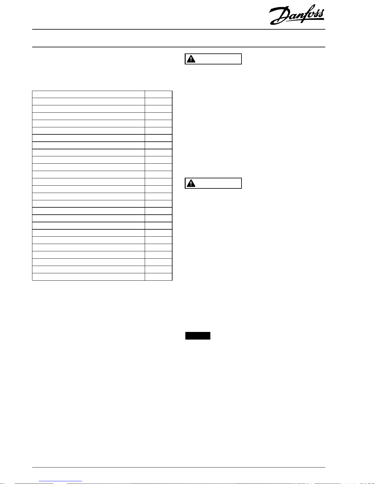
The 300 A current sensor kit contains all components required
to upgrade the current sensor assembly in D1h/D3h/D5h/D6h
drives. The kit is compatible with the power ratings shown in
Tab le 1.1 . To identify the power rating, see
chapter 1.1.1 Identifying the Power Rating.
Product group and series Voltage rating
(V)
Power rating [kW
(hp)]
VLT
®
HVAC Drive FC 102,
VLT
®
Refrigeration Drive FC 103,
VLT
®
AQUA Drive FC 202
(T4) 380–480 110–200
(150–300)
(T7) 525–690 75–315
(75–350)
VLT
®
AutomationDrive FC 302
(T5) 380–500 90–160
(125–200)
(T7) 525–690 55–250
(75–350)
Table 1.1 Applicable Power Range for 300 A Current Sensor Kit
1.1.1 Identifying the Power Rating
To nd the drive power rating, use the following steps:
1. Obtain the following information from the
nameplate, which is on the drive. Refer to
Illustration 1.1.
•
Product group and drive series
(characters 1–6)
•
Power rating (characters 7–10)
•
Voltage rating (phases and mains)
(characters 11–12)
2. Determine if the power rating is in Ta ble 1.1.
1 Product group and drive series
2Power rating
3 Voltage rating (phases and mains)
Illustration 1.1 Example Nameplate
1.1.2 Kit Ordering Number
Kit number Kit description
176F6516 300 A Current Sensor Conversion Kit for
D1h/D3h/D5h/D6h
Table 1.2 Number for 300 A Current Sensor Kit
Installation Instructions
300 A Current Sensor Kit for
D1h/D3h/D5h/D6h Drives
VLT
®
FC Series FC 102, FC 103, FC 202, FC 302
Danfoss A/S © 07/2018 All rights reserved. MI70Y202
Page 2
1.1.3 Items Supplied
Tabl e 1.3 provides a list of items included in the 300 A current
sensor kit. Refer also to Illustration 1.5.
Description Quantity
R/S/T terminal label 1
M10x30 screw 6
M10 nut 6
Mains input terminal block 1
M5x12 screw 11
EMC shield 1
U/V/W terminal label 1
Motor terminal block 1
Power terminal mounting plate (IP21/IP54) 1
Power terminal mounting plate (IP20/Chassis) 1
M8 nut 3
Mixing fan 1
Mixing fan housing 1
Insulator sleeve 1
Motor busbar (U) 1
Motor busbar (V) 1
Motor busbar (W) 1
M5x16 screw 3
M6x90 screw 3
Cylinder busbar 3
Nomex tubes 3
300 A current sensor 3
M4x10 thread-forming screw 6
Wire harness (current sensor cables) 1
M5x11 thread-forming screw 4
Table 1.3 Items Supplied in 300 A Current Sensor Kit
1.2 Safety Information
Only
qualied,
Danfoss-authorized personnel are allowed to
install the parts described in these installation instructions.
Handling of the drive and its parts must be done in
accordance with the corresponding operating guide.
WARNING
ELECTRICAL SHOCK HAZARD
VLT® FC series drives contain dangerous voltages when
connected to mains voltage. Improper installation, and
installing or servicing with power connected, can cause
death, serious injury, or equipment failure.
To avoid death, serious injury, or equipment failure:
•
Only use
qualied
electricians for the installation.
•
Disconnect the drive from all power sources before
installation or service.
•
Treat the drive as live whenever the mains voltage
is connected.
•
Follow the guidelines in these instructions and local
electrical safety codes.
WARNING
DISCHARGE TIME
The drive contains DC-link capacitors, which can remain
charged even when the drive is not powered. High voltage
can be present even when the warning LED indicator lights
are
o.
Failure to wait the
specied
time after power has
been removed before performing service or repair work can
result in death or serious injury.
•
Stop the motor.
•
Disconnect AC mains and remote DC-link power
supplies, including battery back-ups, UPS, and DClink connections to other drives.
•
Disconnect or lock PM motor.
•
Wait for the capacitors to discharge fully. The
minimum waiting time is 20 minutes.
•
Before performing any service or repair work, use
an appropriate voltage measuring device to make
sure that the capacitors are fully discharged.
NOTICE
ELECTROSTATIC DISCHARGE
Follow proper ESD precautions to prevent damage to
sensitive components.
Installation Instructions
300 A Current Sensor Kit for
D1h/D3h/D5h/D6h Drives
VLT
®
FC Series FC 102, FC 103, FC 202, FC 302
2
Danfoss A/S © 07/2018 All rights reserved. MI70Y202
Page 3

1.3 Disassembly Instructions
NOTICE
To make the disassembly/reassembly process easier, use
these general guidelines:
1. Follow the disassembly instructions for each
component.
2. Place the component together with the removed
fasteners.
3. Replace old component with the new component
provided in the kit.
4. If any fasteners are stripped or lost, replace with
similar fastener from the kit.
5. Follow the assembly instructions to replace and
secure each component.
1.3.1 General Torque Tightening Values
Use a torque wrench to ensure that correct torque is applied.
Incorrect torque can cause electrical connection problems. For
fastening hardware described in this instruction, use the values
listed in Tab le 1.4 to Tab le 1.6 except where noted in the
procedures.
Shaft
size
Tor x /h ex
drives size
Class A
Nm (in-lb)
Class B
Nm (in-lb)
M4 T20/7 mm 1.2 (10) 0.8 (7)
M5 T25/8 mm 2.3 (20) 1.2 (10)
M6 T30/10 mm 3.9 (35) 2.3 (20)
M8 T40/13 mm 9.6 (85) 3.9 (35)
M10 T50/17 mm 19.1 (169) 9.6 (85)
M12 –/18 mm or
19 mm
37.9 (335) –
Table 1.4 Torque Values Standard Thread
Shaft
size
Tor x d ri ves
size
Class A
Nm (in-lb)
Class B
Nm (in-lb)
M4.8 T25 5.7 (50) 3.1 (27)
M5 T25 1.7 (15) 1.7 (15)
Table 1.5 Torque Values for Thread Cutting into Metal
Shaft
size
Tor x d riv es
size
Class A
Nm (in-lb)
Class B
Nm (in-lb)
M4 T20 2.8 (24) 2.8 (24)
M5 T25 5.1 (45) 4.0 (35)
Table 1.6 Torque Values for Thread Forming into Plastic
Class A: Clamping metal
Class B: Clamping PCA or plastic
1.3.2 Removing AC Input Busbars
1 Nut (10 mm)
2 AC input busbars
3Nuts (13 mm)
Illustration 1.2 AC Input Busbars
To remove the AC input busbars, use the following steps. The
AC input busbars can look
dierent
when the drive includes
extra input options, such as an RFI lter or mains fuses.
Illustration 1.2 shows the AC input busbars with no input
options. Illustration 1.3 shows the AC input busbars with
optional RFI lter and mains fuses.
Installation Instructions
300 A Current Sensor Kit for
D1h/D3h/D5h/D6h Drives
VLT
®
FC Series FC 102, FC 103, FC 202, FC 302
MI70Y202 Danfoss A/S © 07/2018 All rights reserved.
3
Page 4

1. Remove the air bae by removing 4 screws (T25)
and 2 lower screws (T40). If the brake option is
present, there are no lower screws.
2. The next step diers based on the input options
present in the drive. Select the appropriate procedure
for the drive:
•
No options
•
Mains fuses only
•
RFI lter only
•
Mains fuses and RFI lter
1 AC input busbar 6 Power terminal mounting plate
2RFI lter (optional) 7 M8 nut
3 Mains fuse (optional) 8 EMC shield
4 R/S/T terminal label 9 Motor terminal
5 Mains input terminal 10 Mixing fan
Illustration 1.3 AC Input Busbars with RFI Filter and Mains Fuses
1.3.2.1 No Options
1. Remove 3 nuts (13 mm) at the top of the AC input
busbars, 1 per phase.
2. Remove 3 nuts (13 mm) at the bottom of the AC
input busbars, 1 per phase.
3. Remove 1 nut (13 mm) from the center busbar.
4. Remove the busbars from the drive.
1.3.2.2 Mains Fuses Only
1. Remove mains fuses by removing 6 nuts (13 mm), 1
at each end of the 3 fuses.
2. Remove the mains fuses from the drive.
3. Remove 3 nuts (10 mm) at the top of the AC input
busbars, 1 per phase.
4. Remove the AC input busbars.
1.3.2.3 RFI Filter Only
1. Remove 3 nuts (10 mm) at the top of the RFI lter, 1
per phase.
2. Remove 6 nuts (13 mm) at the bottom of the RFI
lter, 2 per phase.
3. Remove 4 mounting screws (T20) connecting the RFI
lter to the side channels of the drive.
4. Remove the RFI lter and unplug the RFI cable from
MK100 on the RFI lter card.
1.3.2.4 Mains Fuses and RFI Filter
1. Remove the mains fuses by removing 6 nuts (13
mm), 1 at each end of the 3 mains fuses.
2. Remove 3 nuts (10 mm) at the top of the RFI lter, 1
per phase.
3. Remove 4 screws (T20) connecting the RFI lter to
the side channels of the drive.
4. Remove the RFI
lter
and unplug the RFI cable from
MK100 on the RFI card.
1.3.3 Removing Mains Input Terminal Block
To remove the mains input terminal block, use the following
steps. Refer to Illustration 1.5.
1. Disconnect any customer input power wiring, and
remove the R/S/T terminal label.
2. Remove 2 screws (T25) at the bottom of the terminal
block.
3. Slide the mains input terminal block down to release
it from the 2 metal retaining clips on the mounting
plate. It can be necessary to remove 1 screw (T25)
from the EMC shield when removing the terminal
block.
Installation Instructions
300 A Current Sensor Kit for
D1h/D3h/D5h/D6h Drives
VLT
®
FC Series FC 102, FC 103, FC 202, FC 302
4
Danfoss A/S © 07/2018 All rights reserved. MI70Y202
Page 5

1.3.4 Removing Brake Terminal Block
(optional)
If the drive includes an optional brake, remove the brake
terminal block using the following steps.
1. Disconnect the brake wiring, if any.
2. To detach the R (+) terminal, remove 1 screw ( T25) at
the terminal block, and 1 extra screw (T40).
3. To detach the R (-) terminal, remove 1 screw (T25) at
the terminal block, and 1 extra nut (13 mm).
4. To detach the brake terminal block, remove 2 nuts
(13 mm) and lift the terminal from the drive.
1.3.5 Removing Motor Terminal Block
To remove the motor terminal block, use the following steps.
Refer to Illustration 1.5.
1. Disconnect wiring to the motor, and remove the
U/V/W terminal label.
2. Remove the EMC shield:
2a Remove 2 screws (T25).
2b Release the current sensor wiring from the
cable guides on the EMC shield.
2c Lift the EMC shield from the drive.
3. Remove the U motor busbar:
3a Remove 1 thread-forming screw (T25) from
the middle of the busbar.
3b Unfasten 1 screw (T30) at the current sensor
end of the busbar.
4. Remove the V motor busbar:
4a Remove 1 thread-forming screw (T25) from
the middle of the busbar.
4b Unfasten 1 screw (T30) at the current sensor
end of the busbar. Note that the V screw is
shorter than the U and W screws.
5. Remove the W motor busbar:
5a Remove 1 thread-forming screw (T25) from
the middle of the busbar.
5b Unfasten 1 screw (T30) at the current sensor
end of the busbar.
6. Remove 2 screws (T25) at the bottom of the motor
terminal block.
7. Remove the motor terminal block by sliding it down
to release it from the 2 metal retaining clips.
8. Remove the 3 cylinder busbars, 1 from the center of
each current sensor and discard the busbars.
1.3.6 Removing Power Terminal Mounting
Plate
To remove the power terminal mounting plate, use the
following steps. Refer to Illustration 1.4.
1. Remove the mixing fan from the slot in the power
terminal mounting plate:
1a Place the end of a screwdriver under each
of the mixing fan release tabs.
1b Lift to free the fan and housing from the
power terminal mounting plate.
1c Unplug the mixing fan in-line cable
connector.
2. Remove 4 thread-cutting screws ( T20), 2 from each
side of the power terminal mounting plate.
3. For IP21/Type 1 and IP54/Type 12 enclosures only,
loosen 3 screws ( T25) at the bottom of the drive.
4. For IP20/Chassis enclosures only, remove 3 nuts
(10 mm) from the bottom edge of the plate.
5. Unplug 3 current sensor cables, 1 from the back of
each current sensor. Unplug the 16-pin connector
from MK101 on the power card. Discard the current
sensor wire harness.
6. Remove the power terminal mounting plate with the
old current sensors attached, and discard it.
Installation Instructions
300 A Current Sensor Kit for
D1h/D3h/D5h/D6h Drives
VLT
®
FC Series FC 102, FC 103, FC 202, FC 302
MI70Y202 Danfoss A/S © 07/2018 All rights reserved.
5
Page 6

1 Current sensor 4 Mixing fan cable
2 Thread-cutting screw (T20) 5 Mixing fan
3 Power terminal mounting plate 6 Mixing fan slot
Illustration 1.4 Power Terminal Mounting Plate
Installation Instructions
300 A Current Sensor Kit for
D1h/D3h/D5h/D6h Drives
VLT
®
FC Series FC 102, FC 103, FC 202, FC 302
6
Danfoss A/S © 07/2018 All rights reserved. MI70Y202
Page 7

1.4 Assembly Guidelines
1 R/S/T terminal label 13 Insulator sleeve
2 M10x30 screw 14 U busbar
3M10 nut 15V busbar
4 Mains input terminal block 16 W busbar
5 M5x12 screw 17 M5x16 screw
6 EMC shield 18 M6x90 screw
7 U/V/W terminal label 19 Cylinder busbar
8 Motor terminal block 20 Nomex tube
9 Power terminal mounting plate (IP21/IP54) 21 Current sensor
10 M8 nut 22 M4x10 thread-forming screw
11 Mixing fan 23 Wire harness (current sensor cables)
12 Mixing fan housing – Power terminal mounting plate, not shown (IP20/Chassis)
Illustration 1.5 Exploded View of 300 A Current Sensor Kit
Installation Instructions
300 A Current Sensor Kit for
D1h/D3h/D5h/D6h Drives
VLT
®
FC Series FC 102, FC 103, FC 202, FC 302
MI70Y202 Danfoss A/S © 07/2018 All rights reserved.
7
Page 8

1.4.1 Installing Current Sensors
NOTICE
MOUNTING PLATE SELECTION
The 300 A current sensor kit includes 2 power terminal
mounting plates, select the correct plate for the enclosure.
Illustration 1.5 shows the plate for IP21/Type 1 and IP54/
Type 12 enclosures. Illustration 1.6 shows the plate for IP20/
Chassis enclosures.
To install the new current sensors on the power terminal
mounting plate, use the following steps. Refer to
Illustration 1.6.
1. Position the outer 2 current sensors at the top of the
power terminal mounting plate with the base against
the plate.
2. Invert the middle current sensor so that the base is
at the top.
3. Align the current sensors so that the cable
connectors face the back of the unit, and the arrows
on the sensors point outward.
4. Attach the 3 current sensors to the power terminal
mounting plate by fastening 6 thread-forming screws
(T20), 2 per sensor. Torque screws to 2.0 Nm
(17.7 in-lb).
5. Connect the wire harness by attaching 3 current
sensor cable connectors to the back of the current
sensors, 1 per current sensor.
6. Attach the 16-pin connector to MK101 on the power
card.
7. Route the current sensor cables through the cable
guides on the power terminal mounting plate.
1 Middle current sensor (inverted position)
2 Outer current sensor (upright position)
3Thread-forming screw (T20)
4 Power terminal mounting plate (IP20/Chassis)
Illustration 1.6 Current Sensor Mounting Position
1.4.2 Installing Power Terminal Mounting
Plate
To install the power terminal mounting plate, use the
following steps. Refer to Illustration 1.5.
1. Position the power terminal mounting plate in the
drive.
2. Fasten 4 thread-cutting screws (T20), 2 screws in
each side of the plate.
3. Attach the mixing fan cable in-line connector.
4. Insert the mixing fan into the fan housing with the
label facing the open side of the housing.
5. With the mixing fan label facing up, snap the mixing
fan assembly into the slot in the power terminal
mounting plate.
6. For IP21/Type 1 and IP54/Type 12 enclosures only,
fasten 3 screws (T25) at the bottom of the drive.
7. For IP20/Chassis enclosures only, fasten 3 M8 nuts.
Installation Instructions
300 A Current Sensor Kit for
D1h/D3h/D5h/D6h Drives
VLT
®
FC Series FC 102, FC 103, FC 202, FC 302
8
Danfoss A/S © 07/2018 All rights reserved. MI70Y202
Page 9

1.4.3 Installing Motor Terminal Block
To install the motor terminal block, use the following steps.
Refer to Illustration 1.5.
1. Position the motor terminal block by sliding it
upward under the 2 metal retaining clips.
2. Fasten 2 screws (T25) at the lower end of the motor
terminal block.
3. Place 3 Nomex tubes in the drive, 1 in the center of
each current sensor. Place the shorter tube (marked
with a red line) through the middle current sensor.
4. Place 3 cylinder busbars in the drive, 1 inside each
Nomex tube. Place the shorter busbar through the
middle Nomex tube.
5. Replace the U motor busbar:
5a Slide the insulator sleeve over the U busbar.
5b Fasten 1 screw (T30) in the current sensor
end of the busbar.
5c Fasten 1 thread-forming screw (T25) in the
middle of the busbar.
6. Replace the V motor busbar:
6a Fasten 1 screw (T30) in the current sensor
end of the busbar. Note that the V bolt is
shorter than the U/W bolts.
6b Fasten 1 thread-forming screw (T25) in the
middle of the busbar.
7. Replace the W motor busbar:
7a Fasten 1 screw (T30) in the current sensor
end of the busbar.
7b Fasten 1 thread-forming screw (T25) in the
middle of the busbar.
8. Position the EMC shield between the mains input
terminal block and motor terminal block and secure
with 2 screws (T25).
9. Reconnect wiring to motor terminals, and replace the
U/V/W terminal label.
1.4.4 Installing Brake Terminal Block (optional)
If the optional brake is present, reinstall the brake terminal
block using the following steps.
1. Position the optional brake terminal block in the
drive.
2. Secure 2 M8 nuts (T40) in the terminal block.
3. Fasten the R (-) terminal using 1 M4x8 thread-forming
screw (T20) at the terminal block, and 1 M8 nut
(T40).
4. Fasten the R (+) terminal using 1 M4x8 threadforming screw (T20) at the terminal block, and 1
screw (T40).
5. Reconnect the brake wiring.
1.4.5 Installing Mains Input Terminal Block
To install the mains input terminal block, use the following
steps. Refer to Illustration 1.5.
1. Place the mains input terminal block in position by
sliding it under the 2 metal retaining clips.
2. Secure 2 screws (T25) at the bottom of the mains
input terminal block.
3. Reconnect any customer input wiring, and replace
the R/S/T terminal label.
1.4.6 Installing AC Input Busbars
To install the AC input busbars, use the following steps. The
AC input busbars can look dierent when the drive includes
extra input options, such as an RFI
lter
or mains fuses.
Illustration 1.2 shows the drive with no input options.
Illustration 1.3
The next procedure diers based on options present in the
drive. Select the appropriate procedure for the drive:
•
No options
•
Mains fuses only
•
RFI lter only
•
Mains fuses and RFI lter
Installation Instructions
300 A Current Sensor Kit for
D1h/D3h/D5h/D6h Drives
VLT
®
FC Series FC 102, FC 103, FC 202, FC 302
MI70Y202 Danfoss A/S © 07/2018 All rights reserved.
9
Page 10

1.4.6.1 No Options
1. Position the 3 AC input busbars in the drive.
2. Fasten 1 nut (13 mm) in the center of the middle
busbar.
3. Secure 6 nuts (13 mm) at the bottom of the AC input
busbars, 1 per phase.
4. Fasten 3 nuts (13 mm) at the top of the AC input
busbars, 1 per phase.
5. Position the air
bae
in the drive, and fasten with 4
screws (T25).
1.4.6.2 Mains Fuses Only
1. Position the AC input busbars in the drive.
2. Fasten 3 nuts (13 mm) at the top of the AC input
busbars, 1 per phase.
3. Position the 3 mains fuses in the drive.
4. Fasten 6 nuts (13 mm), 1 at each end of the 3 fuses.
5. Position the air bae in the drive, and fasten with 4
screws (T25).
1.4.6.3 RFI Filter Only
1. Connect the RFI cable to MK100 on the RFI lter card.
2. Position the RFI lter in the drive.
3. Fasten 4 thread-cutting screws (T20), connecting the
RFI lter to the side channels of the drive.
4. Secure 6 nuts (13 mm) at the bottom of the RFI lter,
2 per phase.
5. Secure 3 nuts (13 mm) at the top of the RFI lter, 1
per phase.
6. Position the air
bae
in the drive, and fasten with 4
screws (T25).
1.4.6.4 Mains Fuses and RFI Filter
1. Connect the RFI cable to MK100 on the RFI card.
2. Position the RFI lter in the drive.
3. Fasten 4 thread-cutting screws ( T20), connecting the
RFI
lter
to the side channels of the drive.
4. Secure 3 nuts (13 mm) at the top of the RFI
lter,
1
per phase.
5. Secure the 3 mains fuses by fastening 6 nuts (13
mm), 1 at each end of the fuses.
6. Position the air
bae
in the drive, and fasten with 4
screws (T25).
Danfoss can accept no responsibility for possible errors in catalogues, brochures and other printed material. Danfoss reserves the right to alter its products without notice. This also applies to products already on
order provided that such alterations can be made without subsequential changes being necessary in specifications already agreed. All trademarks in this materi al are property of the respective companies. Danfoss
and the Danfoss logotype are trademarks of Danfoss A/S. All rights reserved.
Danfoss A/S
Ulsnaes 1
DK-6300 Graasten
vlt-drives.danfoss.com
*MI70Y202*
MI70Y202130R0721 07/2018
 Loading...