

Page 1
Description
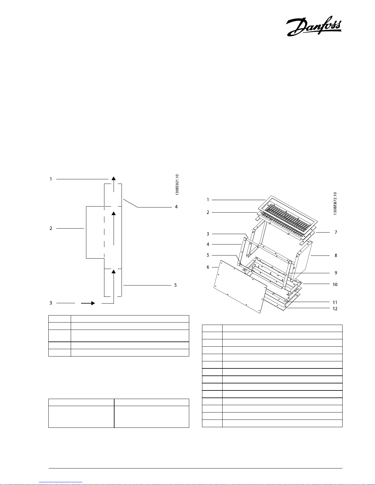
The in-bottom/out-top cooling kit is designed for the specic
VLT
®
HVAC Drive FC 102, VLT® AQUA Drive FC 202, and VLT
®
AutomationDrive FC 302 D4h-size VLT® Parallel Drive Modules
mounted in a Rittal TS8 enclosure. The kit directs air in from
the bottom of the unit and out through the top of the unit.
See Illustration 1.1.
1 Back-channel airow (exhaust)
2 Drive module
3 Back-channel airow (intake)
4 Upper duct assembly
5 Lower duct assembly
Illustration 1.1 Direction of
Airow
with the Kit Installed
Kit Part Number
Part number Kit description
176F6491 In-bottom/Out-top Cooling Kit for
the VLT
®
Parallel Drive Modules
(2-drive system)
Table 1.1 Part Number for the VLT® Parallel Drive Modules
In-bottom/Out-top Cooling Kit
Items Supplied
Enclosure mounting assembly
•
Base mounting plate, 38 mm (1.5 in.) (4)
•
Gasket, base mounting plate (4)
•
Slot gasket between drive module and mounting
backplate (2)
•
M5 nuts (20)
•
Screws, M5x16 (14)
Upper duct assembly
1 Gasket between grill and top cover panel (1)
2Grill (1)
3 Gasket, top front cover (1)
4Gasket, left front cover (1)
5 Gasket, bottom front cover (1)
6Front cover plate (1)
7 Gasket between duct enclosure and grill (1)
8 Duct enclosure (1)
9 Gasket, right front cover (1)
10 Gasket between duct enclosure and base plate (1)
11 Base plate (1)
12 Gasket between base plate and module (1)
–Nuts, M5 (26)
–Screws, M5x12 (6)
Illustration 1.2 Upper Duct Assembly for 1 Drive Module
Installation Instructions
In-bottom/Out-top Cooling Kit for VLT®
Parallel Drive Modules
VLT® Series FC 102, FC 202, and FC 302
Danfoss A/S © 04/2016 All rights reserved. MI92M102
Page 2

Lower duct assembly
1 Gasket between the top plate and the module (1)
2 Top plate between module and lower duct (1)
3Gasket, top side plate (2)
4 Gasket, upper strip on front side of duct enclosure (1)
5 Gasket between front plate and access plate (2)
6 Access plate (2)
7Front plate (1)
8 Gasket, lower strip on front side of duct enclosure (1)
9 Gasket between top plate and lower duct enclosure (1)
10 Top side plate (2)
11 Duct enclosure (1)
12 Gasket, side rail on front side of duct (2)
13 Gasket between grill and lower duct enclosure (1)
14 Bracket (3)
15 Grill (1)
16 Screw/washer assembly for bracket (3)
17 Gasket between grill and gland plate (1)
18 Base cover plate (2)
19 Gasket between base cover plate and base plate (2)
–Nuts, M5 (47) and M6 (3)
Illustration 1.3 Lower Duct Assembly for 1 Drive Module
Safety
WARNING
DISCHARGE TIME
The frequency converter contains DC-link capacitors, which
can remain charged even when the unit is o. High voltage
can be present even when the warning indicator lights are
o. Failure to wait 20 minutes after power has been
removed before performing service or repair work, could
result in death or serious injury.
•
Stop the motor.
•
Disconnect the AC mains, permanent magnet type
motors, and remote DC-link supplies, including
battery back-ups, UPS, and DC-link connections to
other frequency converters.
•
Wait 20 minutes for the capacitors to discharge fully,
before performing any service or repair work.
•
Measure the voltage level to verify full discharge.
Installation
NOTICE
If both a bus bar kit and a back-channel cooling kit are
being installed in the cabinet, install the back-channel
cooling kit rst.
NOTICE
APPROVALS AND CERTIFICATIONS
This VLT® Parallel Drive Modules back-channel cooling kit is
UL 508C compliant. These installation instructions describe
how to install the back-channel cooling kit which, if
followed, meet specic agency approvals and certications.
Seek agency approvals or
certications
apart from Danfoss if
designing and building other congurations.
NOTICE
APPLYING GASKETS
This kit contains gaskets to ensure a proper seal between
metal parts. Before adhering a gasket to a part, check that
the part matches the gasket and that no holes are covered.
Remove paper backing and place the sticky side on the part.
Installation Instructions
In-bottom/Out-top Cooling Kit for VLT®
Parallel Drive Modules
VLT® Series FC 102, FC 202, and FC 302
2
Danfoss A/S © 04/2016 All rights reserved. MI92M102
Page 3

Assembling the Lower Duct Enclosure
1. Position the duct enclosure (11) as shown in Illustration 1.4.
2. Install the top plate assembly.
2a Place the U-shaped gasket (9) along the top edge of the duct enclosure.
2b Apply the gasket (1) to the top side of the top plate (2). Leave the paper backing on the adhesive until the duct
is ready to install on the drive module.
2c Install the top plate, with the studs facing down, onto the top of the duct enclosure. Secure with 4 M5 nuts and
torque to 5.1 N · m (45 in-lb).
2d Install the top side plate gaskets (3) to the underside of the top plate (2).
2e Install both top side plates (10) over the top side plate gaskets. Secure each top side plate with 5 M5 nuts and
torque to 5.1 N · m (45 in-lb).
2f Apply the upper strip gasket (4) to the top plate
ange
along the front of the duct enclosure.
3. Install the grill assembly to the base of the duct enclosure.
3a Apply the gasket (13) to the base of the duct enclosure.
3b Apply the gasket (17) to the base of the grill plate.
3c Install the grill (15) with the ange facing upward onto the duct enclosure base.
3d Apply the lower strip gasket (8) to the grill plate ange.
3e Fasten the grill to the duct enclosure using the 3 brackets (14). Each bracket is placed over a stud on the grill
and lines up with 2 studs in the duct enclosure.
3f Secure each bracket to the duct enclosure with 2 M5 nuts. Torque to 5.1 N · m (45 in-lb).
3g Secure the grill to each bracket using 1 M6 nut. Torque to 6.0 N · m (53 in-lb).
4. Assemble the backplate.
4a Apply 1 gasket (5) onto the studs along the edge of each opening on the front plate.
4b Install the access plates (6) over the gaskets and openings in the front plate.
4c Secure each access plate with 8 M5 nuts and torque to 5.1 N · m (45 in-lb).
5. Apply gaskets (12) to each side rail on the duct enclosure.
6. Install the front plate (7) and secure with 11 M5 nuts. Torque to 5.1 N · m (45 in-lb).
Installation Instructions
In-bottom/Out-top Cooling Kit for VLT®
Parallel Drive Modules
VLT® Series FC 102, FC 202, and FC 302
MI92M102 Danfoss A/S © 04/2016 All rights reserved.
3
Page 4

Illustration 1.4 Assembling the Lower Duct Enclosure
1 Gasket between the top plate and the module 11 Duct enclosure
2 Top plate between module and lower duct 12 Gasket, side rail on back side of duct
3 Gasket, top side plate 13 Gasket between grill and duct enclosure
4 Gasket, upper strip on back side of duct 14 Bracket
5 Gasket between front plate and access plate 15 Grill
6 Access plate 16 Screw/washer assembly for bracket
7 Front plate 17 Gasket between grill and gland plate
8 Gasket, lower strip on back side of duct 18 Base cover plate
9 U-shaped gasket 19 Gasket between base cover plate and base plate
10 Top side plate – –
Installation Instructions
In-bottom/Out-top Cooling Kit for VLT®
Parallel Drive Modules
VLT® Series FC 102, FC 202, and FC 302
4
Danfoss A/S © 04/2016 All rights reserved. MI92M102
Page 5

Assembling the Upper Duct Assembly
1. On the top side of the enclosure, install the gasket (7) and then the grill (2). Secure the grill with 8 M5 nuts and torque to
5.1 N · m (45 in-lb).
2. Install the gasket (1) on top of the grill. Leave the paper backing on the adhesive until ready to install on the drive
module.
3. Turn the duct enclosure over so the base of the enclosure is facing up. Install the gasket (10) on the base of the
enclosure.
4. Place the base plate (11) on the gasket (10). Secure with 8 M5 nuts and torque to 5.1 N · m (45 in-lb).
5. On the front side of the enclosure (8), install the 4 gaskets (3, 4, 5, 9).
6. Place the front cover plate (6) on top of the gaskets. Secure the front cover plate to the enclosure using 8 M5 nuts.
Tor que to 5.1 N · m (45 in- lb).
7. Install the gasket (12) on top of the base plate.
1 Gasket between grill and the top panel cover 7 Gasket between duct enclosure and grill
2Grill 8 Duct enclosure
3 Gasket, top front cover 9 Gasket, right front cover
4 Gasket, left front cover 10 Gasket between duct enclosure and base plate
5 Gasket, bottom front cover 11 Base plate
6 Front cover plate 12 Gasket between base plate and module
Illustration 1.5 Assembling the Upper Duct Assembly
Installation Instructions
In-bottom/Out-top Cooling Kit for VLT®
Parallel Drive Modules
VLT® Series FC 102, FC 202, and FC 302
MI92M102 Danfoss A/S © 04/2016 All rights reserved.
5
Page 6

Mounting the Drive Modules
1. Install the mounting backplate to the cabinet rails, making sure that the pem studs/nuts are facing toward the back of the
enclosure.
2. Install gaskets to the back side of the drive module. Refer to Illustration 1.6.
2a Install gasket (6) over the vent opening.
2b Align the slot gasket (7) with the lower mounting holes in the drive module and install the gasket onto the drive
module.
3. Install the base mounting plates. Refer to Illustration 1.7.
3a Assemble the 2 base mounting plates by attaching the gasket (4) onto the base mounting plate (5).
3b Insert an M10 screw (6) through the mounting plate/gasket assembly and loosely fasten into the mounting
backplate. Perform this step again for the other mounting plate/gasket assembly. Make sure that the screws are
secure since the base of the drive module rests on these screws.
4. Slightly lean the top of the drive module forward and set the cutouts in the base of the module onto the lower 2 M10
screws in the mounting backplate.
5. Slowly push the top of the drive module back against the mounting backplate until the top 2 holes on the module line
up with the 2 mounting holes in the mounting backplate. Secure the top of the drive module using 2 M10 screws and
torque to 19 N · m (170 in-lb).
6. Torque the M10 screws securing the base of the module to 19 N · m (170 in-lb).
7. Remove the DC fuses from the top of the drive module.
8. Install the upper duct assembly. Refer to Illustration 1.6.
8a Remove the paper backing from the top gasket.
8b Place the upper duct assembly on top of the drive module, making up sure the mounting holes line.
8c Secure the duct assembly to the drive module with 6 M5x12 screws. Torque to 5.1 N · m (45 in-lb).
9. Reinstall the DC fuses on top of the drive module.
10. Install the next drive module to the mounting backplate.
Installation Instructions
In-bottom/Out-top Cooling Kit for VLT®
Parallel Drive Modules
VLT® Series FC 102, FC 202, and FC 302
6
Danfoss A/S © 04/2016 All rights reserved. MI92M102
Page 7

1 M5x12 screws 5 Lower mounting point for drive module (M10 pem nut)
2 Upper duct assembly 6 Gasket between back exhaust and mounting backplate
3 Upper mounting point for drive module (M10 pem nut) 7 Slot gasket
4 Mounting backplate – –
Illustration 1.6 Installing the Drive Modules onto the Mounting Backplate
Installation Instructions
In-bottom/Out-top Cooling Kit for VLT®
Parallel Drive Modules
VLT® Series FC 102, FC 202, and FC 302
MI92M102 Danfoss A/S © 04/2016 All rights reserved.
7
Page 8

Installing the Lower Duct Assembly
Refer to Illustration 1.7 for the following steps.
1. Remove the paper backing from the top plate gasket.
2. Place the lower duct assembly up against the drive
module base, making sure that the mounting holes
align.
3. Secure the lower duct assembly to the base of the
drive module using 7 M5x16 screws. Torque to 5.1 N ·
m (45 in-lb).
4. Install the lower duct assembly on the next drive
module.
1 Drive module
2Slot gasket
3 Cutout in drive module base that rests on the M10 screw
4 Gasket, base mounting plate, 38 mm (1.5 in)
5 Base mounting plate, 38 mm (1.5 in)
6M10 screw
7 M5x16 screw
8Lower duct assembly
Illustration 1.7 Installing the Lower Duct Assembly
Installing the Top Panel Cover
1. Cut out the 2 exhaust vent openings in the top panel
cover. The openings must match to the exhaust vent
openings on the upper duct assembly. Refer to
Illustration 1.8.
2. Secure the top panel cover to the frame.
Illustration 1.8 Vent Dimensions for the Top Panel Cover
Installing the Base Cover Plate and
Back Panel Cover
1. Cut out 2 vent openings in the base plate. Refer to
the shaded area dimensions in Illustration 1.9.
2. Create openings for the cables. Refer to the area
marked with diagonal lines. Seal the cable entry once
the cables are connected.
3. Drill 24 screw holes around the vent openings and
install 24 M5 pem nuts. Refer to Illustration 1.10.
4. Secure the base plate to the enclosure, pem nuts
facing the oor.
5. Install a gasket (19) around each of the vent
openings on the base cover plate. When installed,
this gasket faces the base plate. Refer to
Illustration 1.4.
6. For each lower duct assembly, slip the base cover
plate (18) between the duct assembly and the base
plate. Align the opening on the base cover plate with
the gasket (17) on the lower duct assembly.
7. Secure each lower duct assembly to the base cover
plate.
7a Install 1 screw/washer assembly (16) per
bracket (14). Loosely fasten the screw/
washer assembly.
7b Loosen, but do not remove, the M6 nut on
the bracket.
7c Torque the screw/washer assembly to 5.1 N
· m (45 in-lb).
7d Torque the M6 nut to 3.0 N · m (27 in-lb).
8. Secure each base cover plate to the base plate using
12 M5 screws. Torque to 5.1 N · m (45 in-lb).
9. Secure the back panel cover to the frame.
Installation Instructions
In-bottom/Out-top Cooling Kit for VLT®
Parallel Drive Modules
VLT® Series FC 102, FC 202, and FC 302
8
Danfoss A/S © 04/2016 All rights reserved. MI92M102
Page 9

Illustration 1.9 Vent Opening Dimensions for the Base Plate
1 M5 pem nut (24 total on base plate)
Illustration 1.10 M5 Pem Nut Dimensions on the Base Plate
Installation Instructions
In-bottom/Out-top Cooling Kit for VLT®
Parallel Drive Modules
VLT® Series FC 102, FC 202, and FC 302
MI92M102 Danfoss A/S © 04/2016 All rights reserved.
9
Page 10

Danfoss can accept no responsibility for possible errors in catalogues, brochures and other printed material. Danfoss reserves the right to alter its products without notice. This also applies to products already on
order provided that such alterations can be made without subsequential changes being necessary in specifications already agreed. All trademarks in this material are property of the respective companies. Danfoss
and the Danfoss logotype are trademarks of Danfoss A/S. All rights reserved.
Danfoss A/S
Ulsnaes 1
DK-6300 Graasten
vlt-drives.danfoss.com
*MI92M102*
MI92M102130R0693 04/2016
 Loading...