

Page 1

Installation Instructions
Inrush Card Kit for D1h–D8h Drives
®
VLT
FC Series FC 102, FC 103, FC 202, FC 302
1.1 Description
The inrush card kit includes all parts required to install the
inrush card in D1h–D8h drives.
1.1.1 Kit Ordering Numbers
Number Kit description
176F3159 Inrush card NO 110–315 kW 400 V (T5)
176F3417 Inrush card NO 75–400 kW 690 V (T7)
176F3517 Inrush card rugged NO 110–315 kW 400 V (T5)
176F3518 Inrush card rugged NO 75–400 kW 690 V (T7)
Table 1.1 Ordering Numbers for Inrush Card Kits
1.1.2 Items Supplied
The following items are included with the inrush card kits for
D1h–D8h drives.
Item Quantity
Inrush card 1
Stando (for D1h/D3h/D5h/D6h drives only) 3
Installation instructions 1
Table 1.2 Items Supplied with Inrush Card Kit
1.2 Safety Information
Only qualied, Danfoss-authorized personnel are allowed to
install the parts described in these installation instructions.
Disassembly and reassembly of the drive must be done in
accordance with the corresponding service guide.
WARNING
ELECTRICAL SHOCK HAZARD
VLT® FC series drives contain dangerous voltages when
connected to mains voltage. Improper installation, and
installing or servicing with power connected, can cause
death, serious injury, or equipment failure.
To avoid death, serious injury, or equipment failure:
Only use
•
Disconnect the drive from all power sources before
•
installation or service.
Treat the drive as live whenever the mains voltage
•
is connected.
Follow the guidelines in these instructions and local
•
electrical safety codes.
qualied
electricians for the installation.
WARNING
DISCHARGE TIME
The drive contains DC-link capacitors, which can remain
charged even when the drive is not powered. High voltage
can be present even when the warning LED indicator lights
are o. Failure to wait the specied time after power has
been removed before performing service or repair work can
result in death or serious injury.
Stop the motor.
•
Disconnect AC mains and remote DC-link power
•
supplies, including battery back-ups, UPS, and DClink connections to other drives.
Disconnect or lock PM motor.
•
Wait for the capacitors to discharge fully. The
•
minimum waiting time is 20 minutes.
Before performing any service or repair work, use
•
an appropriate voltage measuring device to make
sure that the capacitors are fully discharged.
NOTICE
ELECTROSTATIC DISCHARGE
Follow proper ESD precautions to prevent damage to
sensitive components.
Danfoss A/S © 05/2018 All rights reserved. MI39A102
Page 2

Installation Instructions
Inrush Card Kit for D1h–D8h Drives
®
FC Series FC 102, FC 103, FC 202, FC 302
VLT
1.3 Installation Instructions for D1h/D3h/D5h/D6h Drives
Illustration 1.1 shows an exploded view of the main components of the D3h drive. The components of the D1h/D5h/D6h drives are
similar.
1 Local control panel (LCP) and LCP cradle 10 Balance/high frequency card
2 Control card mounting plate 11 Top fan (IP20 only)
3 Power card mounting plate 12 Inrush card
4 Gatedrive card 13 DC inductor
5 RFI lter (optional) 14 SCR/diode modules
6 Gatedrive card support bracket 15 Brake IGBT module (optional)
7 Mains input terminal block 16 IGBT modules
8 Motor terminal block 17 Capacitor bank
9 Power terminal mounting plate 18 Heat sink fan
Illustration 1.1 Exploded View of D3h Drive
2
Danfoss A/S © 05/2018 All rights reserved. MI39A102
Page 3

Installation Instructions
Inrush Card Kit for D1h–D8h Drives
®
FC Series FC 102, FC 103, FC 202, FC 302
VLT
1.3.1 Accessing the Inrush Card in D1h/D3h/Dh5/D6h Drives
To access the inrush card, remove the following components from the drive. Refer to Illustration 1.1 and Illustration 1.2. See the
service guide for detailed instructions for each component.
1. Remove the control card mounting plate.
2. Remove the power card mounting plate.
3. Remove the AC input busbars and any input options present, such as RFI lter or mains fuses.
4. Remove the mains input terminal block and EMC shield.
5. Remove the brake terminals, if present.
6. Remove the motor terminal block.
7. Remove the power terminal mounting plate.
8. Remove the DC bus rails.
1Screw (T30) 7 Nut (10 mm)
2 Inrush card 8 Screw (T30)
3DC(+) busbar 9 Screw (T30)
4 Inrush support bracket 10 DC(+) busbar
5 Stando (11 mm) 11 DC(-) busbar DC coil to capacitor bank
6 DC coil to capacitor bank DC(-) busbar – –
Illustration 1.2 Inrush Card and DC Bus Rails
MI39A102 Danfoss A/S © 05/2018 All rights reserved.
3
Page 4

Installation Instructions
Inrush Card Kit for D1h–D8h Drives
®
FC Series FC 102, FC 103, FC 202, FC 302
VLT
1.3.2 Removing the Inrush Card in D1h/D3h/D5h/D6h Drives
To remove the inrush card, use the following steps. Refer to Illustration 1.2.
1. Unplug the cables from the following connectors on the inrush card:
MK1800
•
MK1802
•
2. Remove 5 screws (T20) from the inrush card.
3. Remove the inrush card from the drive, and discard it.
1.3.3 Replacing the
Standos
in D1h/D3h/D5h/D6h Drives
NOTICE
STANDOFF REPLACEMENT
Only D1h/D3h/D5h/D6h drives require replacement of the standos. For all other drives, use the installed standos.
After removing the inrush card, compare the
old
standos,
Illustration 1.2 and Illustration 1.3.
1. Remove 3 standos (11 mm), 1 from each SCR input busbar.
2. Fasten 3 new standos (11 mm), 1 in each SCR busbar. Torque to 2.3 Nm (20 in-lb).
replace them with the new
standos
standos
installed in the drive to the
included in the kit. To replace the
standos
in Illustration 1.3. If the drive contains
standos,
use the following steps. Refer to
1 Old stando
2 New stando (included in kit)
Illustration 1.3
4
Stando
Replacement
Danfoss A/S © 05/2018 All rights reserved. MI39A102
Page 5

Installation Instructions
Inrush Card Kit for D1h–D8h Drives
®
FC Series FC 102, FC 103, FC 202, FC 302
VLT
1.3.4 Installing the Inrush Card in D1h/D3h/Dh5/D6h Drives
To install the new inrush card, use the following steps. Refer to Illustration 1.2.
1. Place the new inrush card in the drive.
2. Fasten 5 screws (T20) in the inrush card.
3. Plug the cables to the following connectors on the inrush card:
MK1800
•
MK1802
•
1.3.5 Reassembling D1h/D3h/D5h/D6h Drives
After installing the new inrush card and standos, replace the following components in the drive. Refer to Illustration 1.1. See the
service guide for detailed instructions for each step.
1. Replace the DC bus rails.
2. Replace the power terminal mounting plate.
3. Replace the motor terminal block.
4. Replace the optional brake terminals, if present.
5. Replace the mains input terminal block and EMC shield.
6. Replace the AC input busbars and any power options, such as RFI
7. Replace the power card mounting plate.
8. Replace the control card mounting plate.
or mains fuses.
lter
MI39A102 Danfoss A/S © 05/2018 All rights reserved.
5
Page 6

Installation Instructions
Inrush Card Kit for D1h–D8h Drives
®
FC Series FC 102, FC 103, FC 202, FC 302
VLT
1.4 Installation Instructions for D2h/D4h/D7h/D8h Drives
Illustration 1.4 shows the control card mounting plate and power card mounting plate in a D-sized drive. The location of these
components is similar in D2h/D4h/D7h/D8h drives.
1 LCP (Local control panel) 4 Screw (T20)
2 LCP cradle 5 Power card
3 Control card mounting plate 6 Power card mounting plate
Illustration 1.4 Control Card Mounting Plate and Power Card Mounting Plate
1.4.1 Accessing the Inrush Card in D2h/D4h/Dh7/D8h Drives
To access the inrush card, remove the following components from the drive. Refer to Illustration 1.4. See the service guide for
detailed instructions for each component.
1. Remove the control card mounting plate.
2. Remove the power card mounting plate.
6
Danfoss A/S © 05/2018 All rights reserved. MI39A102
Page 7
Installation Instructions
Inrush Card Kit for D1h–D8h Drives
®
FC Series FC 102, FC 103, FC 202, FC 302
VLT
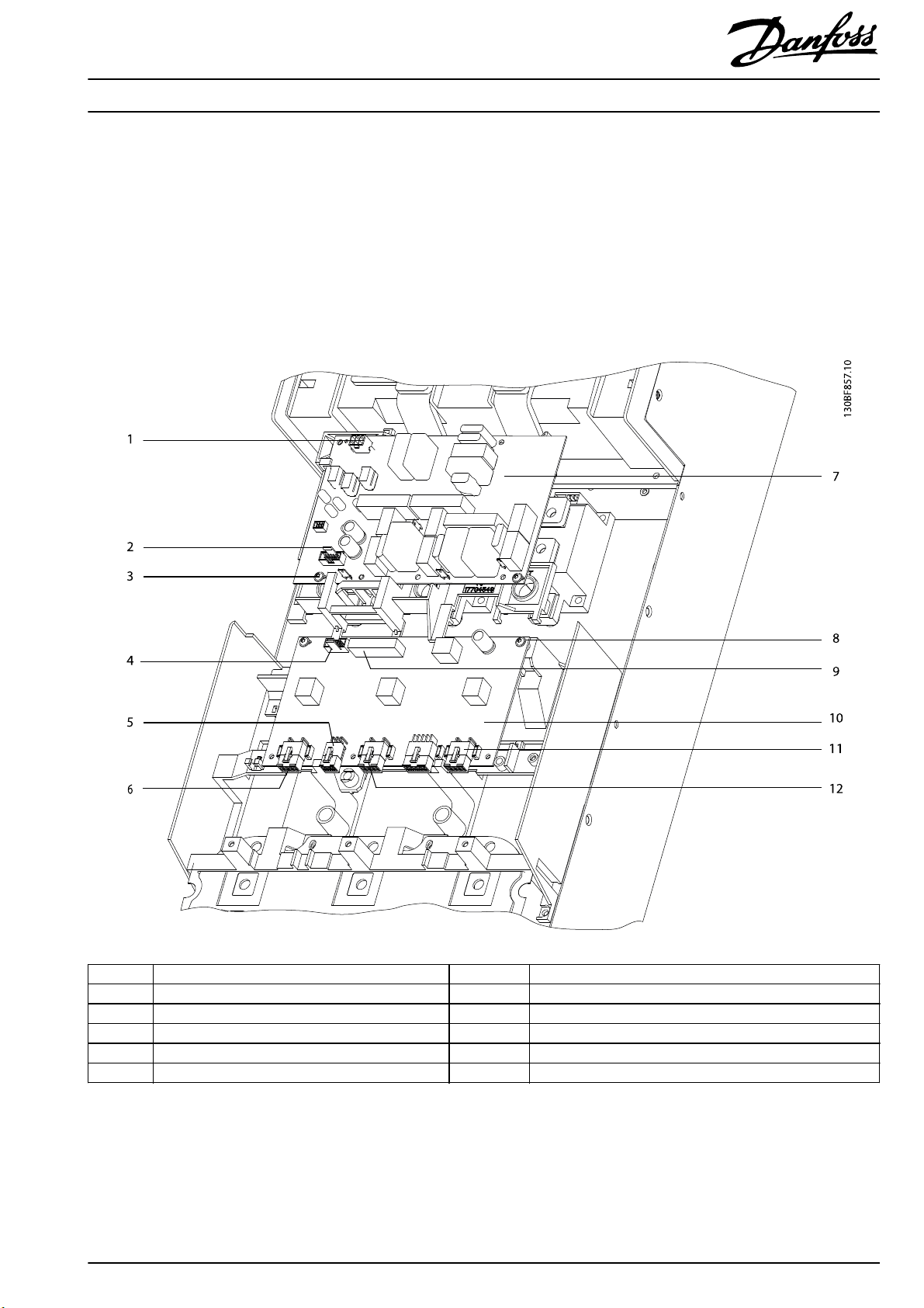
1.4.2 Removing the Inrush Card in D2h/D4h/D7h/D8h Drives
To remove the inrush card, use the following steps. Refer to Illustration 1.5.
1. Unplug the cable from the inrush card connector MK1802.
2. Remove 2 thread-forming screws (T20).
3. Remove 5 screws (T20) from the inrush card.
4. Remove the inrush card from the drive, and discard it.
1MK1802 7 Inrush card
2MK1800 8 Screw (T20)
3 Screw ( T20) 9 MK101
4MK102 10 Gatedrive card
5 MK100 11 MK701
6 MK501 12 MK601
Illustration 1.5 Inrush Card and Gatedrive Card
MI39A102 Danfoss A/S © 05/2018 All rights reserved.
7
Page 8

1.4.3 Installing the Inrush Card in D2h/D4h/D7h/D8h Drives
To install the new inrush card, use the following steps. Refer to Illustration 1.5.
1. Position the inrush card in the drive.
2. Secure 5 screws (T20) in the inrush card.
3. Secure 2 thread-forming screws (T20).
4. Connect the cable to the inrush card connector MK1802.
1.4.4 Reassembling D2h/D4h/D7h/D8h Drives
After installing the new inrush card, replace the following components in the drive. Refer to Illustration 1.4. See the service guide for
detailed instructions for each component.
1. Replace the power card mounting plate.
2. Replace the control card mounting plate.
Danfoss can accept no responsibility for possible errors in catalogues, brochures and other printed material. Danfoss reserves the right to alter its products without notice. This also applies to products already on
order provided that such alterations can be made without subsequential changes being necessary in specifications already agreed. All trademarks in this mate rial are property of the respective companies. Danfoss
and the Danfoss logotype are trademarks of Danfoss A/S. All rights reserved.
Danfoss A/S
Ulsnaes 1
DK-6300 Graasten
vlt-drives.danfoss.com
MI39A102130R0846 05/2018
*MI39A102*
 Loading...