

Dan Dugan Sound Design E-2 User Manual

Dan Dugan Sound Design
Model E-2 Automatic Mixing Controller
User Guide
Release Date: August 2013
Version: 1.0
Author: Rob Wenig

Important Safety Instructions and Warnings
The Model E-2’s circuitry is made in the USA and meets applicable national safety standards.
Standards Compliance
The third-party power supply provided with this product has been certified to comply with UL.
Safety Instructions
1. Read these instructions.
2. Keep these instructions.
3. Heed all warnings.
4. Follow all instructions.
5. Do not use this apparatus near water.
6. WARNING! To reduce the risk of fire or electric shock, do not expose this apparatus
to rain or moisture.
7. Clean only with dry cloth.
8. Do not block any ventilation openings. Install in accordance with the manufacturer’s
instructions.
9. Do not install near any heat sources such as radiators, heat registers, stoves, or other
apparatus (including amplifiers) that produce heat.
10. Do not defeat the safety purpose of the polarized or grounding-type plug. A polarized
plug has two blades with one wider than the other. A grounding type plug has two
blades and a third grounding prong. The wide blade or the third prong are provided for
your safety. If the provided plug does not fit into your outlet, consult an electrician for
replacement of the obsolete outlet.
11. Protect the power cord from being walked on or pinched particularly at plugs, conve-
nience receptacles, and the point where they exit from the apparatus.
12. Only use attachments/accessories specified by the manufacturer.
13. Unplug this apparatus during lightning storms or when unused for long periods of time.
14. WARNING! Refer all servicing to qualified service personnel. Servicing is required
when the apparatus has been damaged in any way, such as power-supply cord or plug is
damaged, liquid has been spilled or objects have fallen into the apparatus, the apparatus
has been exposed to rain or moisture, does not operate normally, or has been dropped.
15. WARNING! To reduce the risk of electric shock, DO NOT REMOVE COVER. No
user serviceable parts inside.

Warranty Statement
Warranty: One year parts and labor
Dan Dugan Sound Design warrants that Model E-2 hardware will be free from defects in
components and workmanship for a period of 12 months from the date of invoice. During the
warranty period, Dan Dugan Sound Design will cover the cost of all parts and labor to remedy
the defect, or replace products which prove to be defective. Dan Dugan Sound Design is
not obliged to honor this warranty if the hardware has failed to be maintained and operated
as specified by Dan Dugan Sound Design, in the accompanying documentation, or other
than in accordance with industry standards. Defects caused by unauthorized modifications,
misuse, negligence, act of God or accident are not covered by this warranty. Software is
provided as a convenience, but due to the wide variety of computer systems, cannot be
guaranteed to work. This Limited Warranty is exclusive and no other warranty is expressed
or implied. Dan Dugan Sound Design does not warrant that Dan Dugan Sound Design software, or any third-party software, is error free. Third party branded or manufactured
goods are supplied by Dan Dugan Sound Design with care but without responsibility
and subject only to third party suppliers’ warranties. In all other respects Dan Dugan
Sound Design is not liable for consequential damages.


Dugan Model E-2 User Guide
Table of Contents
Chapter 1: Introduction ............................................................................................. 9
Dugan Speech System Theory............................................................ 10
Dugan Music System and Gain Limiting Theory.......................... 11
Model E-2 Modes..................................................................................... 13
Eight-channel........................................................................................ 13
Twelve-channel..................................................................................... 13
Sixteen-channel ................................................................................... 13
Chapter 2: Quickstart ............................................................................................... 15
Chapter 3: Installation and Configuration.................................................. 17
Rack Mounting .......................................................................................... 17
Power Supply ............................................................................................. 18
System Reset ............................................................................................ 18
Rear Panel I/O Connections................................................................ 19
Analog .................................................................................................. 20
Digital .................................................................................................. 21
Music System Threshold Inputs ........................................................ 21
Linking .......................................................................................................... 22
Patching the Model E-2 as an Insert to your Console .............. 22
Unprocessed Outputs ............................................................................ 22
Mix Matrix Outputs .................................................................................. 23
Connecting the Model CP-2 Control Panel..................................... 23
Connecting to a Computer ................................................................... 24
5

Dugan Model E-2 User Guide
Chapter 4: Stand-alone Operation.................................................................... 31
Settings........................................................................................................ 31
If You Must Use a Pre-fader Insert ................................................... 33
Muting Channels.................................................................................. 33
Pre-listening to Muted Channels ....................................................... 34
Chapter 5: Dugan Control Panel Software................................................. 35
The Top Pane............................................................................................. 37
Adding Units Manually ........................................................................ 37
Selecting Units to Display .................................................................. 38
Setting Controls........................................................................................ 38
Naming Units and Channels................................................................ 39
Channel Pane ............................................................................................ 39
Level Indicator...................................................................................... 40
Bypass .................................................................................................. 40
Channel Modes.................................................................................... 41
Preset .................................................................................................. 42
Channel Groups ................................................................................... 42
Override................................................................................................. 43
Meters .................................................................................................. 43
Weight Controls ................................................................................... 44
Master Pane............................................................................................... 46
Selecting the Number of Channels ................................................... 47
Reset .................................................................................................. 48
Meters .................................................................................................. 48
System.................................................................................................. 48
Mix Bus Matrix ..................................................................................... 49
Group Master Controls ....................................................................... 50
6

Dugan Model E-2 User Guide
Dugan Music System and Gain Limiting......................................... 51
Dugan Music System .......................................................................... 51
Gain Limiting ........................................................................................ 54
Chapter 6: Updates..................................................................................................... 57
Appendix A: Power-up Commands ...................................................................... 59
System Reset ............................................................................................ 59
Network Reset........................................................................................... 59
DHCP On ...................................................................................................... 59
Number of Channels Mode .................................................................. 60
Appendix B: Connector Pinouts ........................................................................... 61
Appendix C: Specifications ...................................................................................... 65
7

Dugan Model E-2 User Guide
8

Dugan Model E-2 User Guide
Chapter 1: Introduction
The Model E-2 Automatic Mixing Controller helps professional audio mixers handle
multiple live mics without having to continually ride their individual faders. This
signal processor patches into the input insert points of an audio mixing console. It
detects which mics are being used and makes fast, transparent cross-fades, freeing the
mixer to focus on balance and sound quality instead of being chained to the faders.
The Model E-2 tracks unscripted dialogue, eliminating cueing mistakes and late fadeups, while avoiding the choppy and distracting effects common to noise gates.
The Model E-2 supports a broad spectrum of live mixing applications:
• Conference reinforcement, video trucks
• Houses of worship
• TV news and sports panels, reality and game shows
• Wireless mics for theater
• Boardrooms and civic meeting rooms
• Teleconferencing and distance learning
The Model E-2 dramatically improves live mixing with multiple mics by:
• eliminating late upcuts;
• reducing PA feedback and studio noise;
• reducing comb filtering from adjacent mics.
The Model E-2 can:
• be physically controlled from its own front panel, or the Model CP-2 Control Panel
(sold separately);
• be remote controlled from the Dugan Control Panel for Java (included) and Dugan
Control Panel for iPad (sold separately);
• conveniently connect multiple devices via four network ports;
• link with other Dugan automatic mixing controllers to create a larger system;
• partition channels into one to three groups that can span linked units;
• create separate linked systems that do not interact (i.e., for separate studios).
9
Dugan Model E-2 User Guide
Dugan Speech System Theory
The Dugan Model E-2 Automatic Mixing Controller uses the Dugan Speech System™, a patented and trademarked automatic mixing function. The Dugan Speech
System distributes the gain of one open microphone over the entire system, maintaining a natural one-mic ambience. It is essential to distinguish this behavior from the annoying fluctuation of levels and uneven ambience in a conventional gating system.
The system automatically manages any number of live mics in unpredictable dialogue situations. When one person speaks, that mic’s gain fades up instantly, and the
others down. When the speaker pauses, all mics fade to medium gains that sum to
equal one mic at full gain. The result sounds like passing one mic around among the
speakers. When several people talk at once, the gain is shared.
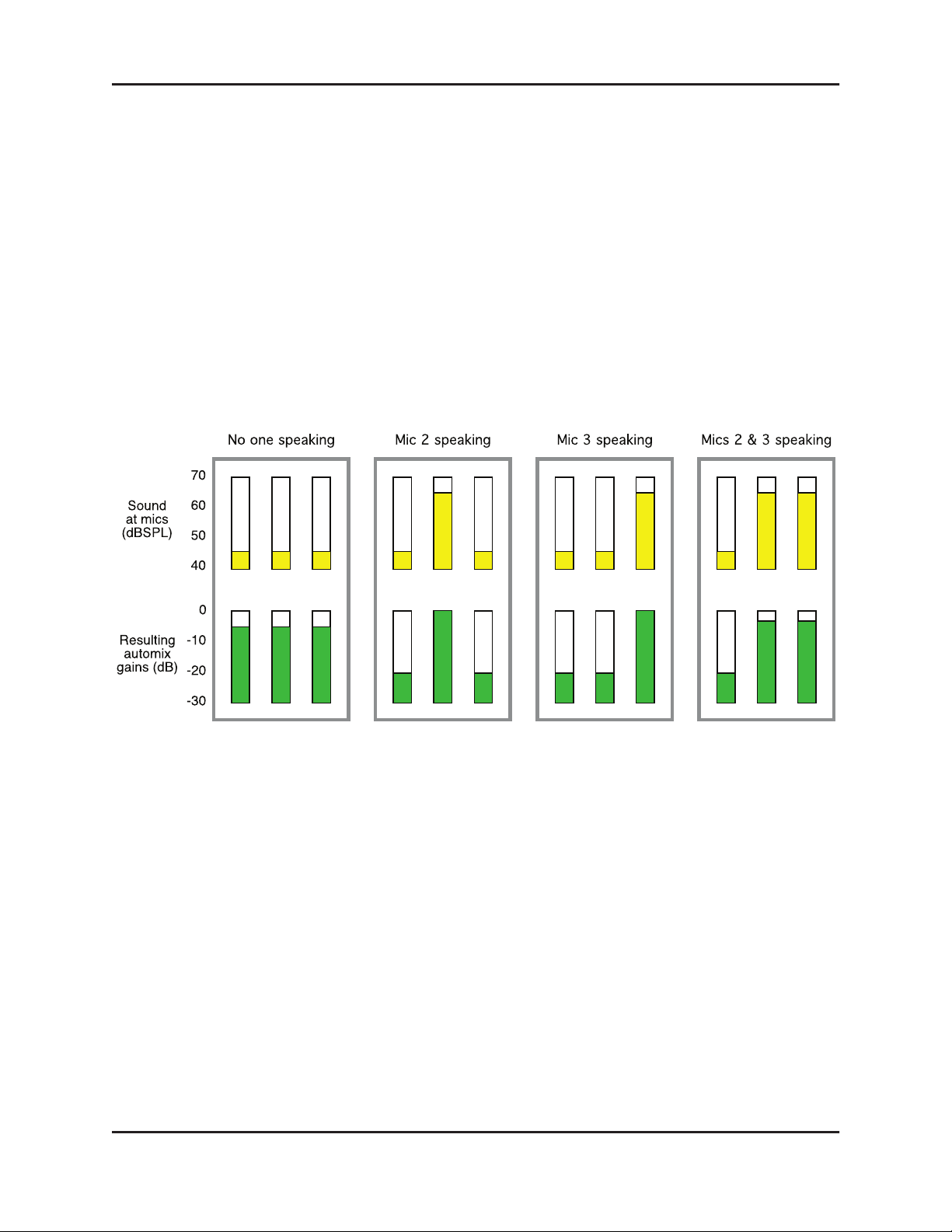
Figure 1-1 Four snapshots of a three-mic system
Figure 1-1 shows the Speech System in action with a three-mic system.
• The first frame shows no one speaking; the sound levels at all mics are low. The
system fades all channels to medium gains that sum to the equivalent of one mic
at full gain.
• The second frame shows one person speaking. The system automatically fades his/
her gain to full, while the other two inputs are turned down.
• The third frame shows a different person speaking. The system automatically
fades his/her gain to full, while the other two inputs are turned down.
• The fourth frame shows two people speaking simultaneously. The system automatically shares the gain between them, while the other input is turned down.
10
Dugan Model E-2 User Guide Introduction
Dugan Music System and Gain Limiting Theory
These functions require the physical Model CP-2 or Dugan Control Panels for Java or
iPad. See Dugan Music System and Gain Limiting on page 51 for more information on
setting up the Music System.
Dugan Music System
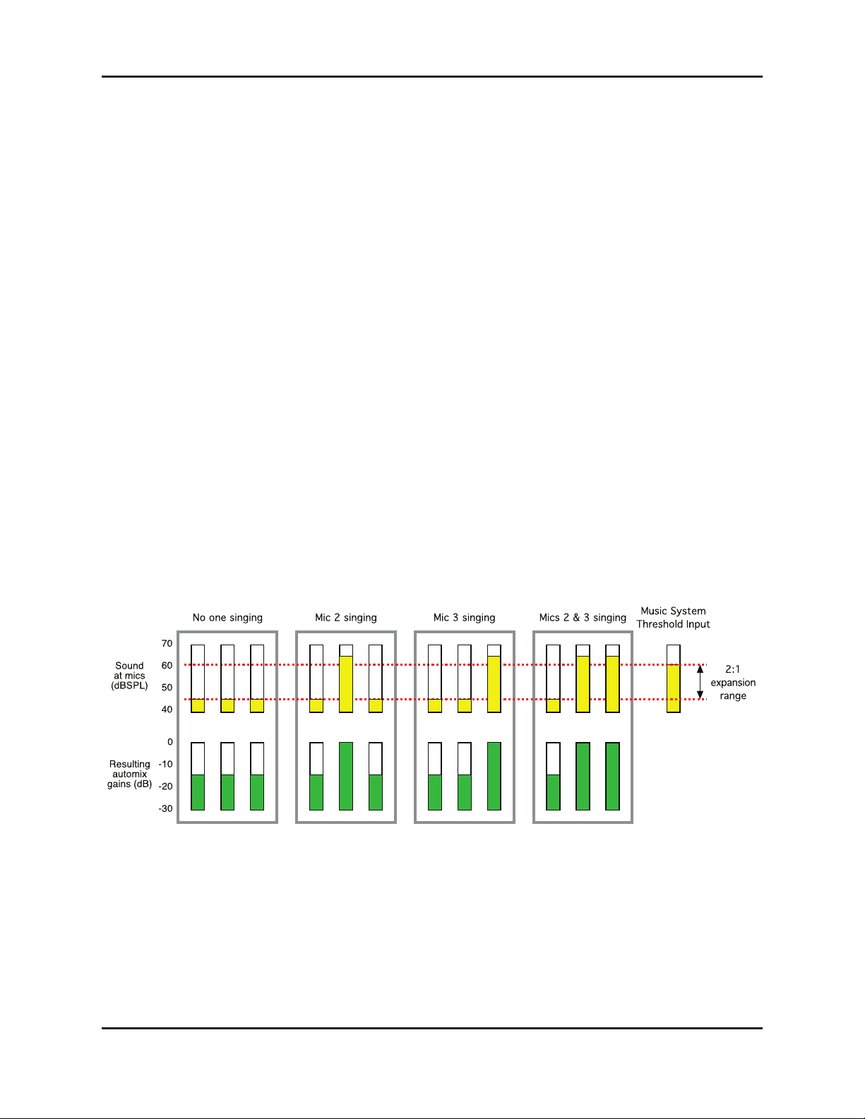
The Dugan Music System is a soft-gating or ducking system with its threshold set by
an audio side-chain, typically from a mic measuring the ambient sound level. Each
channel has a 2:1 expansion ratio below the floating threshold. There are three Music
System Threshold inputs on the
group.
The Music System can also be used to duck an audience mix when the people on
stage talk, attenuating the sound of the PA in the room. Use an aux send of the stage
vocal mix to supply the threshold signal instead of a mic.
AUDIO I/O 9–12 connector (channels 9–11), one for each
The following example (
background vocalists.
• Frame 1 shows no one singing. The system keeps all channels at a low gain.
• Frame 2 shows one person singing. The system automatically fades his/her gain to
full, while the other two inputs stay low.
Figure 1-2) shows how the Music System works with three
Figure 1-2 Function of the Dugan Music System
• Frame 3 shows a different person singing. The system automatically fades his/her gain
to full, while the previous singer’s mic and the other input stay low.
• Frame 4 shows two people singing together. The system automatically gives their
channels full gain, while the other input stays low.
11
Dugan Model E-2 User Guide
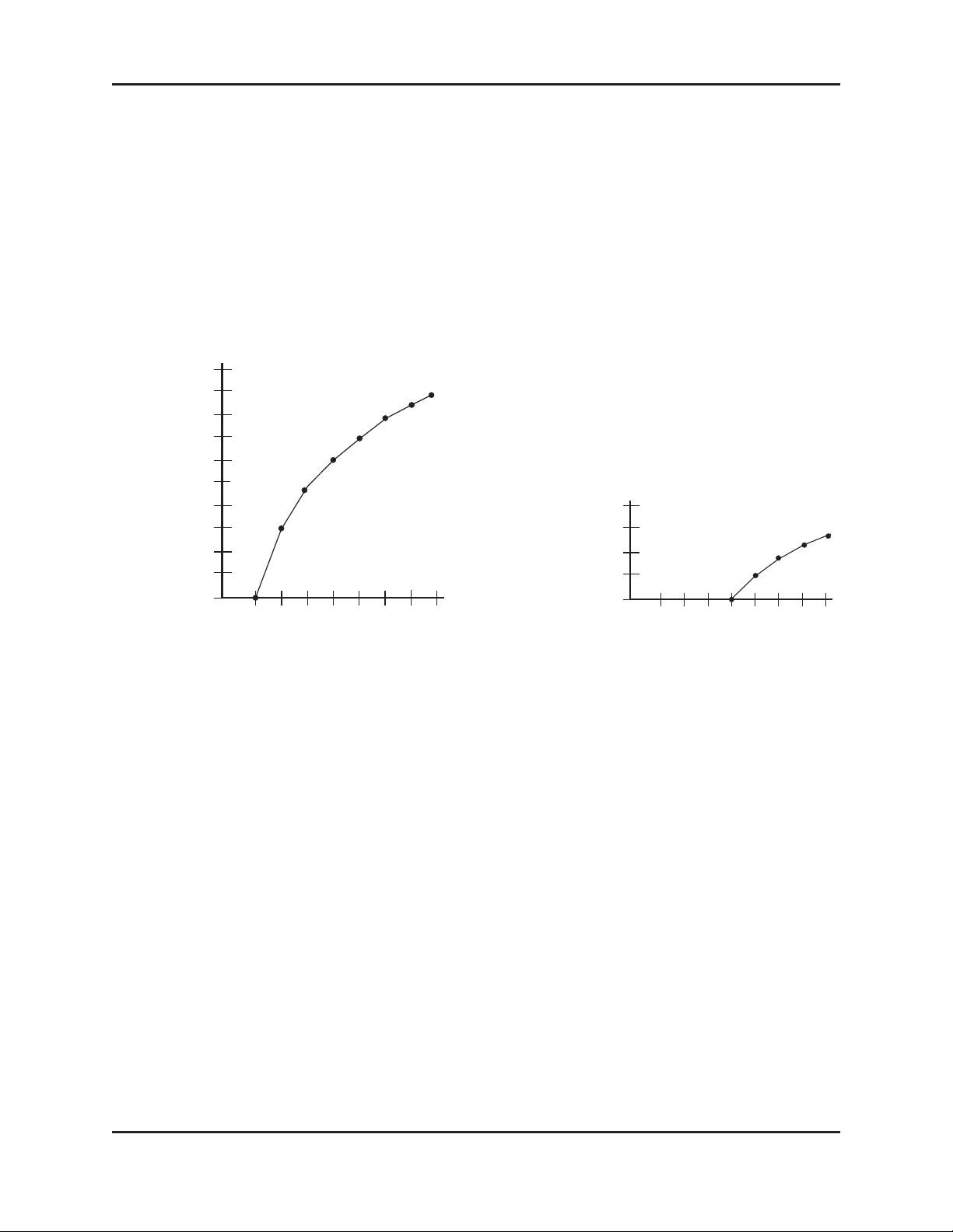
Gain Limiting
Gain Limiting reduces master gain as new mics enter the system, thus avoiding feedback and noise. This is commonly called NOM (Number of Open Mics) gain adjustment. Unlike NOM functions on other systems, Dugan Gain Limiting doesn’t just
count how many mics are on. It sums the gains of all active channels (including partially attenuated channels), compares them to a gain threshold, and reduces the gain
appropriately.
Conventional automatic mixing implementations always assume an NOM of 1.
10
8
Gain
Reduction
(dB)
6
4
2
0
0
2
Number of Open Mikes
4
(NOM)
6
8
Gain
Reduction
(dB)
4
2
0
0
2
Number of Open Mikes
4
(NOM)
6
Figure 1-3 NOM and gain reduction: NOM =1 (left); NOM = 4 (right)
The Dugan’s unique implementation allows you to set the number of mics at full
gain before gain limiting occurs.
For example, if there is enough gain before feedback to tolerate four open mics, the
gain limit can be set to 4. Gain reduction begins when the fifth mic turns on.
8
12

Dugan Model E-2 User Guide Introduction
Model E-2 Modes
The Model E-2 is an eight-channel audio processor offering three Dugan algorithms.
However, it can operate in twelve- or sixteen-channel modes with reduced features.
See Chapter 3: Installation and Configuration to learn how to choose a mode with the
#ch button during installation.
Eight-channel
• The Dugan Speech System™ provides automatic mixing for eight live mics.
• The Dugan Music System™ offers automatic downward expansion to help reduce
feedback and bleed in live music performances (i.e., opera, background vocals).
Thresholds are adjusted automatically by monitoring ambient noise levels.
• Dugan Gain Limiting™ monitors the number-of-open-mics (NOM) and adjusts
the master gain to prevent feedback or ambient noise build-up. Dugan Gain
Limiting should be used with the Dugan Music System to reduce feedback and
noise. It can perform the same functions when mics are switched on and off
manually.
• Linking creates one large automatic mixing system with multiple Dugan units.
• An internal mix bus matrix routes processed or unprocessed inputs to four mix
bus outputs.
• Unprocessed outputs are provided: analog inputs are mirrored at the digital output, and vice versa. This provides convenient pre-processing signals for multitrack
recording.
Twelve-channel
• The Dugan Speech System™ provides automatic mixing for twelve live mics.
• Linking creates one large automatic mixing system with multiple Dugan units.
Sixteen-channel
• The Dugan Speech System™ provides automatic mixing for sixteen live mics.
This is a digital connection that uses both the AUD and LINK ADAT optical connectors.
13

Dugan Model E-2 User Guide
14
Dugan Model E-2 User Guide
Chapter 2: Quickstart
This section provides step-by-step instructions to help you get started quickly using
the Dugan Speech System to mix up to eight channels. Twelve- and sixteen-channel
I/O is available using the Dugan Control Panel software. See Chapter 5: Dugan Control
Panel Software to learn about these options.
1. Connect the provided power supply to the Model E-2.
2. Hold the channel 1 bypass button down and power up the unit. Keep holding the
bypass button down for three seconds until the unit finishes booting.
This System Reset command sets all parameters to factory default settings and
clears label text.
We recommend executing a System Reset before starting a new installation. This
is just like zeroing a console before a show.
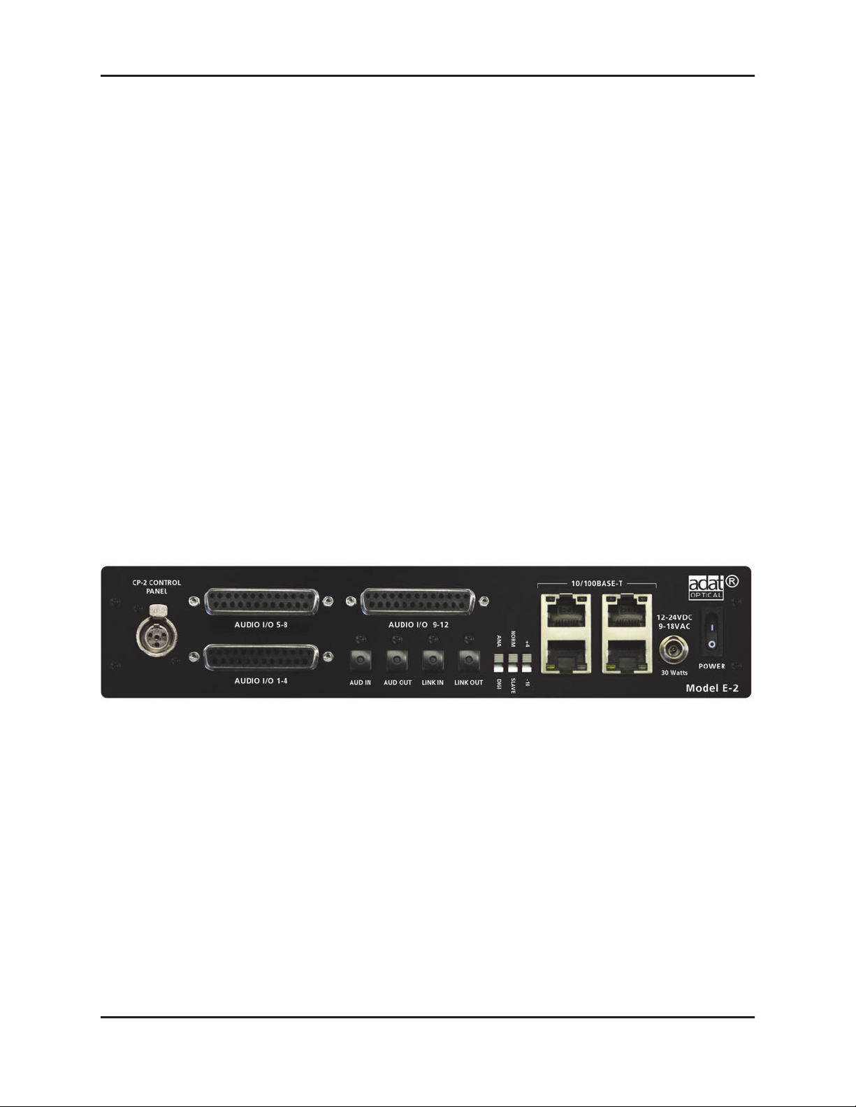
3. Set the NORM-SLAVE switch on the rear panel to NORM (up) for unlinked operation.
The Model E-2 can be interfaced using balanced analog or digital optical connectors:
4. Analog: Move the ANA-DIGI switch on the rear panel to the ANA (up) position.
The DB25 connectors carry balanced analog signals. Each connector provides four
inputs and four outputs.
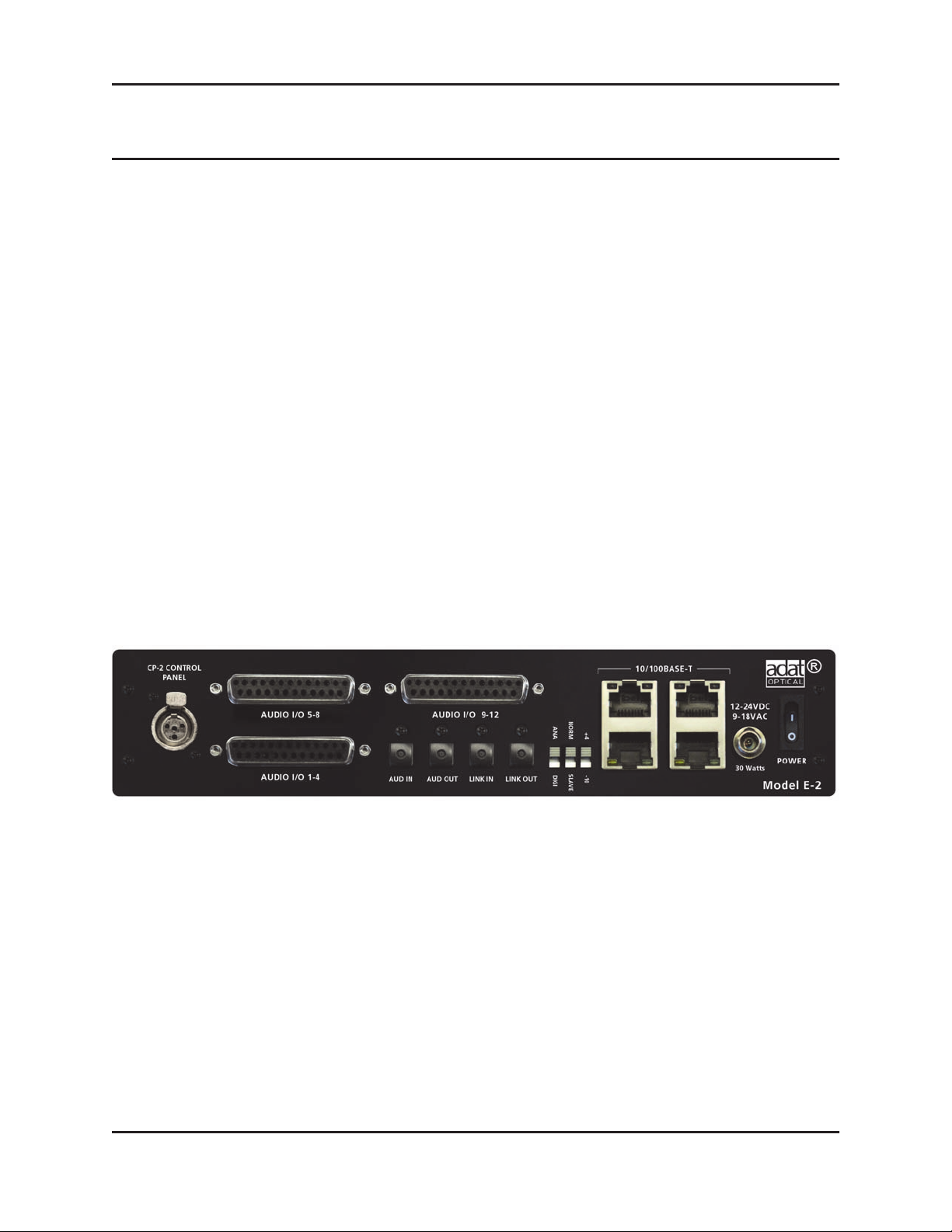
Figure 2-1 Model E-2 rear panel
Digital: Move the ANA-DIGI switch on the rear panel to the DIGI (down) position,
connect the console ADAT output to AUD IN, and connect AUD OUT to the console’s
ADAT input.
5. Whenever possible, route each Model E-2 channel as a post-fader, pre-compressor
insert to each mic channel.
15
Dugan Model E-2 User Guide
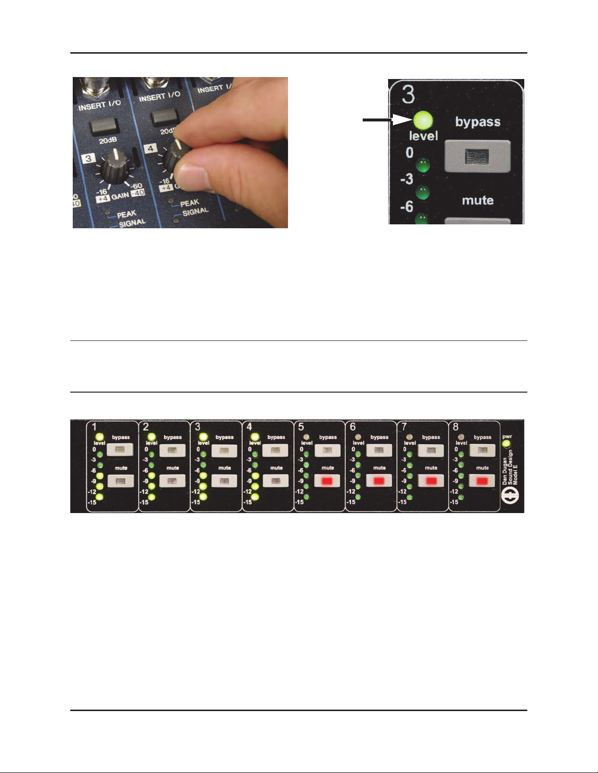
6. With the room quiet, raise your console preamp gains until the Model E-2’s green
level LEDs stay illuminated.
The level LED illuminates green when the input level is within the acceptable
range for automatic mixing and flashes red to indicate clipping. There should be
enough gain ahead of the Model E-2 to maintain the green LED at all times.
stays lit
green
Figure 2-2 Setting console preamp gain
NOTE: When the green level light extinguishes, the channel is in a downward expansion mode
to avoid feedback. This condition should be avoided because the smooth ambience that
characterizes Dugan automatic mic mixing is lost.
Figure 2-3 During ambience with 4 mics, auto mix gain displays should hover around -6 dB
7. Adjust your console’s preamp gains so all LED meters float at about the same gain
when no one is talking. This procedure assures smooth automatic mixing.
16

Dugan Model E-2 User Guide Installation and Configuration
Chapter 3: Installation and Configuration
We recommend placing the Model E-2 in a convenient place in the engineer’s line
of sight.
Figure 3-1 Model E-2 placed conveniently
Rack Mounting
All E-Series Dugan controllers are a half-rack wide, so one or two can be mounted in
a single rack space. Each unit ships with one long and one short rack ear and one
joining plate.
The rack ears for older E-Series Dugans differ slightly from the current design, but the
joining plates are the same. All E-Series Dugans can be mounted side-by-side using
the appropriate rack ear for each unit.
To mount one unit: Attach one long and one short rack ear, then mount in the rack.
To mount two units side-by-side:
1. For the left unit, remove the four screws from the right side of the top and bottom
lids.
2. Attach the top and bottom joining plates to the left unit.
3. For the right unit, remove the four screws from the left side of the top and bottom
lids.
4. Attach the top and bottom joining plates to the right unit.
5. Attach the appropriate rack ears to the left and right units.
6. Mount the pair in the rack.
17

Dugan Model E-2 User Guide
Power Supply
Units shipped to the USA include a 12 V, 1.5 A, 120 VAC power supply. Contact the
factory if you require a different power supply. In an emergency, the Model E-2 can
accept power supplies within the following ranges:
• 12–24 VDC, either polarity, 1.5 A
• 9–18 VAC, 1.5 A
System Reset
Hold down the channel 1 bypass button and power up the unit. Keep holding the by-
pass
button down for about three seconds until the unit finishes booting.
This System Reset command restores all parameters to factory default settings and
clears label text. This is just like zeroing a console before a show. We recommend executing a System Reset before starting a new installation.
The Model E-2 can execute four other power-up commands (see Appendix A: Power-
up Commands).
NOTE: If for any reason you cannot connect to a computer, power-up commands can establish
essential settings.
18
Dugan Model E-2 User Guide Installation and Configuration
Rear Panel I/O Connections
The Model E-2 provides the following rear panel I/O connectors:
• AUDIO I/O 1–4
• AUDIO I/O 5–8
• AUDIO I/O 9–12
Each DB25 connector carries four input and four output analog channels. All analog audio connections are balanced.
To connect with XLR connectors, use readily available adapter squids. Although
the Model E-2 uses these connectors for analog I/O, they are wired according to
the TASCAM digital standard.
• AUD IN, AUD OUT
These ADAT connectors carry eight audio I/O channels.
• LINK IN, LINK OUT
These ADAT connectors carry proprietary linking data. They can also be re-assigned
as eight additional audio channels.
• CP-2 CONTROL PANEL
This carries RS422 data to and from the Model CP-2 Control Panel.
Figure 3-2 Model E-2 rear panel I/O connectors
19

Dugan Model E-2 User Guide
Analog
Move the ANA-DIGI switch to ANA (up position).
If you do not need the Dugan Music System, twelve channels of automixing are available using all three DB25 connectors.
The content of the
AUDIO I/O 9–12 DB25 connector depends on the state of the #ch
switch. This can be set in the Dugan Control Panel (see Chapter 4: Dugan Control Panel) or with a power-up command (see Appendix A: Power-up Commands).
+4/-10
This sets the input sensitivity, internal headroom, and output level between professional (+4) and consumer (-10) audio line levels.
8-Ch
• Eight automix channels on the AUDIO I/O 1–4 and AUDIO I/O 5–8 DB25 connectors
• Three Music System threshold inputs on the AUDIO I/O 9–12 (channels 9–11)
Channel 12 is an auxiliary input sent to the mix bus matrix.
• Four mix bus outputs on AUDIO I/O 9–12 (channels 9–12)
• Linking available on LINK IN, LINK OUT
• Unprocessed outputs are available on AUD OUT
NOTE: Since relays route the audio input signals for channels 1–12 directly to their respective
outputs when the unit is off, you can leave it patched when not in use.
12-Ch
• Twelve automix channels on all three DB25 connectors
• Linking available on LINK IN, LINK OUT
• Music System and mix buses not available
20

Dugan Model E-2 User Guide Installation and Configuration
Digital
Move the ANA-DIGI switch to the DIGI (down) position. This switches the I/O to the
ADAT connectors.
The state of the #ch switch determines the I/O count and linking capability. This can
be set in the Dugan Control Panel (see Chapter 4: Dugan Control Panel) or with a power-up command (see Appendix A: Power-up Commands).
8-Ch
• Channels 1–8 on AUD IN/AUD OUT
• Linking and Music System available
The Music System threshold inputs are still input as analog signals on AUDIO I/O 9–
12 (channels 9–11).
• Mix bus outputs available on AUDIO I/O 9–12 (channels 9–12)
• Unprocessed outputs are available on AUDIO I/O 1–4 and AUDIO I/O 5–8
16-Ch
• Channels 1–8 on AUD IN/AUD OUT
• Channels 9–16 on LINK IN/LINK OUT
• Dugan Music System, input splits, mix bus outputs, and linking not supported
Music System Threshold Inputs
A Music System threshold signal can be provided as a reference for each group. When
the levels of channels in the group exceed the level of the Music System threshold
signal, the channels come up to full gain.
The sensing mics are typically input to the same console as the program mics, but are
routed to direct outputs or sends, not mix buses.
AUDIO I/O 9–12 DB25 connector can receive three Music System threshold inputs,
The
one for each group (a, b, c on channels 9, 10, 11).
21
 Loading...