

Dan Dugan Sound Design E-1A User Manual

Dan Dugan Sound Design
Models E-1 and E-1A
Automatic Mixing Controllers
User Guide
Release Date: August 2013
Version: 3.2
Author: Rob Wenig

Important Safety Instructions and Warnings
The Model E-1A’s circuitry is made in the USA and meets applicable national safety standards.
Standards Compliance
The third-party power supply provided with this product has been certified to comply
with UL.
Safety Instructions
1. Read these instructions.
2. Keep these instructions.
3. Heed all warnings.
4. Follow all instructions.
5. Do not use this apparatus near water.
6. WARNING! To reduce the risk of fire or electric shock, do not expose this apparatus to rain or moisture.
7. Clean only with dry cloth.
8. Do not block any ventilation openings. Install in accordance with the manufacturer’s instructions.
9. Do not install near any heat sources such as radiators, heat registers, stoves, or
other apparatus (including amplifiers) that produce heat.
10. Do not defeat the safety purpose of the polarized or grounding-type plug. A polarized plug has two blades with one wider than the other. A grounding type plug
has two blades and a third grounding prong. The wide blade or the third prong
are provided for your safety. If the provided plug does not fit into your outlet,
consult an electrician for replacement of the obsolete outlet.
11. Protect the power cord from being walked on or pinched particularly at plugs,
convenience receptacles, and the point where they exit from the apparatus.
12. Only use attachments/accessories specified by the manufacturer.
13. Unplug this apparatus during lightning storms or when unused for long periods
of time.
14. WARNING! Refer all servicing to qualified service personnel. Servicing is re-
quired when the apparatus has been damaged in any way, such as power-supply
cord or plug is damaged, liquid has been spilled or objects have fallen into the apparatus, the apparatus has been exposed to rain or moisture, does not operate
normally, or has been dropped.
15. WARNING! To reduce the risk of electric shock, DO NOT REMOVE COVER. No
user serviceable parts inside.

Warranty Statement
Warranty: One year parts and labor
Dan Dugan Sound Design warrants that Model E-1A hardware will be free from defects in components and workmanship for a period of 12 months from the date of invoice. During the warranty period, Dan Dugan Sound Design will cover the cost of all
parts and labor to remedy the defect, or replace products which prove to be defective.
Dan Dugan Sound Design is not obliged to honor this warranty if the hardware has
failed to be maintained and operated as specified by Dan Dugan Sound Design, in the
accompanying documentation, or other than in accordance with industry standards.
Defects caused by unauthorized modifications, misuse, negligence, act of God or accident are not covered by this warranty. Software is provided as a convenience, but
due to the wide variety of computer systems, cannot be guaranteed to work. This
Limited Warranty is exclusive and no other warranty is expressed or implied. Dan Dugan Sound Design does not warrant that Dan Dugan Sound Design software, or any
third-party software, is error free. Third party branded or manufactured goods are
supplied by Dan Dugan Sound Design with care but without responsibility and
subject only to third party suppliers’ warranties. In all other respects Dan Dugan
Sound Design is not liable for consequential damages.


Dugan Models E-1 and E-1A User Guide
Table of Contents
Chapter 1: Introduction ............................................................................................. 7
Theory of Operation................................................................................... 7
Remote Control and Software............................................................... 9
Model E-1 vs. E-1A .....................................................................................9
Chapter 2: Quickstart ............................................................................................... 11
Connections................................................................................................ 11
Analog I/O ............................................................................................ 11
Digital I/O ............................................................................................. 12
Power-up Reset Command................................................................... 12
Linking Multiple Dugans........................................................................ 13
Operation..................................................................................................... 14
Chapter 3: Installation and Configuration.................................................. 15
Installation .................................................................................................. 15
Rack Mounting ..................................................................................... 15
Power Supply........................................................................................ 16
Audio Wiring ......................................................................................... 16
Signal Levels ........................................................................................ 19
Linking Multiple Dugans ..................................................................... 19
Configuration.............................................................................................. 20
Power-up Commands .......................................................................... 20
Connecting to a Computer.................................................................. 22
5

Dugan Models E-1 and E-1A User Guide
Chapter 4: Dugan Control Panel ....................................................................... 29
The Top Pane............................................................................................. 30
Setting Controls and Naming Units/Channels .............................. 31
Setting Controls ................................................................................... 31
Naming Units and Channels ............................................................... 31
Channel Pane ............................................................................................ 32
Level Indicator...................................................................................... 32
Bypass................................................................................................... 33
Channel Modes .................................................................................... 33
Preset.................................................................................................... 34
Channel Groups.................................................................................... 35
Override................................................................................................. 35
Meters ................................................................................................... 36
Weight Controls ................................................................................... 36
Master Pane............................................................................................... 39
Indicators .............................................................................................. 39
Controls................................................................................................. 40
Chapter 5: Standalone Hardware Operation............................................. 43
Settings ........................................................................................................ 43
Muting Channels on a Pre-fader Insert ............................................ 45
Pre-listening to Muted Channels Using a Post-fader Insert ............ 46
Chapter 6: Updates..................................................................................................... 47
Appendix A: Specifications .................................................................................... 49
Appendix B: Connector Pinouts .......................................................................... 51
6

Dugan Models E-1 and E-1A User Guide
Chapter 1: Introduction
The Model E-1A Automatic Mixing Controller helps professional audio engineers
handle multiple live mics without continually riding individual faders. This multichannel audio signal processor patches into the channel insert points of a mixing
console. The Model E-1 detects which mics are being used, and makes fast, transparent crossfades. This eliminates late upcuts, reduces system noise and feedback, and
lets the engineer focus on balance and sound quality. The Model E-1A has both analog and digital I/O connectors.
The Model E-1A enhances a diverse group of live applications that require multiple
mics:
• Conference reinforcement, video trucks
• Houses of worship
• Film and television dialogue, reality shows
• Theater
• Boardrooms, civic meetings, community TV
• Teleconferencing and distance learning
Several features expand the Model E-1A’s capabilities:
• 16-channel mode (option for digital interface only)
• Dugan Control Panel software offers additional controls
• Linking allows up to eight Dugan units to work as one large automatic mixer
Theory of Operation
The Dugan Model E-1A Automatic Mixing Controller uses the Dugan Speech System™,
a patented and trademarked automatic mixing function. This results in a natural
one-mic ambience with minimal noise or feedback. The Dugan Speech System does
not limit, compress, or control levels. It performs just one critical function: cuing multiple live mics in situations with unpredictable dialogue. It is essential to distinguish
this behavior from the distracting fluctuation of levels and uneven ambience produced by a conventional noise gate.
7

Dugan Models E-1 and E-1A User Guide
When one person talks at a time, the Dugan Speech System rapidly fades that mic’s
gain up and the others down. When the speaker pauses, that mic fades down and the
others up, so the gain of all mics sums to equal that of one mic at full gain. When
the next person talks, the system fades that mic’s gain up and the others down. The
result sounds like passing one mic among several speakers.
When multiple people talk at once, the gain is shared among active mics. All mics
sound normal when used but there is no change in ambience, noise buildup, or feedback.
While people are talking, use the console’s faders to set appropriate relative levels for
each mic channel. You can leave the faders up when the mics are not used because
the Dugan Speech System cues the mics up when needed.
Figure 1-1 shows four snapshots of the Dugan Speech System in action with three
mics.
No one speaking Mic 2 speaking Mic 3 speaking Mics 2 and 3 speaking
70
Sound
at mics (dB)
Resulting
automix
gains (dB)
60
50
40
0
-10
-20
-30
1234
Figure 1-1 Dugan Speech System
Frame 1: No one is speaking and the sound levels at all mics are low. The system fades
all channels to a medium gain that sums to one mic at full gain.
Frame 2: One person speaks alone. The system automatically fades their gain to full,
and turns the other two inputs down.
Frame 3: The first person finishes speaking and a second person begins. The system
automatically fades the new speaker’s input gain to full, and turns the other two down.
Frame 4: Two people speak simultaneously. The system automatically shares the
gain between them, and turns the other input down.
8

Dugan Models E-1 and E-1A User Guide Introduction
Remote Control and Software
Two Java applets are provided on a thumb drive or CD, or can be downloaded from
our website:
• The Dugan Control Panel offers expanded operational capabilities (see Chapter 4:
Dugan Control Panel).
• The Dugan Utility helps you connect to a network and update the firmware (see
Chapter 6: Updates).
The Model E-1A can be controlled three ways:
• Front panel
• Dugan Control Panel
• ASCII commands via Ethernet (contact Dan for information)
Subscribe to the duganusers Yahoo group to be notified when updates are available.
Model E-1 vs. E-1A
For serial numbers 417 and above, the Model E-1 is now called Model E-1A. Model E-1s
can use the latest software as described in this manual. However, only the Model E-1A
provides the following additional features:
• Eight and sixteen channel modes
• Groups a, b, and c
• Input and output level meters
• Locking power connector
9

Dugan Models E-1 and E-1A User Guide
10
Dugan Models E-1 and E-1A User Guide
Chapter 2: Quickstart
This section provides step-by-step instructions to help you get started quickly. It includes information to connect and install the Model E-1A, make initial settings, and
link units.
Connections
1. Connect the provided power supply to the Model E-1A.
2. Set the NORM-SLAVE switch on the rear panel to NORM (up) for normal (not linked)
operation.
The Model E-1A can be interfaced with an analog or digital console using analog
or digital connections.
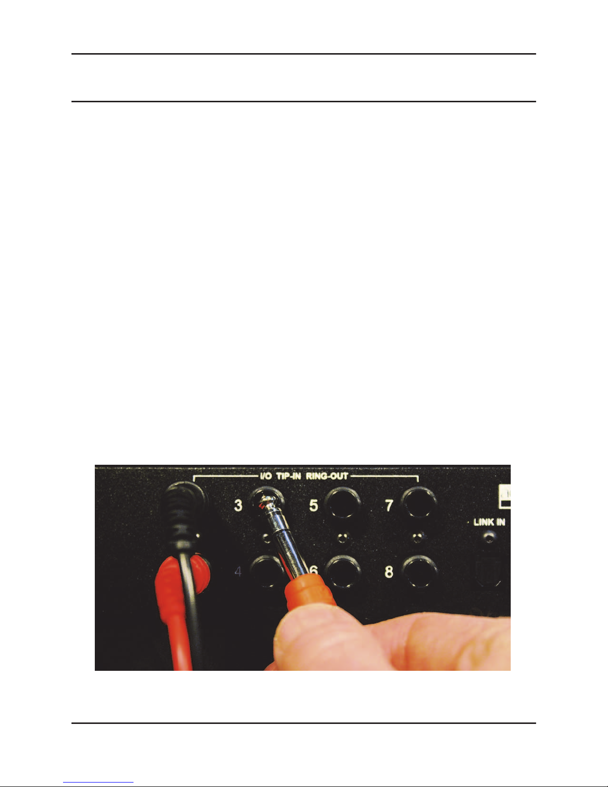
Analog I/O
1. Move the I/O switch on the rear panel to the ANALOG (up) position.
The Model E-1A is a line-level device normally patched into the insert jacks (send
and return) for each mic input channel on the board.
2. Check the insert jack wiring on your console.
If they are 1/4-in TRS jacks (wired tip = send, ring = return), use TRS-TRS insert cables to connect the Model E-1A. Other configurations require special cables. The
Model E-1A is wired as follows: tip = input, ring = output.
Figure 2-1 Analog connection
11
Dugan Models E-1 and E-1A User Guide
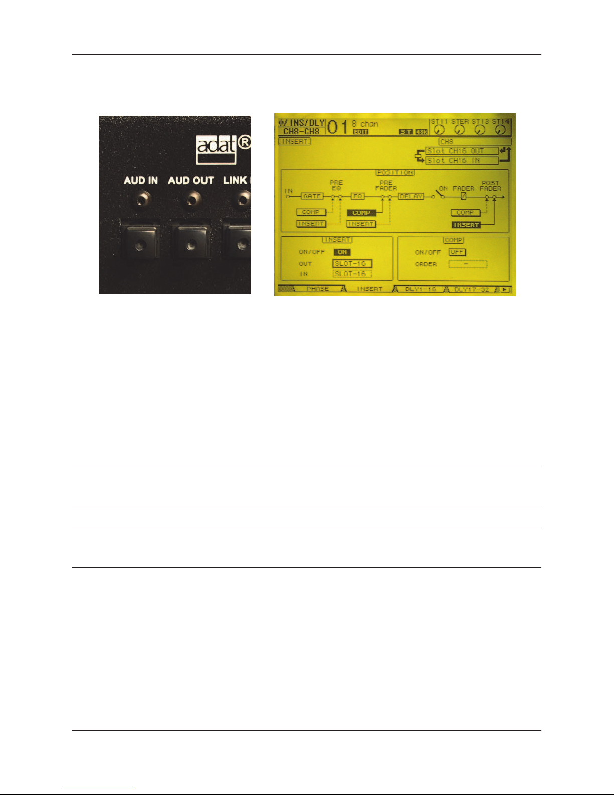
Digital I/O
Figure 2-2 Digital audio connectors (left), typical patch in Yamaha O1V96 (right)
1. Move the I/O switch on the rear panel to the DIGITAL (down) position.
2. Connect the console ADAT output to the Model E-1A AUD IN, and the Model E-1A
AUD OUT to the board’s ADAT input.
3. Using the console’s patching system, insert the ADAT inputs and outputs on each
mic channel, post-fader.
The Model E-1A can now transmit and receive eight channels to and from the
console.
If all mute buttons blink, there is no digital input signal.
NOTE: The Model E-1A (not the Model E-1) can use the LINK IN and LINK OUT connectors for
eight additional automatic mixing channels.
NOTE: Due to the Model E-1A’s compact size and close spacing of the ADAT connectors, some large
cables may not fit. The maximum cable width is 0.48 in (12 mm).
Power-up Reset Command
The Model E-1A can execute five commands during power-up. Each command is selected by holding down a specific button during the entire power-up process. Powerup is complete after the front panel LEDs stop flashing.
The most important power-up command is Reset. See
about the additional commands.
Configuration on page 20 to learn
12

Dugan Models E-1 and E-1A User Guide Quickstart
To execute a power-up Reset command, hold the channel 1 bypass button down during power-up. This sets all parameters to factory default settings and clears label text.
We recommend executing a Reset command (just like “zeroing out” a console) before
starting a new installation.
Linking Multiple Dugans
Up to eight Dugan units can be linked into a single automatic mixing system. One
unit must be set to be the master and the others slaves.
Figure 2-3 Linking multiple Dugans
1. Designate one unit as the master by setting the NORM-SLAVE switch on the rear
panel to NORM (up).
2. Designate any other units as slaves by setting their NORM-SLAVE switches on the
rear panel to SLAVE (down).
3. Use ADAT (Toslink) cables to link units in a ring network (see above).
Note that all LINK IN and OUT connectors are used to create the ring.
NOTE: Due to the Model E-1A’s compact size and close spacing of the ADAT connectors, some large
cables may not fit. The maximum cable width is 0.48 in (12 mm).
NOTE: Linked Model E-1s appear in group a only. Linked Model E-1As can use groups a–c.
13

Dugan Models E-1 and E-1A User Guide
Operation
1. Raise your console preamp gains until the Model E-1A’s green level LEDs stay illu-
minated when the room is quiet.
The level LED illuminates green when the input level is within the acceptable
range for automatic mixing and flashes red to indicate clipping. There should be
enough gain ahead of the Model E-1A to maintain the green LED at all times.
Figure 2-4 Setting console preamp gain
2. If there is insufficient gain to keep the level LEDs lit green when no one is talking,
set the rear panel LEVEL switch to -10.
The auto mix gain meters show the channel gains resulting from the process. They
are not level meters!
3. Adjust your console’s preamp gains so all LED meters float at about the same gain
when no one is talking.
Each talker now has equal access to the system gain. Note that this is not the same
as adjusting for each talker’s level.
4. Adjust the console faders to balance the talkers.
Don’t worry about the relative positions of the faders because the automixing algorithm takes care of cueing the mics in and out.
5. If your Model E-1A is inserted to the console post-fader, you are good to go.
6. If the Model E-1A is inserted pre-fader, you must use the Model E-1A’s mute but-
tons to mute mics.
With pre-fader insert patching, pulling a fader down to mute a mic leaves that
mic’s signal in the automxing process. This can cause the room ambience in the
mix to fluctuate, or in the worst case, cut off a talker.
14

Dugan Models E-1 and E-1A User Guide
Chapter 3: Installation and Configuration
Installation
We recommend placing the Model E-1A in a convenient place in the operator’s line
of sight. A typical location is the center of the console’s meter bridge.
Figure 3-1 Model E-1A placed conveniently
Rack Mounting
The Models E-1 and E-1A are each half-rack in width. They can be rack mounted as
a single unit or as a pair side-by-side. Each unit ships with one long and one short
rack ear and one joining plate.
The rack ears for Models E-1 and E-1A are different but the joining plates are the
same. Models E-1 and E-1A can be mounted side-by-side using the appropriate rack
ear for each unit.
To mount one unit, attach one long and one short rack ear. Then mount in the rack.
To mount two units side-by-side:
1. For the left unit, remove the four screws from the right side of the top and bottom
lids.
2. Attach the top and bottom joining plates to the left unit.
3. For the right unit, remove the four screws from the left side of the top and bottom
lids.
4. Attach the top and bottom joining plates to the right unit.
5. Attach the appropriate rack ears to the left and right units.
6. Mount the pair in the rack.
15

Dugan Models E-1 and E-1A User Guide
Power Supply
Units shipped to the USA include a 12 V, 1.5 A, 120 VAC power supply. Contact the
factory if you require a different power supply. In an emergency, the Model E-1A can
accept power supplies within the following ranges:
• 12–24 VDC, either polarity, 1.5 A
• 9–18 VAC, 1.5 A
Audio Wiring
The ANALOG–DIGITAL switch selects which input is active, but both outputs remain active.
Analog I/O
Set the ANALOG–DIGITAL switch to ANALOG.
The eight channel inputs and outputs are TRS insert jacks. The Model E-1A receives
signal on the Tip and sends the return from the Ring.
When the Model E-1A is off, the audio signal passes through unaltered, so the unit
may be left patched when not in use.
The Model E-1A can be connected to the insert or line level input jacks.
Figure 3-2 Analog connection
16
 Loading...