

Page 1
Ver:1.0A
Quick Start Guide for ECHO FD
ECHO FD Ultrasonic Flaw Detector
Page 2

Danatronics, Corp.
2
Liability
Ultrasonic testing is a function of using the proper equipment (electronics, transducer,
cable and couplant combination) for the inspection and a qualified operator who knows
how to use this manual, the instruments and all calibration procedures. The improper use
of this equipment, along with the improper calibration can cause serious damage to
components, factories, facilities, personal injury, and even death. ALL DANATRONICS
ULTRASONIC THICKNESS GAGES ARE NOT INTRINSICALLY SAFE AND
SHOULD NOT BE USED IN ANY HAZEDOUS OR EXPLOSIVE AREAS.
It is understood that the operator of this equipment is a well trained inspector qualified by
either their own company or another outside agency to issue Ultrasonic Level I, 40 hour
class room training in Ultrasonic Theory. Danatronics, Corp. and any of its employees or
representatives shall not be held responsible for improper use of this equipment for its
intended use. Proper training, a complete understanding of Ultrasonic wave propagation,
thorough reading of this manual, proper transducer selection, correct zeroing of the
transducer, correct sound velocity, proper test blocks, proper cable length, proper
couplant selection all play a factor in successful ultrasonic thickness gaging. Special care
should be taken when test pieces have rough or painted surfaces, particularly those
applications where the test piece is thin to begin with as doubling of the echoes is
possible even if the transducer is capable of measuring the desired thickness. As
transducers wear or heat up, results can be either too thin due to a lack of sensitivity as a
result of wear or too thick due to heating up of the transducer, referred to as “drift.”
Page 3

ECHO FD Ultrasonic Flaw Detector
3
Table of Contents
!"#$"%"&'())))))))))))))))))))))))))))))))))))))))))))))))))))))))))))))))))))))))))))))))))))))))))))))))))))))))))))))))))))))))(*!
+(,-&&"./(0&-2()))))))))))))))))))))))))))))))))))))))))))))))))))))))))))))))))))))))))))))))))))))))))))))))))))))))))(3!
4$56&(&7-(89:;(0-1"-<())))))))))))))))))))))))))))))))))))))))))))))))))))))))))))))))))))))))))))))))))))))))))))))))))))))))(3!
*(=#<">(;?-1#&"5.<()))))))))))))))))))))))))))))))))))))))))))))))))))))))))))))))))))))))))))))))))))))))))))))))))))))))(@!
A5B-1(;.(&7-(C."&()))))))))))))))))))))))))))))))))))))))))))))))))))))))))))))))))))))))))))))))))))))))))))))))))))))))))))))))(@!
D-'?#2(E6.>&"5.<())))))))))))))))))))))))))))))))))))))))))))))))))))))))))))))))))))))))))))))))))))))))))))))))))))))))))))))))(F!
=#&&-1'(A#>G())))))))))))))))))))))))))))))))))))))))))))))))))))))))))))))))))))))))))))))))))))))))))))))))))))))))))))))))))))))))(H!
I5."&51"./(&7-(=#&&-1'(97#1/-(J15K(&7-(L"<?%#'(0>1--.())))))))))))))))))))))))))))))))))))))))))))))))))))))(H!
M-N>7#1/"./(&7-(=#&&-1'()))))))))))))))))))))))))))))))))))))))))))))))))))))))))))))))))))))))))))))))))))))))))))))))))))))))(O!
C<"./(P5.N1->7#1/-#$%-(44(=#&&-1"-<()))))))))))))))))))))))))))))))))))))))))))))))))))))))))))))))))))))))))))))))))(+Q!
=55&R(=#"%R(#.2(0&1#?(E-#&61-<())))))))))))))))))))))))))))))))))))))))))))))))))))))))))))))))))))))))))))))))))))))))))))(+Q!
A%#>"./(&7-(=55&(5.(&7-(C."&()))))))))))))))))))))))))))))))))))))))))))))))))))))))))))))))))))))))))))))))))))))))))))))))(++!
M-K5S"./(&7-(=55&(J15K(&7-(C."&()))))))))))))))))))))))))))))))))))))))))))))))))))))))))))))))))))))))))))))))))))))))(++!
C<"./(&7-(=55&(0&1#?(#.2(=#"%()))))))))))))))))))))))))))))))))))))))))))))))))))))))))))))))))))))))))))))))))))))))))))))(++!
;&7-1(C."&(E-#&61-<())))))))))))))))))))))))))))))))))))))))))))))))))))))))))))))))))))))))))))))))))))))))))))))))))))))))))))(++!
C<"./(&7-(TUM(+(#.2(TUM(*(A51&<())))))))))))))))))))))))))))))))))))))))))))))))))))))))))))))))))))))))))))))))))))))))))(++!
!5>#&"./(&7-(C0=(0%5&()))))))))))))))))))))))))))))))))))))))))))))))))))))))))))))))))))))))))))))))))))))))))))))))))))))))))(++!
C<"./(&7-(4>>-<<51'(I56.&())))))))))))))))))))))))))))))))))))))))))))))))))))))))))))))))))))))))))))))))))))))))))))))))(++!
!5>#&"./(&7-(4%&"&62-(97#./-(M-%-#<-(M-/6%#&51()))))))))))))))))))))))))))))))))))))))))))))))))))))))))))))))))(++!
89:;(EL(C<-1(V.&-1J#>-())))))))))))))))))))))))))))))))))))))))))))))))))))))))))))))))))))))))))))))))))))))))))))))))))))))(++!
A#1#K-&-1(;S-1S"-B())))))))))))))))))))))))))))))))))))))))))))))))))))))))))))))))))))))))))))))))))))))))))))))))))))))))))(+3!
Gain!......................................................................................................................................!15!
Frequency!............................................................................................................................!15!
Measurement!Mode!............................................................................................................!16!
Reject!...................................................................................................................................!16!
Rectification!.........................................................................................................................!16!
Gate!1!Start!................................ ..........................................................................................!17!
Gate!1!Width!........................................................................................................................!17!
Gate!1!Level!.........................................................................................................................!18!
Gate!1!Alarm!........................................................................................................................!18!
Gate!1!Auto!80!.....................................................................................................................!18!
Gate!2!Start!................................ ..........................................................................................!19!
Gate!2!Width!........................................................................................................................!19!
Gate!2!Level!.........................................................................................................................!20!
Gate!2!Alarm!........................................................................................................................!20!
Gate!2!Auto!80!.....................................................................................................................!20!
Zero!......................................................................................................................................!21!
Velocity!................................................................................................................................!21!
Angle!....................................................................................................................................!22!
Thickness!..............................................................................................................................!22!
Energy!..................................................................................................................................!22!
DAC!......................................................................................................................................!23!
Curve!....................................................................................................................................!23!
DAC!Gain!..............................................................................................................................!24!
Range!...................................................................................................................................!24!
Page 4

Danatronics, Corp.
4
Delay!....................................................................................................................................!24!
Gate!1!Detection!..................................................................................................................!25!
Gate!2!Detection!..................................................................................................................!25!
Measurement!Box!2!.............................................................................................................!25!
Measurement!Box!3!.............................................................................................................!26!
Measurement!Box!1!.............................................................................................................!26!
ID!..........................................................................................................................................!26!
Peak!Memory!.......................................................................................................................!27!
L"<?%#'(0>1--.())))))))))))))))))))))))))))))))))))))))))))))))))))))))))))))))))))))))))))))))))))))))))))))))))))))))))))))))))))(*F!
I5."&51"./(&7-(=#&&-1'(97#1/-(J15K(&7-(L"<?%#'(0>1--.()))))))))))))))))))))))))))))))))))))))))))))))))))))(*O!
W(9#%"$1#&"./(&7-(89:;(EL(J51(95.&#>&(T1#.<26>-1<())))))))))))))))))))))))))))))))))))))))))))))))))))(WQ!
X-%5>"&'(9#%"$1#&"5.(;.%'())))))))))))))))))))))))))))))))))))))))))))))))))))))))))))))))))))))))))))))))))))))))))))))))))))(W+!
Y(89:;(EL(9#%"$1#&"5.<())))))))))))))))))))))))))))))))))))))))))))))))))))))))))))))))))))))))))))))))))))))))))))))(W*!
4./%-(=-#K(9#%"$1#&"5.())))))))))))))))))))))))))))))))))))))))))))))))))))))))))))))))))))))))))))))))))))))))))))))))))))))(WY!
0-&&"./(M-J-1-.>-(,#".()))))))))))))))))))))))))))))))))))))))))))))))))))))))))))))))))))))))))))))))))))))))))))))))))))))))(WH!
0-&&"./(M-J(,#".(0&-?())))))))))))))))))))))))))))))))))))))))))))))))))))))))))))))))))))))))))))))))))))))))))))))))))))))))))(WO!
3(8>75(EL(#2S#.>-2(<5J&B#1-(J-#&61-<()))))))))))))))))))))))))))))))))))))))))))))))))))))))))))))))))))))))(YQ!
4Z0(LN1#&"./())))))))))))))))))))))))))))))))))))))))))))))))))))))))))))))))))))))))))))))))))))))))))))))))))))))))))))))))))))))(YQ!
0-&&"./(,#&-(4%#1K<())))))))))))))))))))))))))))))))))))))))))))))))))))))))))))))))))))))))))))))))))))))))))))))))))))))))))))(Y+!
A5<"&"S-(,#&-(4%#1K())))))))))))))))))))))))))))))))))))))))))))))))))))))))))))))))))))))))))))))))))))))))))))))))))))))))))))(Y+!
P-/#&"S-(,#&-(4%#1K())))))))))))))))))))))))))))))))))))))))))))))))))))))))))))))))))))))))))))))))))))))))))))))))))))))))))(Y*!
I"."K6K(L-?&7(4%#1K()))))))))))))))))))))))))))))))))))))))))))))))))))))))))))))))))))))))))))))))))))))))))))))))))))))))(Y*!
0&51-2(<-&6?<()))))))))))))))))))))))))))))))))))))))))))))))))))))))))))))))))))))))))))))))))))))))))))))))))))))))))))))))))))))(YW!
L49([L"<&#.>-(4K?%"&62-(9511->&"5.(961S-<\(,CV()))))))))))))))))))))))))))))))))))))))))))))))))))))))))))))))(Y3!
@(T->7.">#%(4<<"<&#.>-()))))))))))))))))))))))))))))))))))))))))))))))))))))))))))))))))))))))))))))))))))))))))))))))(YF!
Page 5

ECHO FD Ultrasonic Flaw Detector
5
1 Getting Started
About the ECHO Series
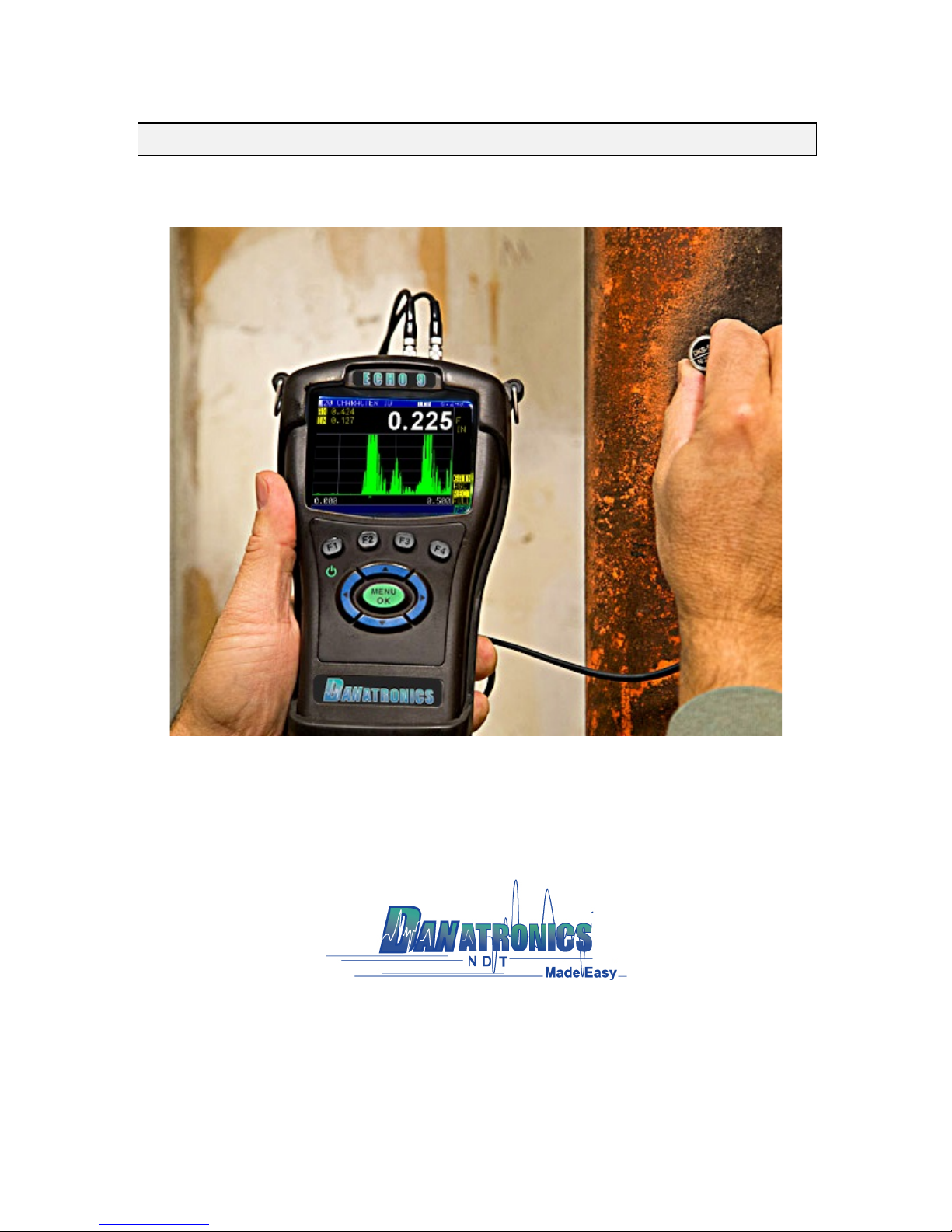
ECHO FD is a portable ultrasonic flaw detector in the same field-proven case as our
popular ECHO series, and it represents a breakthrough in terms of cost, size, ease of use,
and versatility. ECHO FD can even toggle from an every day flaw detector to a corrosion
or precision thickness gage making it the smallest and most affordable unit in the world
to offer such a vast application set. Our new hand-held ultrasonic flaw detector is packed
with many useful and practical features including:
Ø 3.5" sunlight readable display with color pallet
Ø Change color and vibrate on alarm
Ø 2 independent gates
Ø DAC
Ø AWS
Ø API-5UE
Ø Peak Memory
Ø 2GB, expandable to 32GB, micro SD card memory
Ø Datalogger including B-scan and export of reading to excel
Ø 13 hour battery life
Ø Custom rubber boot with padded wrist strap and bail
Ø Made and designed in the USA
Page 6
Danatronics, Corp.
6
2 Basic Operations
Make sure the connector is plugged into TR 2 when using a single element probe.
Power On the Unit
To power on any ECHO FD, follow these steps:
1. Press and hold the F1 key for more than 3 seconds. The power symbol, as shown
below, is under the F1 key printed on the keypad.
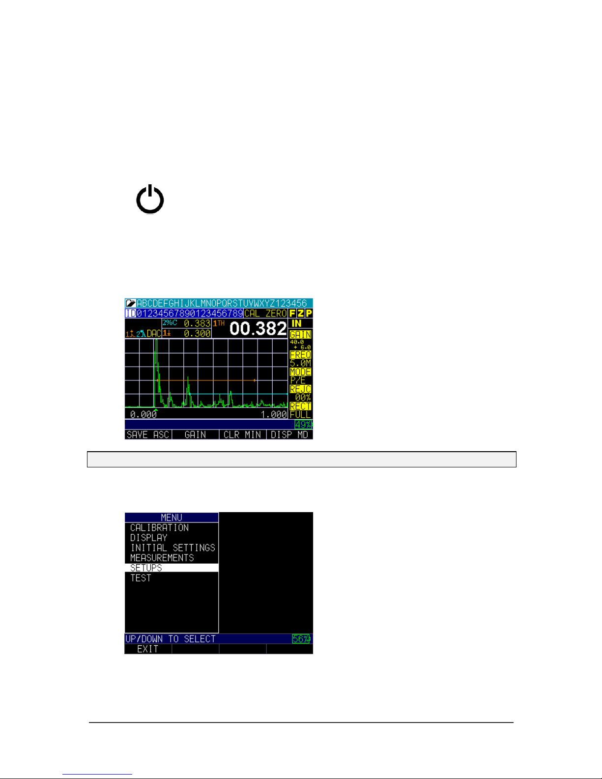
2. After powering on the ECHO FD, the unit will display the last instrument settings
as well as the battery life in the bottom right corner. The image below shows the
battery life at 49%.
Note: Set your parameters based on the type of probe you are using.
3. Press the MENU/OK key and use the up and down arrow keys to select the
Setups option. Press the MENU/OK key again.
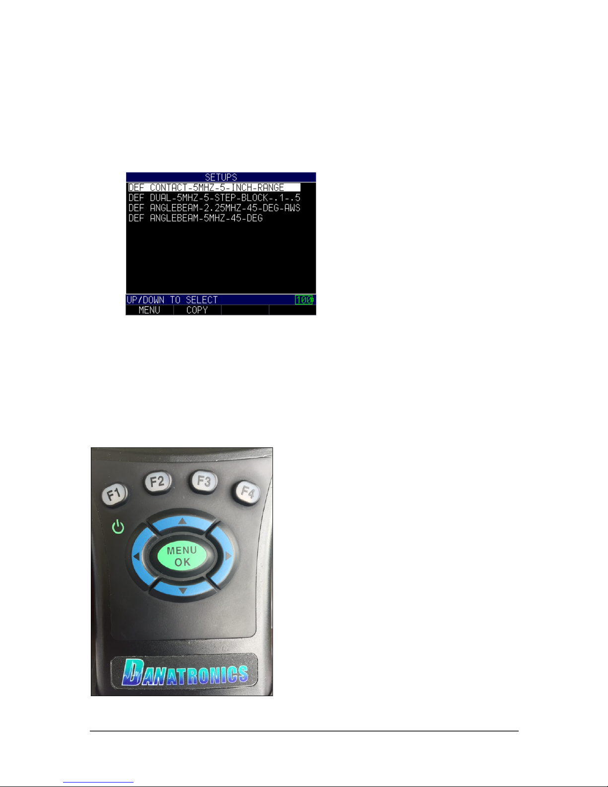
4. In the Setups menu, use the up and down arrow keys to select the probe closest to
the one you will be using. If none of the options are close, then press the F1 –
Exit key to set your own parameters.
Power symbol
under the F1 key
Page 7
ECHO FD Ultrasonic Flaw Detector
7
ECHO FD has 4 default setup template files that cannot be deleted. They are as follows:
1. Straight beam contact probe 5 MHz, 5" range
2. Dual probe 5 MHz on a 0.100-0.500" (2.52-12.7mm) test block
3. Angle beam AWS type 2.25 with ref gain on
4. Angle beam quick change 5 MHz, 45 degree
To get started, we recommend that you choose a setup close to what you will be using.
This will allow you to get echoes and make smaller adjustments when fine-tuning your
setups and calibrations. As stated, the default setups cannot be deleted. Once a new
custom setup is saved (1,800 max.), you can also use the included Data XL interface
program to save them on your computer and even send the setups to additional ECHO
FDs.
Keypad Functions
The figure below shows the full keypad layout representative of each ECHO series unit.
Page 8
Danatronics, Corp.
8
The following table refers to each key or symbol shown on the keypad. Note, the F keys
correspond to text above each key and prompts change depending on which screen you
are adjusting.
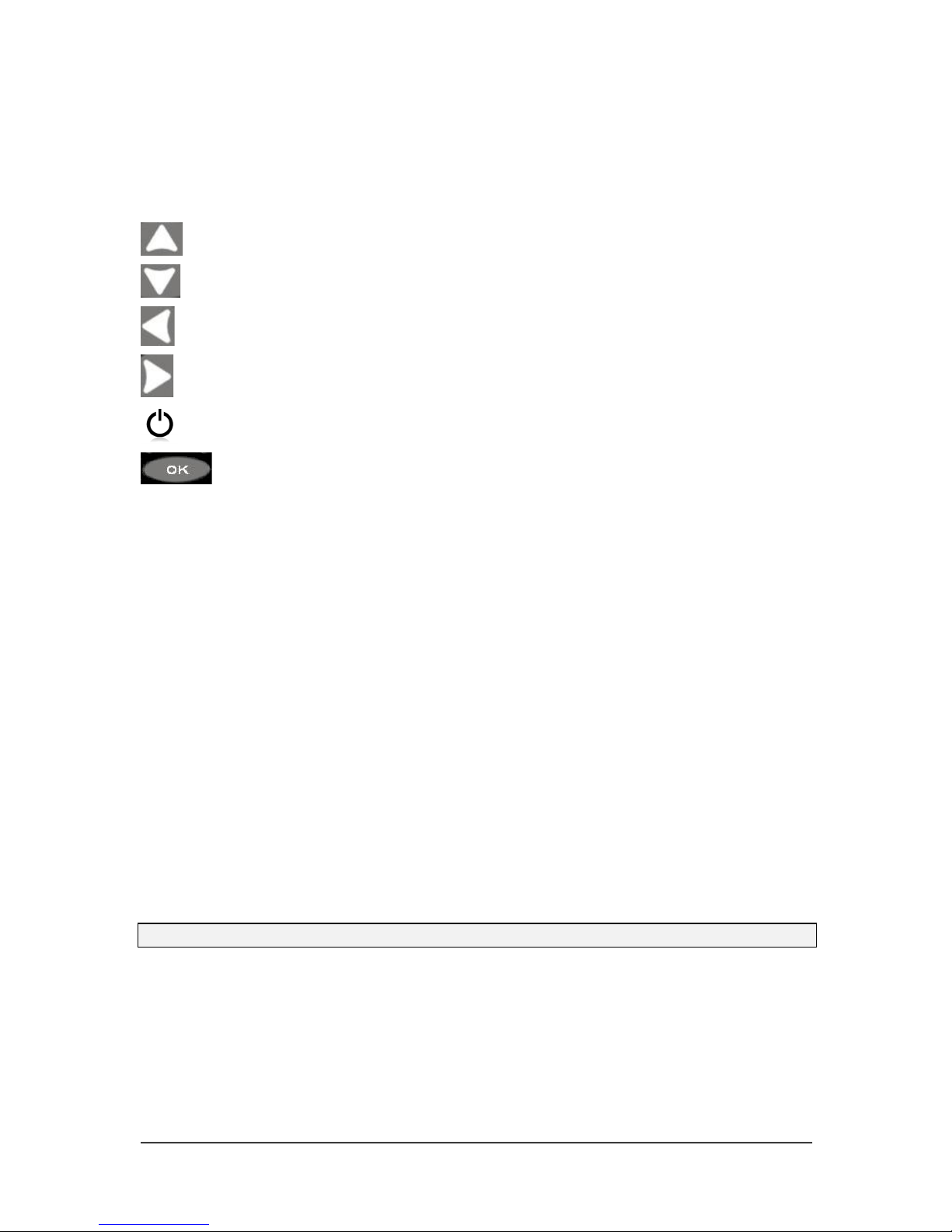
Key
Function
Up arrow key
Down arrow key
Left arrow key
Right arrow key
On/Off symbol (under the F1 key)
MENU/OK key
F1
Varies
F2
Varies
F3
Varies
F4
Varies
Function keys, or F keys (e.g., F1, F2, F3, F4), have various unit functions and may
change depending on the display screen. View the bottom of the display screen for the
function that corresponds with the appropriate F key. For example, F1 may correspond
with the Save function, F2 with the Freeze function, or F3 with the Directory function
Battery Pack
To ensure the highest level of performance and protection, the battery compartment is
separated from the electronic components of the unit.
Monitoring the Battery Charge from the Display Screen
The ECHO unit continuously displays the percentage of battery life remaining on the
bottom right corner of the measurement display screen. When the battery life is below
10%, the battery indicator will turn from green to red. When the battery life is below 5%,
the indicator will flash.
Note: Power off the ECHO unit to ensure any saved data is stored internally.
Page 9
ECHO FD Ultrasonic Flaw Detector
9
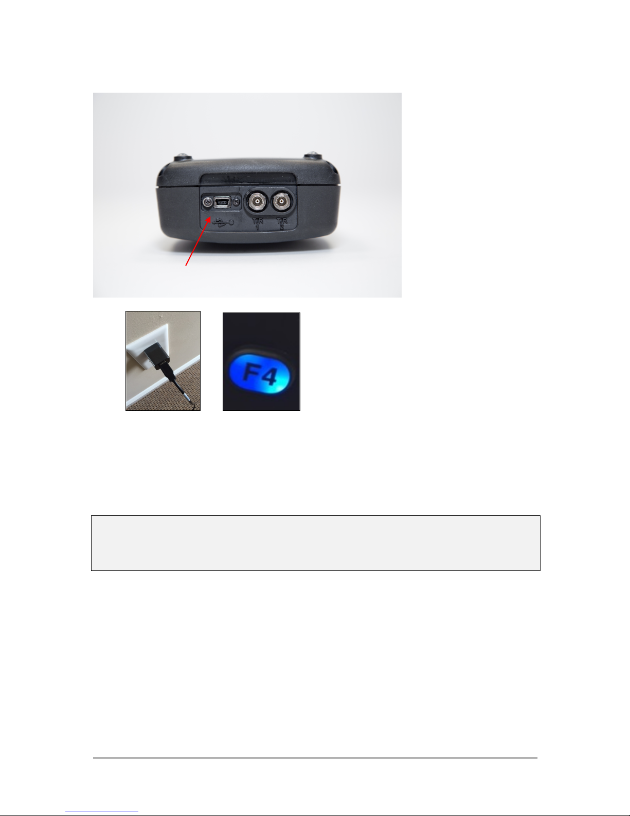
Re-charging the Battery
To re-charge the battery, simply plug in the charger to an AC outlet (between 100-240V)
and plug the other end into the USB connector on the top of the ECHO series unit. The
F4 key will light up with a blue LED when charging, and the light will go out when fully
charged. Allow several hours (up to 10 hours) to fully charge. We recommend using the
charger and high-quality USB cable that is supplied with the ECHO unit. Using lower
quality USB cables can result in little or no charge.
Note: It is possible to use a computer to charge the unit, but this will take significantly
more time than using an AC outlet and we do not recommend it; however, if you decide
to charge the flaw detector using this method, make sure the unit is powered off before
you connect the USB to the computer and to the flaw detector itself.
When charging is complete, the F4 key will appear translucent in color. Power off the
flaw detector, and unplug the charger from the USB connector on the top of the unit.
Keep in mind, there is a battery indication monitor on the bottom right of the screen that
displays the percentage of battery life, as shown in the image below at 71%.
USB port
Page 10

Danatronics, Corp.
10
Using Non-rechargeable AA Batteries
A non-rechargeable alkaline AA pack is also available. This option requires a spare tray
and 3 AA batteries. Follow these steps to insert non-rechargeable batteries:
1. Un-screw the battery door.
2. Disconnect the Li-Ion battery connector.
3. Plug in the AA tray connector.
4. Replace the battery door and tighten screws.
Note: When using the 3 AA battery tray, batteries cannot be re-charged.
Boot, Bail, and Strap Features
The custom rubber boot with built in bail and 4-point chest harness is an accessory for all
ECHO series units. Not only does the boot help to protect the unit from the elements, but
the functional bail and strap also offers a variety of positioning options.
Page 11

ECHO FD Ultrasonic Flaw Detector
11
Placing the Boot on the Unit
To insert the unit into the rubber boot, follow these steps:
1. Guide the unit strap through the hole at the top of the boot (either right or left
side).
2. Slide the unit into the top of the boot.
3. Gently apply pressure to the bottom of the unit until it fully pops into the boot.
Removing the Boot from the Unit
Be sure that the bail is set in the open position before attempting to remove the boot.
Follow these steps:
1. Apply pressure to the bottom two corners of the boot until the unit pops out.
2. Wriggle the top section of the unit out of the boot.
3. Guide the unit strap through the hole at the top of the boot.
Using the Boot Strap and Bail
The boot strap is attached to the bail on the back of the boot. It can be used as a right- or
left-handed strap, or a finger strap. You can also connect the strap to a 4-point chest
harness for hands-free use.
The bail, including the straps, can be removed from the boot. This is useful when adding
accessories or locating the unit’s serial number. Simply open the bail and apply gentle
pressure to one side of the connector, which is located at the top of the bail. The piece
will pop off exposing the accessory mount (see below) and unit serial number.
Other Unit Features
Using the T/R 1 and T/R 2 Ports
On the top of the ECHO series units are two ports for transducer connectivity.
If you are using a dual element transducer, you may use either port—T/R 1 or T/R 2—
interchangeably. However, if you are using a single element transducer, plug the
connector into the T/R 1 port only.
Locating the USB Slot
The ECHO series units are furnished with a USB 2.0 slot on the top of the unit. Use the
USB slot to connect AC chargers or to connect to a computer for cross-functionality.
Using the Accessory Mount
On the back of the unit is a ¼ x 20 accessory mount. This connector point is compatible
with a multitude of accessories including a magnetic pipe attachment and a Gorilla Pod.
Locating the Altitude Change Release Regulator
At the bottom of the unit is a circular outline with small holes. This feature regulates
pressure due to altitude change. Any pressure built up inside the unit will be
automatically released.
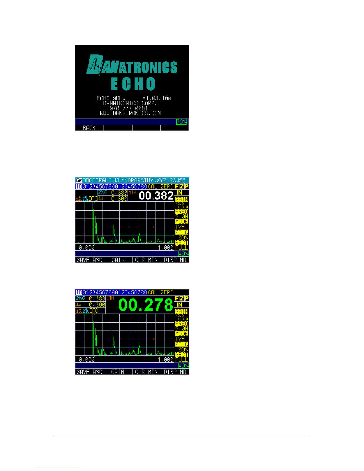
ECHO FD User Interface
Press and hold the F1 key to power on the unit. The following Display screen will appear
for 5 seconds.
Page 12
Danatronics, Corp.
12
Display screen shows remaining battery life
The Measurement screen will appear following the Display screen. There are five
Measurement screens as shown below. Use the F4 – DISP MD key to toggle the screen
between display modes.
Display Mode 1
Display Mode 2
Page 13
ECHO FD Ultrasonic Flaw Detector
13
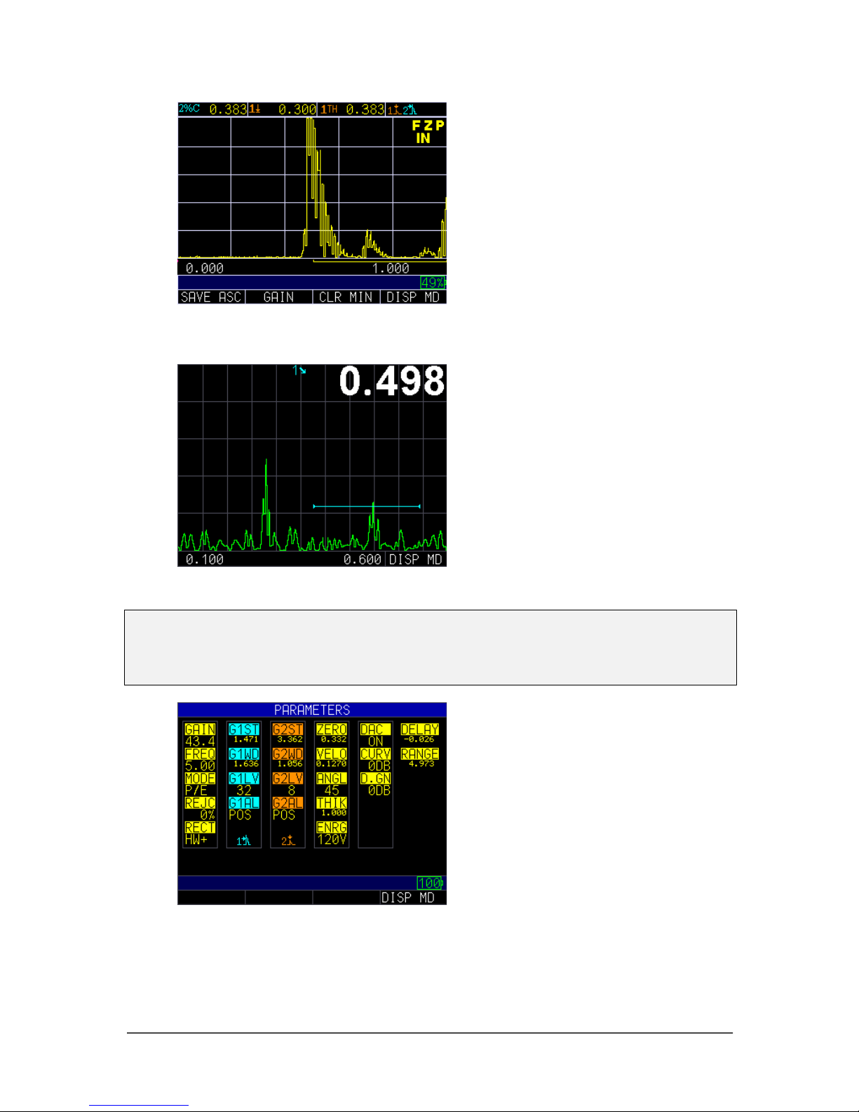
Display Mode 3
Display Mode 4 (Scan Mode)
Note: You cannot use the left or right arrow keys to edit any parameter in the scanning
mode screen. The parameter in the large measurement box (e.g., soundpath
measurement of 0.498" shown above) will be displayed in the top right corner of the
screen. To change a parameter, press the F4 – DISP MD key.
Display Mode 5
Similar to ECHO 9 and ECHO 7, the left and right arrow keys will activate editing of the
parameters. A parameter that is highlighted will be active to edit by using the up and
down arrow keys. The right arrow key will select parameters in a clockwise direction and
Page 14
Danatronics, Corp.
14
the left arrow key will select parameters in a counter clockwise direction. Red-circled
parameters, shown below, will be editable. This screen also represents the default screen
because it allows full instrument operation while showing the largest A-scan. This screen
will appear 10 seconds after the Parameter screen is displayed upon powering on the
unit. To change the Display mode, simply press the F4 – DISP MD key.
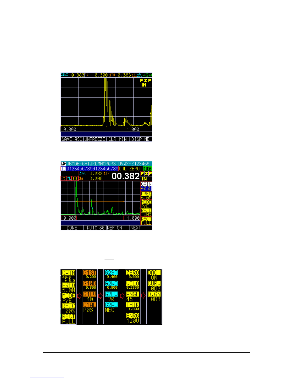
Color Waveform in Echo-to-Echo mode, filename, ID, thickness value, gain, rectification, battery
life, alarm, freeze, backlight, and display mode.
Press the left or right arrow key to activate the Parameter Edit mode. Once active, you
can scroll through the list using the left or right arrow key and then use the up and down
arrow keys to make adjustments. When finished, press the F1 – Done key to end editing
or the F4 key to select the next set of parameters. The list will toggle the right side
parameter list in following order:
Page 15
ECHO FD Ultrasonic Flaw Detector
15
Parameter Overview
ECHO FD Ultrasonic Flaw Detector has many parameters that can be edited by using the
functions keys. Note, the function keys will vary depending on the current screen in use.
Below is an overview of editable parameters for ECHO FD and how the function keys
work for each relevant screen.
Note: Some of the below F1, F2, F3 and F4 screen shots are subject to change with
software updates.
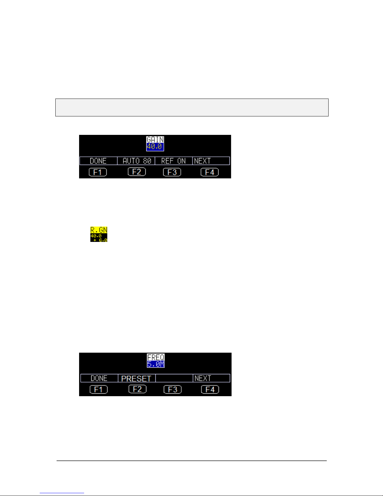
Gain
• F1: Done (exit edit mode)
• F2: Gate 1 Auto 80 – set signal within Gate 1 amplitude to 80% by adjusting
gain automatic
• F3: Toggle Ref Gain On/Off. If Ref Gain is active, then Ref Gain and
Scanning Gain will appear as follows:
Also F2 will become ADD. In this situation when F2 is pressed, Ref Gain and
Scanning Gain will be added and Scanning Gain will be deactivated.
• F4: Next page of Gate 1 parameters
• Up/Down Arrow: Slew gain from 0.0 dB to 90.0 dB, and if Ref Gain is
active, the Up/Down arrow keys will slew Scanning Gain
• Right Arrow: Select Scanning Gain if Ref Gain is selected, or select Freq to
edit if Scanning Gain is selected
• Left Arrow: Select Peak to edit if you are in Gain or Ref Gain and if
Scanning Gain is selected
• MENU/OK: Go to Menu to set the Gain parameters
Frequency
• F1: Done (exit edit mode)
• F2: Cycle through fixed list of frequencies: 1.0M, 2.2M, 5.0M, 7.5M, 10.0M,
12.0M
• F3: None
• F4: Next page of Gate 1 parameters
Page 16

Danatronics, Corp.
16
• Up/down Arrow: Slew frequency from 1.0MHz to 12.0 MHz
• Right Arrows: Select Measurement mode to edit
• Left Arrows: If Ref Gain is on, then select Scanning Gain or else select Gain
to edit
• MENU/OK: Go to Menu to set the Frequency parameters
Measurement Mode
• F1: Done (exit edit mode)
• F2: None
• F3: None
• F4: Next page of Gate 1 parameters
• Up/Down Arrow: Cycle thru P/E, THRU, DUAL
• Right Arrow: Select Reject to edit
• Left Arrow: Select Frequency to edit
• MENU/OK: Go to Menu to set Measurement mode parameters
Reject
• F1: Done (exit edit mode)
• F2: None
• F3: None
• F4: Next page of Gate 1 parameters
• Up/Down Arrow: Slew 0 to 85%
• Right Arrow: Select Rectification to edit
• Left Arrow: Select Mode to edit
• MENU/OK: Go to Menu to set Reject parameters
Rectification
• F1: Done (exit edit mode)
Page 17

ECHO FD Ultrasonic Flaw Detector
17
• F2: None
• F3: None
• F4: Next page of Gate 1 parameters
• Up/Down Arrow: Cycle thru FULL, HW+, HW-, RF
• Right Arrow: Select Range to edit
• Left Arrow: Select Reject to edit
• MENU/OK: Go to Menu to set Rectification parameters
Gate 1 Start
• F1: Done (exit edit mode)
• F2: None
• F3: None
• F4: Next page of Gate 2 parameters
• Up/Down Arrow: Slew Gate 1 Start value from Delay up to (Delay + Current
Range)
• Right Arrow: Select Gate 1 Width to edit
• Left Arrow: Select Peak to edit
• MENU/OK: Go to Menu to set Gate 1 Start parameters
Gate 1 Width
• F1: Done (exit edit mode)
• F2: None
• F3: None
• F4: Next page of Gate 2 parameters
• Up/Down Arrow: Slew Gate 1 Width value from 0.010" to (Delay + Current
Range)
• Right Arrow: Select Gate 1 Level to edit
• Left Arrow: Select Gate 1 Start to edit
• MENU/OK: Go to Menu to set Gate 1 Width parameters
Page 18

Danatronics, Corp.
18
Gate 1 Level
• F1: Done (exit edit mode)
• F2: None
• F3: None
• F4: Next page of Gate 1 parameters
• Up/Down Arrow: Slew Gate 1 Level value from 2% to 95%
• Right Arrow: Select Gate 1 Alarm to edit
• Left Arrow: Select Gate 1 Width to edit
• MENU/OK: Go to Menu to set Gate 1 Level parameters
Gate 1 Alarm
• F1: Done (exit edit mode)
• F2: None
• F3: None
• F4: Next page of Gate 2 parameters
• Up/Down Arrow: Toggle options: OFF, POS, NEG, MIN DEPTH if DAC is
inactive
OFF, POS, NEG, MIN DEPTH, ASME if DAC = ASME
OFF, POS, NEG, MIN DEPTH, 0 dB, -6 dB, -14 dB if
DAC = ASME3
OFF, POS, NEG, MIN DEPTH, RL, SL, EL if DAC =
CUSTOM
• Right Arrow: Select Gate 1 Auto 80 to set
• Left Arrow: Select Gate 1 Level to edit
• MENU/OK: Go to Menu to set Gate 1 Alarm parameters
Gate 1 Auto 80
Page 19

ECHO FD Ultrasonic Flaw Detector
19
• F1: Done (exit edit mode)
• F2: Perform Auto 80
• F3: None
• F4: Next page of Gate 2 parameters
• Up/Down Arrow: None
• Right Arrow: Select Range to set
• Left Arrow: Select Gate 1 Alarm to edit
• MENU/OK: None
Gate 2 Start
• F1: Done (exit edit mode)
• F2: None
• F3: G2 OFF or ON
• F4: Next page of parameters
• Up/Down Arrow: Slew Gate 2 Start value from Delay up to (Delay + Current
Range)
• Right Arrow: Select Gate 2 Width to edit
• Left Arrow: Select Peak to edit
• MENU/OK: Go to Menu to set Gate 2 Start parameters
Gate 2 Width
• F1: Done (exit edit mode)
• F2: None
• F3: G2 OFF or ON
• F4: Next page of Parameters
• Up/Down Arrow: Slew Gate 2 Width value from 0.010" to (Delay + Current
Range)
• Right Arrow: Select Gate 2 Level to edit
• Left Arrow: Select Gate 2 Start to edit
• MENU/OK: Go to Menu to set Gate 2 Width parameters
Page 20

Danatronics, Corp.
20
Gate 2 Level
• F1: Done (exit edit mode)
• F2: None
• F3: G2 OFF or ON
• F4: Next page of parameters
• Up/Down Arrow: Slew Gate 2 Level value from 2% to 95%
• Right Arrow: Select Gate 2 Alarm to edit
• Left Arrow: Select Gate 2 Width to edit
• MENU/OK: Go to Menu to set Gate 2 Level parameters
Gate 2 Alarm
• F1: Done (exit edit mode)
• F2: None
• F3: G2 OFF or ON
• F4: Next page of parameters
• Up/Down Arrow: Toggle options: OFF, POS, NEG, MIN DEPTH if DAC is
OFF
OFF, POS, NEG, MIN DEPTH, ASME if DAC = ASME
OFF, POS, NEG, MIN DEPTH, 0 dB, -6 dB, -14 dB if
DAC = ASME3
OFF, POS, NEG, MIN DEPTH, RL, SL, EL if DAC =
CUSTOM
• Right Arrow: Select Gate 2 Auto 80 to set
• Left Arrow: Select Gate 2 Level to edit
• MENU/OK: Go to Menu to set Gate 1 Alarm parameters
Gate 2 Auto 80
Page 21

ECHO FD Ultrasonic Flaw Detector
21
• F1: Done (exit edit mode)
• F2: Perform Auto 80
• F3: G2 OFF or ON
• F4: Next page of parameters
• Up/Down Arrow: None
• Right Arrow: Select Range to set
• Left Arrow: Select Gate 2 Alarm to edit
• MENU/OK: None
Zero
• F1: Done (exit edit mode)
• F2: None
• F3: None
• F4: Next page of parameters
• Up/Down Arrow: Slew Zero from 0.000" to 20.000"
• Right Arrow: Select Velocity to set
• Left Arrow: Select Peak to edit
• MENU/OK: Go to Menu to set Zero parameters
Velocity
• F1: Done (exit edit mode)
• F2: Display list of material to pick a material velocity
• F3: None
• F4: Next page of parameters
• Up/Down Arrow: Slew Velocity from 0.0800 in/us to .3000 in/us
• Right Arrow: Select Angle to set
• Left Arrow: Select Zero to edit
• MENU/OK: Go to Menu to set Velocity parameters
Page 22

Danatronics, Corp.
22
Angle
• F1: Done (exit edit mode)
• F2: Toggle through preset values 30, 45, and 60 degrees
• F3: None
• F4: Next page of parameters
• Up/Down Arrow: Slew Angle from 0 to 85 degrees
• Right Arrow: Select Thickness to set
• Left Arrow: Select Velocity to edit
• MENU/OK: Go to Menu to set Angle parameters
Note: When angle is other than Zero, ECHO FD will automatically set the acoustic
velocity to shear wave at 0.1270 in/usec and set the 3 measurement screens for Gate 1
as follows: Large box is soundpath, other boxes will be depth and surface distance.
When angle is re-set to 0 degrees, velocity will revert back to Longitudinal or 0.2330
in/usec and the large measurement box will be set to thickness.
Thickness
• F1: Done (exit edit mode)
• F2: None
• F3: None
• F4: Next page of parameters
• Up/Down Arrow: Slew Thickness from 0.020" to 20.000"
• Right Arrow: Select Energy to set
• Left Arrow: Select Angle to edit
• MENU/OK: Go to Menu to set Thickness parameters
Energy
• F1: Done (exit edit mode)
• F2: Toggle through preset values 30, 60, 90, and 120 Volts
Page 23

ECHO FD Ultrasonic Flaw Detector
23
• F3: None
• F4: Next page of parameters
• Up/Down Arrow: Toggle thru preset values 30, 60, 90, and 120 Volts
• Right Arrow: Select Range to set
• Left Arrow: Select Thickness to edit
• MENU/OK: Go to Menu to set Energy parameters
DAC
• F1: Done (exit edit mode)
• F2: Turn Off DAC
• F3: Erase DAC curve(s)
• F4: Next page of parameters
• Up/Down Arrow: Toggle between ON and OFF
• Right Arrow: Select DAC curve to set
• Left Arrow: Select PEAK mem to edit
• MENU/OK: Go to Menu to set DAC parameters
Curve
• F1: Done (exit edit mode)
• F2: None
• F3: None
• F4: Next page of parameters
• Up/Down Arrow: Toggle between Curve for ASME-3 and Custom
• Right Arrow: Select DAC Gain to set
• Left Arrow: Select DAC On/Off to edit
• MENU/OK: Go to Menu to select DAC Curve parameters
Page 24

Danatronics, Corp.
24
DAC Gain
• F1: Done (exit edit mode)
• F2: None
• F3: None
• F4: Next page of parameters
• Up/Down Arrow: Slew DAC gain
• Right Arrow: Select Range to edit
• Left Arrow: Select DAC Curve to edit
• MENU/OK: Go to Menu to edit DAC Gain parameters
Range
• F1: Done (exit edit mode)
• F2: Preset – IT will toggle through preset values 0.100", 0.200", 0.500",
1.000", 2.000", 5.000", 10.000", 20.000" and equivalent in mm and uSec
mode
• F3: None
• F4: Next page of parameters
• Up/Down Arrow: Slew Range from 0.100" to 23" in 0.001" resolution and
equivalent in mm and uSec mode
• Right Arrow: Select Delay to edit
• Left Arrow: Select last parameter of current Parameter page to edit
• MENU/OK: Go to Menu to edit Range parameters
Delay
• F1: Done (exit edit mode)
Page 25

ECHO FD Ultrasonic Flaw Detector
25
• F2: None
• F3: None
• F4: Next page of parameters
• Up/Down Arrow: Slew Delay from 0.0" to 20" in 0.001" resolution and
equivalent in mm and uSec mode
• Right Arrow: Select Gate 1 Detection mode to edit
• Left Arrow: Select Range to edit
• MENU/OK: Go to Menu to edit Delay parameters
Gate 1 Detection
• F1: Done (exit edit mode)
• F2: None
• F3: None
• F4: Next page of parameters
• Up/Down Arrow: Toggle between Edge and Peak
• Right Arrow: Select Gate 2 Detection mode to edit
• Left Arrow: Select Delay to edit
• MENU/OK: Go to Menu to edit Gate 1 Detection mode parameters
Gate 2 Detection
• F1: Done (exit edit mode)
• F2: None
• F3: None
• F4: Next page of parameters
• Up/Down Arrow: Toggle between Edge and Peak
• Right Arrow: Select Measurement Box 2 to edit
• Left Arrow: Select Gate 1 Detection mode to edit
• MENU/OK: Go to Menu to edit Gate 2 Detection mode parameters
Measurement Box 2
• F: Done (exit edit mode)
Page 26

Danatronics, Corp.
26
• F2: None
• F3: None
• F4: Next page of parameters
• Up/Down Arrow: Cycle through list of measurements
• Right Arrow: Select Measurement Box 3 to edit
• Left Arrow: Select Gate 2 Detection mode to edit
• MENU/OK: Go to Menu to edit Measurement Box 2 parameters
Measurement Box 3
• F1: Done (exit edit mode)
• F2: None
• F3: None
• F4: Next page of parameters
• Up/Down Arrow: Cycle through list of measurements
• Right Arrow: Select Measurement Box 1 to edit
• Left Arrow: Select Measurement Box 2 to edit
• MENU/OK: Go to Menu to edit Measurement Box 3 parameters
Measurement Box 1
• F1: Done (exit edit mode)
• F2: None
• F3: None
• F4: Next page of parameters
• Up/Down Arrow: Cycle through list of measurements
• Right Arrow: Select ID to edit
• Left Arrow: Select Measurement Box 3 to edit
• MENU/OK: Go to Menu to edit Measurement Box 1 parameters
ID
• F1: Done (exit edit mode)
• F2: None
Page 27

ECHO FD Ultrasonic Flaw Detector
27
• F3: None
• F4: Next page of parameters
• Up/Down Arrow: Cycle through IDs
• Right Arrow: Select Peak Memory to edit
• Left Arrow: Select Measurement Box 1 to edit
• MENU/OK: Go to Menu to edit ID parameters
Peak Memory
• F: Done (exit edit mode)
• F2: None
• F3: None
• F4: Next page of parameters
• Up/Down Arrow: Toggle between Peak, Peak Hold, and OFF
• Right Arrow: Select 1st parameter of current Parameter page to edit
• Left Arrow: Select ID to edit
• MENU/OK: Go to Menu to edit Peak Memory parameters
Display Screen
ECHO FD has a graphic-style color display with 320 x 240 (1/4 VGA) pixel density.
Viewing the screen is best from straight above or slightly below the surface rather than
from side to side. If external temperature is below 32°F (0°C), the display may be slower
to update information.
Color thickness reading only on ECHO 9
Page 28

Danatronics, Corp.
28
Color Waveform in Echo-to-Echo mode, filename, ID, thickness value, gain, rectification, battery
life, alarm, freeze, backlight, and display mode. This screen represents the default screen because
it allows full instrument operation while showing the largest A-scan. Ten seconds after the
parameter screen is displayed upon power up, this screen will appear. To change it, simply press
F4 – Disp MD for Display mode.
Transducer screen, menu, reset, backlight
The screen has three distinct areas:
1. Top part of the display screen: Shows the File Name, ID Number, AA, and 0001
for grid column and row.
2. Lower part of the display screen: Acts as an interactive tool that allows you to
decide how you want to proceed with the information that is displayed on the
screen.
3. Middle part of the display screen: Shows the following: thickness value; In, mm
or usec; Echo-to-Echo symbol; LOS (loss of signal); Freeze; Fast Min or Max;
Alarm indicator; Differential mode; Low, Med or High gain; and percent
remaining battery life.
Page 29

ECHO FD Ultrasonic Flaw Detector
29
Monitoring the Battery Charge from the Display Screen
The ECHO series continuously displays the percentage of battery life remaining on the
bottom right corner of the measurement display screen. When the battery life is below
10%, the battery indicator will turn from green to red. When the battery life is below 5%,
the indicator will flash.
Note: Power off the ECHO series unit to ensure any saved data is stored internally.
Page 30

Danatronics, Corp.
30
3 Calibrating the ECHO FD for Contact Transducers
Calibrating is the process of adjusting the unit for a specific material and transducer
before testing material to ensure that all of the data are accurate. You must always
calibrate before testing material for standard accuracy. It is always a good idea to start
with the Parameter screen so you can set your basic adjustments such as range, material
velocity, zero angle, etc.
Use the left or right arrow key to begin Edit mode. There are two ways to enter Edit
mode: (1) hold down the left or right arrow key to scroll to the desired parameter and
adjust by using the up or down arrow keys; or (2) press the F4 – Next key to move to the
next set of parameters. Press the F1 key when done.
In the case of contact transducers, the parameters should appear very similar to the ones
shown below:
Page 31

ECHO FD Ultrasonic Flaw Detector
31
The example shown above is a contact probe on a 1" test piece on a 5" range. To choose
parameters using the left or right arrow key, the peak or edge icon will be displayed in the
top left for each gate. The above image shows Gate 1 set to peak.
Velocity Calibration Only
If you are working with a test piece of known thickness but unknown material, then you
can calibrate velocity of the sound in the unknown material by measuring the time of
flight from main-bang to the first back echo. By using the known thickness you can
calculate velocity of the sound for the unknown material.
To preform a Velocity calibration only, follow these steps:
1. Power on the unit.
2. Make sure the range is set so that you can see the proper echoes
3. Adjust gate to cover the thickness echo, either slew the echo to the known depth
or use the auto cal and enter the known thickness of the detected echo.
4. Press F1 – Menu key.
5. Use the up and down arrow keys to select the Calibration option.
6. Press the MENU/OK key.
7. Verify your transducer selection and press the MENU/OK key.
To proceed with Velocity calibration, follow the instructions below:
1. Place couplant on the surface of a 5-step test block.
2. Couple the transducer to the material. A similar screen to the one shown below
will appear:
The above screen shows gate one measuring 1.000" and gate 2 measuring 5.000" after adjusting
the zero for the thin (1.000") and velocity for the thick (5.000")
3. While measuring the thickest step, select F3 - VEL key.
4. After pressing the F3 key, you can take the transducer off the test block. If the
displayed measurement is different than the known value of the step, use the up or
down arrow key to adjust the displayed value to the known value of the step.
5. Press the MENU/OK key to perform the calibration.
The unit will briefly display the calibrated velocity value in the top of the screen and then
return to Measure mode.
Page 32

Danatronics, Corp.
32
4 ECHO FD Calibrations
Before performing a straight beam calibration on a 5-step test block (0.100" – 0.500" or
2.54mm-12.70mm) it is important to check your initial settings from the Parameter
screen. For a straight beam probe, 5.0 MHz, your initial settings should look like the
parameters shown in the image below:
Press the F4 – DISP MD key for Display mode and you will see a following screen after
coupled to the 0.100" block. It is recommended that you adjust Gate 1 (light blue) to
cover the first echo and the Gate Width to cover the last echo at 0.500". You can also
press the F2 key for Auto 80 after detecting the first echo at 0.100" to automatically
adjust the amplitude to 80% FSH (full screen height).
Note, when 0 angle is plugged in, ECHO FD will automatically put the large thickness
box in the top right to Thickness. You can choose between edge depth or peak depth by
using the right or left arrow key until you stop at this setting. Consequently, when an
angle other than 0 is chosen, the top left measurement bar sets Soundpath as the proper
setting.
To begin calibrating the ECHO FD, follow these steps:
1. Press the MENU/OK key. Use the arrow keys to scroll to the Calibration option
and press the MENU/OK key again.
Page 33

ECHO FD Ultrasonic Flaw Detector
33
2. Couple to the 0.100", then press the F3 – Zero key. The number in the top right
of the screen will be frozen and you can remove the probe from the test block
surface. Hold the up arrow key until it reaches the known thickness of 0.100", and
then press the F1 – Cal key. If the frozen number in the top right is above 0.100"
then use the down arrow to scroll to the known thickness.
3. Couple to the 0.500" (you may need to press the F2 – Gain key if the signal is too
low to get the echo in the gate), and then press the F4 – Vel key. The reading on
the screen will be frozen. Use the up or down arrow key to scroll to the known
thickness of 0.500" and then press the MENU/OK key. ECHO FD will briefly
display the calibrated acoustic sound speed. For steel, the speed should be around
0.2300 in/usec.
You will need to use a different procedure for calibration when using multiple echoes
across the display as shown below:
Page 34

Danatronics, Corp.
34
This procedure will require you to move the gate one start after you have performed a
Calibrate Zero. In this scenario, use a 5" range and a 1" calibration block.
To calibrate when using multiple echos across the display, follow the steps below:
1. Couple the transducer to the test block, and adjust Gate 1 covering the 1.000"
echo.
2. Press the MENU/OK key and use the arrow keys to scroll to the Calibration
option. Press the MENU/OK key again.
3. Press the F3 key and adjust the frozen thickness in the top right to 1.000". Press
the F1 – Cal key.
4. Use the left or right arrow key, which will highlight Gate 1 Start. Next, use the up
arrow key to increase the Gate 1 Start until the 5th echo at 5.000" is gated. (Note,
you may need to press the F2 – Gain key or lower the Gate 1 level to make sure
the echo is in the gate.)
5. Press the F1 – Done key.
6. Press the F4 key again for VEL and slew the gated 5th echo to 5.000", and then
press the MENU/OK key.
Angle Beam Calibration
The calibration process for an angle beam is much like a straight beam calibration in the
sense that you will need to move the gate in the middle of the calibration process.
Depending on the frequency and angle, you can start with parameters close to the ones
shown in the image below. The probe used in this calibration is a 5.0MHz at 0.5" with a
Page 35

ECHO FD Ultrasonic Flaw Detector
35
60 degree angle and a IIW, type 2 block with reflectors at 2" and 4". Another common
test block is a IIW, type 1 or DSC block.
To perform an angle beam calibration, follow the steps:
1. It is recommended that you first turn on Peak Memory by highlighting the “P” in
the top right corner of the display by using the left or right arrow key. You will
see an “echo envelope” in dark blue, which represents the maximum amplitude
recorded.
2. Move the angle beam probe back and peak the signal. You may want to use Gain
or Auto 80 to achieve this peak.
3. Once the echo is peak, verify that the angle is correct by looking at the Beam
Index Point (BIP) on the wedge as it corresponds with the marking on the test
block. Enter the correct angle, for example, 61 degrees.
4. Do not move the probe at this point. Press the MENU/OK key and scroll to the
Calibration option.
5. Press the MENU/OK key again.
Page 36

Danatronics, Corp.
36
6. Gate first echo and press the F3 – Zero key. Adjust the angular distance in the top
right of the screen to 2.000", and then press the F1 – Cal key.
7. Use the F1 key to move Gate 1 Start to 2nd echo (4.000") using the right arrow
key in this case, and then press the F1– Done key.
8. Press the F4 – Vel key and adjust the angular distance in top right to 4.000". Press
the MENU/OK key. ECHO FD will display the shear wave velocity of
approximately 0.1270 in/usec.
You can also set the other two measurement boxes for depth to reflector and
surface distance to reflector as shown in the images below:
Page 37

ECHO FD Ultrasonic Flaw Detector
37
Setting the X-value physically marks the distance from the front of the wedge to the BIP.
To enter this value into the unit, follow these steps:
1. Press the MENU/OK key and use the arrow keys to select the Measurement
option.
2. Use the arrow keys to select the X-value parameter.
Page 38

Danatronics, Corp.
38
3. Enter the X-Value parameter.
4. In the pull down menu of the measurement box, you can then choose Gate 1
Surface Distance (-X) as shown below:
Setting Reference Gain
Some procedures require you peak a signal on a given reflector by peaking the signal to
80 full screen height (FSH), for example. This is easy to do by gating the signal and
pressing the F2 – Auto 80 key. Once this done, some codes will dictate how much
scanning gain should then be added for inspecting parts in the field to account for
attenuation, scattering, and surface condition. If your code and procedure stated to add
+14 dB of scanning gain, this can also be done by pressing the function key for REF ON
and using the up arrow key to +14 dB as shown in the image below:
Page 39

ECHO FD Ultrasonic Flaw Detector
39
Setting Ref Gain Step
Setting the Ref Gain Step can be achieved by following these steps:
1. Press the MENU/OK key and use the arrow keys to select the Measurement
option.
2. Use the arrow keys to select the Ref Gain Step option.
3. Set the Ref Gain Step from 0.1 dB to the total system gain (Ref Gain plus Scan
Gain).
In the example below, the Ref Gain Step parameter was turned on after the dB
step was set to 6 dB. This means that after pressing gain, each up or down setting
to gain, the gain will change by the step size of 6 dB.
Page 40

Danatronics, Corp.
40
5 Echo FD advanced software features
AWS D-rating
When ECHO FD has an entered angle and an active reference gain, the AWS D1 rating is
available in the large pull down menu as shown here:
To use the AWS D1 rating, follow these steps:
1. Calibrate ECHO FD using your angle beam probe and a IIW block.
2. Use peak memory and find the 0.060" side drilled hole, and bring this signal to a
preset and known full screen height percentage. Because Auto 80 is available as a
direct access key, we suggest 80%.
3. Hold the probe steady and use the right or left arrow key to toggle to the largest
top right measurement box.
4. Select D = AWS D1.
5. Once the F1 – Done key or MENU/OK key is selected, the other 2 smaller
measurement boxes will automatically populate to A and C values as shown in the
image below:
Consult with the AWS code for specific values and calculations.
• A = Total of system gain, base gain plus reference gain
• B = Base system gain
• C = Soundpath minus 1 times 2
• D = A-B-C
Page 41

ECHO FD Ultrasonic Flaw Detector
41
Setting Gate Alarms
ECHO FD has 2 independent color-coded gates. Gate 1 is light blue and Gate 2 is tan.
You can make Gate 2 inactive, but never Gate 1. To make Gate 2 inactive, simply use the
right or left arrow key and press the F4 – Next key until the tan colored Gate 2 prompts
are on the right side of the screen. Press the F3 key to activate this option again.
There are several options to choose from when using the gates to set alarms. Each gate
can be set to the following parameters:
• OFF
• Positive
• Negative
• Minimum depth alarm
Positive Gate Alarm
To set a Positive Gate Alarm, highlight G1AL. The arrows on the start and end of the
gate will be positive facing line as shown in the image below:
Page 42

Danatronics, Corp.
42
When an echo breaks into the gate, it will cause the waveform to light up red. Note, this
color red is independent of A-Scan colors. Alarm colors take priority over other colors
as well as the F1 key, which lights up red.
Also, if the vibrate or beeper parameters were set to ON, the unit will also beep and
vibrate if an alarm occurs. Setting the vibrate option to ON is a good choice for loud
environments.
Negative Gate Alarm
Set a Negative Gate Alarm to monitor when an echo has dropped out of a gate. Typically
you would set Gate 1 Positive to look for a flaw and Gate 2 Negative to monitor a back
wall echo.
Minimum Depth Alarm
When the minimum depth alarm is set, you can see a small triangle of where the alarm is
and the G1 MIN value of 4.705 INCH, as shown in the image below:
Page 43

ECHO FD Ultrasonic Flaw Detector
43
Below is an example of Gate 1 Positive and Gate 2 Negative:
Stored setups
Up to 1,800 setups can be stored in ECHO FD, which can keep track of calibration and
instrument settings upon file creation. In addition, ECHO FD has 4 default template files
denoted by a square to the left of the file name. None of the default files can be deleted.
They are as follows:
1 Straight beam contact probe 5 MHz, 5" range
2 Dual probe 5 MHz.
3 Angle beam AWS type 2.25 with ref gain on
4 Angle beam quick change 5 MHz, 45 degree
Page 44

Danatronics, Corp.
44
If any default parameter is altered, such as changing the Gain or Range, an asterisk will
appear next to the file denoting the change (as shown in the image above). If you press
the F3 – Discard key, then any changes made will be discarded. Pressing the F2 – Save
key will allow you to save the setups, and the following screen will appear:
Page 45

ECHO FD Ultrasonic Flaw Detector
45
Press the F4 – Rename key when you are done and the new file name will populate at the
end of the selection in the Setups screen.
DAC (Distance Amplitude Correction Curves) GUI
To enable the DAC feature, follow these steps:
1. Press the MENU/OK key and use the up and down arrow keys to select the
Measurement option.
2. From the Measurement menu, use the up and down arrow keys to select DAC
Curve. The following parameters are available:
DAC > OFF
ASME
ASME-3
CUSTOM
JIS
3. Once DAC Curve is selected, press the MENU/OK key to return to the
Measurement screen. The unit will be in DAC Curve Creation mode and the
right side of the display will show GATE 1 panel with G1ST highlighted. “DAC”
will be displayed at the “CAL” location to indicate DAC mode is active (see
image below).
Until DAC Curve is done, the right side panel navigation will not be available;
however, you can still navigate parameters by using the left and right arrow keys.
Page 46

Danatronics, Corp.
46
4. Press the F1 – Add key to add DAC point to the curve. An “X” will appear on the
peak point to indicate the DAC point (see image above). After at least one point is
added, the F2 – Delete key and F3 – Erase key will become available.
You can select different parameters using the right and left arrow keys, and adjust
parameter values by using the up and down arrow keys, which will allow you to
move the Gate and to add different points. Note, when a parameter is highlighted,
the Function (F) keys will be available for editing that specific parameter, but
after DONE is pressed, the F keys will return to DAC Creation mode.
5. After adding the 2nd point, the F4 – DAC DONE key will appear as an option.
Press the F4 – DAC DONE key after adding points to finish DAC Creation. You
will notice that the “X” marks will disappear from the screen (shown below).
Once DAC curve is created, the DAC panel will be available for DAC gain adjustment,
DAC curve selection (for the ASME-3 parameter), and custom curves. When DAC is
created, DAC alarm options will become available in the Gate Alarm.
When the DAC feature is disabled, DAC points will be erased from the DAC table and
you must create a new DAC when the feature is enabled again; however, DAC will be
stored you can recall it from Setup mode and Datalogger.
Page 47

ECHO FD Ultrasonic Flaw Detector
47
6 Technical Assistance
Call Danatronics, Corp. at 978-777-0081 or email us at sales@danatronics.com for
specific technical assistance or troubleshooting questions.
 Loading...