

Danaher Motion S20260-VTS, S20350-VTS, S20360-VTS, S20250-VTS, S20660-VTS Product Manual
...
S200-VTS Product Manual
Base & SynqNet Hardware Installation Manual
Control Logic Version 3.0 or Higher
Revision C1 May 08,2008
Keep all product manuals as a product
component during the life span of the
servo amplifier. Pass all product manuals
to future users/owners of the servo amplifier.
C
®
US

Revision History
Date Issue Description
11/4/03 0.4 Engineering Review
11/12/03 0.6 Updated from Eng Review
11/20/03 0.7 Updates from Eng Review
2/3/04 0.8 Update for Position Loop
3/4/04 0.9 Update to add Conformance Section
4/7/04 0.95 Update Format and Config Section
05/2004 - Initial Release
03/2006 A Addition of SynqNet information
10/2007 B Add S21260 12/30 Arms base unit
02/2008 C Add S22460 24/48 Arms base unit
05/2008 C1 Transfer A4 size, cover page design, EU version
© 2006, 2007, 2008 Danaher Motion - All rights reserved.
Technical changes to improve the performance of the equipment may be made without prior notice!
Printed in the Federal Republic of Germany
All rights reserved. No part of this work may be reproduced in any form (by printing, photocopying,
microfilm or any other method) or stored, processed, copied or distributed by electronic means
without the written permission of Danaher Motion.
Safety Symbols
WARNING
Warnings - alert users to potential physical danger or harm.
Failure to follow warning notices could result in personal
injury or death.
CAUTION
Cautions - direct attention to general precautions. Personal
injury and/or equipment damage could result if precautions
are ignored.
NOTE
Notes - highlight information critical to your understanding
or use of the product.

Danaher Motion 05/2008 Table of Contents
S200-VTS Product Manual 3
Table of Contents
1 S200 Series Drives...................................................................................7
1.1 Manual Scope .......................................................................................7
1.2 Model Number.......................................................................................8
1.3 Drive Model Numbers and Descriptions ................................................8
2 Before You Begin.....................................................................................9
2.1 Safety ....................................................................................................9
2.2 Unpacking and Inspecting .....................................................................9
3 Specifications.........................................................................................10
3.1 Drive Family Power .............................................................................10
3.2 AC Input Drives - Control and Power ..................................................12
3.2.1 AC Control Power Supply..........................................................12
3.2.2 AC Motor Power Supply ............................................................12
3.2.3 AC Bus Voltage and Faults .......................................................12
3.2.4 AC Motor Power Inrush Current & Fusing.................................12
3.2.5 AC Control Power Inrush Current & Fusing ..............................13
3.2.6 AC Power On Delay ..................................................................13
3.3 DC Input Drives - Control and Power ..................................................13
3.3.1 DC Control Power Supply .........................................................13
3.3.2 DC Bus Voltage and Faults .......................................................13
3.3.3 DC Control Power On Delay .....................................................13
3.4 Motor Current Control..........................................................................13
3.4.1 Current Loop Bandwidth............................................................14
3.4.2 Offset Current............................................................................14
3.5 Velocity Loop.......................................................................................14
3.5.1 Velocity Loop Compensation.....................................................14
3.6 Command I/O ......................................................................................15
3.6.1 Analog Command......................................................................15
3.6.2 Analog Output (DacMon)...........................................................15
3.6.3 HSINP – Step/PWM Command.................................................15
3.6.4 MSINP - Direction Command ....................................................15
3.6.5 Quadrature Input .......................................................................16
3.6.6 General Purpose Inputs ............................................................16
3.6.7 General Purpose Outputs..........................................................16
3.6.8 Quadrature Outputs...................................................................16
3.7 Mechanical ..........................................................................................17
3.8 Environmental .....................................................................................17
3.9 Smart Feedback Device (SFD) ...........................................................17
3.9.1 Position Signal...........................................................................17
3.9.2 Velocity Signal...........................................................................18
3.9.3 Emulated Encoder Output Signals ............................................18
3.9.4 General SFD Specifications ......................................................18
4 Quick Start Guides.................................................................................19
4.1 S200 Base Unit Drive ..........................................................................19
4.1.1 S200 Tools Software Installation...............................................19
4.1.2 Hardware Setup ........................................................................20
4.1.3 S200 Tools Communications Wizard ........................................20
4.1.4 Motor Feedback Configuration ..................................................22
4.1.5 Save Options.............................................................................22

Table of Contents 05/2008 Danaher Motion
4 S200-VTS Product Manual
4.2 S200 SynqNet Drive ........................................................................... 22
4.2.1 MDK and SynqNet Controller Installation................................. 22
4.2.2 S200 Tools Software Installation.............................................. 22
4.2.3 Hardware Setup ....................................................................... 23
4.2.4 S200 Tools Communication Wizard ......................................... 24
4.2.5 SynqNet Configuration ............................................................. 26
4.2.6 Motor Feedback Configuration ................................................. 26
4.2.7 Save Options............................................................................ 27
5 Mounting the Drive................................................................................ 28
5.1 Mounting Dimensions ......................................................................... 28
5.2 Mechanical Outline Drawings ............................................................. 30
5.2.1 Base AC Drive (S20260-, S20360-, S20660-VTS)................... 30
5.2.2 Base AC Drive (S21260-VTS).................................................. 31
5.2.3 Base AC Drive (S22460-VTS).................................................. 32
5.2.4 Base DC Drive (S20330-, S20630-VTS) .................................. 33
5.2.5 SynqNet AC Drive (S20260-, S20360-, S20660-SRS)............. 34
5.2.6 SynqNet DC Drive (S20330-, S20630-SRS) ............................ 35
6 Wiring the Drive..................................................................................... 36
6.1 AC Input Drive Wiring ......................................................................... 36
6.1.1 AC Drive (S20260-, S20360-, S20660-VTS)............................ 36
6.1.2 AC Drive (S21260-, S22460-VTS) ........................................... 37
6.2 J1 – AC Input Drive Power ................................................................. 38
6.3 DC Input Drive Wiring......................................................................... 41
6.4 J1 – DC Input Drive Power ................................................................. 42
6.4.1 DC Power Supply Requirements.............................................. 43
6.4.2 Bus Voltage .............................................................................. 43
6.4.3 Control Voltage......................................................................... 44
6.4.4 Grounding................................................................................. 44
6.4.5 Bus Capacitance ...................................................................... 44
6.4.6 Bus Switching and Fusing ........................................................ 44
6.5 J2 – Motor Power Connector.............................................................. 45
6.6 J3 – Feedback Connector .................................................................. 46
6.7 J4 – Command I/O Connector............................................................ 47
6.7.1 General Purpose Inputs ........................................................... 47
6.7.2 General Purpose Outputs......................................................... 51
6.7.3 High Speed Input...................................................................... 53
6.7.4 SFD BAT+ ................................................................................ 54
6.7.5 DAC Monitors ........................................................................... 54
6.7.6 Encoder Outputs/Inputs............................................................ 55
6.7.7 Analog Command Input............................................................ 56
6.8 J5 – Serial Port Connector ................................................................. 57
6.8.2 Serial Interface Specification.................................................... 58
6.8.3 RS-232 Wiring .......................................................................... 58
6.9 SynqNet Option Card Wiring .............................................................. 59
6.10 J11 – SynqNet IN Port Connector ...................................................... 60
6.10.1 SynqNet LEDs.......................................................................... 60
6.11 J12 – SynqNet OUT Port Connector .................................................. 61
6.11.1 SynqNet LEDs.......................................................................... 61
6.12 J13 – Discrete I/O Connector ............................................................. 62

Danaher Motion 05/2008 Table of Contents
S200-VTS Product Manual 5
6.12.1 J13 – Discrete I/O Connection Schematic.................................63
6.13 J14 – AUX FB Connector ....................................................................64
6.13.1 Auxiliary Feedback Device Port ................................................64
6.13.2 Auxiliary Feedback Sin-Cos Interpolation Scaling.....................65
7 Basic Configuration...............................................................................66
7.1 Switch Settings....................................................................................66
7.1.1 S2 - DIP Setup Switch...............................................................66
7.1.2 S1 - Rotary Setup Switch ..........................................................67
7.1.3 S11, S12 - Rotary SynqNet ID Switches ...................................68
7.2 Configuring for Brush Motors ..............................................................70
7.3 Configuring with 6-Step (Hall) Feedback.............................................71
7.3.1 6-Step Feedback Wiring............................................................71
7.3.2 6-Step Torque/Current Mode ....................................................71
7.3.3 6-Step Velocity Mode ................................................................72
7.4 Configuring with SFD Feedback..........................................................73
7.4.1 SFD Motor Parameters .............................................................73
7.4.2 SFD Torque/Current Mode........................................................74
7.4.3 SFD Velocity Mode....................................................................75
7.4.4 SFD Position Mode ...................................................................76
7.5 Reversing Motion Direction .................................................................77
8 Advanced Configuration .......................................................................78
8.1 Base Drive Torque/Velocity Control Block Diagram............................79
8.2 Base Drive Position Control Block Diagram ........................................80
8.3 SynqNet Drive Torque Control Block Diagram....................................81
8.4 SynqNet Drive Velocity Control Block Diagram...................................82
8.5 Parameters and Variables...................................................................83
8.5.1 Parameter and Variable Storage...............................................83
8.5.2 Model Dependent Scale Factors ...............................................83
8.5.3 Read/Write NV Parameters.......................................................84
8.5.4 Status And Control Variables ....................................................93
9 SynqNet Configuration..........................................................................98
9.1 Drive FPGA Table ...............................................................................98
9.2 Drive Monitor .......................................................................................99
9.2.1 Drive Monitor Table ...................................................................99
9.2.2 Monitoring Real-time Data from Drive .....................................100
9.3 Accessing Drive Parameters over SynqNet ......................................100
9.3.1 Introduction..............................................................................100
9.3.2 Memory Operations on Drive Parameters...............................101
9.3.3 Accessing Individual Parameters ............................................101
9.3.4 Accessing an Entire Parameter Set ........................................101
10 Accessories, Connector Kits, and Cables.........................................105
10.1 Accessories .......................................................................................105
10.2 Connector Kits...................................................................................105
10.3 Cables ...............................................................................................105
11 Diagnostics and Troubleshooting......................................................106
11.1 Drive Fault Codes..............................................................................106
11.2 Diagnostics........................................................................................108
11.2.1 Fault Generation......................................................................111

Table of Contents 05/2008 Danaher Motion
6 S200-VTS Product Manual
Appendix A – DC Power Supply Design....................................................... 112
A.1 Design .............................................................................................. 112
A.1.1 Single Power Supply Operation ............................................. 112
A.1.2 Main Supply Output Capacitance (J1-3 to J1-2) .................... 114
A.2 Two Power Supply Operation........................................................... 116
A.2.1 Control Supply (J1-1 to J1-2) ................................................. 117
A.3 Multi-Axis Considerations................................................................. 117
A.4 Bus Energy & Power Numerical Examples ...................................... 118
A.4.1 Min. External Bus Capacitance .............................................. 118
A.4.2 Energy from Acceleration Time .............................................. 118
A.4.3 Capacitor Energy Absorb/Deliver ........................................... 118
A.4.4 Bus DC Input Power............................................................... 118
Appendix B – Cables ...................................................................................... 119
B.1 Long Cables ..................................................................................... 119
B.2 Custom Composite Cables............................................................... 119
Appendix C – Danaher Motion Linear Motor Wiring.................................... 121
Appendix D – Process to Setup Non-Danaher Motors................................ 122
D.1 Detailed Drive Motor Wiring Discovery Procedure ........................... 123
Appendix E – Voltage Sag Standard – Semi F47, F42................................. 125
Appendix F – Using a Voltage Doubler Mode Drive .................................... 126
F.1 S2xx50 AC Line Voltage Doubling Drive Power Specifications........ 127
Appendix G – Regulatory Information .......................................................... 128
G.1 Conformance Requirements............................................................. 128
G.2 CE Approval ..................................................................................... 128
G.2 CE EMC Compliance........................................................................ 128
G.2.1. CE Test Setup ........................................................................ 129
G.2.2 CE Test Setup ........................................................................ 129
G.2.3 Declaration of Conformity....................................................... 130
G.3 Installation and Commissioning........................................................ 132
G.4 Safety requirements ......................................................................... 132
G.5 European Compliance ...................................................................... 132
G.6 Low Voltage Directive and EN50178................................................ 133
G.7 UL and cUL Conformance ................................................................ 134
G.8 Additional Safety Precautions........................................................... 135
G.9 EMC Compliance with EN61800-3 ................................................... 136
G.10 AC Mains Conducted Emissions ...................................................... 137
G.11 Regen Resistor................................................................................. 138
G.12 Additional EMC Information Sources................................................ 138

Danaher Motion 05/2008 S200 Series Drives
S200-VTS Product Manual 7
1 S200 SERIES DRIVES
Industry-Leading Performance In A Small Package
Danaher Motion’s S200 brushless servo drives puts high performance servo technology into a
full power range family with dc input and ac input family members. Particularly for lower power
applications the S200 family provides a higher performing more robust option than was
previously possible without having to compromise on reliability or package size. Coupling an
S200 drive with Danaher Motion's AKM servomotor provides a complete servo control solution
designed to excel in applications such as semiconductor fabrication, electronic assembly,
packaging, medical, and woodworking equipment among others. Danaher Motion's S200 servo
drives are the first all-digital industrial drives with a velocity loop bandwidth up to 800 Hz,
offering unmatched system throughput and simplified tuning. High resolution (24 bit) feedback
and high performance 3-5 kHz current loop bandwidth provide smooth motion and rapid start
and stop action to optimize machine performance. Smart feedback and industry leading high
bandwidth deliver fast and accurate "plug and play" commissioning by eliminating the need for
servo loop tuning in most applications.
Base S200 servo drives come standard with torque or velocity control, as well as with factory
options that support the SynqNet motion network or add pre-settable Indexing with CANopen
communications. The factory option cards also add interfaces to additional motor feedback
devices such as Comcoder, 1 Vp-p Sin-Cos, EnDat 2.1, and EnDat 2.2 running in 2.1
compatibility mode. The option card EnDat interface accommodates single and multi-turn
absolute rotary or incremental and absolute linear encoders. The drives operate with AC
(120/240 VAC) or DC (20-90 VDC) power sources and have current ratings from 1.5 ARMS
continuous to 48 ARMS peak. Their compact footprint ranges from 1.1 in (28.7 mm) wide and
6.0 in (152.4 mm) tall to 3.8 in (94.6 mm) wide and 6.39 in (213 mm) tall with depths ranging
from 3.9 in (100.8 mm) to 7.57 in (192.4 mm), allow them to fit into tight spaces. They are UL
508C recognized, CE marked, and conform to EN50178 and EN61800-3 standards.
The original S200 family included lead in the soldering. Units manufactured after November
2007 are fully compliant with the EU RoHS environmental directive. The RoHS units also all
have control logic version 3.0A or newer. See parameter VerLW.
Separate "Keep Alive" control power input allows communications and diagnostics to continue
during emergency stop conditions with no power to the motor. It also allows rapid recovery
from emergency stops. Optically isolated inputs and outputs, positive locking connectors, and
full fault protection promise long machine life and immunity to accidental damage. The single
motor power or feedback cable option simplifies connectivity. All connectors and LED status
indicators are easily accessible from the front of the drive.
1.1 Manual Scope
This manual documents the S200 base drives and the S200 drives with the SynqNet motion
bus option card installed. See the separate S200 Position Node User’s Guide and S200
Position Node Installation Guide part numbers M-SS-S2B-11 and M-SS-S2A-11 respectively
for S200 drives equipped with the Position Node option card.
S200 Series Drives 05/2008 Danaher Motion
8 S200-VTS Product Manual
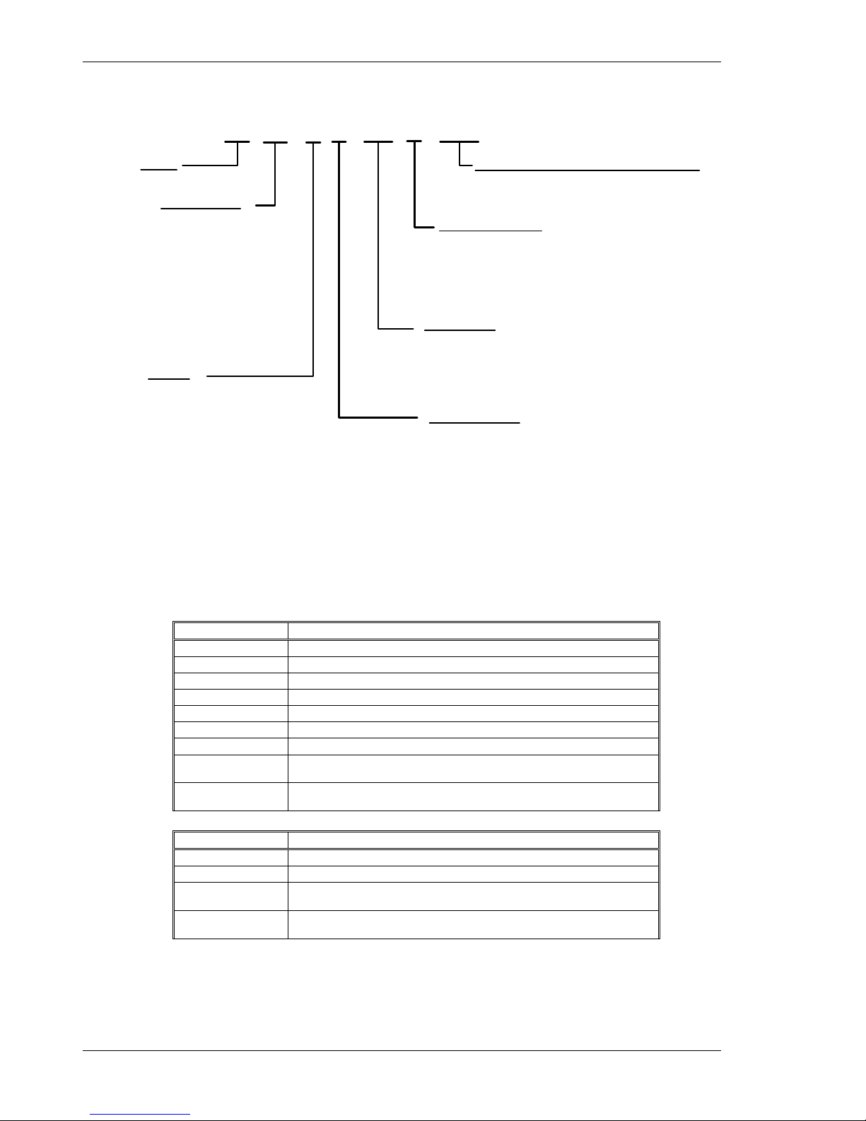
1.2 Model Number
S2 03 3 0 - VT S - 002
Family
S2 - 200 Servo Family
Current Rating
02 - 1.5 ARMS continuous,
4.5 ARMS peak
03 - 3 ARMS continuous,
9 ARMS peak
06 - 6 ARMS continuous,
18 ARMS peak
12 - 12 ARMS continuous,
30 ARMS peak
24 - 24 ARMS continuous,
48 ARMS peak
Voltage
3 - 20 - 90 VDC (03, 06 Current)
5 - 120 VAC doubler/240 VAC 1 ph
(02, 03 Currents Only)
6 - 120/240 VAC (All Currents)
Electrical Option
0 - No Electrical Option
Functionality
VT - Velocity/Torque modes
SD - SynqNet option card w/ micro-D connectors
SR - SynqNet option card w/ standard RJ connectors
CN - Position Node w/ CANOpen Interface
Feedback Support
S - SFD/Halls - All Units
SFD/Comcoder - CAN Option card
Sine encoder - SynqNet Option Card
EnDat 2.1 - SynqNet Option Card
Customization - omit for standard drives
000 - 019 Reserved for factory use
020 - 999 Reserved for customers
1.3 Drive Model Numbers and Descriptions
Here is a list of the various S200 Series Drives.
VTS – Analog Velocity/Torque Base Drive
SDS – SynqNet option card with Micro-D connectors
SRS – SynqNet option card with RJ-45 connectors
CNS – CAN/Indexer option card (Not documented in this manual)
AC Drive Description
S20260-VTS S200 120/240 VAC, 1/3-phase, 1.5/4.5 ARMS Base Unit
S20360-VTS S200 120/240 VAC, 1/3-phase, 3/9 ARMS Base Unit
S20250-VTS S200 120 VAC, doubler/240 VAC 1 ph 1.5/4.5 ARMS Base Unit
S20350-VTS S200 120 VAC, doubler/240 VAC 1 ph 3.9 ARMS Base Unit
S20660-VTS S200 120/240 VAC, 1/3-phase, 6/18 ARMS Base Unit
S21260-VTS S200 240 VAC, 1/3-phase, 12/30 ARMS Base Unit
S22460-VTS S200 240 VAC, 3-phase, 24/48 ARMS Base Unit
S2xxx0-SRS One of the above drives with optional SynqNet with RJ-45
connectors
S2xxx0-SDS One of the above drives with optional SynqNet with Micro-D
connectors
DC Drive Description
S20330-VTS S200 90 VDC, 3/9 ARMS Base Unit
S20630-VTS S200 90 VDC, 6/18 ARMS Base Unit
S2xx30-SRS One of the above drives with optional SynqNet with RJ-45
connectors
S2xx30-SDS One of the above drives with optional SynqNet with Micro-D
connectors

Danaher Motion 05/2008 Before You Begin
S200-VTS Product Manual 9
2 BEFORE YOU BEGIN
2.1 Safety
WARNING
READ these instructions before connecting power. Damage can
result from MISWIRING at the power terminals.
DANGEROUS voltages are present on power input and motor output
terminals.
Only qualified personnel are permitted to transport, assemble, commission, and maintain this
equipment. Properly qualified personnel are persons who are familiar with the transport,
assembly, installation, commissioning and operation of motors, and who have the appropriate
qualifications for their jobs.
Read all available documentation before assembling and using. Incorrect handling of products
described in this manual can result in injury and damage to people and/or machinery. Strictly
adhere to the technical information regarding installation requirements.
Keep all covers and cabinet doors shut during operation.
Be aware that during operation, the product has electrically charged components and hot
surfaces. Control and power cables can carry a high voltage, even when the motor is not
rotating.
Never disconnect or connect the product while the power source is energized.
After removing the power source from the equipment, wait at least 5 minutes before
touching or disconnecting sections of the equipment that normally carry electrical charges
(e.g., capacitors, contacts, screw connections). To be safe, measure the electrical contact
points to each other and to electrical safety earth with a meter before touching the
equipment.
2.2 Unpacking and Inspecting
Open the box and remove all the contents. Check to ensure there is no visible damage to any
of the equipment.
CAUTION
Use proper procedures when handling electronic
components to avoid damage to equipment.
CAUTION
Remove all packing material and equipment from the
shipping container. Be aware that some connector kits and
other equipment pieces may be quite small and can be
accidentally discarded. Do not dispose of shipping materials
until the packing list has been checked.
NOTE
Upon receipt of the equipment, inspect components to
ensure that no damage has occurred in shipment. If damage
is detected, notify the carrier immediately. Check all shipping
material for connector kits, documentation, diskettes, CDROM, or other small pieces of equipment.

Specifications 05/2008 Danaher Motion
10 S200-VTS Product Manual
3 SPECIFICATIONS
NOTE
Unless otherwise specified, the specifications are worse-case
limits and apply over the specified operating ambient
temperature and over the specified operating line voltage.
3.1 Drive Family Power
240 VAC Input 20-90 Vdc Input
S20260 S20360 S20660 S21260 S22460 S20330 S20630
Peak Output Current (RMS)1
(0 to 50°C) Amb (A
RMS
) 4.5 9.0 18.0 30.0 48 9.0 18.0
Minimum Peak Current Time
Start from 0 A
RMS
(sec) 3.0
Continuous Output Current Convection2
0 to 30° C amb (A
RMS
) 2.3 4.5 9.0 15.0 30.0 4.5 7.5
40° C amb (A
RMS
) 1.5 3.0 6.0 12.0 24.0 3.0 6.0
50° C amb (A
RMS
) 1.0 2.0 4.0 8.0 16.0 2.3 4.5
Peak Output Power (1 sec)
240 Vac (VA) 3 Phase 1500 3000 6000 10000 16000 - -
240 Vac (VA) 1 Phase 1400 2600 5000 8000 - - -
120 Vac (VA) 1 Phase 700 1300 2500 - - - -
75 Vdc (VA) - - - - - 750 1500
Drive Continuous Output Power
240 Vac 3 Phase (W) 600 1100 2000 4000 8000 - -
240 Vac 1 Phase (W) 500 900 1500 2500 3000 - -
120 Vac 1 Phase (W) 2506 4506 750 - - - -
75 Vdc (W) - - - - - 250 500
Continuous Motor Shaft Power @3000 RPM (Nominal Bus –10% 3 Phase/DC)
0 to 30° C amb (W) 3-ph 300 750 1500 2500 5000 180 315
0 to 30° C amb (W) 1-ph 300 750 1300 2200 2500 - -
40° C amb (W) 200 500 1000 2000 4000 125 250
RMS Line Current at Continuous Output Power
240 Vac 3Phase (A
RMS
) 2.7 5.0 9.0 16 24 - -
240 Vac 1 Phase (A
RMS
) 3.4 6.5 123 183 223 - -
120 Vac 1 Phase (A
RMS
) 3.4 6.5 123 - - - -
Maximum AC Line kVA (limits mains surges to drive)
AC Line kVA max 100 250 NA
+BUS Current With 75 VDC at Continuous Output Power
Average (ADC) NA 3.0 6.7
Inst. Peak (A
PeaK
) NA 12.7 25.5
Power Stage Diss. at
Icont, 40°C P
COnt
(W) 5
15 25 60 110 175 3 10
Shunt Regulator
Peak Power kW (500 mSec) 4 .4
@36Ω
6.4
@25Ω
10
@15Ω
10
@15Ω
15
@10Ω
Continuous Power (W) 440
@36Ω
640
@25Ω
1000
@15Ω
1500
@15Ω
2500
@10Ω
NA
Maximum Regen Duty
Cycle (%)
10
@36Ω
10
@25Ω
10
@15Ω
15
@15Ω
15
@10Ω
Regen Resistance (Ω)
25 – 50 25 – 50 12 – 50 8 – 50 8 – 50 NA

Danaher Motion 05/2008 Specifications
S200-VTS Product Manual 11
240 VAC Input 20-90 Vdc Input
S20260 S20360 S20660 S21260 S22460 S20330 S20630
Bus Capacitance Energy Absorption
340 VDC Nominal BUS 15.5 15.5 20 45 60 -
75 VDC BUS 4,000 µf
(75 to 80 VDC delta)
- - - - 1.5
Output Current Ripple Freq
f
S
(kHz)
20 20 16 16 16 31.2 31.2
Minimum Motor Inductance
l-l (mH)
5 2.5 1.5 0.9 0.6 - -
At 75 VDC - - - - - 0.4 0.2
Maximum Motor
Inductance l-l (mH)
300 150 75 45 30 30 15
Maximum Motor Power Cable Length4
18 AWG cable (m) 50 50 25 NA NA 50 25
14 AWG Cable (m) 50 50 NA 50 50
12 AWG Cable (m) 50
1
Peak Output Current listed is for sine mode. In six-step mode, the peak output
currents are scaled to give the same output torque as in sine mode with a pure
sinusoidal Back EMF motor.
To convert A
RMS
to A(0-pk), multiply A
RMS
* 1.414.
2
For intermediate ambient temperatures linearly derate between adjacent provided
0-30
o
C, 40o C, or 50o C ratings.
At higher ambient temperatures (above 30
o
C) the mounting surface temperature
must be thermally conductive enough to limit the mounting temperature to less
than 75o C.
3
Single phase operation of the S20660, S21260, S2460 requires derating of
continuous output power to avoid excessive ac line front end currents.
4
See Manual Appendix for voltage loss vs cable length.
5
Total drive dissipation = power stage dissipation + control power. Control power
adder is:
Base unit only = 7W
Base plus option card = 10W
6
For 120 Vac voltage doubled operation of S20250, S20350 units see Append i x D for
power specifications.

Specifications 05/2008 Danaher Motion
12 S200-VTS Product Manual
3.2 AC Input Drives - Control and Power
3.2.1 AC Control Power Supply
Input Voltage Range (RMS)
85 VAC to 265 VAC 1 phase 47 to 410 Hz
Or 120 VDC to 375 VDC
Ride Through Time for AC
Line Drop
85 VAC 60 Hz > 0.78 60 Hz cycles
120 VAC 60 Hz > 3.3 60 Hz cycles
240 VAC 60 Hz >18.5 60 Hz cycles
3.2.2 AC Motor Power Supply
Input Voltage Range (RMS)
S20260, S20360, S20660: 0 to 265 VAC
S21260, S22460: 120 to 265 VAC
Phases
1 or 3
Transformer Suggested KVA S20260: 1.5 to 2 kVA
S20360: 2.0 to 3 kVA
S20660: 3.0 to 5 kVA
S21260: 4.5 to 6 kVA
S22460: 8.0 to 12 kVA
Maximum AC Line KVA1 S20260, S20360, S20660: 100
S21260, S22460: 250
1
Maximum AC Line is specified to limit the mains surges to the drive.
3.2.3 AC Bus Voltage and Faults
240 VAC Input Nominal Bus
Voltage
320 VDC
120 VAC Input Nominal Bus
Voltage
155 VDC
BUS Undervoltage Fault
S20260, S20360, S20660 Default is None
S21260, S22460: 150 VDC
BUS Overvoltge (BusOV)
Fault
407 VDC + 5%
BUS Regen Voltage
= 0.974*BusOV = 397 VDC Nominal
3.2.4 AC Motor Power Inrush Current & Fusing
S20260 S20360 S20660
S21260,
S22460
Worse Case Inrush Peak
Current at 240 VAC
140 A 0-p 140 A 0-p 240 A 0-p
None, soft
start
Inrush pulse width
1.5 ms 1.5 ms 2.0 ms NA
Recommended
Fusing Line Inputs
S20260 S20360 S20660 S21260 S22460
Type – 250 VAC Time Delay Fuse
240 VAC 3 Phase
(ARMS)
Bussmann
FRN-R-5
Bussmann
FRN-R -8
Bussmann
FRN-R -15
Bussmann
JKS-20
Bussmann
JKS-30
240 VAC 1 Phase
(ARMS)
Bussmann
FRN-R -5
Bussmann
FRN-R -10
Bussmann
FRN-R -20
Bussmann
JKS-30
Bussmann
JKS-30
120 VAC 1 Phase
(ARMS)
Bussmann
FRN-R -5
Bussmann
FRN-R -10
Bussmann
FRN-R -20
NA NA

Danaher Motion 05/2008 Specifications
S200-VTS Product Manual 13
3.2.5 AC Control Power Inrush Current & Fusing
Worse Case Inrush Peak Current at 240 VAC
10 A 0-p
Inrush Pulse Width
1.60 ms
Fusing – Control Inputs
Bussmann MDA – 1/2
Nominal Power draw
Base: 7 W
With Option Card: 10 W
3.2.6 AC Power On Delay
Control Power Applied to Drive Operational
1.25 seconds
Bus Power To Full Bus On Soft Start Units
1.0 seconds
3.3 DC Input Drives - Control and Power
3.3.1 DC Control Power Supply
Control Voltage Range (VDC)
(J1-1 to J1-2)
+10 to +90
Control Input Power (watts)1
2 to 8
1
(20 watt min supply recommended) Refer to the DC Power Supply Section
for detailed application information and requirements.
3.3.2 DC Bus Voltage and Faults
+BUS Voltage Range (VDC) (J1-3 to J1-2)
+20 to +90
+BUS Undervoltage Fault
+17 VDC nominal
+BUS Overvoltage Fault
+91 VDC nominal
3.3.3 DC Control Power On Delay
Control Power Applied to Drive Operational
1.5 seconds
3.4 Motor Current Control
Motor Phase Current Waveform
(In Sine or six-step mode output torque = Motor
K
T
*Drive IFB)
Pure sinusoidal or six-step,
depending on feedback
device
Motor Shaft Torque (Ignoring motor magnetic saturation)
Peak (hot motor winding)
Multiply KT by 1.06 for cold motor winding (AKM
or PMA motors).
K
T
(N-m/ARMS)*Drive
Ipeak (ARMS)
Instantaneous
K
T
(N-m/ARMS)*IFB
(ARMS)

Specifications 05/2008 Danaher Motion
14 S200-VTS Product Manual
3.4.1 Current Loop Bandwidth
Maximum Bandwidth
AC Input Drive (kHz) 3
DC Input Drive (kHz) 5
Recommended Bandwidth
AC Input Drive (kHz) 2
DC Input Drive (kHz) 3
SFD Auto Set (kHz) AC & DC 2
Bandwidth Variation For Fixed Motor L
(% regulated independent of bus voltage)
± 2.5
Update Period (µs) 0.8
Recommended Max Motor Electrical Frequency (Hz)
AC Input Drive (Hz) 600
DC Input Drive (Hz) 900
3.4.2 Offset Current
Drive Typical Worst Case Over Temp
S20250, S20260
0.2% / 12 mA 0.5% / 32 mA
S20350, S20360
0.2% / 25 mA 0.5% / 64 mA
S20660
0.2% / 50 mA 0.5% / 128 mA
S21260
0.2% / 85 mA 0.5% / 210 mA
S22460
0.2% / 135 mA 0.5% / 340 mA
S20330
0.2% / 25 mA 0.5% / 64 mA
S20630
0.2% / 50 mA 0.5% / 128 mA
3.5 Velocity Loop
Maximum Stable Bandwidth (Hz with SFD)
800
Update Period (µs)
0.8
Range (rpm)
0 to 18,300
Command Resolution < 0.001 rpm analog
0.558 rpm serial
3.5.1 Velocity Loop Compensation
KVP Range (Depends on Ipeak) 0.00044 to 0.106 (Ipeak)
(1/rad/sec)
KVP Resolution (%)
5
KVI Range (Hz)
0 or 0, 0.0238 to 753.9
KVI Resolution (%)
5
ARF0 Range (Hz)
1.518 to 96382
ARF1 Range (Hz)
1.518 to 96382

Danaher Motion 05/2008 Specifications
S200-VTS Product Manual 15
3.6 Command I/O
3.6.1 Analog Command
Maximum Differential Range (volts)
±12.5
Maximum Single Ended Range (volts)
-12.5 to +16.0
Full Scale Tolerance (%)
Worse Case ±3.5
Typical ±1
Linearity (% Full Scale)
< 0.1
Monotonic to
< 2
-16
Full Scale
S/N Ratio Referred to Full Scale (bits
RMS
nominal)
3000 Hz A/D Bandwidth 14
800 Hz A/D Bandwidth 16
25 Hz A/D Bandwidth 18
Offset
Adjustable to 0
Maximum Unadjusted Offset (mV)
50
Offset Drift (µV/° C typ.)
250
CMRR
> 30 dB at 60 Hz
3.6.2 Analog Output (DacMon)
Resolution (bits)
14
Maximum Range (volts)
0.5 – 4.5
Full Scale Tolerance (%)
Worse Case ± 5
Typical ± 1
Linearity (% Full Scale)
<0.1
Monotonic to
< 2
-16
Full Scale
Offset (mV)
< 100
Offset Drift (µV/°C typ.)
250
3.6.3 HSINP – Step/PWM Command
HSINP - J4-10, J4-11
Input Voltage (volts)
3.0 – 6.0
Input Current (mA)
9.0 – 24.0
Minimum Pulse Width (ns)
250
HSINP as Step Command
Maximum Step Frequency (MHz)
1.5
HSINP as PWM Command
PWM Frequency (kHz)
0.25 to 250
Pulse Width
0 – 100% Duty Cycle
Pulse Width Distortion (ns)
250 maximum
3.6.4 MSINP - Direction Command
MSINP - J4-5, J4-1
Input Voltage (volts)
± (4.0 - 30.0)
Input Current (mA)
0.65 - 6.7
Direction Setup Time (µs)
100
Minimum Pulse Width (µs)
200

Specifications 05/2008 Danaher Motion
16 S200-VTS Product Manual
3.6.5 Quadrature Input
Quadrature Input CHA - J4-19, 20 CHB J4-21,22
Type
RS-422/RS-485
Input Voltage
Differential ± (0.2 to 12) volts
Common Mode –7 to +12
volts
Input Termination
None internal to the drive.
Maximum Line Frequency (kHz) 625 (corresponds to 2.5 MHz
quadrature pulse rate)
3.6.6 General Purpose Inputs
DINP1, DINP2, DINP3 – J4-2, 3, 4
Input Voltage (volts)
Referenced to DINPCOM (J4-5)
± (4.0 - 30.0)
Input Current (mA)
0.65 - 6.7
Response Time
1.0 ms
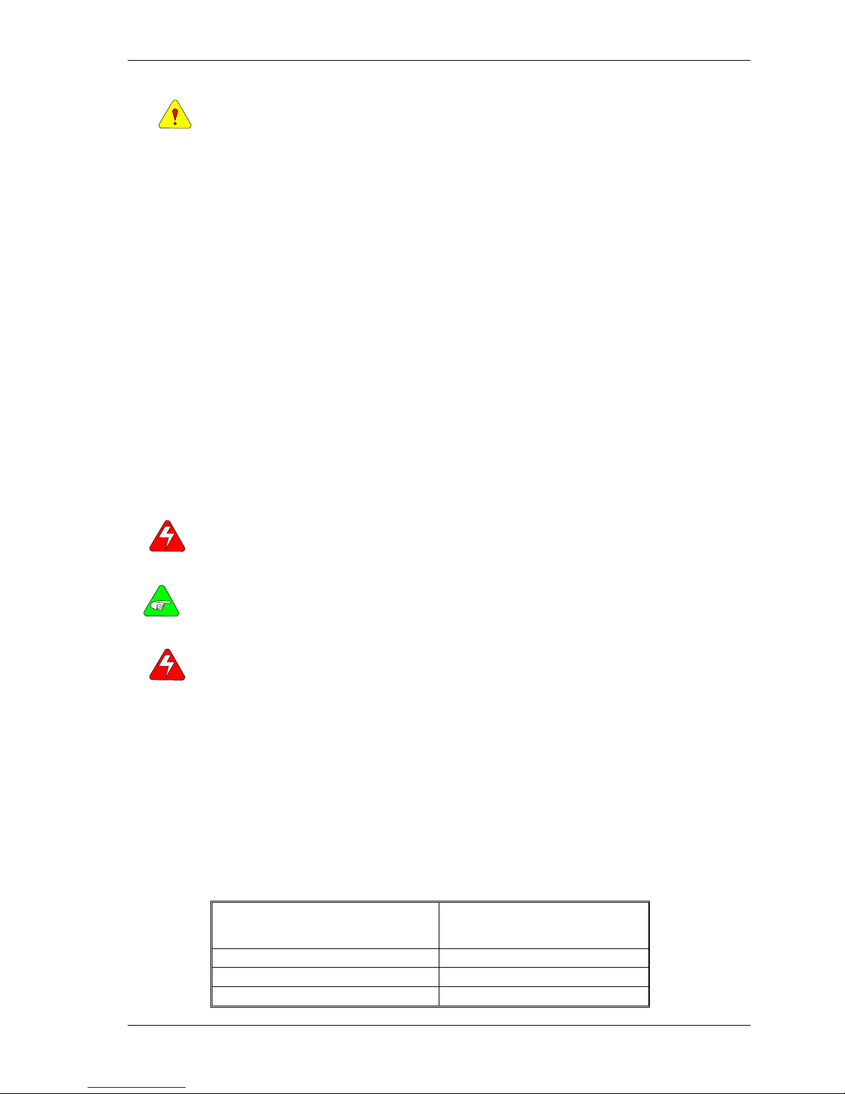
3.6.7 General Purpose Outputs
DOUT1, DOUT2 – J4-6,7 and J4-8,9
Maximum Output Voltage (volts)
- 0.30 to 30.0
Clamp Voltage (volts)
33 V ± 6%
Maximum Output Current
50 mA
On voltage (volts)
1.0 V at 10 mA
1.2 V at 50 mA
Response Time (ms)
1.0
3.6.8 Quadrature Outputs
Quadrature Output CHA- J4-19, 20 CH B- J4-21,22 CHZ- J4-17,18
Type
RS-422/RS-485
Output Voltage (volts)
5.0 V Differential Output Unloaded
Hysteresis
1/2 Quadrature Count
corresponding to 1/8
Encoder Line Count

Danaher Motion 05/2008 Specifications
S200-VTS Product Manual 17
3.7 Mechanical
S200 AC INPUT DRIVES S200 DC INPUT DRIVES
Base or w/ Option Card
Base Drive
w/ Option
Card
S20260
S20360
S20660 S21260
S22460
S20630-VT
S20330-VT
S20630-XX
S20330-XX
Drive Dimensions
Drive Height (A)
175 mm
6.90 in
177 mm
6.97 in
213 mm
8.39 in
152.4 mm
6.00 in
Drive Width (B)
54.8 mm
2.16 in
64.0 mm
2.52 in
76 mm
3.00 in
96.4 mm
3.80 in
28.7 mm
1.13 in
48.3 mm
1.90 in
Drive Depth1 (C)
131.6mm
5.18 in
152 mm
5.98 in
192 mm
7.57 in
100.8 mm
3.97 in
Mounting
Hardware
M4 or #8 M4 or #8
M4 or #8 M4 or #8
M4 or #8 M4 or #8
Drive Weight
0.77 kg
1.69 lb,
w/ option
0.84 kg
1.86 lb
0.82 kg
1.80 lb,
w/ option
0.89 kg
1.97 lb
1.33 kg
2.93 lb,
w/ option
1.40 kg
3.09 lb
2.56 kg
5.64 lb,
w/ option
2.63 kg
5.80 lb
0.40 kg
0.88 lb
0.50 kg
1.10 lb
1
Depth measurement is for drive only. Add approximately 50.8 mm (2 in) to
accommodate mating connectors and wire bend radius.
3.8 Environmental
Operating Temperature (°C) – Full Rating
0 to 40
Operating Temperature (°C) – Derated
Linearly Derate Continuous Current to
specified 50
o
C Rating
40 to 50
Pollution Degree
2
Storage Temperature (°C)
-35 to 85
Humidity (% non-condensing)
10 to 90
Altitude
<1500 m (5000 feet)
3.9 Smart Feedback Device (SFD)
3.9.1 Position Signal
Resolution/Rev (arc min)
24 bits = 0.0013
Repeatability (arc min RMS)
< ± 2
-19
Rev = ± 0.04
Noise
No Filtering (RMS) < 2
-17
Rev RMS = 0.16 arc-min
150 Hz Single Pole Filtered (RMS) < 2
-18
Rev RMS = 0.08 arc-min
10 Hz Single Pole Filtered (RMS) < 2
-19
Rev RMS = 0.02 arc-min
DC Offset Temperature Drift
< 2
-18
Rev/°C = 0.08 arc min/°C
Absolute Accuracy
AKM1 (arc min) ± 2
-10.3
Rev = ±17
AKM2 or 3, 4, 5, 6, 7 (arc min) ± 2
-11.1
Rev = ±10
Communications Update Period (µs)
51.2

Specifications 05/2008 Danaher Motion
18 S200-VTS Product Manual
3.9.2 Velocity Signal
Resolution (rpm)
< 0.001
Quanta (rpm)
0.07
Noise
No Filtering (rpm RMS) < 4
150 Hz Single Pole Filtered (rpm RMS) < 0.6
10 Hz Single Pole Filtered (rpm RMS) < 0.06
DC Accuracy
Typical at 25° C (%) ± 0.01
Worse case (%) ± 0.05
Ripple
AKM1 (% p-p at 1200 rpm) 2.5
AKM2, 3, 4, 5, 6, 7 (% p-p at 1200 rpm) 1.5
Offset (rpm)
< 0.0001
Communications Update Period (µs)
51.2
Hardware Interpolation Period (µs)
0.1
3.9.3 Emulated Encoder Output Signals
Available Resolutions (PPR)
Selectable By Rotary Switch S1
500, 512, 1000, 1024,
2000, 2048, 4096, 5000,
8192, 10000
Programmable Values See EncOutPPR
0 - 65535 integer
Maximum Output Line Frequency (MHz)
2.5
Max Recommended Speed at 32768 PPR (rpm)
2200
Max Recommended Speed at 16384 PPR (rpm)
4600
Max Recommended Speed at 4096 PPR (rpm)
18300
Marker Pulse Width
~ 2 Quadrature Pulses
3.9.4 General SFD Specifications
-3 dB Bandwidth (Hz)
> 2000
-45° Phase Lag (Hz)
> 1000
Max Tracking Rate (rpm)
> 48600
Max Recommended Rate (rpm)
25000
Max Tracking Acceleration (rpm/sec)
> 16x106
Maximum Feedback Cable Length
50 m (164 ft)

Danaher Motion 05/2008 Quick Start Guides
S200-VTS Product Manual 19
4 QUICK START GUIDES
There are two types of Quick Start Guides depending on the Communication Mode of the drive.
If you are not using an S200 Base Unit Drive (no SynqNet Option Card), follow the
S200 Base
Unit Drive Quick Start Guide.
If you are using an S200 SynqNet Drive, follow the
S200 SynqNet Drive Quick Start Guide.
4.1 S200 Base Unit Drive
This Quick Start Guide is designed to help a user quickly setup one of the following S200
Drives. See
Drive Model Numbers and Descriptions for a complete list of S200 drives.
S20330-VTS, S20630-VTS, S20260-VTS, S20360-VTS, S20250-VTS, S20350-VTS
The setup consists of the following steps:
• S200 Tools Software Installation
• Hardware Setup
• S200 Tools Communication Wizard
• Motor Feedback Configuration
• Save Options
4.1.1 S200 Tools Software Installation
Follow the installation instructions from the CD-ROM or zip file.
S200 Tools supports the following Operating Systems:
• Windows 2003 Server
• Windows XP, All Service Packs – (SP)
• Windows 2000, SP2
• Windows XP embedded
• Windows NT4, SP6

Quick Start Guides 05/2008 Danaher Motion
20 S200-VTS Product Manual
4.1.2 Hardware Setup
4.1.2.1 Drive Setup
Connect a serial communication cable between the drive and host computer to establish a
communication link between the host computer and the S200 Base Unit drive.
Plug one end of a serial communications cable to J5 (Serial Port) of the S200 drive and the
other end of the cable to the host computer's serial COM port.
NOTE: The serial communications cable is not shipped with the drive. It must be ordered
separately.
4.1.2.2 Motor Setup
If you are using an S200 Base Unit drive, use the J3 connector for motor feedback. Only SFD
motor feedback is supported on Base Unit drives. If you want to use SinCos or ComCoder as
motor feedback, you must use the AUX FB (J14) connector, which is not available on Base Unit
drives. See
Drive Model Numbers and Descriptions for a complete list of S200 drives.
4.1.3 S200 Tools Communications Wizard
4.1.3.1 Launch S200 Tools
Launch the S200 Tools program by clicking the desktop icon or from the Windows Start button
(Programs > Danaher Motion > S200Tools). The default location for S200Tools.exe, is
(C:\Program Files\Danaher Motion\S200Tools).
When the S200 Tools program is launched for the first time, no drives should be listed under
the Online or Offline Communications Mode.

Danaher Motion 05/2008 Quick Start Guides
S200-VTS Product Manual 21
4.1.3.2 Start Communication Wizard
Open the Communication Wizard by selecting it from the toolbar (Utilities > Communication
Wizard) or clicking the shortcut icon.
Select Serial as the Communications Mode and select the appropriate COM port.
If you do not know which type of drive is connected, click the Test button. The returned
message will either say that there is no connection, confirm that you have an S200 connected,
or tell you that the connected node is NOT an S200 drive.
Troubleshooting
If you receive the "No Connection" message, check the hardware connections.
After you have confirmed your setup, click the OK button.
The installed S200 drive(s) will now be listed as "Online" and will list its configuration and status
options.

Quick Start Guides 05/2008 Danaher Motion
22 S200-VTS Product Manual
4.1.4 Motor Feedback Configuration
The S200 Base Unit drives only support SFD motor feedback. If you are using SFD motor
feedback, no further configuration is needed. If you want to use SinCos or ComCoder as motor
feedback, you must use the AUX FB (J14) connector, which is not available on Base Unit
drives.
4.1.5 Save Options
There are three types of Save options. It is important to know how to use each type to ensure
that configurations are not lost.
Download NV – This button will save the parameter settings displayed in S200 Tools to the
selected drive. These parameters are saved to the drive's permanent memory and are recalled
during a power-up cycle.
Download Drive – This button will save the parameter settings displayed in S200 Tools to the
selected drive/node. However, unlike Download NV, these parameters are only saved to the
drive's temporary RAM and will not be recalled at a power-up cycle. It is recommended that you
use the Download Drive button when testing settings. Once you are satisfied with the settings,
click the Download NV button to permanently save the settings to the drive.
Save/Save As – You can also save the settings of a drive as a configuration file (*.S2C).
Remember, saving a configuration file does NOT save the settings to the drive. Configuration
files can be helpful for saving multiple drive setups. You can easily download a setting to a
drive by opening the configuration file in the Offline mode and clicking the Download NV/Drive
buttons once the proper drive is selected in the Online mode. It is recommended that you save
a configuration file for each setup.
4.2 S200 SynqNet Drive
Follow the instructions below if you are using one of the following S200 Series Drives:
S20250-SRS, S20260-SRS, S20350-SRS,
S20360-SRS, S20330-SRS, S20630-SRS,
S20250-SDS, S20260-SDS, S20350-SDS,
S20360-SDS, S20330-SDS, S20630-SDS
The setup consists of the following steps:
• MDK and SynqNet Controller Installation
• S200 Tools Software Installation
• Hardware Setup
• S200 Tools Communication Wizard
• SynqNet Configuration
• Motor Feedback Configuration
• Save Options
4.2.1 MDK and SynqNet Controller Installation
Before you can use an S200-SynqNet Drive, you must first install the Motion Developer's Kit
Software package and SynqNet controller from Motion Engineering Inc. For more information
about installation, please see
MEI's Technical Support website.
4.2.2 S200 Tools Software Installation
Follow the installation instructions from the CD-ROM or zip file. See S200 Tools Software
Installation Guide.
S200 Tools supports the following Operating Systems:
• Windows 2003 Server
• Windows XP, All Service Packs - (SP)
• Windows 2000, SP2
• Windows XP embedded
• Windows NT4, SP6

Danaher Motion 05/2008 Quick Start Guides
S200-VTS Product Manual 23
4.2.3 Hardware Setup
4.2.3.1 Drive Setup
NOTE: The drive serial port (J5) is disabled on SynqNet drives.
If you are using an S200 SynqNet Drive, you need to establish SynqNet communication link
between the S200 SynqNet Drive and the SynqNet motion controller.
Plug one end of an Ethernet communications cable to J11 (SynqNet IN) of the S200 drive and
the other end to the SynqNet controller's OUT port.
One Drive/Node
Use another Ethernet communications cable to connect J12 (SynqNet OUT) of the S200 drive
to the XMP-SynqNet controller's SynqNet IN port.
Multiple Drives/Nodes
Connect an Ethernet communications cable from the XMP-SynqNet controller's OUT port to the
SynqNet IN port (J11) of the first drive/node. Connect an Ethernet cable from the node's
SynqNet OUT port (J12) to the SynqNet IN port (J11) of the next node. Connect another cable
from the SynqNet OUT port (J12) of the last node in the topology to the SynqNet IN port of the
XMP-SynqNet controller.
NOTE: Although you can connect other SynqNet supported nodes/drives on the SynqNet
network, you will only be able to configure the S200 Series Drives with the S200 Tools
software. S200 Tools will only communicate with S200 Series Drives.

Quick Start Guides 05/2008 Danaher Motion
24 S200-VTS Product Manual
4.2.3.2 Motor Setup
Depending on the type of motor feedback that is used, you will need to use the appropriate
feedback connector.
Motor Feedback J3 Feedback J14 AUX FB
SFD X SinCos (with Endat 2.1/2.2) - X
SinCos (with Halls) - X
ComCoder (Incremental + Halls) - X
4.2.4 S200 Tools Communication Wizard
4.2.4.1 Launch S200 Tools
Launch the S200 Tools program by clicking the desktop icon or from the Windows Start button
(Programs > Danaher Motion > S200Tools). The default location for S200Tools.exe, is
(C:\Program Files\Danaher Motion\S200Tools).
When the S200 Tools program is launched for the first time, no drives should be listed under
the Online or Offline Communications Mode.

Danaher Motion 05/2008 Quick Start Guides
S200-VTS Product Manual 25
4.2.4.2 Start Communication Wizard
Open the Communication Wizard by selecting it from the toolbar (Utilities > Communication
Wizard) or clicking the shortcut icon.
Select SynqNet as the Communications Mode.
If you do not know which type of drive is connected, click the Test button. The returned
message will either say that there is no connection, confirm that you have an S200 connected,
or tell you that the connected node is NOT an S200 drive.
After you have confirmed your setup, click the OK button.
The installed S200 drive(s) will now be listed as "Online" and will list its configuration and status
options. If there are additional S200 nodes on the network, they are automatically discovered.
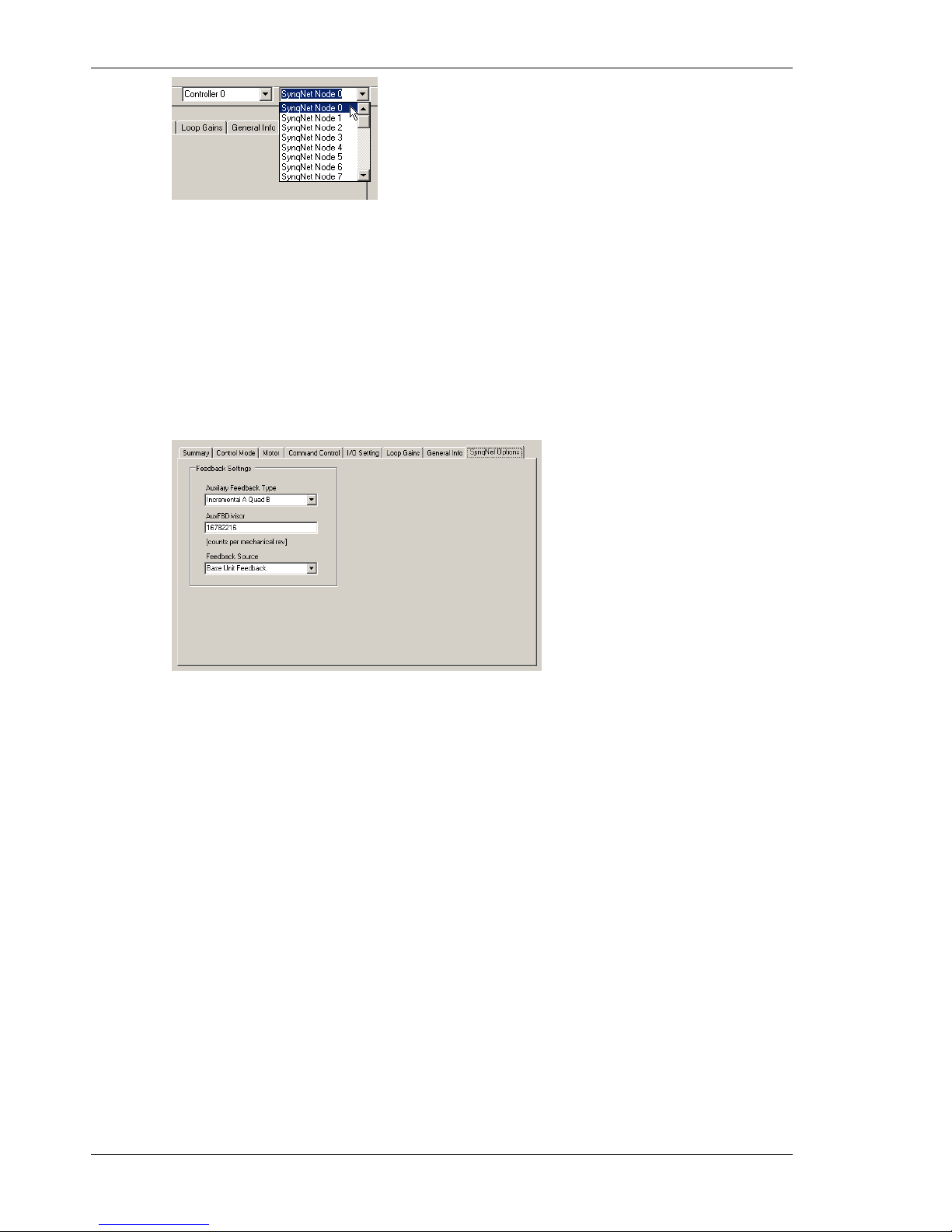
When using a network with multiple SynqNet nodes, use the SynqNet controller/node pulldown
bars to select a particular node on the network to display in the Online mode.
Quick Start Guides 05/2008 Danaher Motion
26 S200-VTS Product Manual
NOTE for SynqNet: Although the S200 Tools software maintains communication with all
properly connected S200 drives drives on the SynqNet network, only one SynqNet node will be
displayed at a time under the Online display.
4.2.5 SynqNet Configuration
The next step is to set the proper drive and motor feedback configurations.
Under the SynqNet Options tab, select the source for motor feedback (Feedback Source).
Select Base Unit Feedback if the motor feedback is connected to J3 on the S200 Drive.
Select Option Card Feedback if the motor feedback is connected to J14 on the S200 Drive.
4.2.6 Motor Feedback Configuration
The next step is to set the proper motor feedback configurations.
4.2.6.1 SFD
If you are using SFD motor feedback, no further configuration is needed.

Danaher Motion 05/2008 Quick Start Guides
S200-VTS Product Manual 27
4.2.6.2 SinCos or ComCoder
If you are using SinCos or ComCoder as motor feedback, use the equations below to
determine the appropriate parameters for setup.
Kip
Kip = 2*PI()*2000*(motor line to line inductance)
Ex: l-l inductance = 0.018 H
Kip = 2*PI()*2000*(0.018)
Kip = 226 V/A
I2TF0
I2TF0 = 5/(2*PI()*(motor time constant in minutes)*60))
Ex: Mtc = 20 minutes
I2TF0 = 5/(2*PI()*20*60)
I2TF0 = 0..000663 Hz
I2TTrip
I2TTrip = (motor continuious current)*1.25
Ex: Ics = 4 Arms
I2TTrip = 4*1.25
I2TTrip = 5 Arms
ILmtPlus
ILmtPlus = (motor peak current)/(drive peak current)*100
Ex: Motor Ip = 4.5 Arms, Drive Ip = 9 Arms
Motor Ip = (4.5/9)*100
Motor Ip = 50%
ILmtMinus
Typically ILmtMinus is set to the same value as ILmtMPlus. Although there can be asymetrical
current limits in the drive.
Dpoles
Dpoles = motor poles
4.2.7 Save Options
There are three types of Save options. It is important to know how to use each type to ensure
that configurations are not lost.
Download NV - This button will save the parameter settings displayed in S200 Tools to the
selected drive. These parameters are saved to the drive's permanent memory and are recalled
during a power-up cycle.
Download Drive - This button will save the parameter settings displayed in S200 Tools to the
selected drive/node. However, unlike Download NV, these parameters are only saved to the
drive's temporary RAM and will not be recalled at a power-up cycle. It is recommended that you
use the Download Drive button when testing settings. Once you are satisfied with the settings,
click the Download NV button to permanently save the settings to the drive.
Save/Save As - You can also save the settings of a drive as a configuration file (*.S2C).
Remember, saving a configuration file does NOT save the settings to the drive. Configuration
files can be helpful for saving multiple drive setups. You can easily download a setting to a
drive by opening the configuration file in the Offline mode and clicking the Download NV/Drive
buttons once the proper drive is selected in the Online mode. It is recommended that you save
a configuration file for each setup.

Mounting the Drive 05/2008 Danaher Motion
28 S200-VTS Product Manual
5 MOUNTING THE DRIVE
The S200 drives are designed for operation in a cabinet using the following installation
instructions:
Mount the drives vertically inside a cabinet on a flat, solid, electrically conductive mounting
surface that is connected to PE (Protective Earth Ground) and capable of supporting the weight
of the unit.
Provide a good connection to PE. Remove the paint on the mounting surface over an area
extending at least 12 mm (0.5 in) from the mounting bolts to achieve good electrical connection
over a large area between the drive and grounded mounting surface.
Ensure that the environment within the cabinet meets the requirements listed in the
Specifications.
5.1 Mounting Dimensions
AC INPUT DRIVES DC INPUT DRIVES
AC1
AC2
AC3 AC4 AC5
DC Base
Drive
w/
Option
S20260
S20360
S20660 S21260 S22448
S20330VTS
S20630VTS
S20330x
S20630x
Drive Dimensions
Drive Height (A)
175.0 mm
6.90 in
177 mm
6.97 in
213 mm
8.39 in
152.4 mm
6.00 in
Drive Width (B)
54.8 mm
2.16 in
64.0 mm
2.52 in
76 mm
3.00 in
96.4 mm
3.80 in
28.7 mm
1.13 in
48.3 mm
1.90 in
Drive Depth1 (C)
131.6 mm
5.18 in
152 mm
5.98 in
192 mm
7.57 in
100.8 mm
3.97 in
Clearance Requirements
Top and Bottom
(D)
12.7 mm
0.50 in
12.7 mm
0.50 in
12.7 mm
0.50 in
19 mm
0.75 in
12.7 mm
0.50 in
12.7 mm
0.50 in
Side to Side (E)
12.7 mm
0.50 in
12.7 mm
0.50 in
12.7 mm
0.50 in
19 mm
0.75 in
12.7 mm
0.50 in
12.7 mm
0.50 in
Mounting Dimensions
Horizontal
Mounting Offset
(F)
25.6 mm
1.01 in
25.6 mm
1.01 in
31.7 mm
1.25 in
57.5 mm
& 6.5
mm
24.6 mm
0.97 in
24.6 mm
0.97 in
Vertical Mounting
Offset (G)
4.3 mm
0.17 in
4.3 mm
0.17 in
2.1 mm
0.08 in
5.0 mm
0.20 in
4.1 mm
0.16 in
4.1 mm
0.16 in
Vertical Mounting
Height (H)
166.4
mm
6.55 in
166.4
mm 6.55
in
169.5
mm 6.67
in
202.5
mm 7.97
in
144.3
mm
5.68 in
144.3
mm
5.68 in
Drive to Drive
Mounting (J)
67.5 mm
2.66 in
76.7 mm
3.02 in
88.7 mm
3.39 in
115.4
mm 4.54
in
41.40
mm
1.63 in
60.96
mm
2.40 in
Mounting
Hardware
M4 or #8 M4 or #8 M4 or #8 M4 or #8 M4 or #8 M4 or #8
Drive Weight
(no option card)
0.77 kg
1.69 lb
0.85 kg
1.86 lb
1.33 kg
2.93 lb
2.56 kg
5.64 lb
0.40 kg
0.88 lb
0.5 kg
1.10 lb
1
Depth measurement is for drive only. Add approximately 50.8 mm (2 in) to depth
given in the table to accommodate mating connectors and wire bend radius.
Danaher Motion 05/2008 Mounting the Drive
S200-VTS Product Manual 29
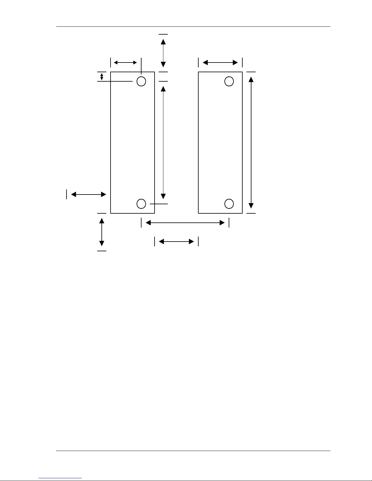
Side Clearance
(E)
Bottom
Clearance
(D)
Horizontial
Mounting Offset
(F)
Vertical
Mounting
Offset
(G)
Drive to Drive Mounting
(J)
Drive
Height
(A)
Drive Width
(B)
Vertical
Mounting
Height
(H)
For Drive
Mounting
use M4 or #8
Hardware
For Drive
Mounting
use M4 or #8
Hardware
Top Clearance
(D)
Side Clearance
(E)
Mounting Dimensions - Front View
See the preceding table for mounting dimensions.
Mounting the Drive 05/2008 Danaher Motion
30 S200-VTS Product Manual
5.2 Mechanical Outline Drawings
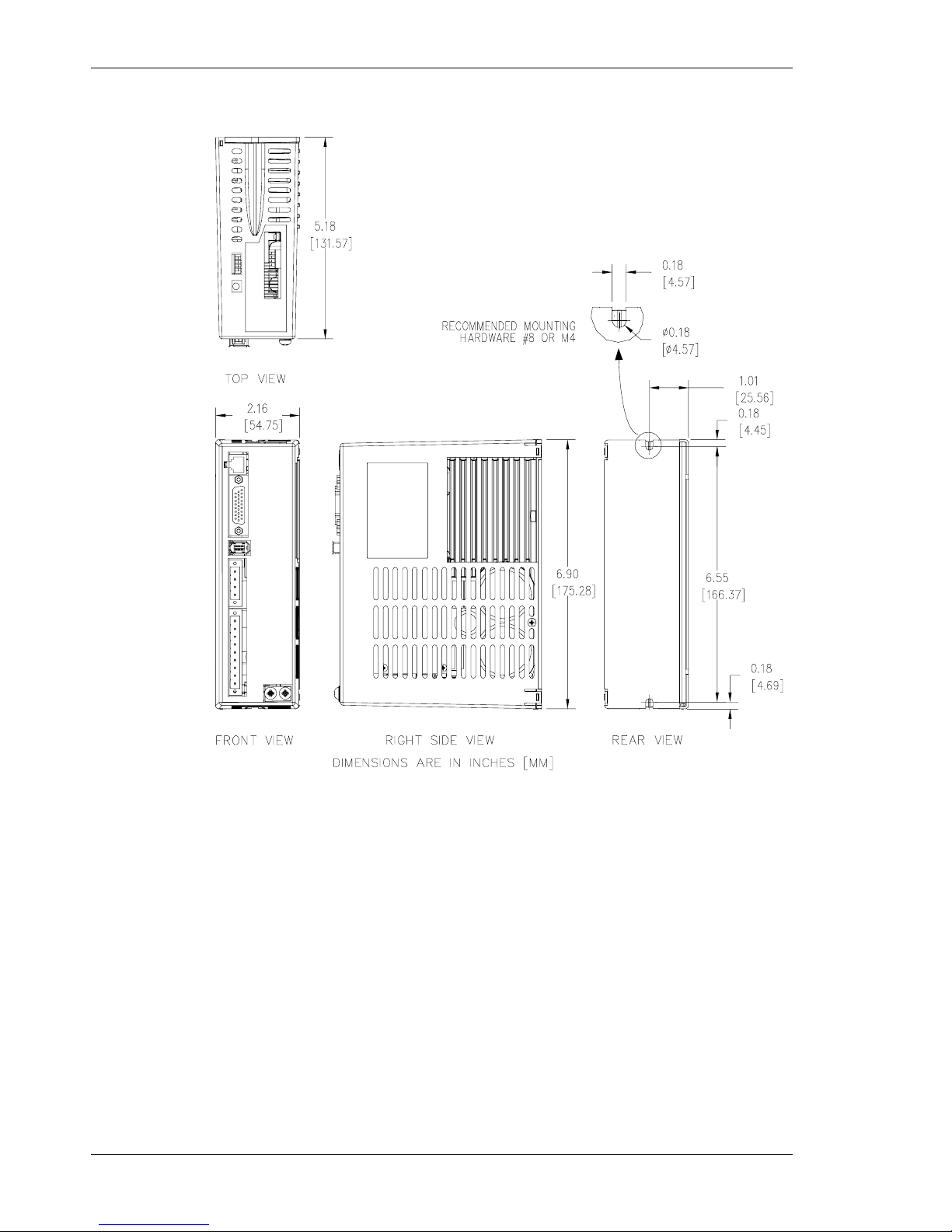
5.2.1 Base AC Drive (S20260-, S20360-, S20660-VTS)
Note: All S20660-VTS dimensions are exactly as shown above except for the product width.
The 2.16 in [54.75 mm] width above changes to 2.52 in [64.0 mm] for the S20660-VTS.
Enclosure and mounting dimensions for Option card equipped units are the same.

Danaher Motion 05/2008 Mounting the Drive
S200-VTS Product Manual 31
5.2.2 Base AC Drive (S21260-VTS)
76.1 [3.00]
150.5 [5.93]
178.8 [7.04]
4.6 [0.18]
169.5 [6.67]
4.8 [0.19]
31.7 [1.25]
4.6 [0.18] 2 Places
Ø4.6 [Ø0.181] 2 Places
DETAIL A
SCALE 1 : 1
Dimensions are mm [inches]
FRONT VIEW RIGHT SIDE VIEW REAR VIEW
TOP VIEW
Note: Enclosure and mounting dimensions for Option card equipped units are the same.

Mounting the Drive 05/2008 Danaher Motion
32 S200-VTS Product Manual
5.2.3 Base AC Drive (S22460-VTS)
Note: Enclosure and mounting dimensions for Option card equipped units are the same.

Danaher Motion 05/2008 Mounting the Drive
S200-VTS Product Manual 33
5.2.4 Base DC Drive (S20330-, S20630-VTS)
Note: Enclosure and mounting dimensions for Option card equipped units are NOT the same.
See Section 5.2.6 for details.

Mounting the Drive 05/2008 Danaher Motion
34 S200-VTS Product Manual
5.2.5 SynqNet AC Drive (S20260-, S20360-, S20660-SRS)
6.55
166.37[]
1.01
25.56[]
2.16
54.75[]
5.18
131.57[]
6.89
175.01[]
0.17
4.32[]
0.17
4.32[]
0.18
4.57[]
Ø
0.18
4.57[]
TOP VI EW
FRONT VI EW
RI G H T SI D E V I E W
REA R V I EW
RECO M M END E D M O U N T I N G
HARDWARE: #8 or M4
DIMENSIONS ARE IN INCHES [ MM]
Note: All S20660-SRS, S20660-SDS dimensions are exactly as shown above except for the
product width. The 2.16 in [54.75 mm] width above changes to 2.52 in [64.0 mm] for the
S20660-SRS, S20660-SDS.

Danaher Motion 05/2008 Mounting the Drive
S200-VTS Product Manual 35
5.2.6 SynqNet DC Drive (S20330-, S20630-SRS)
FRONT VI EW
RI G H T SI D E V I EW
REA R VI E W
DIMENSIONS ARE IN INCHES [MM]
TOP VI EW
Ø
3.97
100.84[]
1.90
48.26[]
0.18
4.57[]
0.18
4.57[]
RECOMMENDED MOUNTING
H A RD W A RE: #8 o r M 4
0.97
24.64[]
0.16
4.06[]
5.68
144.27 ]
[
0.16
4.06 ]
[
6.00
152.40 ]
[

Wiring the Drive 05/2008 Danaher Motion
36 S200-VTS Product Manual
6 WIRING THE DRIVE
WARNING
READ these instructions before connecting power. Damage can
result from MISWIRING at the power terminals.
DANGEROUS voltages are present on power input and motor output
terminals.
6.1 AC Input Drive Wiring
6.1.1 AC Drive (S20260-, S20360-, S20660-VTS)
S200
AC
INPUT
DRIVE
1
2
SFD OR
HALLS
1
2
3
4
J1
FEEDBACK
6
5
4
3
MOTOR
AC
POWER
SFD +5 RTN
SFD +5V
SFD COM+/CU
NC/CV
NC/CW
J3
1
2
3
4
J2
MOTOR
POWER
-BUS
REGEN
5
6
7
SFD COM-
8
9
+BUS
36 Ohm
Optional
External
Regen Resistor
COMMAND I/O
J4
DINP1 (ENABLE)
2
1
DINP COM
DINP2 (INHIBIT+)
3
DINP3 (INHIBIT-)
4
MSINP1 (DIRECTION)
5
DOUT1-
6
DOUT1+ (FAULT)
7
DOUT2-
8
DOUT2+ (RUN)
9
HSINP1+ (STEP/PWM)
10
HSINP1-
11
SFD BAT+
12
I/O RTN
13
DAC MON114DAC MON2
15
I/O RTN
16
CH Z OUT17CH Z OUT
1819202122
I/O RTN
23
ANA CMD+
24
ANA CMD-
25
I/O RTN
26
SERIAL
PORT
J5
RX232
2
1
NC
I/O RTN3I/O RTN
4
TX232
5NC6
C1 CTRL VAC
C2 CTRL VAC
47 - 63 Hz
240/120 VAC
PE
L1 240/120 VAC NEUTRAL
47 - 63 Hz
240/120 VAC
L2 240/120 VAC HOT
L3 240 VAC
PHASE U
PHASE V
PHASE W
PE
CH A OUT / CH A IN
CH A OUT / CH A IN
CH B OUT / CH B IN
CH B OUT / CH B IN
Notes:
1. For S2xx50 voltager doubler models see
Appendix for ac line interface details.
2. The motor and feedback cable shielding
shown is for individual cables. Kollmorgen
also offers a combined motor and feedback
cable.

Danaher Motion 05/2008 Wiring the Drive
S200-VTS Product Manual 37
6.1.2 AC Drive (S21260-, S22460-VTS)
Wiring the Drive 05/2008 Danaher Motion
38 S200-VTS Product Manual
6.2 J1 – AC Input Drive Power
The S200 AC input drives are capable of direct line operation. All units are fully isolated and do
not require external isolation transformers. The inrush current on the connection to the line is
internally limited to a safe level for the drive. There are no voltage selection or ranging switches
required to operate within the specified voltage input ranges.
The S200 series drives are functionally compatible with all standard forms of three phase AC
lines:
Grounded neutral WYE
Open-Delta Grounded Leg
TEE
NOTE
The customer is responsible for supplying the appropriate fuses or
circuit breakers in the J1 AC motor power lines to comply with local
electrical codes.
The control input power required is between 5 and 10 watts. The AC input motor power
depends on output power and losses in the power stage.
CAUTION
Appendix G – Regulatory Information of this manual contains
additional information needed to ensure regulatory compliance.
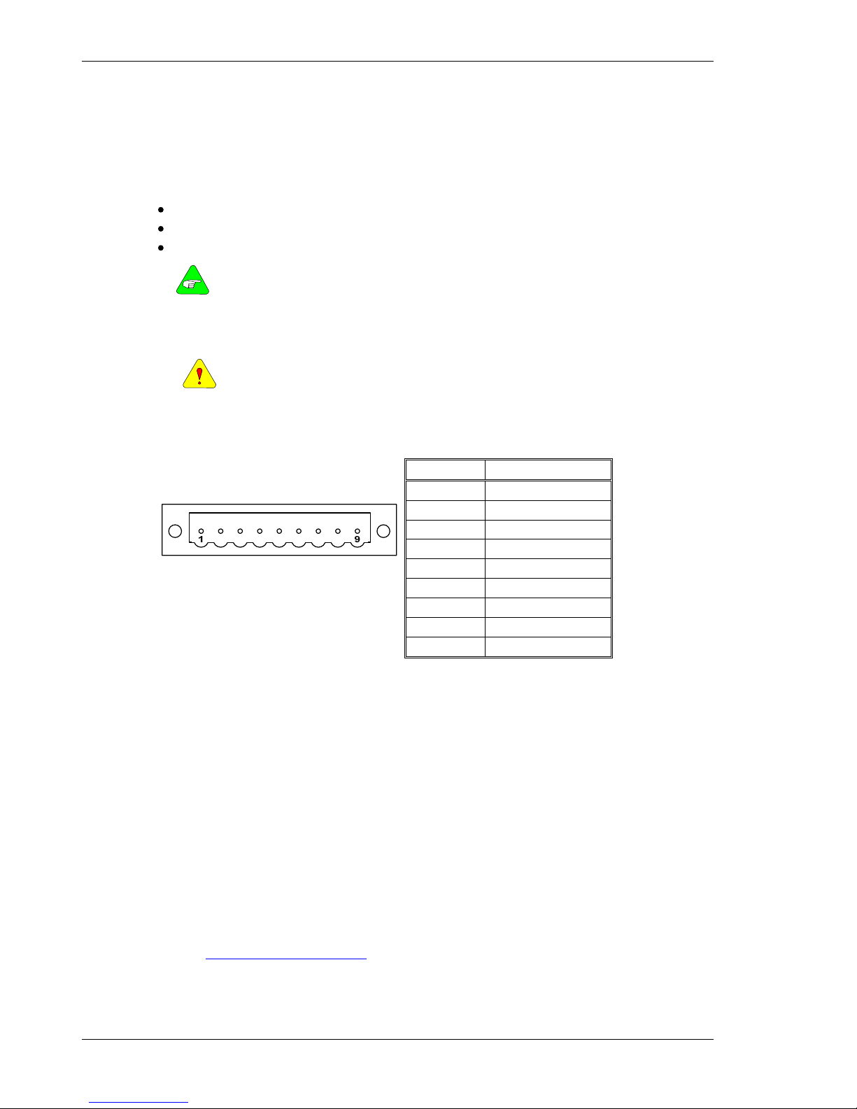
On AC input drives with peak current < 18 Arms, J1 is a 9 pin pluggable connector (shown
below). On larger AC input drives connections are to fixed terminal block TB1 that needs no
mating connector. See wiring diagrams for full connection details.
Pin Description
J1-1 PE (Protective Earth)
J1-2 REGEN
J1-3 -BUS
J1-4 +BUS
J1-5 C2 CTRL VAC
J1-6 C1 CTRL VAC
J1-7 L3 240 VAC
J1-8 L2 240/120 VAC
J1 Connector view from front of drive.
J1-9 L1 240/120 VAC
Mating Connector Information for S20260, S20250, S20360, S20560, S20660
Screw Terminal Connector
12 – 24 AWG Wire Range, Phoenix MSTB2,5/9-STF-5,08-BK
OR
Spring Cage Clamp Connector
12 – 24 AWG Wire Range, Phoenix FKC 2,5/9-SFT-5,08-BK
OR
Crimp Connector
Crimp Shell
14-20 AWG Wire Range, Phoenix MSTBC 2,5/9-STZF-5,08-BK
Crimp Contact
14-16 AWG Wire Range, Phoenix MSTBC-MT 1,5-2,5
Crimp Contact
18-20 AWG Wire Range, Phoenix MSTBC-MT 0,5-1,0
Refer to
http://www.phoenixcon.com.
Danaher Motion 05/2008 Wiring the Drive
S200-VTS Product Manual 39
CAUTION
To avoid damage to the connector and drive, NEVER plug or unplug J1 with
power applied.
J1-1 or Chassis
Screw PE
Protective Earth
This chassis ground point must be connected to
Protective Earth ground. The connection at the
Protective Earth ground end must be hard wired
(do not use a pluggable connection). A ground
fault detector (RCD) cannot be depended on for
safety.
J1-2 or TB1-5
REGEN
Connection for an optional regeneration power
resistor to absorb regenerated energy from the
motor. Models S20260 and S20360 typically use
36 Ω. S20660, S21260 typically use 12.5 Ω, and
S22460 typically uses 8 Ω. Other values within
the min to max resistance specification range can
be used. Use a Wire wound resistor with 1500
V
RMS
isolation between terminals and case. Many
applications do not require a regen resistor. If
over-voltage faults occur during motor
deceleration, then the more kinetic energy is being
returned to the bus capacitors than they can
handle. Connect the proper Ohmage 50 to 1000
watt power resistor from this terminal, to terminal
J1-4 (+BUS) in order to eliminate the over-voltage
faults. The power rating of the regen resistor
depends on the amount of regenerated energy
that needs to be dissipated.
WARNING
The regen input is not short circuit protected. The regen resistance MUST
be within specified ranges to prevent damage to the drive. For example,
S20260, S20360 drives must be between 25 to 50 Ω.
NOTE
For safety, either mount the external resistor on a grounded panel or wire it
to a grounded connection. The terminals of the resistor MUST NOT be
grounded.
WARNING
Wait 5 minutes after power is removed for the bus cap voltage to decay to a
safe level before touching the regen resistor or wiring. Monitor the voltage
on the bus caps with a voltmeter from +BUS (J1-4) to -BUS (J1-3).
J1-3 or TB1-6
-BUS
The -BUS terminal is usually left open during
normal operation. In special multi-axis
applications, drive buses can be wired in parallel
to allow returned energy from one motor to power
another and limit high regen powers.
J1-4 or TB1-7
+BUS
The +BUS terminal is used with the J1-2, REGEN,
terminal to add a regen resistor to the drive to
absorb regenerated energy.
J1-5, J1-6
or J1-2, J1-3
C2 CTRL VAC
C1 CTRL VAC
These terminals connect 120/240 VAC power to
the drive’s control voltage power supply.
S21260, S2460 on separate 3 pin pluggable J1.
These terminals are NOT connected to the bus
power L1, L2 (J1-8,9) inside the drive.
Input Voltage Range (RMS) 85 VAC to 265 VAC single phase
47 to 63 Hz
120 VDC to 375 VDC
Inrush Peak Current
10 A 0-p with 240 VAC Input
Inrush pulse width
1.60 ms
Fusing
Bussmann MDA – ½

Wiring the Drive 05/2008 Danaher Motion
40 S200-VTS Product Manual
NOTE
For maximum ride through capability a 240 VAC input is recommended.
J1-7, J1-8, J1-9
or TB1-8,9,10
L3 240 VAC
L2 240/120 VAC
L1 240/120 VAC
These terminals connect 120/240 VAC power to
the drive’s output power stage BUS for motor
power.
For single-phase operation, 120/240 use inputs
J1-8, L2, and J1-9, L1.
Input Voltage Range (RMS)
S20260, S20360, S20660: 0 to 265 VAC
S21260, S22460: 120 to 265 VAC
Phases
1 or 3
Transformer
(recommended KVA if
transformer is required.)
S20260: 1.5 to 2 kVA
S20360: 2.0 to 3 kVA
S20660: 3.0 to 5 kVA
S21260: 4.5 to 6 kVA
S22460: 8.0 to 12 kVA
Maximum AC Line KVA1
S20260, S20360, S20660: 100
S21260, S22460: 250
1
Maximum AC Line is specified to limit the mains surges to the drive.
Recommended Fusing
Line Inputs
S20260 S20360 S20660 S21260 S22460
Type – 250 VAC Time Delay Fuse
240 VAC 3 Phase
(ARMS)
Bussmann
FRN-R-5
Bussmann
FRN-R-8
Bussmann
FRN-R-15
Bussmann
JKS-20
Bussmann
JKS-30
240 VAC 1 Phase
(ARMS)
Bussmann
FRN-R -5
Bussmann
FRN-R-10
Bussmann
FRN-R-20
Bussmann
JKS-30
Bussmann
JKS-30
120 VAC 1 Phase
(ARMS)
Bussmann
FRN-R -5
Bussmann
FRN-R-10
Bussmann
FRN-R-20
NA NA

Danaher Motion 05/2008 Wiring the Drive
S200-VTS Product Manual 41
6.3 DC Input Drive Wiring
S200
DC
INPUT
DRIVE
1
2
SFD OR
HALLS
1
2
3
4
FEEDBACK
6
5
4
3
MOTOR
SFD +5 RTN
SFD +5V
SFD COM+/CU
NC/CV
NC/CW
J3
J2
MOTOR
POWER
SFD COM-
NOTE:
I/O RTN and BUS/CTRL GND pins are
connected together in the drive
+BUS
J1
DC
POWER
1
2
3
BUS/CTRL GND
+CTRL
CHASSIS/PE
COMMAND I/O
J4
DINP1 (ENABLE)
2
1
DINP COM
DINP2 (INHIBIT+)
3
DINP3 (INHIBIT-)
4
MSINP1 (DIRECTION)
5
DOUT1-
6
DOUT1+ (FAULT)
7
DOUT2-
8
DOUT2+ (RUN)
9
HSINP1+ (STEP/ PWM)
10
HSINP1-
11
SFD BAT+
12
I/O RTN
13
DAC MON114DAC MON2
15
I/O RTN
16
CH Z OUT17CH Z OUT
1819202122
I/O RTN
23
ANA CMD+
24
ANA CMD-
25
I/O RTN
26
SERIAL
PORT
J5
RX232
2
1
NC
I/O RTN3I/O RTN
4
TX232
5NC6
PHASE U
PHASE V
PHASE W
GND
CH A OUT / CH A IN
CH A OUT / CH A IN
CH B OUT / CH B IN
CH B OUT / CH B IN
- Main Power
+ 20 - 90 VDC
+BUS
TB1
DC
POWER
1
2
3
BUS/CTRL GND
+CTRL
Alternate Dual Supply Wiring
-
Control Power
+ 10 - 90 VDC
- Main Power
+ 20 - 90 VDC

Wiring the Drive 05/2008 Danaher Motion
42 S200-VTS Product Manual
6.4 J1 – DC Input Drive Power
The S200 DC input drives should be powered from power supplies with reinforced isolation.
On DC input drives, J1 is a 3 pin pluggable connector.
1
3
(J1 Connector view from
front of drive).
Pin Description
J1-1 +CTRL
J1-2 BUS/CTRL GND
J1-3 +BUS
CAUTION
To avoid damage to the connector and drive, NEVER plug or unplug J1 with power
applied.
Mating Connector Information
Screw Terminal Connector
12 – 24 AWG Wire Range, Phoenix MSTB2,5/3-STF-5,08-BK
OR
Spring Cage Clamp Connector
12 – 24 AWG Wire Range, Phoenix FKC 2,5/3-SFT-5,08-BK
OR
Crimp Connector
Crimp Shell
14-20 AWG Wire Range, Phoenix MSTBC 2,5/3-STZF-5,08-BK
Crimp Contact
14-16 AWG Wire Range, Phoenix MSTBC-MT 1,5-2,5
Crimp Contact
18-20 AWG Wire Range, Phoenix MSTBC-MT 0,5-1,0
Refer to www.phoenixcon.com.
J1-1
+CTRL
Control power input. The DC drive accepts +10 to +90 VDC on this
input referenced to J1-2. An isolated regulated or isolated unregulated
power supply can be used. This input can be connected to +Bus input
(J1-3) and powered by the same supply as +Bus. The control power
supply should be rated for 20 watts. While the power drain typically is 2
W to 8 W, a 20 W supply ensures reliable starting of the drive.
J1-2
BUS/CTRL GND
Power return for the control and BUS power supplies. The
BUS/CTRL GND is connected to I/O RTN internally in the drive.
J1-3
+BUS
Main power input to the drive. The DC drive accepts +20 to +90 VDC
on this input referenced to J1-2. An isolated regulated or isolated
unregulated power supply can be used. The +Bus power drain with +Bus
voltage at 75 VDC is in the range shown below. It varies according to the
application and motor.
S20330 (3 Amp) S20630 (6 AMP)
+Bus (Continuous Power)
250 watt 500 watt
+Bus (Peak Power)
750 watt 1,500 watt
NOTE
Refer to the DC Power Supply Requirements section for detailed requirements
selecting a compatible power supply.
PE
Screw
Connection
Protective Earth connection point. This chassis ground point must be
connected to Protective Earth ground. The connection at the Protective
Earth ground end must be hard wired (do not use a pluggable
connection).
A ground fault detector (RCD) cannot be depended on for safety.

Danaher Motion 05/2008 Wiring the Drive
S200-VTS Product Manual 43
6.4.1 DC Power Supply Requirements
Bus Voltage (J1-3 to J1-2)
+ 20 VDC to + 90 VDC
BUS Supply Current 48 VDC BUS 75 VDC BUS
S20330 Continuous Peak (3 sec) 3.3 ADC at 160 W
10 ADC at 480 W
3.3 ADC at 250 W
10 ADC at 750 W
S20630 Continuous Peak (3 sec) 6.7 ADC at 320 W
20 ADC at 960 W
6.7 ADC at 500 W
20 ADC at 3,000 W
Bus Supply Characteristics
The BUS Supply should have the following
characteristics:
Must provide safety isolation from the power line.
Can be regulated or unregulated.
Bus Supply Return is connected to the Control
Supply Return and I/O RTN in the drive.
Typical BUS Supply:
Unregulated, Isolating, step-down transformer
with secondary rectified into capacitive filter.
BUS Supply Return is connected to earth
ground.
Wiring from BUS Supply to
Drive
10 ft maximum
16 AWG (minimum)
Twisted pair
Daisy chaining of multiple drive OK.
No contactor or switching in the BUS wiring.
Control Voltage
(J1-1 to J1-2)
+ 10 VDC to +90 VDC
Control Supply Type
Isolating
Unregulated or Regulated
Common GND with bus supply and I/O RTN.
20 watt supply or 1 amp short circuit.
Control Supply Wiring
Wire control (J1-1) to bus (J1-3)
or
Wire control (J1-1) to separate supply to preserve
status and fault information. (+ 10 VDC to + 30 VDC
supply can be shared by Control and I/O)
Control Supply Current
20 to 110 mA at 75 VDC
60 to 330 mA at 24 VDC
125 to 660 mA at 12 VDC
6.4.2 Bus Voltage
Bus voltage outside the operating range (20 to 90 V) causes an undervoltage or overvoltage
fault. Undervoltage and overvoltage faults are self-cleared when the fault conditions are
cleared.
NOTE
Do Not allow the Bus Voltage to exceed + 90 VDC as it can
damage the drive.
Target design center voltage for unregulated supply is +70 to
+75 VDC. This provides 15 to 20 VDC margin for line tolerance, transformer regulation, and
regen pump up. Design center voltage for a regulated supply can be up to +80 VDC.

Wiring the Drive 05/2008 Danaher Motion
44 S200-VTS Product Manual
6.4.3 Control Voltage
The control voltage range for normal operation is +10 VDC to +90 VDC. The control voltage
can either be wired to the bus voltage so one supply can power the drive, or from a separate
supply. Separately powering the control from the bus allows the bus to be powered down for
safety while drive status and fault information remain available.
NOTE: Control and I/O can share a single +10 VDC to +30 VDC power supply.
NOTE
Do NOT allow the Control Voltage to exceed + 90 VDC as it can
damage the drive.
6.4.4 Grounding
Provide safety isolation with the external bus and control supplies from the power line.
NOTE
The drive cannot be powered from an electrically Hot supply
as it does not contain an isolation barrier.
The Ctrl and Bus voltages and non-opto coupled I/O grounds (I/O RTN) are commoned inside
the drive. The Ctrl and Bus power supplies share a ground pin (Bus/Ctrl Gnd). Join and connect
to the negative terminals of the Ctrl and Bus power supplies. The I/O RTNs are normally
connected to the signal ground of the system. (Some of the I/O is opto coupled and have
separate returns. Be sure to thoroughly review this document for details.)
The power supply negative terminal should be grounded somewhere in the cabinet. The
chassis should also be grounded. In normal operation there should be no significant voltage
between ground and the Bus/Ctrl Gnd and I/O RTNs.
NOTE
The maximum voltage allowed between Bus/Ctrl Gnd and
chassis is 100 VDC.
6.4.5 Bus Capacitance
There is a minimum requirement on the output capacitance of the bus power supply for the
S200 DC Input Drives. This capacitor is needed to absorb energy during motor deceleration
and motor disable. It also helps provide energy during motor acceleration. For multiple S200
drives operated from one supply, the recommendation is to increase the capacitance according
to the number of drives. For example, for four 6 A / 18 ARMS DC S200 drives powered from
one 75 VDC supply, the recommended minimum bus output capacitance of the supply is 4 x
4,000 µf = 16,000 µf. Bus capacitor voltage rating should be 100 V. Bus capacitor type is
aluminum electrolytic.
6.4.6 Bus Switching and Fusing
Do NOT put E-Stop switches or contactors between the drive bus pin (J1-3) and the power
supply bus capacitor. There is a risk of damage to the drive if the bus is disconnected from the
power supply capacitor when the drive is enabled. The motor does not need to be rotating to
regenerate energy. The motor windings store magnetic energy that regenerates back to the
supply when the drive is disabled.
E-stop switches can safely be located in series with the primary winding of a step down
transformer. If individual axis E-Stop switches are required, connect a local (unswitched)
capacitor (1,000 µf, 100 V) across the drive bus terminals (J1-3 to J1-2). If the buses of
individual drives are to be fused, select the fuse type and rating for high margin.
S20330 (3 amp) S20630 (6 amp)
7 A, Slo-Blo (Bussmann MDA-7) 15 A, Slo-Blo (Bussmann MDA-15)

Danaher Motion 05/2008 Wiring the Drive
S200-VTS Product Manual 45
6.5 J2 – Motor Power Connector
On smaller drives with Drive Ipeak 18 Arms or less J2 is a 4 pin pluggable connector. On
larger drives the motor power connection is made on fixed terminal block TB1 and needs no
mating connector.
1
4
(J2 Connector view from front of
drive).
Pin Description
J2-1
S200 AC Input Drives: PE (Physical Earth)
S200 DC Input Drives: BUS/CTRL GND
J2-2
Motor Phase W
J2-3
Motor Phase V
J2-4
Motor Phase U
Mating Connector Information
Screw Terminal Connector
12 – 24 AWG Wire Range, Phoenix MSTB2,5/4-STF-5,08-BK
OR
Spring Cage Clamp Connector
12 – 24 AWG Wire Range, Phoenix FKC 2,5/4-SFT-5,08-BK
OR
Crimp Connector
Crimp Shell
14-20 AWG Wire Range, Phoenix MSTBC 2,
5/4-STZF-5,08-BK
Crimp Contact
14-16 AWG Wire Range, Phoenix MSTBC-MT 1,5-2,5
Crimp Contact
18-20 AWG Wire Range, Phoenix MSTBC-MT 0,5-1,0
Refer to www.phoenixcon.com.
J2-1 or TB1-1
PE
Motor Case
Ground
On S200 AC Input Drives this point is connected to
Chassis Ground.
On S200 DC Input Drives this point is connected to
BUS/CTRL GND.
In either case this termination provides a convenient
point for the motor ground connection and motor
power wire shield.
Local electrical code may require using the Earth
Ground Chassis stud for this function.
J2-2, 3, 4
or TB1-2,3,4
Motor Phases
These three terminals provide the 3-phase power
output from the drive to the motor.
NOTE
Observe motor polarity, connect phase U on the drive to phase U on
the motor, etc.
For nonstandard motor drive combinations see Appendix D –
Process To Set Up Non-Danaher Motors or consult the factory for
proper phase orientation.

Wiring the Drive 05/2008 Danaher Motion
46 S200-VTS Product Manual
6.6 J3 – Feedback Connector
J3 is a 6-pin pluggable IEEE 1394 style connector for the feedback device. Although this
connector mechanically accepts standard IEEE 1394 cables, it is electrically not a 1394
interface. The base drive accepts either SFD (Smart Feedback Device) or Hall inputs.
12
34
56
(J3 Connector view from front of
drive)
Pin Description
J3-1
SFD +5 V (200 mA)
J3-2
SFD +5 RTN
J3-3
SFD COM-
J3-4
SFD COM+/CU
J3-5
NC/CV
J3-6
NC/CW
Shell
Shield Connection
Mating Connector Information
IEEE1394, Firewire type, 2.0 mm plug set
22 AWG Max., Molex 55100-0600
Refer to www.molex.com for assembly instructions.
J3 –1
SFD +5 V
This terminal provides a 5 VDC output to power
the feedback device. For example, motors
equipped with SFD, Halls or a commutation
encoder. The load current should not exceed 200
mA.
J3-2
SFD +5 RTN
This terminal is the return connection for the 5
VDC supply. An inner feedback cable shield can
be connected to this point. Outer shields should
connect to the shell which is PE.
J3-3
SFD COM-
SFD serial communications port when using the
SFD feedback device. No connection when using
Hall feedback.
J3-4
SFD COM+ / CU
SFD serial communications port when using the
SFD feedback device. CU (Commutation Phase
U) input when using open collector Hall feedback.
This input has a 2.21 kW pull-up resistor to 3.3 V.
J3-5
NC / CV
No connection when using the SFD feedback
device. CV (Commutation Phase V) input when
using open collector Hall feedback. This input has
a 2.21 kW pull-up resistor to 3.3 V.
J3-6
NC / CW
No connection when using the SFD feedback
device. CW (Commutation Phase W) input when
using open collector Hall feedback. This input has
a 2.21 kW pull-up resistor to 3.3 V.
Shell
Outer shield connection (wired to PE in the drive).

Danaher Motion 05/2008 Wiring the Drive
S200-VTS Product Manual 47
6.7 J4 – Command I/O Connector
1
10
19
9
18
26
J4 is a 26-Position High Density D subminiature
female connector.
(J4 Connector view from front of drive.)
Pin Description Pin Description
J4-1 DINP COM J4-14 DAC MON1
J4-2 DINP1 (Enable) J4-15 DAC MON2
J4-3 DINP2 (Inhibit +) J4-16 I/O RTN
J4-4 DINP3 (Inhibit -) J4-17 Encoder Output Channel Z
J4-5 MSINP1 (Direction) J4-18
Encoder Output Channel Z
J4-6 DOUT1- J4-19 Channel A Encoder Output/Input
J4-7 DOUT1+ (Fault) J4-20
Channel A
Encoder Output /Input
J4-8 DOUT2- J4-21 Channel B Encoder Output /Input
J4-9
DOUT2+ ( RUN
)
J4-22
Channel B Encoder Output /Input
J4-10 HSINP1+ (Step/PWM) J4-23 I/O RTN
J4-11 HSINP1- J4-24 Analog Command Input +
J4-12 SFD BAT+ J4-25 Analog Command Input J4-13 I/O RTN J4-26 I/O RTN
Mating Connector Information
26-Pin Male High Density D-Sub with Back shell Kit
24 AWG Max., NorComp 180-026-102-001 – D-Sub Connector
NorComp 978-015-010-03-1 – Back shell Kit
Refer to www.norcomp.net.
6.7.1 General Purpose Inputs
DINP1-3
J4-2, 3, 4
MSINP1
J4-5
Common Input
Terminal
J4-1
The general purpose inputs are a bank of
four inputs that share a common terminal
(DINP COM) on J4-1. The inputs operate
over a wide input voltage range of ± 4.0 to
± 30 V. General purpose inputs are
compatible with either sourcing or sinking
currents to provide maximum flexibility for
interfacing to field wiring.

Wiring the Drive 05/2008 Danaher Motion
48 S200-VTS Product Manual
J4-1
DINP COM
J4-2
DINP1 (ENABLE)
J4-3
DINP2 (INHIBIT+)
J4-4
DINP3 (INHIBIT-)
J4-5
MSINP1 (DIRECTION)
4.32 k
4.64 k
4.32 k
4.64 k
4.32 k
4.64 k
4.32 k
4.64 k
Input current is a function of the input voltage and listed in the following
table.
Input Voltage (±) Input Current (±)
4.0 volts 0.65 mA
5.0 volts 0.95 mA
12 volts 2.5 mA
24 volts 5.3 mA
30 volts 6.7 mA
The response time for DINP1, DINP2, and DINP3 is less than 1 ms.
DINP4 has a response time of less than 100 µs.
NOTE
For fastest response to an input, configure the drive to respond when the
input optoisolator is turned on (current starts flowing in the photo diode).
Response time is cut approximately in half.

Danaher Motion 05/2008 Wiring the Drive
S200-VTS Product Manual 49
6.7.1.1 Default Input Functions
The list below describes the factory default functions for each of these inputs. A logic input
hardware is active when current is flowing through its photo diode. Inactive logic input
hardware is open circuited (has no photo diode current). The active control logic polarity of
each input can be set by the corresponding DInpXPol NV Parameter. In other words,
depending on the state of DinpXPol, a given hardware input driven active, will activate or not
activate a drive control function.
DINP1 (ENABLE)
Input 1: The ENABLE control function mapped to this input
enables/disables the drive and resets the latched drive faults.
With default logic polarity (DInp1Pol = Normal), the drive can
enable when input 1 is activated (current flowing in the photo
diode) and will be disabled when open circuited. This input will
disable a drive independent of any other parameters. Successful
enabling requires no drive faults and SWEnable, SynqNet drive
enable active as appropriate.
Setting this input to the inactive state clears any latched drive
faults.
DINP2 (INHIBIT+)
Input 2: The INHIBIT+ control function mapped to this input
prevents further motion in the clockwise shaft motion direction
when activated by current flowing in the photo diode. This input
has no effect on motion in the counter-clockwise direction. This
function can be turned on or off by setting EnhibitCW. DInp2Pol
sets the control logic active polarity for this hardware input.
This input is useful for a clockwise over travel limit switch. Broken
wire “failsafe” over travel limit switch operation requires that
DInp1Pol be set to Invert by the user to change the factory
default.
NOTE: For S200 drives with the SynqNet option, the base drive
INHIBIT+ function is turned off by EnhibitCW = Off. Over travel
limit switch inputs must be wired directly to J13 on the SynqNet
option card.
DINP3 (INHIBIT-)
Input 3: This input operates symmetrically to DINP2 with the
INHIBIT- control function preventing further motion in the counterclockwise shaft motion direction. This function can be turned on
or off by setting EnInhibitCCW. DInp3Pol sets the control logic
polarity.
DINP4
(DIRECTION)
Input 4: This input is the direction input when the drive is in
Position Mode with the PosCmdSrc set to Step & Direction. Open
circuit/no LED current positively increments the position
command/motor goes CW. Set up time for direction is 100 µs.
Minimum pulse width is 200 µs. Refer to DInp4.
Driving the General Purpose Inputs
Sinking Logic
For compatibility with sinking outputs, the DINP COM terminal is
connected to the positive terminal of a power source (4.0 to 30
VDC). The input (DINP1-4) is connected to the sinking logic
output of the field device as shown in the diagram below.

Wiring the Drive 05/2008 Danaher Motion
50 S200-VTS Product Manual
External
4 - 30 VDC
Pow er Supply
Sinking Logic Output
from Field Device
J4-1
DINP COM
J4-2, 3, 4, 5
DINP1-4
DC
+
-
4.32 k
4.64 k
.
Sourcing Logic
For compatibility with sourcing outputs, the DINP COM
terminal is connected to the negative terminal of the
power source (4.0 to 30 VDC). The input (DINP1-4) is
connected to the sourcing logic output on the field device
as shown in the diagram below.
J4-1
DINP COM
J4-2, 3, 4, 5
Sourcing Logic
Output from Field
Dev ic e
External
4 - 30 VDC
Pow er Supply
DC
+
-
4.32 k
4.64 k
DINP1- 4
.
TTL and CMOS
Drivers
The following are examples of driving with TTL or CMOS
output devices.
+5 VDC
SINKING TTL or CMOS
4.32 k
4.64 k
+5 VDC
SOURCING CMOS
4.32 k
4.64 k

Danaher Motion 05/2008 Wiring the Drive
S200-VTS Product Manual 51
6.7.2 General Purpose Outputs
General
Purpose
Outputs
J4-6,7
DOUT1
(FAULT)
J4-8,9
DOUT2
( RUN )
DOUT1 and DOUT2 are optically isolated outputs that
provide information about the state of the drive. The
outputs are Darlington phototransistors with a 33 V zener
diode wired in parallel to clamp voltage transients.
33V
33V
J4-6
DOUT1-
J4-7
DOUT1+ (FAULT)
J4-8
DOUT2-
J4-9
DOUT2+ (RUN)
The following table lists the maximum output rating.
Maximum Voltage
30 VDC
Maximum Current
50 mA
VON
1.0 V at 10 mA
1.2 V at 50 mA
I
OFF
5 µA
Response Time
1 ms
Clamp Voltage
33 V (nominal)
CAUTION
The outputs are not short circuit protected. Configure the application
to ensure the maximum current is not exceeded.
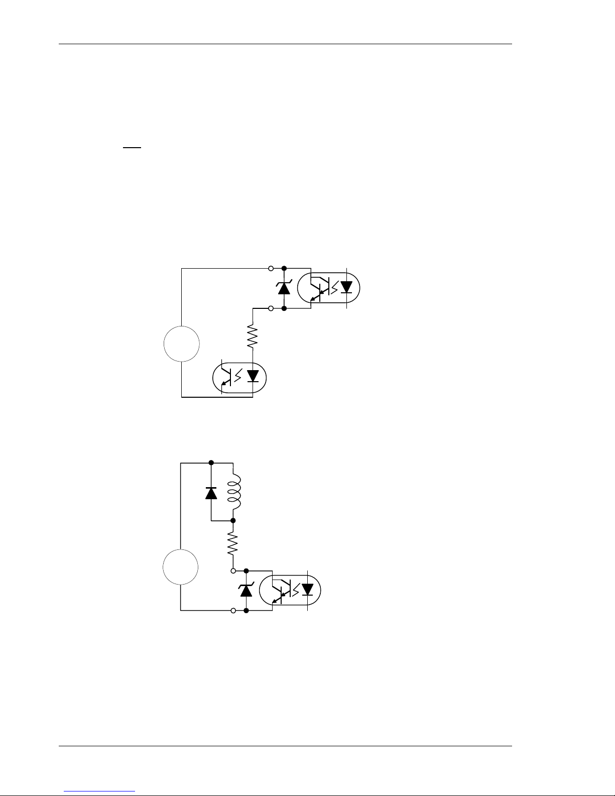
Wiring the Drive 05/2008 Danaher Motion
52 S200-VTS Product Manual
6.7.2.1 Default Output Functions
The list below describes the factory defaults for each of the outputs.
DOUT1
(FAULT)
Output 1: This output provides the FAULT state of the
drive. When the drive is powered and not faulted, the
output transistor is turned ON. When the drive is faulted or
not powered, the output transistor is turned OFF.
DOUT2
(RUN)
Output 2: This output provides the RUN state of the drive.
When the drive is powered, not faulted and enabled, the
output transistor is turned ON. When the drive is faulted,
not enabled or not powered, the output transistor is turned
OFF. This output indicates when the drive is capable of
running the motor.
6.7.2.2 Outputs Driving Typical Loads
Both the collector and emitter of the phototransistor are on J4, providing the capability to drive
either sinking or sourcing loads.
Sinking Load
Current Limiting Resistor
50 mA MAX
External
Power Supply
30 VDC MAX
DC
+
-
An optoisolator is being driven in this example. The current through the output needs to be
limited to 50 mA or less, which is accomplished by selecting an appropriate current limiting
resistor. The voltage of the external power source needs to be 30 VDC or less, and can be the
same source used to provide power to the inputs.
Sourcing Load
Current Limiting Resistor
50 mA MAX
External
Power Supply
30 VDC MAX
Relay
Coil
Clamp
Diode
DC
+
-
In this example, a relay coil is being driven. The current through the coil needs to be limited to
50 mA or less, which is accomplished by selecting an appropriate value of current limiting
resistor.
The voltage of the external power source needs to be 30 VDC or less and can be the same
source used to provide power to the inputs. A clamp diode must be added across the coil to
clamp the voltage during turn-off.

Danaher Motion 05/2008 Wiring the Drive
S200-VTS Product Manual 53
6.7.3 High Speed Input
High Speed Input
J4-10, 11
(Step or PWM)
The S200 has one high speed input for use with PWM input
commands or with Step Input in Position Mode.
J4-10
HSINP1+
J4-11
HSINP1-
221 Ω
2.21 k
The high speed input works directly with 5 V input, 3.0 to 6.0
V range, without the use of a current limiting resistor. To
operate the input with voltages higher than 5 V, an external
current limiting resistor is required in series with the input.
The input current should be in the range of 9 to 24 mA for
proper operation. The following table lists the recommended
current limiting resistors for supply voltages greater than 5 V.
Supply Voltage Current Limiting Resistor
5 V None
12 V 360 Ohms, ¼ watt, resistor
24 V 1000 Ohms, ½ watt, resistor
In Step-Dir Position Mode the transition edge from LED
current to no LED current yields a step count. The transition
edge from no LED current to LED current yields no action.
NOTE
Maximum step frequency is 1.5 MHz
Minimum pulse width is 250 ns
NOTE
For single ended operation, it is recommended that both wires (J4-10 and
J4-11) run in the cable be terminated at the control source (differential
noise).
High Speed Input
Differential Drive
A differential drive is recommended for the Step Input. To
provide maximum noise immunity, drive the high speed
input differentially from 5 V logic through twisted pair wiring.
The differential driver needs to deliver a minimum of 3.0 V
to the input terminals on J4. A CMOS driver is
recommended.
5 V Differential
Driver - CMOS
J4-11
HSINP1-
J4-10
HSINP1+
Twisted Pair
Wiring
3.0 V Min.

Wiring the Drive 05/2008 Danaher Motion
54 S200-VTS Product Manual
Sinking Load
For single ended operation, both terminals of the high speed input are available on J4, allowing
the input to be connected to either sinking or sourcing logic. The following diagram shows the
connections to drive the high-speed input from sinking logic.
External
4 - 30 VDC
Power Supply
Sinking Logic Output
from Field Device
External Current Limiting
Resistor for supply > 5.0 V
J4-10
HSINP1+
J4-11
HSINP1-
DC
+
-
Sourcing Load
The following shows the connections to drive the high-speed input from sourcing logic. The
power supply can be the same power source used to provide power for the general purpose
inputs.
External Current Limiting
Resistor for supply > 5.0 V
External
4 - 30 VDC
Power Supply
Sourcing Logic
Output from Field
Device
J4-11
HSINP1-
J4-10
HSINP1+
DC
+
-
6.7.4 SFD BAT+
J4-12
SFD BAT+
The SFD BAT+ terminal is an optional feature and is not
required for proper operation of the drive. It is only required if
battery backup of the multi-turn information is required from
the SFD. If the feedback device is not an SFD, then the
battery does nothing.
J4-13
I/O RTN
The I/O RTN is the ground reference for the SFD BAT+ input.
6.7.5 DAC Monitors
J4-14
DAC MON1
J4-15
DAC MON2
The DAC Monitors are general-purpose analog monitor
points. The output range is 0.5 to 4.5 V with a source
impedance of 2.9 kW, which limits the short circuit to I/O
RTN to 2 mA. Each DAC Monitor can be mapped by
software to one of a number of internal variables.
J4-13, 16, 23, 26
I/O RTN
/O RTN is the ground reference for the DAC MON, Analog
Command, Encoder output/inputs, and SFD BAT+. These
pins are electrically shorted together inside the drive.
Connect one of the I/O RTN pins to an earth ground point in the cabinet
reserved for single point grounding of all returns (drives and supplies) to
control common mode voltage.

Danaher Motion 05/2008 Wiring the Drive
S200-VTS Product Manual 55
6.7.6 Encoder Outputs/Inputs
J4-19
CH A OUT/IN
J4-20
CH A OUT/IN
J4-21
CH B OUT/IN
J4-22
CH B OUT/IN
Outputs
Channels A and B are RS-485 compliant differential I/O that can be
configured as either inputs or outputs. Default is as outputs. When
configured as outputs and with high resolution feedback such as the SFD
device, Channels A and B provide position signals generated from the
feedback device that emulate a quadrature encoder.
The outputs are buffered by 5.0 V, 75LBC170 type RS-422 compatible line
drivers. Recommended load current is ±20 mA, which corresponds to a
line-to-line load resistance of 100 Ω. These outputs can handle shorts to
I/O RTN indefinitely without damage.
The resolution of the Encoder Outputs (number of pulses per motor
revolution), is set by S1 (rotary switch), as follows:
S1
Position
Encoder Pulses/Revolution
0 User settable1 (factory default = 500)
1 512
2 1000
3 1024
4 2000
5 2048
6 4096
7 5000
8 8192
9 10000
1
User settable non-volatile PPR via the serial port.
Possible PPR are:
128, 512, 1024, 2048, 4096, 8192, 16384, 32768,
125, 500, 1000, 2000, 2500, 5000, 10000, 20000
The maximum output line frequency is 2.5 MHz. Limit line frequency to below
1.25 MHz, which corresponds to quadrature count frequency below 5 MHz, for
robust operation.
NOTE
The emulated encoder output is only available when using a high
resolution feedback device such as the SFD feedback to the base unit
or Encoder feedback to the option card. The emulated encoder outputs
have no signals when there is only base unit 6-step feedback.
Inputs
Channels A and B can be configured as inputs by setting NV Parameter
PosCmdSrc to AQUADB. With NV Parameter OpMode set to Position and
PosCmdSrc to AQUADB, the motor shaft position command comes from the
quadrature decode of channels A and B input scaled by the ratio of NV
Parameters GearOut over GearIn. In Input mode, Channels A & B accept
quadrature position commands. The command signals need to be differential
quadrature signals.
Channel A leading B generates a CW position command while Channel B
leading A generates a CCW position command. The magnitude of the
command position is set by GearIn and GearOut. The maximum input line
frequency for reliable operation is 625 kHz, which corresponds to a maximum
quadrature pulse rate of 2.5 MHz.

Wiring the Drive 05/2008 Danaher Motion
56 S200-VTS Product Manual
J4-17, 18
CH Z OUT
CH Z OUT
The CH Z Output is only available when using SFD Feedback. These
two terminals function as a differential, TTL marker pulse. The output
pulse occurs once per motor shaft revolution, starting at feedback
device position = 0. Its width is one line width or two quadrature
encoder widths. The CH Z uses the same differential driver as
described for CH A and CH B.
Encoder
Phasing
Encoder Phasing for Clockwise Motor Rotation
Z
B
A
PosFB – EncOutZoffset = 0
6.7.7 Analog Command Input
ANA CMD
J4-24, 25
(+), (-) Inputs
This differential input accepts the analog command from the user. It
has a maximum single ended input range with respect to I/O RTN on
either input of –12.5 to +15.5 VDC, a differential input impedance of
> 300 kΩ, and a single ended impedance of > 150 kΩ. The
recommended full-scale differential command input range is ±10 V,
but the input can handle up to ±12 V to accommodate noise and
overshoot spikes. Default setup has ±10 V corresponding to ±Ipeak
or ± maximum velocity depending on the OpMode.
The offset, gain (including polarity), and low pass filter bandwidth of
this input are set by the following NV Parameters: CmdGain,
CmdOffset, and CmdF0 respectively and can be adjusted by the
PC setup software. Defaults are ±10 V range, 0 offset, 1500 Hz
bandwidth. Positive ANA CMD yields clockwise torque when
looking at the shaft at the front of the motor.
-
+
OP AMP
33.2 k 130 k
100 pf
33.2 k 130 k
100 pf
J4-26
J4-25
J4-24
I/O RTN
ANA
CMD +
ANA
CMD -
To
A/D
1.575 V
+
-
20 k
Z
Z
Vad
20 k
+
-
15.0 k
15.0 k
NOTE
Always connect I/O RTN (J4-26) to the signal ground of the
source. Failure to do so may result in erratic operation.
Both J4-24 and J4-25 need to be wired. For single ended
operation connect the unused input to the signal ground of the
source. Best signal fidelity uses a separate wire all the way back
to the source for the unused input connection to the source’s
signal ground.
The direction of rotation of the motor can be changed by
swapping the ANA CMD input connections or changing the sign
of the CmdGain NV Parameter.

Danaher Motion 05/2008 Wiring the Drive
S200-VTS Product Manual 57
6.8 J5 – Serial Port Connector
J5 a 6-pin RJ-12/RJ-11 connector provides RS-232 serial communication to the drive. The RS232 transceiver is an industry standard RS-232 configuration using the MAX3221.
16
(J5 Connector view from
front of drive)
Pin Description
J5-1 No Connection
J5-2 RX232
J5-3 I/O RTN
J5-4 I/O RTN
J5-5 TX232
J5-6 No Connection
Mating Connector Information
RJ12/RJ11 – Phone Style -Standard RJ12/RJ11 plug
J5-1, J5-6
No Connection
These terminals are not used or connected to the drive.
J5-2
RX232
RS-232 receiver input to the drive. This terminal connects to the user's
RS-232 transmitter output.
J5-3, J5-4
I/O RTN
These terminals are the common/ground connection for the RS-232
serial port. The ground from the user's RS-232 needs to connect to this
terminal. Cable shielding is also connected to this point.
J5-5
TX232
RS-232 Transmitter output from the drive. This terminal connects to the
user's RS-232 receiver input.
CAUTION
Do NOT use the serial connector/cable when using an S200
SynqNet Series Drive. SynqNet cables, not a serial cable, should
be used for communication between the drive and SynqNet
motion controller. If you connect to an S200 SynqNet Series Drive
using a serial cable and select 'Serial' instead of 'SynqNet' as the
Communications Mode in the S200Tools Communication Wizard,
the drive will appear configured in the interface, but the SynqNet
Options tab will not appear under the Drive Setup options.

Wiring the Drive 05/2008 Danaher Motion
58 S200-VTS Product Manual
6.8.1.1 Status LED
The Status LED is located below the Serial Port connector located at J5. Please see the
Drive
Fault Codes section for descriptions.
6.8.2 Serial Interface Specification
Parameter Specification
Baud rate
19,200
Electrical Interface
RS-232, Full duplex
Transfer format UART, 1 start bit (mark), 8 data bits, odd parity bit
and 1 stop bit (space).
6.8.3 RS-232 Wiring
Cable wiring diagrams for connecting to either 9 or 25-pin serial ports of most computers are
also shown.
NOTE
Pinouts vary among computer manufacturers. Check the
hardware reference manual for your machine before wiring.
25 Pin Female
3
2
7
5
2
3
To PC
To J5
on Drive
To J5
on Drive
2
3
5
5
2
3
9 Pin Female
To PC

Danaher Motion 05/2008 Wiring the Drive
S200-VTS Product Manual 59
6.9 SynqNet Option Card Wiring
A
U
X
F
B
J14
2
1
3
4
5
FCOM+/Z+/DATA+
6
FCOM-/Z-/DATA-
7
AUX PTC
8
9
+5V I/O
10
11
12
13
14
15
I/O RTN/PTC RTN
I/O RTN
AUX A+
AUX A-
AUX B+
AUX CU
I/O RTN
AUX CV/CLOCK+
AUX CW/CLOCK-
+5V I/O
D
I
S
C
R
E
T
E
I
O
J13
OINP COM
2
1
3
4
OINP3 (NEGLIMIT IN)
5
GP RS422 IN3+
6
GP RS422 IN3-
7
OOUT1+
8
9
I/O RTN
10
11
12
13
14
15
GP RS422 IN0+
GP RS422 IN0-
GP RS422 IN1+
GP RS422 IN1-
OINP1 (HOME IN)
OINP2 (POSLIMIT IN)
I/O RTN
OINP4 (NODE DISABLE)
OOUT1-
CONN_TD0+
1
2
3
4
5
6
7
8
CONN_TD0CONN_RD0+
CONN_TTERM0
CONN_TTERM0
CONN_RD0CONN_RTERM0
CONN_RTERM0
J11
AUX B-
CONN_RD1+
1
2
3
4
5
6
7
8
CONN_RD1CONN_TD1+
CONN_RTERM1
CONN_RTERM1
CONN_TD1CONN_TTERM1
CONN_TTERM1
J12
SynQNet In
Syn
QNet Out
1
6
11
5
10
15
1
6
11
5
10
15

Wiring the Drive 05/2008 Danaher Motion
60 S200-VTS Product Manual
6.10 J11 – SynqNet IN Port Connector
J11 is a Standard CAT5 connector.
(J11 Connector view from front of drive.)
Pin Description
J11-1 CONN_TD0+
J11-2 CONN_TD0-
J11-3 CONN_RD0+
J11-4 CONN_TTERM0
J11-5 CONN_TTERM0
J11-6 CONN_RD0-
J11-7 CONN_RTERM0
J11-8 CONN_RTERM0
- SHLD
Mating Connector Information
8-Pin Male PN 5-557315 (not shielded)
8-Pin Male PN 5-569552-3 (shielded)
6.10.1 SynqNet LEDs
Pin Meaning Description
ON = Tx and Rx active (cyclic phase)
BLINK = Tx only active (discovery phase)
STAT
Network Status Activity
OFF = Idle (shutdown phase)
ON = Link Active
LNK
Link Activity
OFF = Link Inactive

Danaher Motion 05/2008 Wiring the Drive
S200-VTS Product Manual 61
6.11 J12 – SynqNet OUT Port Connector
J12 is a Standard CAT5 connector.
(J12 Connector view from front of drive.)
Pin Description
J12-1
CONN_RD1+
J12-2
CONN_RD1-
J12-3
CONN_TD1+
J12-4
CONN_RTERM1
J12-5
CONN_ RTERM1
J12-6
CONN_TD1-
J12-7
CONN_TTERM1
J12-8
CONN_ TTERM1
-
SHLD
Mating Connector Information
8-Pin Male PN 5-557315 (not shielded)
8-Pin Male PN 5-569552-3 (shielded)
6.11.1 SynqNet LEDs
Pin Meaning Description
ON = Repeater on, network cyclic
BLINK = Repeater on, network not cyclic
RPTR Repeater
OFF = Repeater off, power off, or reset
ON = Link Active
LNK Link Activity
OFF = Link Inactive

Wiring the Drive 05/2008 Danaher Motion
62 S200-VTS Product Manual
6.12 J13 – Discrete I/O Connector
5
10
15
1
6
11
J13 is a Standard D-Sub 15-pin Male connector.
(J13 Connector view from front of drive.)
Pin Description
J13-1 OINP COM
J13-2 OINP1 (HOME IN)
J13-3 OINP2 (POSLIMIT IN)
J13-4 OINP3 (NEGLIMIT IN)
J13-5 OINP4 (NODE_DISABLE)
J13-6 GP RS422 IN3+
J13-7 GP RS422 IN3-
J13-8
OOUT1+
J13-9
OOUT1-
J13-10 I/O RTN
J13-11 I/O RTN
J13-12 GP RS422 IN0+
J13-13 GP RS422 IN0-
J13-14 GP RS422 IN1+
J13-15 GP RS422 IN1-
Mating Connector Information
15-Pin Female High Density D-Sub
NorComp 180-015-202-001 – Female D-Sub connector solder
NorComp 978-009-020-121 – Metalized plastic back shell kit
Refer to www.norcomp.net.
The optically isolated digital I/O on connector J13 is based on the exact same circuitry used on
the base unit on connector J4. For detailed electrical specifications and information on how to
interface to this I/O refer to Sections
6.7.1 General Purpose Inputs and 6.7.2 General Purpose Outputs.
J13 also includes 3 channels of very fast RS-422 compatible direct coupled differential digital
inputs that can be used for very high speed registration or probing functions.

Danaher Motion 05/2008 Wiring the Drive
S200-VTS Product Manual 63
6.12.1 J13 – Discrete I/O Connection Schematic
+3_3V
GNDD
D
+3_3V
+3_3V
+3_3V
PS2805-4
+3_3V
+3_3V
+3_3V
GNDD
D
GNDD
D
GND
VCC
DS26LV32ATM
DS26LV32SO16
+--+-+-
+
GNDD
D
+3_3V
GNDD
D
SHLD1
SHLD2
PE
BZX84-C33
SCHEMATIC
NONE
SQNODE S200 OPTION CARD
1
76543
A
B
C
D
E
F
G
H
UNLESS OTHERWISE SPECIFIED:
RESISTORS: VALUES ARE OHMS, 1/4W,+/-1%
CAPACITORS: VALUES ARE IN MICROFARADS
DIODES :ARE 1N914B
SEE CUSTOMIZATION SHEET FOR FEATURES
DATE:
FILE:
SCALE
APP'D:
APP'D:
CHK:
DWN:
NOTES:
PACIFIC SCIENTIFIC
TITLE
REVDRAWING NO.
SIZE
D
SHEET OF
APPRCKREVISION RECORDDATE SYM DR
SEE SHEET ONE
6 87543
8
Motion Technology Division
110 Fordham Road, Wilmington MA 01887
BZXB4-C33
A NC
K
SOT23
IO CONNECTOR
RS-422 Receivers for Position_Capture
Receiver delay 35ns
Input common mode voltage range: -7V to +7V
(INHIBIT+)
(INHIBIT-)
(ENABLE)
|Voff| Spec.: < 1.5V
0.65mA to 6.7mA
|VOn| Spec.: 4.0V to 30V
MALE PINS
I/O RTN
OINP4
GP_RS422_IN1+
GP_RS422_IN2-
OINP3
GP_RS422_IN2+
OINP2
GP_RS422_IN0+
GP_RS422_IN3-
OINP1
I/O RTN
GP_RS422_IN3+
OINP COM
GP_RS422_IN-
GP_RS422_IN0-
DINPx to DINP_COM
DO NOT STUFF
DO NOT STUFF
I/O CIRCUITS
3-105-030301
11
J13-IO 1
12-17-2007_14:04
9DS0-0114
.
GP_RS422_IN3-
GP_RS422_IN3+
GP_RS422_IN2+
GP_RS422_IN2-
0
R108
R75
0
GP_RS422_IN2-
23
41
U15
3
1
D2
33V
150
R73
OOUT1
GP_RS422_IN2+
C118
1000PF
10
11
12
13
14
15
2
3
4
5
6
7
8
9
16
17
1
J13
100NF
C67 C69
100NF 100NF
C70
DINP_COM
NODE_DISABLE
POS_LIMIT
HOME
DINP_COM
NODE_DISABLE_IN
NEGLIMIT_IN
POSLIMIT_IN
HOME_IN
R57
4.32K
4.32K
R56
R55
4.32K
4.32K
R54
C46
4700PF
R60
4.64K
4.64K
R81
C61
4700PF
C45
4700PF
R83
4.64K
4.64K
R84
R53
4.64K
GP_RS422_IN3-
NEG_LIMIT
R61
46.4K
GP_RS422_IN3
GP_RS422_IN1-
GP_RS422_IN1+
GP_RS422_IN0-
GP_RS422_IN0+
GP_RS422_IN2
2
136
7
5
10
9
11
14
15
13
4
8
16
12
U14
GP_RS422_IN0
GP_RS422_IN1
GP_RS422_IN1-
GP_RS422_IN2+
GP_RS422_IN2-
GNDD
GNDD
GP_RS422_IN0-
GP_RS422_IN1+
HOME_IN
POSLIMIT_IN
NEGLIMIT_IN
NODE_DISABLE_IN
GP_RS422_IN3+
1
2
3
4
5
6
7
8
10
12
14
16
11
13
15
9
U12
C44
4700PF
46.4K
R63
R64
46.4K
46.4K
R65
GP_RS422_IN0+
4.64K
R52

Wiring the Drive 05/2008 Danaher Motion
64 S200-VTS Product Manual
6.13 J14 – AUX FB Connector
1
6
11
5
10
15
J14 is a Standard D-Sub 15-pin Female connector.
(J14 Connector view from front of drive.)
Mating Connector Information
15-Pin Female High Density D-Sub
NorComp 180-015-102-001 – Male D-Sub connector solder
NorComp 978-009-020-121 – Metalized plastic back shell kit
Refer to www.norcomp.net.
6.13.1 Auxiliary Feedback Device Port
Run FB Type
X Incremental Encoder
X X Incremental Encoder + Halls
AKM Motor Feedback Options:ED, EE, DF, EG, EM, EH, EN, EJ
X 1 Vp-p Sin-Cos 65536x Interpolator
X X 1 Vp-p Sin-Cos 65536x Interpolator + Halls
X X EnDat 2.1 Sin-Cos Encoder Single-turn absolute
AKM Motor Feedback Option DA or other EnDat 2.1
X X EnDat 2.1 Sin-Cos Encoder Multi-turn Absolute
AKM Motor Feedback Option DB or other EnDat 2.1
X X
EnDat 2.2 Encoders operating in 2.1 compatibility mode both
rotary and linear including absolute types
Run - Commutate the motor and close the servo loops.
FB - Use as a secondary feedback to SynqNet master.
Pin Description
J14-1 AUX CU
J14-2 AUX CV/CLOCK+
J14-3 AUX CW/CLOCK-
J14-4 +5V I/O
J14-5 I/O RTN
J14-6 FCOMZ+ / DATA+
J14-7 FCOMZ- / DATA-
J14-8
AUX PTC
J14-9 I/O RTN
J14-10 +5V I/O
J14-11 I/O RTN
J14-12 AUX A+
J14-13 AUX A-
J14-14 AUX B+
J14-15 AUX B-

Danaher Motion 05/2008 Wiring the Drive
S200-VTS Product Manual 65
6.13.2 Auxiliary Feedback Sin-Cos Interpolation Scaling
The J14 1 Vp-p analog Sin-Cos feedback interface has a 65536x (16 bit) interpolator that is
followed by a programmable scalar to create the final measured position in counts. The
following diagram shows the scaling path. When J14 is used a an Auxiliary or second feedback
the user is free to select whatever value for the scaling parameter AuxFBDivisor best suits the
application. However, if the NV parameter FBSrc is set to Option Card, then AuxFBDivisor
must be set to the specific value which will properly electronically commutate the motor work.

Basic Configuration 05/2008 Danaher Motion
66 S200-VTS Product Manual
7 BASIC CONFIGURATION
When connected to a motor equipped with the Smart Feedback Device (SFD), the S200 drive
will automatically configure most of its operating parameters. For many applications requiring
an analog torque or analog velocity block, no additional set up beyond the setting of the two
switches is required to fully commission the drive. For such cases, connection to a computer to
commission the drive is not required. The quick setup is useful for simplifying machine field
upgrades/repairs and for reducing spare part inventory. See
Configuring with SFD Feedback.
The drive can also be configured for a simple analog Torque/Current control with 6-Step (Hall)
Feedback type by simply setting the switches. See
Configuring Current Mode with 6-Step (Hall)
Feedback.
The S200 drive has many advanced capabilities to aid machine design through its diagnostic
and measurement capabilities accessed through the Windows compatible S200Tools GUI
utility. The drive also has many advanced motion capabilities that can be set up through the
S200Tools utility. For example, if desired, the settings of the switches can be overridden in
drive non-volatile memory to eliminate any accidental miss-adjustment of the drive in the field.
See the
Advanced Configuration section for more details.
7.1 Switch Settings
The configuration switches S1 and S2 are located on the top of the drive. Although the drive
can be configured to not use the switches, the factory default configuration uses the switches
for selecting Torque/Current versus Velocity operational mode, SFD or 6-step feedback device,
and emulated encoder line count.
Dow n/C lo se d
Up/Open
1234
S1
S2
0
1
2
3
4
5
6
7
8
9
7.1.1 S2 - DIP Setup Switch
S2 is a 4-position DIP switch. Switch positions 1 and 2 can set the operational mode and
feedback types when enabled. Setting the drive parameters as shown in the following table
enables the switch and is the factory default configuration. Switch positions 3 and 4 are
reserved for future functionality and should be left in the down/closed factory default position.
Switch State
Switch
Position
Parameter
Setting
Function
Down/Closed Up/Open
S2-1
OpMode =
SetupS2-1
Operational
Mode
Torque/Current
Control
Velocity
Control
S2-2
CommMode
= SetupS2-2
Feedback
Type
SFD 6-Step
S2-3 Reserved Default Reserved
S2-4 Reserved Default Reserved
NOTE
Drive parameter settings can override the S2 switch settings. To enable S2
for setup verify that the following drive parameters are set as shown below.
The factory default is to ship the drive with the switches enabled:
Parameter Value
OpMode
SetupS2-1
CommMode
SetupS2-2

Danaher Motion 05/2008 Basic Configuration
S200-VTS Product Manual 67
7.1.2 S1 - Rotary Setup Switch
Switch S1 is a 10-position rotary switch. The function of switch S1 depends on the feedback
mode in which the drive is configured.
7.1.2.1 S1 Function with SFD Feedback
When using the Smart Feedback Device (SFD), S1 sets the emulated encoder line count.
S1
Position
Emulated Encoder
Lines/Revolution
S1 Position
Emulated Encoder
Lines/Revolution
0
User settable
1
(factory default = 500)
5 2048
1 512 6 4096
2 1000 7 5000
3 1024 8 8192
4 2000 9 10000
1
S1 position 0 allows setting the non-volatile line count via the drive
parameter EncOut to any of the following values:
128, 512, 1024, 2048, 4096, 8192, 16384, 32768
125, 500, 1000, 2000, 2500, 5000, 10000, 20000
The value written replaces the factory default value listed in position 0 of
the table.
NOTE
The emulated encoder output is only available when using
SFD feedback to the base unit or a high-resolution feedback
device connected to the option card.

Basic Configuration 05/2008 Danaher Motion
68 S200-VTS Product Manual
7.1.2.2 S1 Function with 6-Step Feedback
In 6-step mode, S1 sets the current loop proportional gain, KIP. Set S1 to the value listed in the
table for your drive type and motor inductance. Consult the factory if the motor inductance is
lower or higher than what can be accommodated by S1. An incorrect setting of KIP can cause
current loop instability or oscillation potentially resulting in damage to the drive or application.
Motor Inductance Table for 6-Step Commutation (L in mH)
AC Input Drive DC Input Drive S1
S20260 S20360 S20660 S20330 S20630
Position
User
Settable
1
(factory
default =
96.932)
User
Settable1
(factory
default =
48.416)
User
Settable1
(factory
default =
24.208)
User
Settable1
(factory
default =
12.104)
User
Settable1
(factory
default =
6.052) 0
1
6.17 - 9.03 3.09 - 4.50 1.55 - 2.25 0.52 - 0.75 0.27 - 0.38 1
9.04 -
13.39
4.51 - 6.69 2.26 - 3.34 0.76 - 1.11 0.39 - 0.56 2
13.40 -
19.56 6.70 - 9.78 3.35 - 4.89 1.12 - 1.63 0.57 - 0.81 3
19.57 -
28.89
9.79 -
14.44
4.90 - 7.22 1.64 - 2.41 0.82 - 1.20 4
28.90 -
43.34
14.45 -
21.67
7.23 -
10.83
2.42 - 3.61 1.21 - 1.80 5
43.35 -
63.80
21.68 -
31.90
10.84 -
15.95 3.62 - 5.32 1.81 - 2.65 6
63.81 -
95.11
31.91 -
47.55
15.96 -
23.76 5.33 - 7.92 2.66 - 3.96 7
95.12 -
144.49
47.56 -
72.24
23.77 -
36.12
7.93 -
12.04
3.97 - 6.02 8
144.50 -
216.74
72.25 -
108.4
36.13 -
54.20
12.05 -
18.06 6.03 - 9.03 9
1
S1 position 0 allows setting the non-volatile KIP via the serial port to any
valid value in 6-Step mode. The value written will replace the default value
listed in position 0 of the table.
7.1.3 S11, S12 - Rotary SynqNet ID Switches
The SynqNet ID switches can be used to help distinguish and differentiate a drive on the
network by assigning a unique ID to the drive.
To set a SynqNet ID to an S200 drive, turn the S11 LSB (Least Significant Bit) and S12 MSB
(Most Significant Bit) switches to a desired letter/number combination.
The SynqNet ID can then be read using the following utilities: Motion Console and Version.exe
Utility.

Danaher Motion 05/2008 Basic Configuration
S200-VTS Product Manual 69
7.1.3.1 Motion Console
In the SqNode Summary window, under the Info tab, the SynqNet ID is displayed in the Switch
ID field. See screenshot below.
SYNQNET ID
S11 = 5
S12 = A
7.1.3.2 Version.exe Utility
The version.exe utility also displays the Switch ID field. See screenshot below.
SYNQNET ID
S11 = 5
S12 = A

Basic Configuration 05/2008 Danaher Motion
70 S200-VTS Product Manual
7.2 Configuring for Brush Motors
NOTE
With a SynqNet option card the S200 Drive must be set with FBSrc =
Base Unit.
To drive a brush motor connect to the S200 as shown below.
S200
Brush Motor Wiring
1
2
1
2
3
4
FEEDBACK
6
5
4
3
J3
J2
MOTOR
POWER
Motor +
Motor -
PE
No
Connection
BRUSH
MOTOR
To finish configuring the S200 to drive a brush motor, set the following parameters using the
S200Tools utility. Once configured, the parameters should be saved to non-volatile MEMORY
(click the NV Save button). The configuration will then be recalled on drive power up. Refer to
Advanced Configuration for detailed descriptions of the parameters. The relevant parameters
are listed in the table below.
Parameter Value
CommMode
Brush
CommOff
0 Degrees
OpMode
Torque/Current
Or
SetupS2-1 with switch S2-1 set to the down position labeled, I
on the drive.
KIP
Set directly with the serial port when S1 is set to position 0.
Or
Set S1 to the appropriate position for the inductance of the
motor be used, refer to
S1 Function with 6-Step Feedback.
I2TF0
Set to the motor’s thermal time constant.
I2TTrip
Set to the motor’s continuous current rating.
IlmtPlus
ILmtMinus
Set to the lower of 100% or the percent of the motor’s peak
current rating divided by the drives peak current.
CmdSrc
Selects Analog, PWM, or Command variable for command.
CmdGain
Sets the command gain for the command input.
CmdOffset
Sets the command offset for the command input.
CMDF0
Sets the filtering on analog input commands.
EnInhibitCW
EnInhibitCCW
Enables the hardware over travel limits.

Danaher Motion 05/2008 Basic Configuration
S200-VTS Product Manual 71
7.3 Configuring with 6-Step (Hall) Feedback
7.3.1 6-Step Feedback Wiring
1
2
HALL
1
2
3
4
FEEDBACK
6
5
4
3
MOTOR
+5 RTN
+5V
CU
CV
CW
J3
J2
MOTOR
POWE R
PHASE U
PHASE V
PHASE W
PE
7.3.2 6-Step Torque/Current Mode
In 6-Step mode with Hall or Hall equivalent feedback, the drive can be configured either using
the S200Tools utility or the S1 and S2 switches. Configuring the drive with the S200 Tools
provides the advantage of setting the drive's current limits and motor thermal protection. When
using S200Tools the configuration parameters should be saved to non-volatile memory to allow
the configuration to be recalled on power up.
To configure the drive for 6-Step feedback set the following parameters:
Parameter Value
CommMode
SetupS2-2 (Default value) with switch S2-2 set to the up position labeled, 6 on
the drive.
or
6-Step
CommOff
0 Degrees (Default value)
OpMode
SetupS2-1 (Default value) with switch S2-1 set to the down position labeled, I
on the drive.
or
Torque/Current
KIP
Set directly with the serial port when S1 is set to position 0
or
Set S1 to the appropriate position for the inductance of the motor be used,
refer to
Configuring Current Mode with 6-Step (Hall) Feedback.
I2TF0
Set to the motor’s thermal time constant.
I2TTrip
Set to the motor’s continuous current rating.
ILmtPlus
ILmtMinus
Set to the lower of 100% or the percent of the motor’s peak current rating
divided by the drives peak current.
CmdSrc
Sets the source of the command, analog or command variable.
CmdGain
Sets the command gain for the command input.
CmdOffset
Sets the command offset for the command input.
CmdF0
Sets the filtering on analog input commands.

Basic Configuration 05/2008 Danaher Motion
72 S200-VTS Product Manual
The following are optional parameters that can be set.
Parameter Function
EncOut
Sets the line count of the emulated encoder output. With 6-Step feedback the
emulated encoder output works by interpolating between the edges. So, at low
speeds signal quality will be poor.
EnInhibitCW
EnInhibitCCW
Enables the hardware over travel limits.
7.3.3 6-Step Velocity Mode
In 6-Step mode with Hall or Hall equivalent feedback, the drive can be configured to control
shaft velocity. But, because of the coarse resolution of 6-Step feedback the velocity bandwidth
and smoothness will not be as good as other feedback options.
To configure the drive for 6-Step feedback Velocity mode set the following parameters:
Parameter Value
CommMode
SetupS2-2 (Default value) with switch S2-2 set to the up position labeled, 6 on
the drive.
or
6-Step
CommOff
0 Degrees (Default value)
OpMode
Velocity
or
SetupS2-1 with switch S2-1 set to the up position labeled, V as shown on the
drive.
ARF0
ARF1
Single pole filters in the velocity loop forward path. Set to accommodate the
effects of mechanical resonance
KVI
Sets the velocity loop break out frequency from integral to proportional
compensation.
CmdSrc
Selects Analog, PWM, or Command variable for command.
CmdGain
Sets the command gain for the command input.
CmdOffset
Sets the command offset for the command input.
CmdF0
Sets the filtering on analog input command.
The following are optional parameters that can be set.
Parameter Function
EncOut
Sets the line count of the emulated encoder output. With 6-Step feedback the
emulated encoder output works by interpolating between the edges. So, at low
speeds signal quality will be poor.
EnInhibitCW
EnInhibitCCW
Enables the hardware over travel limits.

Danaher Motion 05/2008 Basic Configuration
S200-VTS Product Manual 73
7.4 Configuring with SFD Feedback
7.4.1 SFD Motor Parameters
When the drive is powered up and connected to a motor with SFD feedback, the drive will
automatically configure itself for the attached motor by loading the default motor parameters.
The default motor parameters provide robust performance of current and velocity loops with
optimized settings to protect the motor from thermal overload. For most applications, these
default motor parameter settings are recommended because they provide excellent
performance and require no additional tuning. To use the default motor parameters verify that
SelSFDParam is set to SFD, which is the factory default setting.
If the response time and/or stability of the system needs to be further optimized for the specific
application, the motor parameters will need to be modified. To modify the motor parameters, set
SelSFDParam to Drive. This setting unlocks the motor parameters and allows the parameters
to be individually set with the S200Tools utility. The modified motor parameters will need to be
saved to the drive’s non-volatile memory (click the NV Save button) to ensure that the changed
settings are loaded when the drive is powered up.
CAUTION
Incorrect motor parameter settings can cause damage to the motor and/or drive.
The motor parameters need to be set correctly to match the drive to the motor. The
correct parameter settings ensure:
The drive is matched to the motor inductance and pole count.
The current and velocity loops are stable with good bandwidth.
The motor is protected from thermal overload.
NOTE
A good starting point to setting the motor parameters is to obtain the default motor
parameters and then edit only the parameters that need to be changed
Using the S200 Tools, set SelSFDParam to SFD, this loads the default motor
parameters.
Next, set SelSFDParam to DRIVE. This will allow the motor parameters to be
edited. Change only the parameters you are looking to optimize.
When fini sh ed setting the motor parameters (and any other parameters),
save the parameters to NV Memory by clicking the NV Save button.
The following drive setup parameters controlled by
SelSFDParam:
Parameter Value
KVP
Velocity loop proportional gain.
KIP
Current loop proportional gain.
DPoles
Drive pole pairs.
I2TF0
Speed of response for motor transient thermal protection.
I2TTrip
Fault trip level for motor transient thermal protection.
IlmtPlus,
IlmtMinus
Clamps drive maximum Iout based on motor Ipeak.

Basic Configuration 05/2008 Danaher Motion
74 S200-VTS Product Manual
7.4.2 SFD Torque/Current Mode
The S200 can drive a brushless motor in Torque/Current Mode using SFD Feedback. The drive
can be configured either with the S200Tools over the serial port or configured using the S1 and
S2 switches. Configuring the drive with the S200Tools utility provides increased flexibility in
setting parameters that are not available through the setup switches. When using the
S200Tools utility, the configuration parameters should be saved to non-volatile memory (click
the NV Save button) to allow the configuration to be recalled on power up.
To configure the drive for Current Mode with SFD feedback, set the following parameters:
Parameter Value
CommMode
SetupS2-2 (Default value) with switch S2-2 set to the
down position labeled, S on the drive.
or
SFD
CommOff
0 Degrees – for AKM motor series, check with your sales
representative for the correct commutation offset angle for
other motor series.
OpMode
SetupS2-1 with switch S2-1 set to the down position
labeled, I, on the drive.
or
Current
SelSFDParam
SFD (Default value) – recommended setting.
This setting will automatically set the motor parameters.
To change motor parameters refer to Configuring with
SFD Feedback Motor Parameters.
CmdSrc
Sets the source of the command.
CmdGain
Sets the command gain for the command input.
CmdOffset
Sets the command offset for the command input.
CMDF0
Sets the filtering on analog input commands.
The following are optional parameters that can be set.
Parameter Function
EncOut
Sets the line count of the emulated encoder output.
EnInhibitCW
EnInhibitCCW
Enables the hardware over travel limits.

Danaher Motion 05/2008 Basic Configuration
S200-VTS Product Manual 75
7.4.3 SFD Velocity Mode
The S200 can drive a brushless motor in Velocity Mode using SFD Feedback. The drive can be
configured either with the S200 tools over the serial port or configured using the S1 and S2
switches. Configuring the drive with the S200Tools utility provides increased flexibility in setting
parameters that are not available through the setup switches. When using the S200Tools utility,
the configuration parameters should be saved to non-volatile memory (click the NV Save
button) to allow the configuration to be recalled on power up.
To configure the drive for SFD feedback set the following parameters:
Parameter Value
CommMode
SetupS2-2 (Default value) with switch S2-2 set to the
down position labeled, S on the drive.
or
SFD
CommOff
0 Degrees – for AKM motor series. Check with your sales
representative for the correct commutation offset angle for
other motor series.
OpMode
Velocity
or
SetupS2-1 with switch S2-1 set to the up position labeled,
V as shown on the drive.
SelSFDParam
SFD (Default value) – recommended setting
This setting automatically sets the motor parameters.
KVP is set for 75 Hz nominal velocity loop bandwidth with
an unloaded motor.
To change KVP or other motor parameters, refer to
Configuring with SFD Feedback Motor Parameters.
ARF0
ARF1
Single pole filters in the velocity loop forward path. Set to
accommodate the effects of mechanical resonance
KVI
Sets the velocity loop break out frequency from integral to
proportional compensation.
CmdSrc
Selects Analog, PWM, or Command variable for
command.
CmdGain
Sets the command gain for the command input.
CmdOffset
Sets the command offset for the command input.
CmdF0
Sets the filtering on analog input command.
The following are optional parameters that can be set.
Parameter Function
EncOut
Sets the line count of the emulated encoder output.
EnInhibitCW
EnInhibitCCW
Enables the hardware over travel limits.

Basic Configuration 05/2008 Danaher Motion
76 S200-VTS Product Manual
7.4.4 SFD Position Mode
The base S200 can drive a motor in Position Mode using SFD Feedback. The source of the
command can either be Step and Direction, or A,B differential quadrature signals. The drive
needs to be configured using the S200Tools utility. The configuration parameters should be
saved to non-volatile memory (click the NV Save button) to allow the configuration to be
recalled on power up.
To configure the drive for SFD feedback set the following parameters:
Parameter Value
CommMode
SetupS2-2 (Default value) with switch S2-2 set to the
down position labeled, S on the drive.
or
SFD
CommOff
0 Degrees – for AKM motor series. Check with your sales
representative for the correct commutation offset angle for
other motor series.
OpMode
Position
PosCmdSrc
Selects the source of the command, either Step-Dir or
AquadB.
GearIn
GearOut
Sets the distance the shaft moves for each input position
command pulse/count.
KPP
Sets the proportional gain of the position loop.
KVFF
Sets the feed forward gain of the derivative or the position
command to the internal velocity command.
SelSFDParam
SFD (Default value) – recommended setting
This setting will automatically set the motor parameters.
KVP will be set for 75 Hz nominal velocity loop bandwidth
with an unloaded motor.
To change KVP or other motor parameters refer to
Configuring with SFD Feedback Motor Parameters.
KVI
Sets the velocity loop break out frequency from integral to
proportional compensation.
ARF0
ARF1
Single pole filters in the velocity loop forward path. Set to
accommodate the effects of mechanical resonance.
The following are optional parameters that can be set.
Parameter Function
EncOut
Sets the line count of the emulated encoder output.
NOTE: Emulated Encoder Outputs are not available when
the PosSrcCmd is set to AQuadB.
EnInhibitCW
EnInhibitCCW
Enables the hardware over travel limits

Danaher Motion 05/2008 Basic Configuration
S200-VTS Product Manual 77
7.5 Reversing Motion Direction
In order to reverse the motion direction of the drive, the command to the drive needs to be
reversed. In addition, the emulated encoder output polarity needs to be reversed if an external
controller is using the emulated encoder outputs for feedback.
To reverse the command to the drive in Torque or Velocity Modes either change the wiring or
change the parameters:
CmdSrc Setting Wiring Method Parameter Method
Analog Command Swap the analog
command connections
(J4-24 and J4-25)
Change the sign of
CmdGain
Command Variable None
Change the sign of
Command
PWM Input Swap the PWM
connections (J4-10 and
J4-11)
Change the sign of
CmdGain
To reverse the command to the drive in Position Modes:
PosCmdSrc Setting Wiring Method
PosCmdSrc = AQuadB
Reverse the Ch A input to the drive by swapping J4-19
and J4-20.
PosCmdSrc = Step-Dir
The Direction command, J4-5, to the drive needs to be
inverted by the user’s controller.
To reverse the
Emulated Encoder Outputs from the drive:
• Reverse the Emulated Encoder Outputs if the external control loops use the emulated
encoder outputs for feedback.
• Swap the CHA and CHA/ emulated encoder outputs (J4-19 and J4-20) going to the
external controller.

Advanced Configuration 05/2008 Danaher Motion
78 S200-VTS Product Manual
8 ADVANCED CONFIGURATION
The S200 is shipped with a factory configuration that is designed to work with a Smart
Feedback Device (SFD) equipped motor to implement an analog commanded Torque/Current
block.
• The +10 V input (factory configuration) yields a maximum clockwise torque/current.
• The –10 V input yields a maximum counter clockwise torque/current.
By adjusting the rotary switch (S1) to set the emulated quadrature encoder output, a completed
setup of the drive is now ready for many applications.
To configure the drive as an analog velocity loop with medium velocity loop bandwidth/stiffness,
adjust the DIP switch (S2) so that pin 1 is in the up position.
If this functionality serves the application need, the factory setup can be used as is in an
application.
For applications other than the two standard configurations described above, such as using a
PWM digital line for the command or implementing a position loop with Step and Direction
command, the drive configuration will have to be customized through the Windows® PC
compatible setup software called, S200Tools.
The rest of this chapter describes the S200 configuration options through diagrams of the
control loops, reference lists of setup parameters with their definitions and range, and further
explanations of drive capabilities.

Danaher Motion 05/2008 Advanced Configuration
S200-VTS Product Manual 79
8.1 Base Drive Torque/Velocity Control Block Diagram
2 Pole
Low Pass
Filter
CmdF0
CmdSrcCommand
Ana Cmd +
CmdSrc
X
xxxx
NV Setup
Parameter
J4-24
Σ
Reset Hold
Velocity Loop
Integrator
OpMode
2π* .
s
ILmtMinus
ILmtPlus
Net
Velocity
Command
Arms
+=CW
Trq/I
Velocity
or
Position
IFB
+
-
Net Drive
Enable
xxxx
Variable
Measured
Feedback
Velocity Feedback
Rad/sec
Current
Arms
Clamp
On
Ana Cmd -
J4-25
Σ
-
+
HSInp1 +
J4-10
HSInp1 -
J4-11
PWM
CmdGain
Analog
Serial
Σ
CmdOffset
+
+
CmdIn
2 Pole
Low Pass
Filter
ARF 0 ARF1
Σ
+
+
VelErr
ICmdKVP
KVI
OpMode
Velocity
or
Trq/I
+=CW
Net
Torque
Command
Analog
or
PWM
VelCmd
Position
Position
VelFB

Advanced Configuration 05/2008 Danaher Motion
80 S200-VTS Product Manual
8.2 Base Drive Position Control Block Diagram
HSINP1 +
PosCmdSrc
xxxx
NV Setup
Parameter
J4-10
Σ
Net
Position
Command
Rad/Sec
+
-
xxxx
Variable
Measured
Feedback
Position Feedback
Rad
HSINP1 -
J4-11
AQuadB
Step-Dir
Σ
+
+
PosErr
VelCmd
Position
KPP
Net
Velocity
Command
PosFB
DINP4
J4-5
DINP COM
J4-1
CH A OUT/IN +
J4-19
CH A OUT/IN -
J4-20
CH B OUT/IN +
J4-21
CH B OUT/IN -
J4-22
Step-
Direction
Decode
Opto
Inputs
Quadrature
Decode
RS-485
Inputs
Digital
Accum
Digital
Accum
200 nSec 6.4 µSec
Delta
d
dt
GearOut
GearIn
6.4 µSec
819.2 µSec
Delta
d
dt
100
KVF F
+=CW
Rad
Counts
to
Rad
Counts
Step
Dir
2π* .
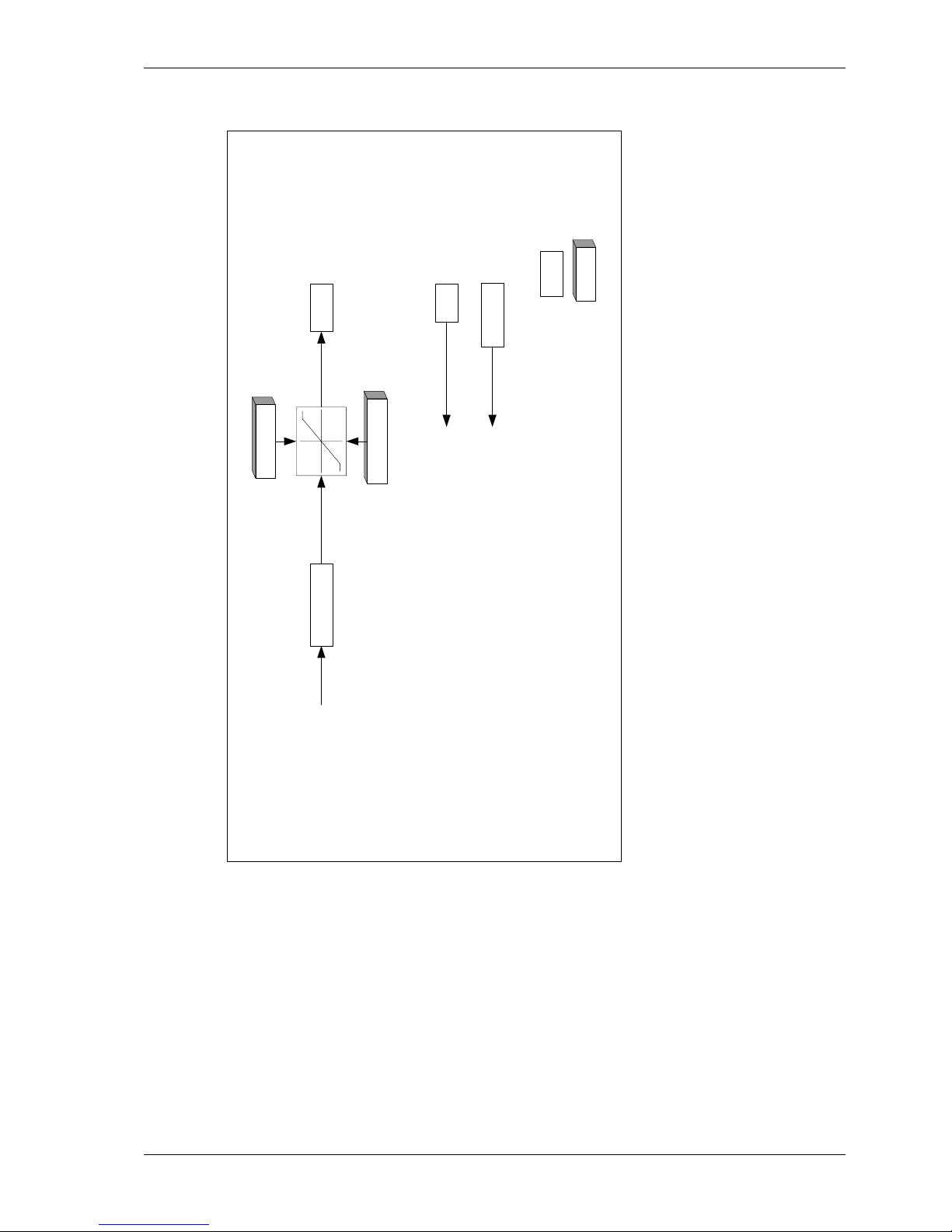
Danaher Motion 05/2008 Advanced Configuration
S200-VTS Product Manual 81
8.3 SynqNet Drive Torque Control Block Diagram
xxxx
NV Setup
Parameter
ILmtMinus
ILmtPlus
SynqNet Master
Current Command
19336 Cnts = Ipeak
Arms
+=CW
xxxx
Variable
Clamp
On
S200 SynqNet Torque Mode
ICmd
+=CW
Net
Torque
Command
Command
Measured
Motor Position
Position Feedback to SynqNet
Master 24 bits/Rev
PosFB
IFB
Current Feedback
9668 Cnts = Ipeak on MoScope
Measured
Motor Current

Advanced Configuration 05/2008 Danaher Motion
82 S200-VTS Product Manual
8.4 SynqNet Drive Velocity Control Block Diagram
xxxx
NV Setup
Parameter
Reset Hold
Velocity Loop
Integrator
2 * .
s
ILmtMinus
ILmtPlus
SynqNet Master
Velocity
Command
+
-
Net Drive
Enable
xxxx
Variable
Measured
Feedback
Velocity Feedback
Rad/sec
Clamp
On
2 Pole
Low Pass
Filter
ARF0 ARF1
+
+
VelErr
S200 SynqNet Velocity Mode
ICmdKVP
KVI
Net
Torque
Command
VelFB
Measured
Motor Position
Position Feedback to SynqNet
Master 24 bits/Rev
PosFB
IFB
Current Feedback
9668 Cnts = Ipeak on MoScope
Measured
Motor Current
+
ICmdFF
Command
SynqNet Master
Current Feed
Forward
19336 = Ipeak
0.058517
Rad/sec
+
Cnts

Danaher Motion 05/2008 Advanced Configuration
S200-VTS Product Manual 83
8.5 Parameters and Variables
Setup parameter values control the operation and configuration of an S200 and read only
variables give status information about the present operation of the drive. The below defines
the three types of parameters and variables.
NV Parameter: A type of variable stored in the non-volatile (NV) permanent memory on
the drive. See
NV Parameters for a complete list and descriptions.
Status Variable: Gives information about the present state of the drive. Most of these
variables are Read-Only, meaning that you cannot directly change them; their value is
controlled by the drive itself, for example, measured shaft speed. See
Status and Control
Variables for a complete list and descriptions.
Control Variable: A variable that controls a particular function on the drive. Control
Variables are volatile (erased when power is removed) and are initialized at fixed default values
every time that the drive is turned on. See
Status and Control Variables for a complete list and
descriptions.
The next section gives more details on the memory structure of the drive and how values are
initialized. The succeeding two sections give detailed lists and descriptions of NV Parameters
and Status, Control Variables respectively. The functionality of the drive may be updated from
time to time, which may add to these lists.
8.5.1 Parameter and Variable Storage
The S200 has two types of memory: non-volatile memory and RAM. S200 non-volatile memory
(NV memory) is similar to disk memory in a personal computer in that it can be written to and
read from and maintains its settings without power. The S200 memory RAM is temporary
memory. When control power is applied, all NV parameter values are automatically copied from
NV memory into S200 RAM memory. The S200 operates out of temporary memory; that is the
temporary memory parameter values set the S200 configuration and adjustments.
S200 Tools configuration software changes S200 settings, which include both parameters and
variables. In the Offline branches of S200Tools configuration software, changes made to a
setting are made only in the PC S200Tools memory on the PC. Clicking the
Download Drive
button sends the values to the drive’s temporary memory. Clicking the
Download NV button
sends the values to the drive’s NV permanent memory. In the latter case the drive’s control
power must be cycled to get the drive to load the values into active use. When downloading or
uploading to the S200 from S200Tools software, all drive settings are copied. It is not possible
to upload or download only one parameter or variable.
In the online branch of S200Tools, the
Drive Setup screen of S200Tools operates differently
than in offline. Under the Drive Setup screen, any change to a parameter is automatically
communicated to the drive's temporary memory. Once all the parameters are set you should
use the File menu to do a file save on the PC to save the drive configuration (*.S2C). If a drive
is connected, you can click the
Download Drive button to send the parameters into the drive.
In the online section of S200Tools the
Status screen allows a custom selection of NV
Parameters and variables to be selected. This screen is useful for interactively making setup
changes and to view drive status. When changes are made to an NV Parameter or a Variable
in this screen, the value in the S200 Tools PC memory is automatically copied to the S200
RAM memory for that particular parameter. Clicking
NV Save on the Status screen uploads the
current state of the drive temporary RAM and downloads all these settings to the S200 nonvolatile memory. This step should be done before power cycling the drive control power and
losing the drive setup changes.
8.5.2 Model Dependent Scale Factors
The Model Dependent Scale Factors are used to calculate limits for some of the drive
parameters. The following table lists the model dependent scale factors.
Model Dependent Scale Factors
Model User DIpeak ARMS VBusScale R elative x Description
S20260 4.5 1 240 VAC 4.5 ARMS peak
S20360 9 1 240 VAC 9 ARMS peak
S20660 18 1 240 VAC 18 ARMS peak
S20330 9 0.25 90 VDC 9 ARMS peak
S20630 18 0.25 90 VDC 18 ARMS peak

Advanced Configuration 05/2008 Danaher Motion
84 S200-VTS Product Manual
8.5.3 Read/Write NV Parameters
ARF0 1.518 – 96382 Hz
ARF1 1.518 – 96382 Hz
ARF0 and ARF1 set the break frequency in Hz for the two single-pole anti-resonance low pass
filters in the forward path of the velocity loop. They are used to help accommodate mechanical
resonance in the system introduced by the load connected to the motor. See the
Base Drive
Torque/Velocity Control Block Diagram for more information.
AuxFBDivisor 1 to 2,147,483,647 (Option Card Only)
Supported over SynqNet.
This parameter is the divisor used to scale the raw incremental encoder counts or the Sin-Cos
encoder interpolated counts from the Aux Feedback interface to the Aux position word. If the
Aux Feedback device is used only for controller feedback then this parameter may be set to
any value convenient for the application. If the Aux Feedback device is used to commutate the
motor then it must be set to a specific value. For rotary motor commutation, this scaling
converts the Aux Feedback position word to a word with 24 bits per revolution. For linear motor
commutation, it converts to 24 bits per motor magnetic pole pitch distance. The table below lists
a number of commonly desired settings for AuxFBDivisor.
Incremental (A quad B) encoder
No motor commutation, 1 encoder
quadrature count = 1 Aux Feedback count:
AuxFBDivisor = 2
24
= 16,777,216
Commutating a rotary motor or 24 bits per
revolution:
AuxFBDivisor = number of quadrature
counts per mechanical revolution
Commutating a linear motor or 24 bits per
magnetic pole pitch:
AuxFBDivisor = number of quadrature
counts per magnetic pole pitch
1 Vp-p Sin-Cos
No motor commutation, 1 interpolation lsb =
1 Aux Feedback count or 65536 counts/SinCos cyle:
AuxFBDivisor = 2
8
= 256
Commutating a rotary motor or 24 bits per
revolution:
AuxFBDivisor = number of Sin-Cos cycles
per mechanical revolution
Commutating a linear motor or 24 bits per
magnetic pole pitch:
AuxFBDivisor = number of Sin-Cos cycles
per magnetic pole pitch
AuxFBType Type (Option Card Only)
Supported over SynqNet.
This parameter selects the type of feedback wired to the AuxFB connector. It is a combination
of the following single bit parameters:
AFBHallDis, AFBDivisorSrc, AFBEnDatEnb, and AFBFBSrc.
The following table defines the state of these parameters for each supported feedback device.
Type AFBHallDis AFBEnDatEnb AFBDivisorSrc AFBFBSrc
Incremental A Quad B Disable Disable AuxFBDivisor AQB
Incremental A Quad B
with Halls
Enable Disable AuxFBDivisor AQB
1 Vp-p Sin-Cos
Incremental
Disable Disable AuxFBDivisor SCD
1 Vp-p Sin-Cos Inc. with
Halls
Enable Disable AuxFBDivisor SCD
EnDat 2.1 Disable Enable AuxPPR SCD
EnDat 2.1 Linear Disable Enable AuxFBDivisor SCD

Danaher Motion 05/2008 Advanced Configuration
S200-VTS Product Manual 85
See AuxFBDivisor to complete the setup of the Aux Feedback interface.
Note: Many EnDat 2.2 devices can be wired to the J14 AuxFB Connector as long as the 1 Vp-p
Sin-Cos analog signals are also wired and the device will run in EnDat 2.1 compatibility mode.
Power up initialization of absolute position will work.
BatFDis Enable/Disable
This parameter enables or disables the Battery Low fault. The Battery input on the command
I/O connector is an optional feature and is not required for proper operation of the drive. It is
only required if the battery backup of the multi-turn information is required from the SFD. If the
feedback device is not an SFD, then the battery does nothing.
0 - Enable Battery Fault
1 - Disable Battery Fault
CmdF0 1.518 – 93254 Hz
CmdF0 sets the break frequency in Hz for two cascaded single pole low pass filters on the
hardware command input. There are two ranges of values for CmdF0; from 2915 to 24873 Hz
cannot be set. The lower range is the active range suggested for velocity control and the upper
range is used to effectively turn the filter off for velocity control or for use with torque/current
control. This parameter is particularly useful when CmdSrc selects the PWM input for the
command source. CmdF0 should be less than the input PWM frequency divided by 10 and
preferably divided by 50 or more. See the
Base Drive Torque/Velocity Control Block Diagram
for more information.
CmdGain See Chart
CmdGain sets the scale factor from the user input on the Command I/O connector (J4) to the
internal servo loop command. CmdGain can be negative or positive, which allows the direction
polarity to be changed. Because the input to the command processing block can be an analog
voltage or a digital duty cycle and the servo loop could be Torque/Current or velocity there are
four combinations of units listed below. See CmdSrc and OpMode for these settings. See
CmdOffset for adding an offset to the command.
Expressed as an equation:
CmdIn = [(User Input) – CmdOffset] * CmdGain
NOTE: The Range of CmdGain is clipped by the value of CmdOffset. The chart below gives
CmdGain units and numerical range assuming that CmdOffset is 0 V/50%.
CmdSrc OpMode CmdGain Units +/- CmdGain Range
Analog Torque / Current ARMS / V ARMS / V
Analog Velocity krpm / V krpm / V
PWM Torque / Current ARMS / % ARMS / %
PWM Velocity krpm / % krpm / %
CmdInNullEnb Enable/Disable
CmdInNullEnb enables or disables the Command In ADC Null function. CmdInNullEnb enabled
allows the user to null the base drive CmdIn ADC by asserting DInp4 for a minimum of one
second. The CmdInNull function will update the variable CmdOffset to null out the DC offset
that is present and the CmdIn ADC at the time DInp4 is asserted. This function updates the
drive NV memory copy of CmdOffset as well.
0 - Enable CmdIn ADC Null function
1 - Disable CmdIn ADC Null function (default setting)
CmdOffset Volts or Percent
CmdOffset is added to the user input on the Command I/O connector J4 to allow any constant
offset present in the source to be cancelled. Because the input to the command processing
block can be an analog voltage or a digital duty cycle, there are two possible units. See
CmdSrc for this setting and CmdGain for scaling the gain of the input command.
Expressed as an equation:
CmdIn = [(User Input) – CmdOffset] * CmdGain

Advanced Configuration 05/2008 Danaher Motion
86 S200-VTS Product Manual
NOTE: The range and resolution of CmdOffset is affected by the value of CmdGain. Its range
covers the entire range of CmdIn.
CmdSrc Analog, PWM CMD, or Command Variable
CmdSrc selects the source of the command. It selects between using the command I/O
connector analog input or PWM CMD digital input or the serial command parameter.
00 - Analog input sets command (default).
01 - PWM input sets command.
10 - Software Command Variable sets command
(analog input Cmd proc).
11 - Software Command Variable sets command
(PWMCMD input Cmd proc).
Command ± DIpeak or ± 18,310 rpm
Not supported over SynqNet.
Sets the value of the command when CmdSrc is set to Command variable as opposed to the
standard Analog or PWM CMD digital hardware inputs. The parameter units depend on
whether the drive is in current or velocity control mode.
When OpMode is set to Position, this
variable is not used.
CommMode SetupS2-2, SFD, 6-Step, Brush
Selects the commutation mode of the drive. The following table describes the different values
for this parameter.
Mode Description
SetupS2-2
DIP switch S2 position 2 selects between 6-step and SFD
commutation, feedback.
SFD Forces the drive to use SFD for feedback.
6-Step Forces the drive to use 6-step.
Brush Forces 6-step commutation with CU, CV, CW = 1 1 0.
CommOff ± 180 Degrees
Offsets the origin for the electrical commutation angle in degrees. Normally set to zero. Nonzero allows matching non-standard motors or systems.
WARNING
In 6-step mode, this parameter must be set to
0 for proper operation. See also CommMode.
Dinp1Pol Invert or Normal
This parameter selects the polarity of the Dinp1. When this parameter is set, the input to the
FPGA is inverted before it is used by the logic. This parameter affects the sense of the enable
I/O input. The following describes the different values for this parameter.
0 - Normal
1 - Invert
Dinp2Pol Invert or Normal
This parameter selects the polarity of the Dinp2. When this parameter is set, the input to the
FPGA is inverted before it is used by the logic. This parameter affects the sense of the
InhibitCW I/O input. The following describes the different values for this parameter.
0 - Normal
1 - Invert
Dinp3Pol Invert or Normal
This parameter selects the polarity of the Dinp3. When this parameter is set, the input to the
FPGA is inverted before it is used by the logic. This parameter affects the sense of the
InhibitCCW I/O input. The following describes the different values for this parameter.
0 - Normal
1 - Invert

Danaher Motion 05/2008 Advanced Configuration
S200-VTS Product Manual 87
Dinp4Pol Invert or Normal
This parameter selects the polarity of the Dinp4. When this parameter is set, the input to the
FPGA is inverted before it is used by the logic. This parameter affects the sense of the MSInp1
I/O input. The following describes the different values for this parameter.
0 - Normal
1 - Invert
DM1Map/DM2Map See Chart
Selects the variable sent to DACMon1, DACMon2 analog output pins on Command I/O
connector J4. The DACMon1/2 output pins have a ± 2.0 V range centered around a 2.5 V bias,
that is the output varies from 0.5 to 4.5 V and is 2.5 V when the selected DAC signal is zero.
NOTE
These DAC outputs are not clamped at maximum analog range.
When the signal reaches maximum analog output, further signal
increases cause it to wrap around to the opposite range
extreme.
DM1Map:
DM2Map:
Parameter Value
Velocity mode
Parameter Value
Torque mode
Definition
VBus 380 * VBusScale
V/V
- Bus voltage.
CmdIn 9155 rpm/V CmdIn 0.8474 *
DIpeak/V
Command.
IFB 0.8474 * DIpeak/V
- Torque current.
VelFB 1144 rpm/V
- Velocity.
I2TFilt0.7152*
(DIpeak
2
) A2/V
- I*I*t filtered value.
VU 812 * VBusScale /V
-
U phase l-n voltage
command.
VqCmd 134.5 *
VbusScale /V
-
Torque voltage
command.
ICMD 0.8474 * DIpeak
ARMS
/V
-
Torque Current
command.
Model Dependent Scale Factors
Model
User
DIpeak
ARMS
VBusScale
Relative x
Description
S20250 4.5 1 240 VAC 4.5 ARMS peak
S20260 4.5 1 240 VAC 4.5 ARMS peak
S20330 9 0.25 90 VDC 9 ARMS peak
S20350 9 1 240 VAC 9 ARMS peak
S20360 9 1 240 VAC 9 ARMS peak
S20630 18 0.25 90 VDC 18 ARMS peak
Parameter Value Definition
VelErr 286 rpm/V
Velocity error.
PosFB 0.25 rev/V
Position big bits.
IdFB 0.8474 * DIpeak ARMS
/V
Non-torque current.
VelFB 2288 rpm/V
Velocity little bits.
VelFB 9155 rpm/V
Velocity big bits.
PosErr 0.0625 Rev/V
Position loop position error.
VdCmd 134.5 * VBusScale/V Quadrature voltage command.
PosFB 244.1e-6 rev/V
Position little bits.

Advanced Configuration 05/2008 Danaher Motion
88 S200-VTS Product Manual
DPoles 0 – 62 Poles (even numbers only)
DPoles sets the drive for the appropriate motor pole count. Typically set to match the motor
pole count. With a feedback device that has multiple cycles per revolution, DPoles is set to
twice the ratio of motor electrical cycles to feedback device electrical cycles per revolution.
Setting DPoles to zero turns electronic commutation off.
Binary 0 = 0 Poles
Binary 1 = 2 Poles
...
Binary 31 = 62 Poles
WARNING
When the
DPoles setting does not match the actual motor pole
count, the motor's operation will be erratic and could be
dangerous.
EncOut 125 to 32768 Lines Via Rotary Switch S1, See Chart
Supported over SynqNet.
Sets the J4-17 to J4-22 emulated encoder output signal’s line count (pulses per revolution)
when the EMU setup rotary switch S1 on the base drive is set to position 0. All other settings for
rotary switch S1 have fixed line counts. (EncOut * 4) = the number of quadrature counts per
revolution.
EncOut Line Count EncOut Line Count
0 500 8 8192
1 512 9 10000
2 1000 10 125
3 1024 11 128
4 2000 12 16384
5 2048 13 20000
6 4096 14
Programmable by
EncOutPPR
Default = 32768
7 5000 15 2500
EncOutPPR 0 to 65535 Lines
Supported over SynqNet.
Sets an arbitrary emulated encoder output line count, also know as pulses per revolution, for
J4-17 to J4-22 outputs. EncOutPPR is only used if the EMU setup switch S1 on the base drive
is set to position 0 and the EncOut NV parameter is set to Programmable.
Note that if EncOutPPR is set to 0 with EncOut set to programmable the J4-17,18 Z-pulse can
be turned off. A SynqNet master application program can then switch EncOut from 14 to an
appropriate other value to enable and disable the Z CH output at the right point in a machine
cycle to be used to trigger an action like a camera. EncOutZOffset can be used to position the
Z CH OUT pulse a the exact desired position.

Danaher Motion 05/2008 Advanced Configuration
S200-VTS Product Manual 89
EncOutZOffset 0 to 65535 Counts
Supported over SynqNet.
EncOutZOffset sets the location of the emulated encoder marker or Z-pulse on the J4-17,18 CH
Z OUT. Base unit (PosFB – EncOutZOffset) is sent to the decoding logic to make the CH Z
OUT so EncOutZOffset allows electronically setting the exact mechanical location for the
emulated Z pulse. See diagram for exact phase of the Z-pulse.
Encoder Phasing for Clockwise Motor Rotation
Z
B
A
PosFB – EncOutZoffset = 0
EnInhibitCCW On or Off
Not supported over SynqNet.
Enables or disables the hardware input that prevents motion in the counter clockwise direction.
When enabled and the hardware input is active, current/torque operation clamps the current
command to 0 or positive/clockwise. With a velocity loop, function enabled, and the hardware
input active, the velocity command is clamped to 0 or positive/clockwise. When both
InhibitCCW and InhibitCW are enabled and both hardware inputs are active, the motion
command is clamped to 0.
0 - OFF
1 - ON
EnInhibitCW On or Off
Not supported over SynqNet.
Enables or disables the hardware input that prevents motion in the clockwise direction. When
enabled and the hardware input is active, current/torque operation clamps the current
command to be 0 or negative/counter clockwise. With a velocity loop, function enabled, and the
hardware input active the velocity command is clamped to be 0 or negative/counter clockwise.
When both InhibitCCW and InhibitCW are enabled and both hardware inputs are active, the
motion command is clamped to 0.
0 - OFF
1 - ON
FBSrc Base Unit Feedback, Option Card Feedback
(Option Card Only)
Supported over SynqNet.
Enables When this bit is set to the Option Card Feedback position, it disables both the SFD and
Hall feedback faults and device interfaces on the base unit. This bit also forces the feedback
position word from the SFD to be zero. The drive is set for sine commutation. In this mode,
writing to the CommOff parameter will change the motor position. This mode is used when an
Option card is attached and the primary feedback device is a Comcoder.
0 - Base Unit feedback device connected.
1 - Option card feedback device connected.
FltDiag Off or Diagnostic Blink Code
FltDiag selects between the DOUT1 (Fault) line being static low for no fault and static high for
drive off and/or faulted, to low for no fault and toggle high low N number of times with the
diagnostic LED fault blink code. The DOUT1 line output is still static high for drive off. See
FaultCode entry for a chart giving the blink counts for each fault.
0 - OFF (default)
1 - Diagnostic Blink Code

Advanced Configuration 05/2008 Danaher Motion
90 S200-VTS Product Manual
FltRstMode Edge or Level
FltrstMode selects how faults are reset by the hardware enable input DInp1 on J4-2. When set
to Level, faults are reset when the drive is in the hardware disabled state. When set to Edge,
faults are reset when DInp1 hardware enable transitions from disabled to enabled.
0 – Edge - Reset faults on DInp1 disabled to enabled transition.
1 – Level - Reset faults on hardware disabled state. (Default)
GearIn 0 – 65535
Not supported over SynqNet.
GearIn is used to scale the input position command when configured as a position controller
(OpMode = Position). This parameter is the divisor used to calculate the revs per step for the
position mode. The formula for calculating motor shaft revs per input count is:
[GearOut/GearIn]/256 = revs per input count
There is 1 input count per step input or per input quadrature count depending on the position
command source selected by PosCmdSrc.
See Also: GearOut and OpMode.
GearOut -32768 – +32767
Not supported over SynqNet.
GearOut is used to scale the input position command when configured as a position controller
(OpMode = Position). This parameter is the dividend used to calculate the revs per step for the
position mode. Typically, this parameter is 256, which allows GearIn to be numerically equal to
the number of steps per rev. GearOut negative reverses the direction of motion for a given
command. The formula for calculating motor shaft revs per input step is:
[GearOut/GearIn]/256 = revs per input step
There is 1 input count per step input or per input quadrature count depending on the position
command source selected by PosCmdSrc.
See Also: GearIn and OpMode.
HSInp1Pol Invert or Normal
This parameter selects the polarity of the HSInp1. When this parameter is set, the input to the
FPGA is inverted before it is used by the logic. This parameter affects the sense of the HSInp1
I/O input.
0 - Normal
1 - Invert
I2TF0 23.16e-6 – 1.470 Hz
I2T0 sets the break frequency in Hz for the I2T filter used to protect the motor coils from
transient thermal overload caused by very high peak currents compared to the motor’s
continuous current capability. I2Tf0 should be set based on the motor coil’s thermal time
constant. However, typical motor data sheets only give the thermal time constant for the entire
motor (coil+back iron+housing) and no data for the coil’s time constant. Since the coil thermal
time constant is much faster than the entire motor time constant I2Tf0 is typically set to
between 4 and 10 times faster than the motor’s bulk thermal time constant published in the
data sheet. Given a desired time constant, set the I2TF0 value to:
I2TF0 = 1/[(2π)*(Motor Thermal Time Constant in sec)]
I2TTrip 0 to 1.19 DIpeak
I2TTrip sets the fault trip level for the I2T fault used to protect the motor coils from transient
thermal overload caused by very high peak currents compared to the motor’s continuous
current capability. It is typically set equal to the motor data sheet continuous current capability
when the motor has no internal thermal shut down sensor. When the motor includes a thermal
sensor I2TTrip is typically set 1.25 times larger than the motor’s continuous current capability
with the motor’s internal thermal sensor providing protection against small overloads.

Danaher Motion 05/2008 Advanced Configuration
S200-VTS Product Manual 91
ILmtPlus/ILmtMinus % of DIpeak
IlmtPlus and ILmtMinus are the clockwise and counter-clockwise current limits, respectively.
They set the maximum allowable torque current command in their respective directions. They
are a percentage of the drive’s peak current rating DIpeak.
ITMode Fault/Foldback
Selects whether the drive faults on too much peak current for too long, i.e., excessive I*t, or
folds the current limits back by clamping them to 67% (IFldBack) or less. If IlmtPlus and
IlmtMinus are set to 67% or less, fold back has no effect. See FoldBack for related information.
KIP 79.226*VBusScale/DIpeak to 19014*VbusScale / DIpeak V / A
KIP sets the proportional gain of the current loops. The bandwidth of the current loop in Hz is =
KIP/(Motor l-l L)/(2π). See the drive specification section for recommended bandwidths.
KPP 0.379 – 93.99 Hz
Not supported over SynqNet.
Sets KPP sets the proportional gain of the position loop in Hz. When OpMode = Position the
net velocity command (VelCmd) in rad/sec is:
VelCmd
= KPP*(2π)*(PosErr) + KVFF/100*d/dt(PosCmd)
KVFF 0 – 199 %
Sets the feed forward gain from the derivative of the position command directly to the velocity
command of the velocity loop and has the units of percent. When OpMode = Position the net
velocity command (VelCmd) in rad/sec is:
VelCmd = KPP*(2π)*(PosErr) + KVFF/100*d/dt(PosCmd)
KVI 0, 0.0238 – 753.9 Hz
KVI adjusts the velocity loop integral compensation. It sets the break out frequency between
predominantly integral compensation and predominantly proportional compensation. Higher
KVI values give higher integral gain and shorter time constants. A value of below 0.19 Hz turns
off KVI. There is no integral compensation only proportional from KVP. See the
Base Drive
Torque/Velocity Control Block Diagram for more information.
KVP 221.0e-6*DIpeak to 25.09*DIpeak ARMS/rad/sec
KVP sets the proportional gain of the velocity loop and has the units of ARMS/rad/sec. The
idealized velocity loop bandwidth in Hz is KVP*KT/JTOT/(2π) where KT is the motor’s torque
constant, JTOT is the total shaft inertia and the units of KT/JTOT should come out to
rad/sec2/ARMS. See the
Base Drive Torque/Velocity Control Block Diagram for more
information.
OpMode Current, Velocity, SetupS2-1, Position
Not supported over SynqNet.
OpMode selects between current/torque, velocity, and position control modes or whether the
SETUP1 hardware switch is used for selecting between current/torque or velocity operating
mode.
OpMode Description
000 Torque/Current Mode
001 Velocity Mode (default)
010 Setup DIP switch S2 position 1 (SetupS2-1 = 0 = Velocity).
011 Position Mode
Note: With SynqNet OpMode is written to by the SynqNet master over the network each
network update period. All SynqNet master versions that support the S200 can work in
Torque/Current mode. Newer SynqNet master versions can optionally be set to run the drive in
Velocity Mode.

Advanced Configuration 05/2008 Danaher Motion
92 S200-VTS Product Manual
PosCmdSrc Step-Dir, AQuadB
Not supported over SynqNet.
PosCmdSrc selects the source of the position command. It selects between using Command
I/O connector J4 optically isolated inputs for Step-Dir and the emulated encoder port used as
an A quad B differential input. J4-10,11 and J4-5 for Step-Dir and J4-19,20 and J4-21,22 for A
quad B inputs. See the
Base Drive Torque/Velocity Control Block Diagram for more information.
0 - AQuadB
1 - Step-Dir (default)
PosErrorMax 0 to 255.996 Rev
Not supported over SynqNet.
PosErrorMax sets the following error limit. When
|(commanded position) – (PosFB)| > PosErrorMax
The drive will fault with a following error fault. The following error fault, and thus PosErrorMax,
are only active when OpMode is Position. Default value is maximum value.
SelSFDParam SFD or Drive
Determines whether the SFD motor parameters or drive setup values are used for the following
parameters:
KVP
Velocity loop proportional gain.
KIP
Current loop proportional gain.
DPoles
Drive poles.
I2TF0
Response speed for motor transient thermal protection.
I2TTrip
Fault trip level for motor transient thermal protection.
ILmtPlus
Sets the drive maximum Iout based on motor I
PEAK.
ILmtMinus
Sets the drive maximum Iout based on motor I
PEAK.
SFDSpan Span or No Span
Sets how the drive handles single sample communication errors with the SFD. Span
interpolates SFD feedback position for isolated single sample communications errors. No Span
faults the drive on any SFD communication error. Recommended (default) setting is Span.
0 - No Span
1 - Span
SWClrFault Not Clear or Clear
This parameter will clear the fault logic.
0 - Not Clear (default)
1 - Clear

Danaher Motion 05/2008 Advanced Configuration
S200-VTS Product Manual 93
8.5.4 Status And Control Variables
AuxFBComAng +180° to -180° (Option Card Only)
Supported over SynqNet.
This register is the value of the commutation position from the AFB interface. It is used to
generate the commutation angle in the drive.
AuxFBEnDatFlt Fault, No Fault (Option Card Only)
Supported over SynqNet.
This bit indicates that the Aux Feedback interface encountered an error when trying to read
data from an EnDat device. Sources of error are:
1 - EnDat device recover timeout from last transaction.
2 - EnDat device calculation timeout.
3 - EnDat CRC fault.
AuxFBHallFlt Fault, No Fault (Option Card Only)
Supported over SynqNet.
This bit indicates the AuxFB Halls are in an illegal state of either all ones or zeros.
0 - No Fault
1 - Fault
AuxFBPTCFlt Fault, No Fault (Option Card Only)
Supported over SynqNet.
This bit indicates the AuxFB PTC has generated a fault.
0 - No Fault
1 - Fault
AuxFBSCDFlt Fault, No Fault (Option Card Only)
Supported over SynqNet.
This bit indicates that the amplitude of the sum of the sine and cosine signals is not with in +/30% of the nominal 1.0 Vp-p.
0 - No Fault, amplitude in range.
1 - Fault, amplitude not with ±30%.
CmdIn (-DIpeak to +Dipeak) or (–18,310 to +18,310 rpm)
CmdIn is the value of the output of the command processing block. This variable's units depend
on whether the drive is in current or velocity control mode. See OpMode for control mode
information.
DInp1 Inactive, Active
Indicates the state of the drive’s enable input on the Command I/O connector (J4).
0 - Active state, current flows in opto isolator input diode.
1 - Inactive state, no current flow.
DInp2 Inactive, Active
For SynqNet, see mpiMotorGeneralIn.
Indicates the state of the hardware input DINP2 on the Command I/O connector (J4).
0 - Active state, current flows in opto isolator input diode.
1 - Inactive state, no current flow.
DInp3 Inactive, Active
Indicates the state of the hardware input DINP3 on the Command I/O connector (J4).
0 - Active state, current flows in opto isolator input diode.
1 - Inactive state, no current flow.
DInp4 Inactive, Active
Indicates the state of the hardware input DInP4 on the Command I/O connector (J4). For
OpMode = Position, PosCmdSrc = Step-Dir this input is the Direction input. In the inactive state,
no LED current, with positive GearOut PosCmd increments with each Step input edge, i.e. the
motor moves clockwise.
0 - Active state, current flows in opto isolator input diode.
1 - Inactive state, no current flow.

Advanced Configuration 05/2008 Danaher Motion
94 S200-VTS Product Manual
DriveOK Fault , No Fault
Drive fault status indicator. This signal is actually the inverse of the FAULT/ DOUT1 output of
the drive on the Command I/O connector (J4). Current flows through DOUT1 when DriveOK is
active or logic one.
0 - Drive fault, see FaultCode.
1 - Drive not faulted.
EMUAI 0, 1
This variable indicates the state of the emulated encoder channel A pin on the Command I/O
connector (J4).
0 - Input CH A OUT– more positive then CH A OUT+.
1 - Input CH A OUT+ more positive then CH A OUT–.
EMUBI 0, 1
This variable indicates the state of the emulated encoder channel B pin on the Command I/O
connector (J4).
0 - Input CH B OUT– more positive then CH B OUT+.
1 - Input CH B OUT+ more positive then CH B OUT–.
Enabled Off, On
This variable indicates the enable state of the drive power stage. This signal is the inverse of
the active on RUN/DOUT2 output of the drive on the Command I/O connector (J4). Current
flows through DOUT2 when Enabled is active or logic one.
0 - Drive disabled power stage OFF.
1 - Drive enabled power stage ON.
EnDatDistMT 0 to 65535
Supported over SynqNet.
If an EnDat 2.1/2.2 encoder is present, this variable holds the number of distinguishable multi-
turns a rotary encoder can resolve.
EnDatPPR 0 to 232 - 1
Supported over SynqNet.
If an EnDat 2.1/2.2 encoder is present, this variable holds the number of signal periods per
revolution for a rotary encoder or signal period length in nm (0.001um) for linear encoders.
ExtFaults Status Value
This variable gives the extended fault status of the drive. Each bit represents an individual fault
that is logically OR-ed with other faults. Note that this variable remembers its last active value
and can be used as a one deep fault log.
Code Extended fault Code Extended fault
1 SFD UART parity error 9 Drive under temperature
2 SFD UART overrun error 10 Drive short circuit
3 SFD UART framing error 11 Drive output over current
4 SFD frame timeout 12 Option card read timeout
5 SFD transfer incomplete 13 Option card watchdog timeout
6 SFD CRC error(s) 14 Step size overflow
7 SFD Motor Data timeout 15 Position error overflow
8 Drive over temperature 16 AuxFB Fault

Danaher Motion 05/2008 Advanced Configuration
S200-VTS Product Manual 95
FaultCode Status Value
This variable gives the fault status of the drive. The below table lists the possible fault states
and gives the number of blinks that the drive’s front panel Status LED will blink to indicate the
fault. See also ExtFaults for further specifics on a given fault.
Blink
Count
Status
Blink
Count
Status
1 Not Assigned 11 Hall Fault
2 Motor Over Temp 12 SFD Configuration Error
3 Drive Over/Under Temp 13 SFD Short
4 Drive I*t Too High 14 SFD Motor Data Error
5 Motor I*I*t Too High 15 SFD Sensor Failure
6 Optional Battery low 16 SFD UART Error
7 Bus Over Voltage 17 SFD Communication Error
8 Bus Under Voltage 18
Option card Watch Dog
timeout
9 Motor l-l or l-n Short 19 Position error too large
10 Output Over Current 20 Open Card Fault
FoldBack Normal, Foldback
Indicates whether the drive is actively folding back the peak current limits because of excessive
I*t. ITMode can be set to fault the drive on either excessive I*t or fold back.
0 - Not in fold back/Not asserting I*t fault.
1 - Fold back/I*t fault.
HallInp 0-7 Decimal
This variable reads back the state of the Hall inputs to the drive on the drive feedback
connector.
Input
CW
Input
CU
Input
CV
HallInp
Value
1 1 1 7
1 0 1 6
1 1 0 5
1 0 0 4
0 1 1 3
0 0 1 2
0 1 0 1
Input Bit
Description
IN8 Hall A
IN9 Hall B
IN10 Hall C
0 0 0 0
HSInp1 Inactive, Active
Indicates the state of the hardware input HSInp+, HSInp- on the Command I/O connector (J4).
For OpMode = Position, PosCmdSrc = Step-Dir this input is the Step input. Input transitions
from LED current to no LED current yields a step count while input transitions from no LED
current to LED current yields no action.
0 - Active state, current flows in opto isolator input diode.
1 - Inactive state, no current flow.
HSOT -50º C to 137.6º C
Read only variable HSOT is the temperature at which the drive will generate a Heat Sink over
temperature fault. Comparing HSOT minus ambient temp to HSTemp minus ambient temp can
give an indication of the amount of head room from thermal overload that the drive has during
normal operation.
HSTemp -41.1º C to 125.8º C
HSTemp reads back the heat sink temperature. HSTemp determines how close the drive is to
thermal shut down by comparing the temperature rise above ambient to the potential rise above
ambient at the drive over temperature fault trip, which can be read as HSOT.

Advanced Configuration 05/2008 Danaher Motion
96 S200-VTS Product Manual
IFB, IdFB -DIpeak to +DIpeak
These variables read back the torque (IFB) and non-torque (IdFB) derated current values.
IFB - Motor torque current.
IdFB - Motor non-torque current.
LogicVer 0 - 15 Decimal
LogicVer gives the version number of the drive logic as a 4-bit unsigned integer. Versions are
assigned sequentially and if necessary, the numbers wrap around (if there are more than 16
versions). Primarily indicates control logic hardware revisions. See variable VerLW for the
control logic version.
Model 0 - 31 Decimal
Model is the base unit identity code for the drive. The only codes defined are in the chart below.
Other codes are configuration errors.
Base Model
S20260 240 VAC 4.5 ARMS
S20360 240 VAC 9 ARMS
S20660 240 VAC 18 ARMS
S21260 240 VAC 30 ARMS
S22460 240 VAC 48 ARMS
S20330 90 VDC 9 ARMS
S20630 90 VDC 18 ARMS
MTemp 0 - 864,870 Ohms
This variable reads back the motor temperature A/D value from the SFD. The value is read
back as the thermal sensor resistance. Using the motor thermal sensor specification this value
can then be converted to a winding temperature.
PosFBMTrn -2048 to +2047 Turns
This variable reads back an instantaneous sample of the shaft position multi-turn from the SFD
feedback port (J3).
PosFB 0 to 65535.9961 Counts
This variable reads back an instantaneous sample of the shaft position within one rev. There
are 24 bits within one rev, but the displayed value is scaled for 65536 counts per rev (i.e. bits
17 through 24 show up as a fractional count after the decimal point). See PosFBMtrn for
integral revolutions.
PWMLo Base, Half Base
Indicates whether the drive has switched to half base PWM frequency. The drive switches to
half base PWM frequency; when the measured motor current is above 0.53 * DIpeak and the
electrical commutation frequency is less than 2.9 Hz. The PWM frequency returns to base if the
measured motor current reduces below 0.32 * DIpeak or the drive speeds up beyond 4.77 Hz
commutation electrical frequency.
0 - Drive uses base PWM frequency.
1 - Drive uses half base PWM frequency
SetupS1 0-9
This variable reads back the state of the rotary user setup switch S1 that determines the line
count of the emulated encoder EMUA and EMUB outputs with SFD feedback or the current
loop proportional gain KIP for 6-step feedback. See Configuring with SFD Feedback.
SetupS2 0-15 decimal
This variable reads back the state of the 4 position DIP setup switch S2 on the drive. Switch
position #1 is LSB.
Open (high)
Closed (low)

Danaher Motion 05/2008 Advanced Configuration
S200-VTS Product Manual 97
SFDExtFaults Status Value
This variable gives the detailed fault code of the SFD.
FaultCode Status
000 No Fault
001 Sensor Error
010 No Fault
011 Multi-turn Fault
100 No Fault
101 No Fault
110 No Fault
111 No Fault
SixStep SFD, 6-Step
This variable indicates whether the drive is in 6-step or sinusoidal current control.
SWEnable Disable, Enable
Serial communications channel motor power enable. Both the hardware enable input on the
command I/O connector and SWEnable must be active for power to flow to the motor. Base
units have SWEnable active at power up. This variable is provided for convenience when
working with a PC set utility.
0 - Disables drive.
1 - Enable set by state of hardware enable input (default).
VBus 0 to 523 volts : AC Input Drives
0 to 131 volts : DC Input Drives
This variable reads back an instantaneous sample of the voltage of the bus supplying power to
the motor.
VelFB –18,310 rpm to +18,310 rpm
This variable reads back an instantaneous sample of the shaft velocity feedback. It has a
resolution of 0.5588 rpm. When measuring speed, use Velocity for least noise and maximum
accuracy.
Velocity –18,310 rpm to +18,310 rpm
This variable reads back a filtered version of the shaft velocity feedback. It has the same units
as VelFB, but it is much more precise for careful measurements of shaft speed because the
filtering greatly lowers noise. To implement the filtered velocity value the drive subtracts two
consecutive PosFB values sampled at a 26.21 mSec sample period which corresponds to a
38.15 Hz sample rate. This filter is equivalent to adding 512 consecutive samples of VelFB and
dividing by 512.
VerLW 0.0a to 255.9z
VerLW gives the version number of the drives logicware as three integer bytes.
This manual documents VerLW 3.0A and newer.

SynqNet Configuration 05/2008 Danaher Motion
98 S200-VTS Product Manual
9 SYNQNET CONFIGURATION
For S200 Series drives that support SynqNet, the following sections explain proper drive
configuration.
9.1 Drive FPGA Table
Node Type Option Valid FPGAs
0x00030030 0x00000000 0xC0FE0036
For more information about FPGAs, visit Motion Engineering, Inc.’s Technical Support site.
(
http://support.motioneng.com)
Go to Hardware -> Drives -> FPGA Images
Parameter Specification
Node Type 0x00000000
Option 0x00000000
FPGA 0xC0FE0036
Motor Count 1
Drive Count 0
Secondary Encoder Count 1
SqNode Digital Out Count 0
SqNode Digital In Count 0
SqNode Analog Out Count 0
SqNode Analog In Count 0
Parameter Motor0
Capture Count 1
Probe Count 1
Pulse Count 0
Dedicated In 0 – Amp Fault 1
Dedicated In 1 – Brake Applied 0
Dedicated In 2 – Home 1
Dedicated In 3 – Limit HW Pos 1
Dedicated In 4 – Limit HW Neg 1
Dedicated In 5 – Index Primary 1
Dedicated In 6 – Feedback Fault 1
Dedicated In 7 – Captured 0
Dedicated In 8 – Hall A 1
Dedicated In 9 – Hall B 1
Dedicated In 10 – Hall C 1
Dedicated In 11 – Amp Active 1
Dedicated In 12 – Index Secondary 1
Dedicated In 13 – Warning 1
Dedicated In 14 – Drive Status 9 1
Dedicated In 15 – Drive Status 10 0
Dedicated Out 0 – Amp Enable 1
Dedicated Out 0 – Brake Release 0

Danaher Motion 05/2008 SynqNet Configuration
S200-VTS Product Manual 99
Motor
General
Purpose I/O Bit
Name Valid Configurations
0 0 RS422 IN 0 Input
0 1 RS422 IN 1 Input
0 2 RS422 IN 2 Input
0 3 RS422 IN 3 Input
0 4 RH 1 Input
0 5 RH 2 Input
0 6 RH 3 Input
0 7 PS OK Input
0 8 IO SHORT Input
0 9 DINP2 Input
0 10 DINP3 Input
0 11 DINP4 Input
0 12 HSINP1 Input
9.2 Drive Monitor
9.2.1 Drive Monitor Table
/* kollmorgen_s200.h */
/*
* Drive Monitor Table
*/
typedef enum {
S200MonitorAddressCMD_IN = 0x3938, /* Value of the output of the command processor
block */
S200MonitorAddressHS_TEMP = 0x8726, /* Heat sink temperateure value */
S200MonitorAddressIFB = 0x4544, /* Torque derotated current value */
S200MonitorAddressIDFB = 0x4746, /* Non-torque derotated current value */
S200MonitorAddressM_TEMP = 0x8700, /* Motor temperature A/D value frm the SFD */
S200MonitorAddressPOS_MTRN = 0x5756, /* Multi turn feedback data */
S200MonitorAddressPOS_FB_LSBS = 0x2E2D, /* Lower 16 bits of the feedback */
S200MonitorAddressPOS_FB_MSBS = 0x872F, /* Upper 8 bits of the feedback */
S200MonitorAddressVBUS = 0x3736, /* Motor power voltage */
S200MonitorAddressVEL_FB = 0x1D1C /* Shaft velocity feedback */
} S200MonitorAddress;

SynqNet Configuration 05/2008 Danaher Motion
100 S200-VTS Product Manual
9.2.2 Monitoring Real-time Data from Drive
Some data from the drive is not part of the standard MEI I/O. However, it can be monitored in
real-time from the drive. For more information on how to monitor real-time data from the drive,
see Drive Monitor.
List of real-time monitor fields. This is a partial list of supported fields. Consult your drive
manual for a complete list.
• CmdIn
• HSTemp
• IFB
• IdFb
• MTemp
• Pos_MTrn (PosFbMTrn)
• PosFbLSBS (PosFb)
• PosFbMSBS (PosFb)
• VBus
• VelFB
9.3 Accessing Drive Parameters over SynqNet
9.3.1 Introduction
The drive's functionality is designed to use various drive parameters and instructions, which are
communicated over SynqNet. Some parameters have read-only access, whereas other
parameters may have read/write access. The parameters can be stored in non-volatile memory
on the drive and are used on each power-up cycle.
Examples of read-only drive parameters are:
• drive command value (CMD_IN)
• drive model number (MODEL)
• drive bus voltage (V_BUS)
Examples of read/write drive parameters are:
• commutation offset value (COMM_OFF)
• proportional gain of the current loop (KIP)
• motor pole count (D_POLES)
Drives are shipped from the factory with motor parameters set to zero and application
parameters set to their default values.
Parameters are identified by their
command string and index. The index is used when
accessing a parameter over SynqNet. Drive parameters are implemented for particular drive
models and firmware versions.
NOTE: Supported parameters for a drive may be different, depending on the version of
firmware.
The MPI library contains a general drive parameter interface that is able to handle any set of
drive parameters, independent of the MPI library version. It uses a drive parameter map file to
determine the valid drive parameters. Individual drive parameters can be set (or read) using
MPI methods or with the sqDriveParam Utility. A list of drive parameters can also be set (or
read) using MPI methods or with the sqDriveConfig Utility.
The following sections describe the syntax of utilities used when accessing parameters. These
utilities are typically executed from a DOS window in the XMP\bin\WinNT directory.
 Loading...