

Encoders
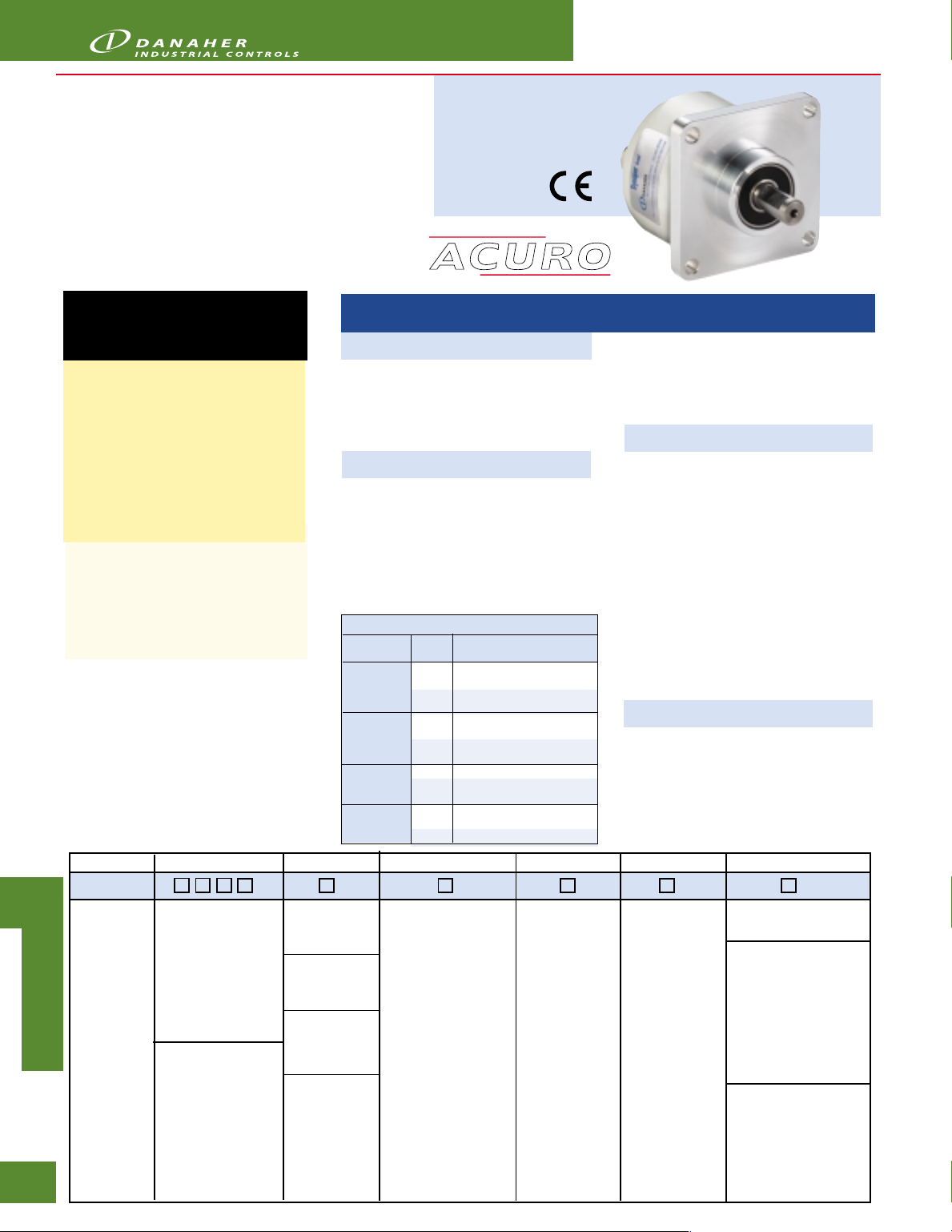
Series AI25 Parallel Interface
• Up to 14 Bit single-turn resolution
• 4096 revolution multi-turn resolution
• Short installation depth
• Safety through self-diagnostics
• Solid shaft and hollow shaft versions
°
• -40
C to +100°C Operating temperature
Dynapar™ brand
APPLICATION/INDUSTRY
The Dynapar brand ACURO Absolute Encoder
offers a modern full-feature design equipped
with Parallel interface.
DESCRIPTION
The Acuro AI25 optical absolute industrial
encoder is available in a single-turn or multiturn version. The multi-turn design is based on
a reliable high-speed gear with optical scanning
and the latest generation of OptoASIC
technology.
The mechanical concept is based on a double
ball bearing design, which is available as a
solid-shaft or hollow-shaft version in common
shaft diameters.
FEATURES AND BENEFITS
• Compact design to save valuable space
• Low power consumption
• Fast delivery of any model variant
• Additional field-bus and point-to-point
interfaces available
Code 1: Model Code 2: Bits Code 3 :Mounting Code 4: Shaft Size Code 5: Protocol Code 6: Electrical Code 7: Connector
A
C
U
R
O
4.
16
AI25
A
AI25
B
Size25
S
Acuro
O
Absolute
L
Encoder
U
T
E
Single-Turn
0010 10 Bit
0012 12 Bit
0013 13 Bit
0014 14 Bit
0360 360 PPR
(Gray excess)
0720 720 PPR
(Gray excess)
Available when Code 6
is 2
Multi-Turn
1212 12 Bit Multi-
Turn, 12 Bit
Single-Turn
Available when
Code 4 is 0 or A
0 Servo*
Available when
Code 4 is 2 or C
1 Clamping*
Available when
Code 4 is 1 or B
2 Square
Available when
Code 4 is 3, 4,
5 or 6
3 Hubshaft
* 58mm Dia.
** 2.5" Square
† 63mm BC
SPECIFICATIONS
STANDARD OPERATING CHARACTERISTICS
Single-turn Resolution: 10, 12, 13, 14 Bit, 360 PPR, 720
PPR
Multi-turn Resolution: 12 bit (only available with 12 bit ST
resolution)
Absolute Accuracy: ± 0.01° mechanical (36 arc-sec.)
Repeatability: ± 0.002° mechanical (7.2 arc-sec.)
Code format: Binary, Gray, Gray Excess
ELECTRICAL
Connection: Cable, Conin Connector,
MS Connector, Cable with Sub-D Connector (MT only)
Supply voltage: 5 VDC -5%/+10%, or 10-30 VDC
Intrinsic current consumption: 200 mA (ST), 300 mA (MT)
Output current: 30 mA per bit, short circuit protected
Frequency response: 500 kHz on single-turn, 1.5m cable*
Alarm output: NPN open collector max 5 mA
Maximum cable length: 100 m
*Data refresh rate: 70µsec is for multi-turn and
single-turn with preset
Control Inputs
Input Logic Function
Direction 1 Ascending code values
Latch 1 Encoder data continuously
Tristate (ST) 1 Outputs active
Tristate (MT) 1 Outputs at high impedence
flange**
w/tether†
Level
when turning clockwise
0 Descending code values
when turning clockwise
changing at output
0 Encoder data stored and
constant at output
0 Outputs at high impedence
(Tristate mode)
(Tristate mode)
0 Outputs active
w/o shaft seal (IP64)
0 6 mm
1 3/8"
2 10 mm
3 3/8" Hub Shaft
4 12 mm Hubshaft
5 1/2" Hubshaft
6 10 mm Hub Shaft
w/ shaft seal (IP67)
A 6 mm
B 3/8"
C 10 mm
0 Parallel
Binary
1 Parallel
Gray
Status LED: Green = OK, Red = Alarm (IP64 only, not
available on connector type J)
Preset Switch: Sets encoder to zero output at present
mechanical position (Multi-turn IP64 only, not available on
connector type J)
Control Inputs: Latch, Direction, Tri-state (see table below)
MECHANICAL
Shaft diameter:
Shaft: 6 mm (Servo Mount), 10 mm (Clamping Mount), 3/
8" (Square Flange Mount)
Hubshaft: 10mm, 12 mm, 3/8", 1/2"
Maximum shaft load:
6 mm shaft: 13 lb axial, 24 lb radial
10 mm shaft: 24 lb axial, 35 lb radial
Maximum shaft speed: 10,000 RPM (continuous), 12,000
RPM (peak)
Starting torque: < 1.4 in-oz
Weight (approx.): 350 g ST, 400 g MT
Shaft tolerance (hubshaft only): +/- 1.5 mm axial, +/- 0.2
mm radial
Flange configurations: Square, Clamp, Servo, Hubshaft
with flexible tether
Bearing life:
10
1 x 10
revolutions at 35% full rated shaft load
9
revolutions at 75% full rated shaft load
1 x 10
8
revolutions at 100% full rated shaft load
1 x 10
ENVIRONMENTAL
Operating Temperature: -40 to 100° C
Storage Temperature: -40 to 100° C
Enclosure Rating: IP64 or IP67
Shock: 1,000 m/s
Vibration: 100 m/s
0 5 VDC
2 10-30 VDC
2
(6 ms)
2
(10 to 2,000 Hz)
0 1.5m axial cable
1 1.5m radial cable
Available when Code 2
is 00XX, 0360 or
0720
6 M23 Conin
17 pin axial CW
7 M23 Conin
17 pin radial CW
J 17 pin MS axial *
K 19 pin Bayonet radial
Available when Code 2
is 1212
A Cable 1.5m radial w/
37 pin sub-D
B Cable 1.5m axial
w/37 pin sub-D
*
Status LED and Preset Switch
features not available with "J"
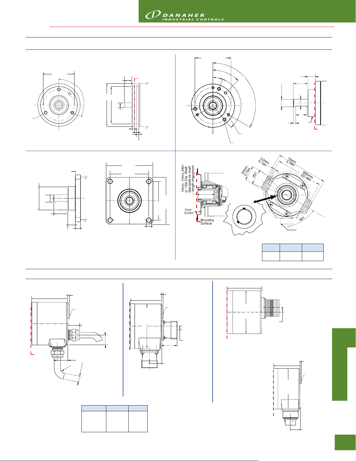
M4x5
0
Servo
Ø31.75mm
1.25in
19.5mm ±0.3
0.77in ±0.01
Ø42 ±0.1mm
1.65±0.004in
3/8in Dia. Shaft
10mm
0.39in
Mounting
Surface
Encoders
Code 3: Mounting
Ø48 ±0.1mm
Ø1.89 ±0.004in
45°
20°
4mm
0.16in
3mm
0.12in
Mounting
Surface
3mm
0.12in
10mm
58mm
2.28in
50mm
1.97in
0.39in
6mm
120°
1
M4x5
1
20
°
M3x5
120
°
Clamping
63.5mm
2.5in
52.4mm
2.06in
Note: two M3 set screws in
colar around hub shaft
(will not mar shaft)
7mm
0.28in
52.4mm
2.06in
Ø5.6mm
0.22in
63.5mm
2.5in
10mm
Diameter
3mm
0.12in
10mm
0.39in
19.27mm
0.76in
9mm
0.35in
15mm
0.59in
Radial Connector
Area (if used). See
Connection Diag.
Ø36mm
Ø1.42in
Mounting
Surface
2
Square Flange
Length (L)
Ø57mm
Ø2.24in
Mounting
Surface
0, 1, A, B
1.5M Cable
2.1mm
0.08in
Location of
Models with IP64
Status LED
sealing: Location of
and Preset Switch
Status LED and
on models with
Preset Switch (multi-
IP64 sealing
turn only)
15mm
0.59in
14.8mm
m
8.5m
0.33in
Ø
Ø
Cables shown in
Axial and Radial
Placement
0.58in
13mm
0.51in
R
Length (L) Mounting Surface to Rear
Mount (Code 3) Single-Turn Multi-Turn
(0) Servo 46.5/1.83 60.2/2.37
(1) Clamping 45.5/1.79 59.2/2.33
(2) Square Flng 45.5/1.79 59.2/2.33
(3) Hubshaft 49.9/1.96 67.1/2.64
Code 7: Connector
2.1mm
2.24in
0.08in
Location of
Models with IP64
Status LED
sealing: Location of
and Preset Switch
Status LED and
on models with
Preset Switch (multi-
IP64 sealing
turn only)
23mm
0.91in
17.5mm
0.69in
Mounting
Surface
Length (L)
Ø57mm
6, 7
Conin 12/17 Pin Connector
3
Hubshaft w/Tether
9.0mm
0.35in
Connectors
shown in Axial
and Radial
Placement
Hubshaft Shaft Engagement
HubShaft Min. Shaft Max. Shaft
Diameter Length Length
10mm, 3/8" 15mm (0.59") 20mm (0.79")
12mm, 1/2" 18mm (0.71") 20mm (0.79")
Length (L)
Ø57mm
Mounting
Surface
2.24in
17 Pin MS Connector, Axial
9.0mm
0.35in
J
Mounting
Surface
K
19 Pin Bayonet Connector, Axial
Length (L)
2.24in
Ø57mm
2.1mm
0.08in
Location of
Models with IP64
Status LED
sealing: Location of
and Preset Switch
Status LED and
on models with
Preset Switch (multi-
IP64 sealing
turn only)
17.5mm
0.69in
A
A
C
B
U
S
R
O
O
L
U
T
E
4.
17

Encoders
CONNECTOR WIRING
Explanation of Terms
+UB = Outputs at high impedance (Tristate mode)
0 V
+UB2) = Outputs active
0 V = Outputs at high impedance (Tristate-Mode)
+UB
0 V = Encoder data stored and constant at output
+UB
0 V = Descending code value when turning cw
= Not Connected
= Least Significant Bit
= Most Significant Bit
= Data bits for resolution per turn
= Data bits for number of turns
4)
A
C
U
R
O
18
Tristate
Tristate
Latch
Direction
N.C.
LSB
MSB
S0, S1, ...
M0, M1, ...
(Multiturn)
2) Or unattached (floating)
PVC-cable (Singleturn) 9-12 Bit
Color 9 Bit / 360
brn/gry N.C. N.C. S0 (LSB)
red/blu N.C. N.C. S1
vio N.C. S0 (LSB) S2
wht/brn S0 (LSB) S1 S3
wht/grn S1 S2 S4
wht/yel S2 S3 S5
wht/gry S3 S4 S6
wht/pnk S4 S5 S7
wht/blu S5 S6 S8
wht/red S6 S7 S9
wht/blk S7 S8 S10
brn/grn S8 (MSB) S9 (MSB) S11 (MSB)
yel Tristate D0...D8 Tristate D0...D9 Tristate D0.. D11
pnk Latch
grn Direction Direction Direction
blk 0 V 0 V 0 V
red 5/10...30VDC 5/10...30VDC 5/10...30VDC
brn Alarm Alarm Alarm
3) Increments 4) Binary Only
Connector 17pol. (CONIN) 9-12 Bit
Pin 9 Bit / 360
1 S0 (LSB) S0 (LSB) S0 (LSB)
2 S1 S1 S1
A
3 S2 S2 S2
B
4 S3 S3 S3
S
5 S4 S4 S4
O
L
6 S5 S5 S5
U
7 S6 S6 S6
T
8 S7 S7 S7
E
9 S8 (MSB) S8 S8
10 N.C. S9 (MSB) S9
11 N.C. N.C. S10
12 Tristate S0...S8 Tristate S0...S9 S11 (MSB)
13 Latch
14 Direction Direction Direction
15 0 V 0 V 0 V
16 5/10...30VDC 5/10...30VDC 5/10...30VDC
4.
17 Alarm Alarm Alarm
3) Increments 4) Binary Only
Series AI25 Parallel Interface
2)
= Outputs active
2)
= Encoder data continuously changing at output
2)
= Ascending code value when turning cw
3)
4)
3)
10 Bit/720
Latch
10 Bit / 720
4)
Latch
3)
4)
3)
12 Bit
Latch
12 Bit
Latch
4)
4)
Connector 17pol. (CONIN) 13-14 Bit
Pin 13 Bit 14 Bit
1 S12 (MSB) S13 (MSB)
2 S11 S12
3 S10 S11
4 S9 S10
5 S8 S9
6 S7 S8
7 S6 S7
8 S5 S6
9 S4 S5
10 S3 S4
11 S2 S3
12 S1 S2
13 S0 (LSB) S1
14 Direction S0 (LSB)
15 0 V 0 V
16 5/10...30VDC 5/10...30VDC
17 Latch (Binarycode) Latch (Binarycode)
Alarm (Graycode) Alarm (Graycode)
TPE-cable (Multiturn 13-14 Bit) 37 pol. Sub-D
Color Pin
brn 2S0
grn 21 S1
yel 3S2
gry 22 S3
pnk 4S4
vio 23 S5
gry/pnk 5S6
red/blu 24 S7
wht/grn 6S8
brn/grn 25 S9
wht/yel 7 S10
yel/brn 26 S11
wht/gry 8M0
gry/brn 27 M1
wht/pnk 9M2
pnk/brn 28 M3
wht/blu 14 M4
brn/blu 33 M5
wht/red 15 M6
brn/red 34 M7
wht/blk 16 M8
brn/blk 35 M9
gry/grn 17 M10
yel/gry 36 M11
pnk/grn 18 Alarm
yel/pnk 10 Direction
grn/blu 30 Latch
yel/blu 12 Tristate
red 13 10...30 VDC
wht 31 10...30 VDC
blu 10 V
blk 20 0 V

MS style 17 pin connectors
Function
12 Bit 10 Bit Accessory*
Pin 4096 CPR 1024 CPR Color Code 14 BIT 13 BIT
A Vin Red D13 (MSB) D12 (MSB)
B N.C. Violet D12 D11
C
D Direction Orange D10 D9
E S1 N.C. White D9 D8
F S3 S1 White/Brown D8 D7
G S5 S3 White/Orange D7 D6
H S7 S5 White/Green D6 D5
J S8 S6 White/Blue D5 D4
K S9 S7 White/Violet D4 D3
L S11 (MSB) S9 (MSB) White/Black/Brown D3 D2
M GND Black D2 D1
N S4 S2 White/Red D1 D0 (LSB)
P S0 (LSB) N.C. Gray D0 (LSB) Direction
R S2 S0 (LSB) White/Black GND GND
S S6 S4 White/Yellow Latch Latch
T S10 S8 White/Grey Vin Vin
Latch (binary only)
10ft Cable # 107865-0010 NA
Mating Connector: MS 17 pin style
MS3106A-20-29S part # MCN-N8
*This is a mating connector/cable assembly.
Color coding information is provides here for reference
107865
Cable
Green D11 D10
Encoders
PVC-cable (Singleturn 13-14 Bit)
Color 13 Bit 14 Bit
gry/pnk N.C S0 (LSB)
brn/yel S0 (LSB) S1
brn/gry S1 S2
red/blu S2 S3
vio S3 S4
wht/brn S4 S5
wht/grn S5 S6
wht/yel S6 S7
wht/gry S7 S8
wht/pnk S8 S9
wht/blu S9 S10
wht/red S10 S11
wht/blk S11 S12
brn/grn S12 (MSB) S13 (MSB)
yel Tristate S0...S12 Tristate S0...S13
pnk Latch
grn Direction Direction
blk 0 V 0 V
red 5/10...30VDC 5/10...30VDC
brn Alarm Alarm
4) Binary Only
4)
Latch
4)
Bayonet style 19 pin connectors
Pin
Function
14 Bit
16384 CPR
A
S13 (MSB)
B
S12
C
S11
D
S10
E
S9
F
S8
G
S7
H
S6
J
S5
K
S4
L
S3
M
S2
N
S1
P
S0 (LSB)
R
Direction
S
Case
T
GND
U
Latch
V
Vin
10ft Cable # 112077-0010 10ft Cable # 112076-0010 10ft Cable # 110158-0010
112077 Cable
Accessory*
Color Code
White/Black/Brown
White/Grey
White/Violet
White/Blue
White/Green
White/Orange
White/Yellow
White/Red
White/Brown
White/Black
Brown
Blue
White
Grey
Orange
Violet
Black
Green
Red
Mating Connector: 19 pin Bayonet style PT06E-14-19S part # 606219-0001
Function
13 it
8192 CPR
S12
S11
S10
S9
S8
S7
S6
S5
S4
S3
S2
S1
S0 (LSB)
GND
Direction
Case
GND
Latch
Vin
112076 Cable
Accessory*
Color Code
White/Black/Brown
White/Grey
White/Violet
White/Blue
White/Green
White/Orange
White/Yellow
White/Red
White/Brown
White/Black
Blue
White
Grey
Black
Orange
Violet
Yellow
Green
Red
Function
12 Bit 10 Bit
4096 CPR 1024 CPR
S11 (MSB) S9 (MSB
S10 S8
S9 S7
S8 S6
S7 S5
S6 S4
S5 S3
S4 S2
S3 S1
S2 S0 (LSB)
S1 N.C.
S0 (LSB) N.C.
N.C N.C.
GND
Direction
Case
GND
Latch (binary only)
Vin
110158 Cable
Accessory*
Color Code
White/Black/Brown
White/Grey
White/Violet
White/Blue
White/Green
White/Orange
White/Yellow
White/Red
White/Brown
White/Black
White
Grey
Black
Orange
Violet
Yellow
Green
Red
A
A
C
B
U
S
R
O
O
L
U
T
E
*This is a mating connector/cable assembly. Color coding information is provided here for reference
4.
19
 Loading...