

Page 1
HEAVY DUTY
DataA
DataA
DataB
Index
(180° ELEC)
(90° ELEC)
AleadsB,CCW(FromClampEnd)
DATAANDINDEX
Notallcomplementsshown
Ashownforreference
IndexWidth:150°to330°
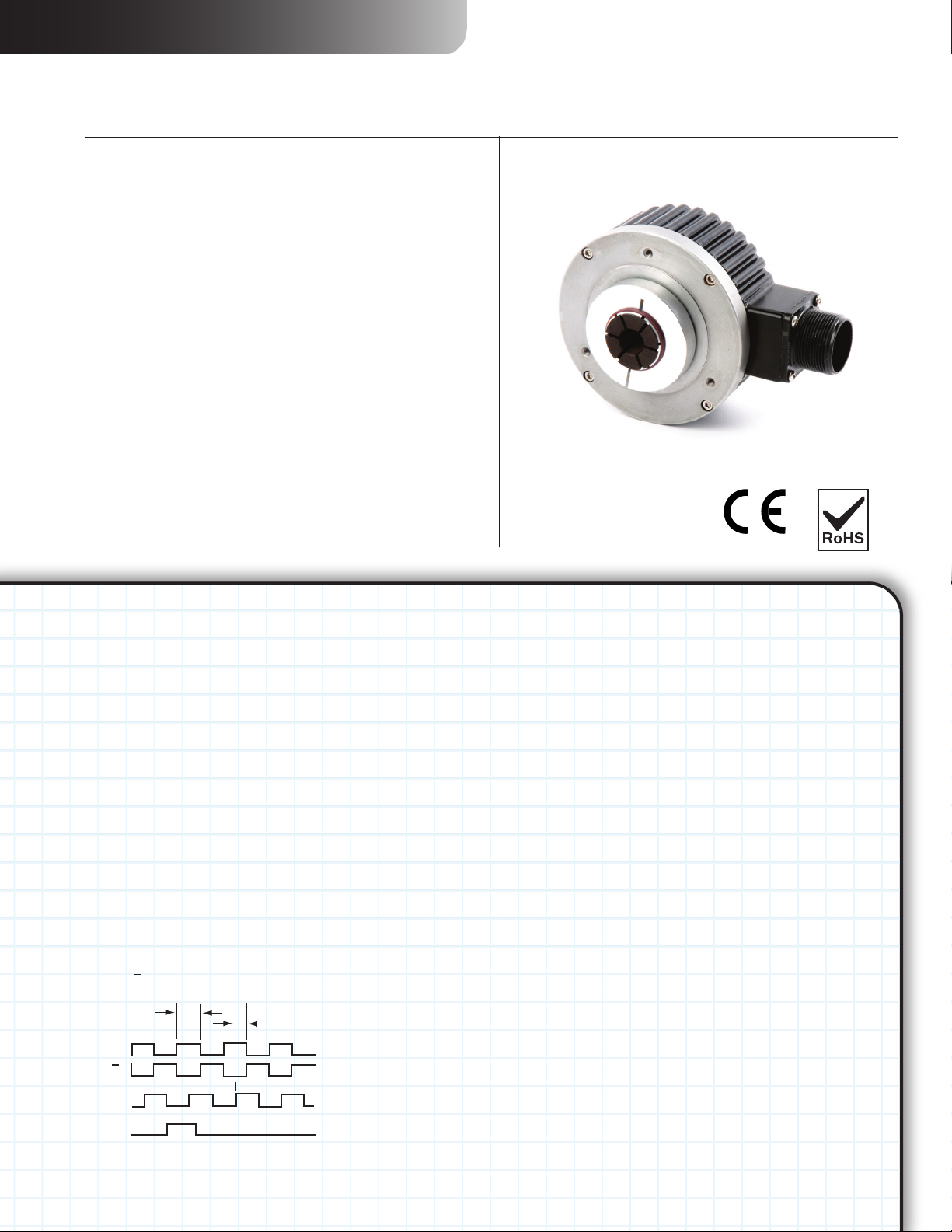
SERIES HSD38
Harsh Duty Optical Encoder
KeyFeatures
• PremierChoiceforVectorMotorOEMs
• UnbreakableCodeDiscupto5000PPR
• Dual-SealedHousing
• Electrically&ThermallyIsolatedHollow
shaft
NorthStar
EN 61326-1
™
brand
SPECIFICATIONS
STANDARD OPERATING CHARACTERISTICS
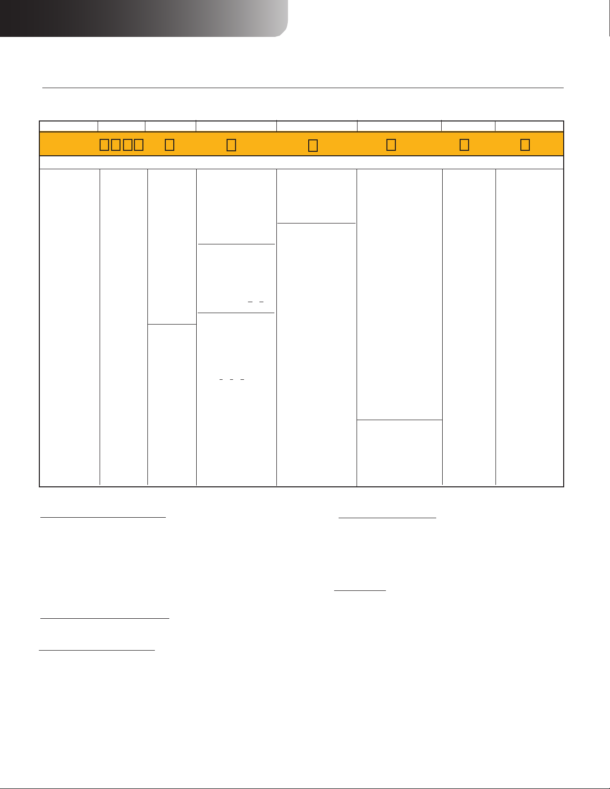
Code: Incremental, Optical
Resolution: 15 to 5000 PPR (pulses/revolution) See
Ordering Information
Format: Two channel quadrature (AB) with optional
Index (Z), and complementary outputs
Phase Sense: A leads B for CCW shaft rotation
viewing the shaft clamp end of the encoder
Quadrature Phasing: For resolutions to
1200 PPR: 90° ± 15° electrical; For resolutions over
1250 PPR: 90° ± 30° electrical
Symmetry:
For resolutions to 1024 PPR: 180° ±18° electrical
For resolutions over 1024 PPR: 180° ±25° electrical
Index: 150° to 330°, Reverse Phasing, A leads
B for CW also available: See Code 7 in Ordering
Information
Waveforms: Squarewave with rise and fall times
less than 1 microsecond into a load capacitance of
1000 pf
ELECTRICAL
Input Power: 5-26VDC. 50 mA max., not including
output loads.
Outputs:
7272 Push-Pull: 40mA, sink or source
7272 Differential Line Driver: 40 mA, sink or source
7273 Open Collector: 40mA, sink max
Frequency Response: 125 kHz (data & index)
Noise Immunity:
Electrical Immunity: Reverse polarity and short
circuit protected
Termination: MS Connector; M12 Connector; cable
exit w/seal. See Ordering Information
Mating Connector:
6 Pin MS, Style MS3106A-14S-6S (MCN-N4);
7 Pin MS, Style MS3106A-16S-1S (MCN-N5);
10 Pin MS, Style MS3106A-18-1S (MCN-N6);
10 Pin Bayonet, MS3116-F12-10S (MCN-B1)
12 Pin CW M23 Connector (MCN-C1)
Cable w/ 5 Pin M12 Connector, p/n 112859-xxxx
Cable w/ 8 Pin M12 Connector, p/n 112860-xxxx
Note: “MS” type mating connectors and pre-built cables are
rated NEMA 12. “M12” Cable assemblies are rated IP67
Tested to EN61326-1
MECHANICAL
Bore Diameter: 12mm - 20mm, 1/2” - 1”. Insu-
lated inserts provided for bores under 1 inch
Mounting Configuration: Hollow Bore, direct
mount over shaft with multiple tether options
Bore Tolerance:
1” bore: 1.0005” -0.0000” / +0.0010”
< 1” bore: Nominal -0.000” / +0.002”
Shaft Speed: 6000 RPM Maximum
Mating Shaft Requirments:
Configuration: Keyway alowed, Flat not allowed
Runout: ±0.025” (0.635mm) radial, typical
Endplay: ±0.050” (1.27mm) axial, typical
Length: 1.25”, Minimum, 1.60”, Recommended
Maximum Length (w/ cover on): 2.50” (63.5mm)
Starting Torque: 8 in-oz. maximum (at 25°C)
Running Torque: 5 in-oz. maximum (at 25°C)
Bearings: 61806-ZZ
Housing and Cover: Aluminum
Shaft Material: 6061-T6 Aluminum
Disc Material: Mylar
Weight: 26 ounces, typical
ENVIRONMENTAL
Operating Temperature: -40 to 100°C
Storage temperature: -40 to 100°C
Shock: 50G’s for 11msec duration
Vibration: 5 to 2000Hz @ 20 G’s
Humidity: Up to 98% (non-condensing)
Enclosure Rating: IP67
(Reverse phasing, A leads B for CW also available:
See Code 7 in Ordering Information)
Page 2
HEAVY DUTY
NorthStar
To order, complete the model number with code numbers from the table below:
Code 1: Model
HSD38
HSD38 Size 38
Heavy-duty,
hollowshaft
encoder
Code 2: PPR
0015
0032
0050
0060
0100
0200
0240
0250
0500
0512
0600
1000
1024
1200
2000
2048
3072
4000
4096
5000
Code 3: Bore Size
Electrically
isolated:
6 12mm
9 15 mm
7 1/2”
8 5/8”
A 16mm
C 3/4”
D 20mm
E 7/8”
T 5/8”
Not electrically
isolated:
G 1”
H 1”
™
brand
Stainless
Steel
Collar
Stainless
Steel
Collar
OrderingInformation
Code 4: Format
0 Single Ended,
Undirectional (A)
1 Single Ended,
Bidirectional (AB)
2 Single Ended,
Bidirectional with
Index (ABZ)
Available when Code 5
is 3 or 4 and Code
6 is 1, 2, 4, 6, 7, 8,
9, A, B, C, D, G, J,
K, P, H, L:
3 Differential, Bidi-
rectional ( AA BB)
Available when Code 5
is 3 or 4 and
Code 6 is 2, 3, 4, 7,
8, 9, A, B, C, D, G,
J, K, P, H, L:
4 Differential, Bidi-
rectional with Index
( AA BB ZZ)
Code 5: Output
Ordering Information
0 5-26V in, 5-26V
Open Collector out
(7273)
2 5-26V in, 5-26V
Push-Pull out (7272)
Available when: Code
4 is 3 or 4
3 5-26V in, 5-26V
Differential Line
Driver out (7272)
4 5-26V in, 5V
Differential Line
Driver out (7272)
SERIES HSD38
Code 6: Termination
0 6 pin connector
1 7 pin connector
2 10 pin connector
3 12 pin connector
4 10 pin Bayonet con-
nector
5 6 pin + mating con-
nector
6 7 pin + mating con-
nector
7 10 pin + mating con-
nector
8 10 pin Bayonet +
mating connector
9
12 pin + mating connector
A 18” (.5m) cable
B 36” (1m) cable
C 72” (2m) cable
D 144” (4m) cable
G 13” (.3m) cable
J 8 pin M12 connector
K 18” (.5m) Cable with
10-pin In-Line
Connector
P 1.5 ft (18”) Cable with
10-pin Bulkhead
Connector
Available when:
Code 5 is 0 or 2
H 5 pin M12 connector
L 5 pin M12 connector
w/special pinout
Code 7: Options
0 No Option
1 Internally
Isolated 1”
Bore
2
Reverse
Phasing, No
Bore Isolation
3 Internally
Isolated 1”
Bore, and
Reverse
Phasing
Code 8: Housing
0 Cast Aluminum
Housing, Slotted
Tether Included
6 Cast Aluminum
Housing, No
Tether
C Cast Aluminum
Housing, SinglePoint Tether
Included
(NEMA 4-1/2”
C-Face)
D Same as “0” with
Cover Kit
E Same as “C” with
Cover Kit
K Cast Aluminum
Housing, SinglePoint Tether
Included
(NEMA 8-1/2”
C-Face)
M Swivel-Rod
Tether with Metric
Hardware
N Same as “K” with
Cover Kit
Cable Assemblies with MS Connector*
108594-XXXX 6 Pin MS, Cable Assy. For Use with Single Ended Outputs
108595-XXXX 7 Pin MS, Cable Assy. For Use with Single Ended Outputs
108596-XXXX 7 Pin MS, Cable Assy. For Use with Differential Line Driver w/o Index Outputs
112123-XXXX 6 Pin MS, Cable Assy. For Use with Differential Line Driver w/o Index Outputs
1400635XXXX 10 Pin MS, Cable Assy. For Use with Differential Line Driver with Index Outputs
114448-XXXX 10 Bayonet, Cable Assy. For Use with Differential Line Driver with Index Outputs
109209-XXXX NEMA4 10 pin MS, Cable Assy. For use with Differential Line Driver with
Index Outputs
Cable Assemblies with M23 Connector*
115901-XXXX 12 pin M23, Cable Assy. For Use with Differential Line Driver with Index
Outputs, CW
Cable Assemblies with M12 Connector*
112859-XXXX 5 Pin M12, Cable Assy. For Use with Single Ended Outputs
112860-XXXX 8 Pin M12, Cable Assy. For Use with Single Ended Outputs
112860-XXXX Pin M12, Cable Assy. For Use with Differential Line Driver Outputs
*Note: Standard cable length is 10 feet but may be ordered in any length in 5 foot increments.
For example, for a 20 foot cable, replace XXXX with -0020.
Mating Connectors (no cable)
6 pin, style MS3106A-14S-6S (MCN-N4)
7 pin, style MS3106A-16S-1S (MCN-N5)
10 pin, style MS3106A-18-1S (MCN-N6)
10 pin bayonet, style MS3116-F12-10S (MCN-B1)
12 Pin CW M23 Connector (MCN-C1)
Accessory Kits
114619-0001 Tether Kit, 4.5” C-Face Single Point with 3/8” Bolt
114620-0001 Tether Kit, Slotted with T-Bolts for Standard AC
Motor Fan Covers
114621-0001 Tether Kit, 8.5” C-Face Single Point with 1/2” Bolt
114591-0001 Cover Kit, 56 C-Face
114592-0001 Cover Kit, Fan Cover
114593-0001 Dual Cover Kit, 56 C-Face
114594-0001 Dual Cover Kit, Fan Cover
Page 3
by
4.40
[111.76]
Ø1.60
[40.64]
0.86 [21.84]
S1.000 I.D. COMPLETE LY THRU THE HAFT
FOR 1.000, +000 , -.003 SHAFT
Ø
8-32 x .22 DEEP
ON 3.000 B.C.
2.50 [63.5]
3X
120˚
3X
WITH LOCTITE ON THREADS
10 -32 CLAMP SCREW
TORQUE TO 50 - 55 IN/LBS
0.23 [5.84]
1.77
[44.9]
0.03 [0.76]
0.56
[14.22]
Ø2.06 [52.32]
Ø1.00
[25.4]
PILOT
Ø2.50
[63.5]
Ø3.80
[96.52]
3.20 [81.2]
OPTIONAL CABLE OUTPUT
Cable # 108594-XXXX
Cable # 108595-XXXX
6 Pin Single Ended
7 Pin Single Ended
Cable # 108596-XXXX
7
Pin Dif Line Driver
With Out Index
Pin
E
D
C
B
A
—
F
—
—
—
Wire Color
BRN
ORG
YEL
RED
BLK
—
—
—
—
—
Pin
A
B
C
D
F
G
E
—
—
—
Wire Color
BRN
ORG
YEL
RED
BLK
GRN
—
—
—
—
Pin
A
B
—
D
F
G
—
C
E
—
Wire Color
BRN
ORG
—
RED
BLK
GRN
—
BRN/WHT
ORG/WHT
—
Pin
A
B
C
D
F
G
E
H
I
J
Wire Color
BRN
ORG
YEL
RED
BLK
GRN
—
BRN/WHT
ORG/WHT
YEL/WHT
Cable #115901-XXXX
12 Pin (CW)
5
8
3
12
7
10
9
6
1
4
Pin
BRN
ORN
YEL
RED
—
BLK
—
BRN/WHT
ORN/WHT
YEL/WHT
Wire
Color
Cable Exit
with Seal
Wire Color
GRN
BLU
ORG
RED
BLK
WHT
—
VIO
BRN
YEL
**Cable # 1400635XXXX
**Cable # 109209-XXXX
10 Pin Dif Line Driver with Index
B
___
___
___
Cable # 114448-XXXX
10 Pin Bayonet
Pin
A
B
C
D
F
G
E
H
I
J
Wire Color
BRN
ORG
YEL
RED
BLK
GRN
—
BRN/WHT
ORG/WHT
YEL/WHT
SERIES HSD38
ELECTRICAL CONNECTIONS
6, 7 & 10 Pin MS Connectors and Cables
Connector & mate/accessory cable assembly pin numbers and wire color information is provided here for reference. Models with
direct cable exit carry the color coding as shown in the right hand column.
Encoder
Cable # 108594-XXXX
Function
6 Pin Single Ended
Pin
Sig. A
E
Sig. B
D
Sig. Z*
C
Power +V
B
Com
A
Case
—
N/C-SLD
F
___
Sig. A
—
___
Sig.
B
—
___
—
Sig. Z*
Wire Color
BRN
ORG
YEL
RED
BLK
—
—
—
—
—
Cable # 108595-XXXX
7 Pin Single Ended
Pin
Wire Color
A
BRN
B
ORG
C
YEL
D
RED
F
BLK
G
GRN
E
—
—
—
—
—
—
—
Cable # 108596-XXXX
Pin Dif Line Driver
7
With Out Index
Wire Color
Pin
BRN
A
ORG
B
—
RED
D
BLK
F
GRN
G
—
BRN/WHT
C
ORG/WHT
E
—
**Cable # 1400635XXXX
**Cable # 109209-XXXX
10 Pin Dif Line Driver with Index
Pin
Wire Color
A
B
—
—
—
C
D
F
G
E
H
I
J
BRN
ORG
YEL
RED
BLK
GRN
—
BRN/WHT
ORG/WHT
YEL/WHT
Cable # 114448-XXXX
10 Pin Bayonet
Pin
Wire Color
A
B
C
D
F
G
E
H
I
J
BRN
ORG
YEL
RED
BLK
GRN
—
BRN/WHT
ORG/WHT
YEL/WHT
Cable #115901-XXXX
12 Pin (CW)
Pin
5
8
3
12
10
9
7
6
1
4
Wire
Color
BRN
ORN
YEL
RED
BLK
—
—
BRN/WHT
ORN/WHT
YEL/WHT
Cable Exit
with Seal
Wire Color
GRN
BLU
ORG
RED
BLK
WHT
—
VIO
BRN
YEL
HEAVY DUTY
5 & 8 Pin M12 Accessory Cables when Code 6 = H or J
Connector pin numbers and cable assembly wire color information is
provided here for reference.
Encoder
Function
Sig. A
Sig. B
Sig. Z*
Power +V
Com
___
Sig. A
___
Sig. B
___
Sig. Z*
DIMENSIONS
Cable # 112859-XXXX
5 Pin Single Ended
Wire Color
Pin
4
2
5
1
3
–
–
–
Cable # 112860-XXXX
8 Pin Single Ended
BLK
WHT
GRY
BRN
BLU
–
–
–
inch
[mm]
Cable # 112860-XXXX
8 Pin Differential
Pin
Wire Color
1
BRN
4
ORG
6
YEL
2
RED
7
BLK
–
–
–
–
–
–
Pin
1
4
6
2
7
3
5
8
Wire Color
BRN
ORG
YEL
RED
BLK
BRN/WHT
ORG/WHT
YEL/WHT
NOTES:
1) Cable Configuration (Table 1): PVC jacket, 105 °C rated, overall foil shield; 3
twisted pairs 24 AWG (output signals), plus 2 twisted pairs 22 AWG (input power)
2) Cable Configuration (Table 2): PVC jacket, 105°C rated, overall foil shield; 24 AWG
conductors, minimum
3) Standard cable length is 10 feet but may be ordered in any length in 5 foot increments. For example, for a 20 foot cable, replace -XXXX with -0020
4) *Index not provided on all models. See ordering information.
5) **For watertight applications, use NEMA4 10 pin cable & connector 1400635XXXX
or 109209-XXXX.
6) “MS” Type mating connectors and pre-build cables are rated NEMA 12
7) “M12” Cable assemblies are rated IP67
Page 4

HEAVY DUTY
M6 (X) 50
HEX HEAD SCREW
M6 HEX NUTS
M6 HEX NUT
M6 (X) 20
HEX HEAD SCREW
120°
30°
90°
10.827
[275.0
]
OPTIONALBULKHEAD
CONNECTOR
(OPTIONP)
PIGTAILWITHMSCONNECTOR(OPTIONK)
PIGTAILWITHMSCONNECTOR(OPTIONK)
SLOTTED TETHER
SUPPLIED WITH ADAPTOR BUSHINGS
FROM .25 TO .375
O
O
Ø
.25
[6.35]
.015
[0.38]
2.30
[58.42]
.53 [13.46]
4.50
[114.3]
Ø3.50 [89]
Ø2.506
[63.65]
+.005 [.13]
-.000
1.25 [31.75]
2.50
[63.5]
.500 [12.7]
.63 [16]
R.258
[6.55]
Ø3.000 [76.2]
24X Ø
ON A Ø3.000 [76.2] B.C.D
.200 [5.08]
(24X)
15˚
R.06
[1.52]
R.06 [1.52]
(2X) 45˚ X
.125
[3.17]
90.0˚
SINGLE POINT TETHERS
SUPPLIED WITH ADAPTOR BUSHINGS
FROM .25 TO .375
O
O
.530 [13.46]
.015
+.001
-.001
.015
[0.38]
Ø
3.500
[88.9]
Ø
2.506
[63.65]
+.005 [0.13]
-.000
Ø
.53 [13.46]
2.94
[74.68]
Ø
.82 [20.83]
1.25 [31.75]
R.13 [3.3]
(24X)
ON 3.000 [76.2] B.C.D
Ø
.20
[.51]
(24X)
15˚
(2X)
R.06 [1.52]
2.350
[59.7]
90.0˚
.530
[13.46]
Ø
3.500
[88.9]
Ø
2.510
[63.75]
3.525
[89.54]
ON 3.000 B.C
[76.2]
(24X)
Ø
.20
[5.08]
(24X)
15°
.25 [6.35]
1.25 [31.75]
.75
[19.05]
2.14
[54.36]
.625
[15.88]
90.0°
NorthStar
inch
DIMENSIONS
[mm]
™
brand
114573-0001 Tether Kit,
SERIES HSD38
114574-0001 Tether Kit
114575-0001 Tether Kit
MetricSwivelRodTether
 Loading...