

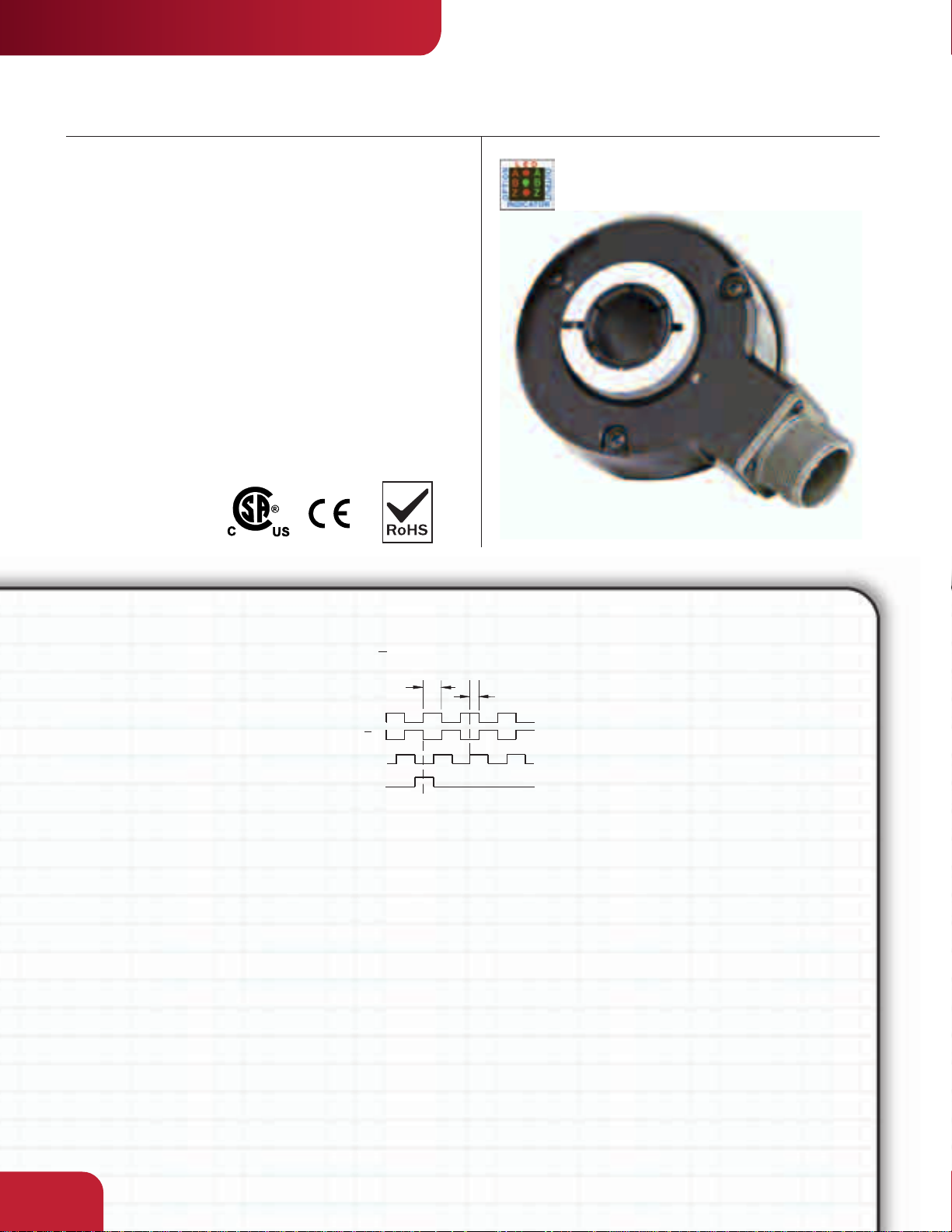
INDUSTRIAL DUTY
SERIES HS35
Sealed Hollowshaft Encoder
Key Features
• The Original Vector-Duty
Hollowshaft Size 35 Encoder
• Electrically Isolated Shaft
Sizes up to 1.25”
• Multitude of Configurations
and Accessories Available
• Hazardous Location
Certification Available
Dynapar
™
brand
SPECIFICATIONS
STANDARD OPERATING CHARACTERISTICS
Code: Incremental
Resolution: 1 to 2500 PPR (pulses/revolution)
Accuracy: (worst case any edge to any other
edge) ±7.5 arc-min.
Format: Two channel quadrature (AB) with
optional Index (Z) and complementary outputs
Phase Sense: A leads B for CW shaft rotation
viewing the shaft clamp end of the encoder
Quadrature Phasing: 90° ± 22.5° electrical
Symmetry: 180° ± 18° electrical
Index: 180° ± 18° electrical (gated with B low )
Waveforms: Squarewave with rise and fall times
less than 1 microsecond into a load capacitance
of 1000 pf
ELECTRICAL
Input Power: (each output)
4.5 min. to 26 VDC max. at 100 mA max., not
including output loads
Outputs:
7273 Open Collector: 30 VDC max., 40 mA sink
max.
7272 Push-Pull and Differential Line Driver: 40
mA sink or source
4469 Differential Line Driver: 100 mA sink or
source
Frequency Response: 100 kHz min.
Electrical Protection: Overvoltage, reverse
voltage and output short circuit protected
Noise Immunity: Tested to EN61326 (Industrial)
for Electro Static Discharge, Radio
Frequency Interference, Electrical Fast
Transients, Conducted and Magnetic Interference
DATA AND INDEX
Not all complements shown.
A shown for reference
o
( 180 ELE C)
Data A
Data A
Data B
Index
A Leads B CW
Mating Connector:
6 pin, style MS3106A-14S-6S (MCN-N4);
7 pin, style MS3106A-16S-1S (MCN-N5);
10 pin, style MS3106A-18-1S (MCN-N6)
5 pin, style M12: Cable with connector available
8 pin, style M12: Cable with connector available
MECHANICAL
Bearing Life: 80,000 hours at 3600 RPM; 128,000
hours at 1800 RPM
Shaft Loading: 40 lbs. radial, 30 lbs. axial
Shaft Speed: 3600 RPM max. (Important: see
Operating Temperature derating for >1800 RPM)
Shaft Bore Tolerance: Nominal +0.0003” +0.0005”
(+0.008/+0.013 mm)
Mating Shaft Requirements:
Runout: ±0.025" (063 mm) radial typical ;
Endplay: ±0.050" (1.27 mm) axial typical ;
Minimum: 1.25" (32 mm) recommended;
Maximum: 2.0" (51 mm) to fit inside cover;
Solid shaft recommended; keyway allowed; flatted
shaft should not be used
o
(90 ELE C)
Starting Torque: 5.0 oz-in max.
Running Torque: 4.5 oz.-in max.
Moment of Inertia:
≤ 5/8" bore: 7.9 x 10
> 5/8" bore: 25.6 x 10
Weight: 16 oz. max.
ENVIRONMENTAL
Operating Temperature:
Standard:
Extended:
≤ 5/8" bore: Derate 5 °C per 1000 RPM above
1800 RPM;
> 5/8" bore: Derate 10 °C per 1000 RPM above
1800 RPM.
Storage Temperature: –40 to +90 °C
Shock: 50 Gís for 11 milliseconds duration
Vibration: 5 to 2000 Hz at 20 Gs
Humidity: to 98% without condensation
Enclosure Rating: NEMA4/IP67
Hazardous Location Certification:
Available as Optional Feature. Class I, Division
2, Group A, B, C & D. CSA File No. LR86404
–40 to +70 °C;
–40 to +100 °C;
-4
oz–in–sec
-4
oz–in–sec
2
2
2.40
by
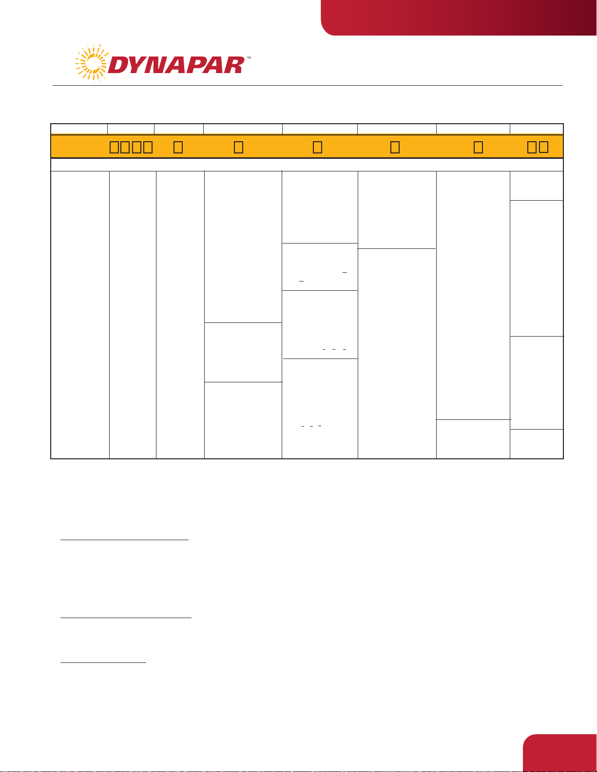
Code 1: Model
HS35
HS35 Size 35
heavy-duty,
sealed
hollowshaft
encoder
Ordering Information
To order, complete the model number with code numbers from the table below:
Code 2: PPR
0500
0001
0512
0003
0600
0010
0900
0012
1000
0050
1024
0060
1200
0064
1270
0100
1500
0120
1800
0240
2000
0250
2048
0300
2400
0360
2500
Code 3: Bore Size
0 6 mm
1 1/4"
2 5/16"
3 8 mm
4 3/8"
5 10 mm
6 12 mm
7 1/2"
8 5/8"
9 15 mm
A 16 mm
B 19 mm
C 3/4"
D 20 mm
E 7/8"
F 24 mm
G 1"
H 1-1/8"
P 1-1/4"
Code 4: Fixing
0 None - customer
supplied
1 Clearance hole for
3/8" bolt on 5.88"
dia. bolt circle
(to fit 4-1/2" NEMA
C-face)
2 Clearance hole for
1/2" bolt on 7.25" dia.
bolt circle
(to fit 8-1/2" NEMA
C-face)
3 Slotted hole for
bolt on 2.5" to 4.0"
radius (to fit
standard AC motor
fan cover slots)
Available when Code 5 is
0-4:
4 Same as '1', w/
cover kit
5 Same as '3', w/
cover kit
Available when Code 5 is
5:
6 Same as '1' w/ dual
cover kit
7 Same as '3' w/ dual
cover kit
Code 5: Format
Ordering Information
0 single ended,
undirectional (A)
1 single ended,
bidirectional (AB)
2 single ended,
bidirectional with
index (ABZ)
available when Code 6
is 3, 4, 5, 6, A or B:
3 differential,
bidirectional ( AA
BB)
available when Code 6
is 3, 4, 5, 6, A or B
and Code 7 is 2, 3,
or 7 thru G, J:
4 differential,
bidirectional with
index ( AA BB ZZ)
available when Code 6
is 3, 4, 5, 6, A or B,
and Code 7 is 2, 7,
A thru G, J:
5 Dual isolated
differential, bidirectional w/index
(AABBZZ)
0 5-26V in, 5-26V
available when Code 5
INDUSTRIAL DUTY
SERIES HS35
Code 6: Output
open collector out
1 5-26V in, 5-26V
open collector out
w/ 2.2kΩ pullups
2 5-26V in, 5-26V
push-pull out
is 3, 4 or 5:
3 5-26V in, 5V line
driver out (7272)
4 5-26V in, 5-26V line
driver out (7272)
5 5-26V in, 5 V
Differential Line
Driver out (4469)
6 5-15V in, 5-15 V
Differential Line
Driver out (4469)
A same as '3' with
extended temp. to
100˚C
B same as '4' with
extended temp. to
100˚C
Code 7: Termination
0 6 pin connector
1 7 pin connector
2 10 pin connector
3 12 pin connector
5 6 pin connector,
plus mating
connector
6 7 pin connector,
plus mating
connector
7 10 pin connector,
plus mating
connector
8 12 pin connector,
plus mating
connector
A 18" (.5m) cable
B 36" (1m) cable
C 72" (2m) cable
D 10' (3m) cable
F 13" (.3m) cable
with 10 pin
connector plus
mating connector
G 13" (.3m) cable
J 8 Pin M12
Connector
available when Code 5
is 0 thru 2
H 5 Pin M12
Connector
Code 8: Options
D2 Hazardous
Location
Certified
available when
Code 7 is 2
D3 Same as D2
including
adapter for
CSA Div. 2,
Group F & G
Certification
(see specifications)
Note: Requires
use of Mating
Cable Assembly
114074-XXXX
available when Code 7
is 0 or 5 and Code 5
is 0-2, or Code 7 is
1, 2, 6, 7:
PS LED Output
Indicator
Not provided with
“Hazardous
Location Certified”
Option
Leave Blank : No
Option
109473-0001 Tether kit (clearance hole for 3/8" bolt on 5.88" dia. bolt circle)
109473-0002 Tether kit (clearance hole for 1/2" bolt on 7.25" dia. bolt circle)
109473-0003 Tether kit (slotted hole for bolt on 2.5" to 4.0" radius)
112121-0001 Spare Hub Clamp (Bore size Code 3: 0 - 9)
112121-0002 Spare Hub Clamp (Bore size Code 3: A - H)
110533-0001 Cover Kit, 56C face
10 foot Cable Assemblies with MS Connector
108594-0010 6 Pin MS, Cable Assy. For Use with Single Ended Outputs
108595-0010 7 Pin MS, Cable Assy. For Use with Single Ended Outputs
108596-0010 7 Pin MS, Cable Assy. For Use with Differential Line Driver w/o Index Outputs
1400635-0010 10 Pin MS, Cable Assy. For Use with Differential Line Driver with Index Outputs
112123-0010 6 Pin MS, Cable Assy. For Use with Differential Line Driver without Index Outputs
108615-0010 12 Pin CCW MS, Cable Assy.
15 foot Cable Assemblies with M12 Connector
112859-0015 5 Pin M12, Cable Assy. For Use with Single Ended Outputs
112860-0015 8 Pin M12, Cable Assy. For Use with Single Ended Outputs
112860-0015 8 Pin M12, Cable Assy. For Use with Differential Line Driver Outputs
Mating Connectors (no cable)
6 pin, style MS3106A-14S-6S (MCN-N4)
7 pin, s
tyle MS3106A-16S-1S (MCN-N5)
10 pin, s
tyle MS3106A-18-1S (MCN-N6)
110533-0002 Cover Kit, fan cover
110533-0003 Dual Cover Kit, 56C face
110533-0004 Dual Cover Kit, fan cover
114064-0001 Adapter Kit, CSA Division 2, Group F & G, Cert.
114074-XXXX D3 Mating Cable Assembly. “-XXXX” denotes length in
feet; example -0010 equals 10 feet.
2.41

INDUSTRIAL DUTY
o
c
g
g
e
o
g
g
g
n
C
e
SERIES HS35
ELECTRICAL CONNECTIONS
6, 7 & 10 Pin MS Connectors and Cables - Code 7= 0 to 8, A to G
onnector & mate/accessory cable assembly pin numbers and wire color information is provided here for
ference. HS35 models with direct cable exit carry the same color coding as shown for each output configuration.
Cable
#108595-*
7 Pin
(If Used)
Wire
Pin
Color
A
BRN
B
ORN
C
YEL
D
RED
E
—
F
BLK
G
GRN
—
—
—
—
—
—
—
—
—
—
Encoder
Function
Sig. A
Sig. B
Sig. Z
Power +V
N/C
Com
Case
_
Sig. A
_
Sig. B
_
Sig. Z
0V Sense
5V Sense
Cable
#108594-*
6 Pin
Single Ended
Wire
Pin
Color
BRN
E
ORN
D
YEL
C
RED
B
F
A
—
—
—
—
—
—
—
BLK
—
—
—
—
—
—
Cable
#112123-*
6 Pin Dif Line
Drv w/o Id x
Wire
Pin
Color
E
BRN
D
ORN
—
B
—
A
—
C
F
—
—
—
—
RED
—
BLK
—
BRN/WHT
ORN/WHT
—
—
—
Cable
#108596-*
7 Pin Dif Line Drv
w/o Id x
Wire
Pin
Color
A
BRN
B
ORN
—
D
—
F
G
C
E
—
—
—
—
RED
—
BLK
GRN
BRN/WHT
ORN/WHT
—
—
—
Dynapar
Cable
#1400635-*
10 Pin
(If Used)
Wire
Pin
Color
A
BRN
B
ORN
C
D
E
F
G
H
J
—
—
I
YEL
RED
—
BLK
GRN
BRN/WHT
ORN/WHT
YEL/WHT
—
—
#108615-*
12 Pin CCW
(If Used)
Pin
5
8
3
12
7
10
9
6
1
4
2
11
Cable
Wire
Color
BRN
ORN
YEL
RED
—
BLK
—
BRN/WHT
ORN/WHT
YEL/WHT
GRN
BLK/WHT
™
brand
Enc
Fun
Si
Si
*Si
Pow
C
Si
Si
*Si
* I
5 & 8 Pin M12 Accessory Cables when Code 7= H or J
Connector pin numbers and cable assembly wire color information
is provided here for reference.
Encoder Cable # 112859-* Cable # 112860-* Cable # 112860-*
Function 5 Pin Single Ended 8 Pin Single Ended 8 Pin Differential
Pin Wire Color Pin Wire Color Pin Wire Color
Sig. A
Sig. B
†Sig. Z
Power +V
Com
Sig. –A
–
Sig.
B
–
†Sig.
Z
Cable Configuration: PVC jacket, 105 °C rated, overall foil shield; 24 AWG conductors, minimum
*Note: Standard cable length is 10 feet but may be ordered in any length in
5 foot increment. For example, -0020 is a 20 foot cable.
†Note: Index not provided on all models. See ordering information
See “Accessories” Section for Connectors and Cable Assemblies Ordering Information
2.42
4
2
5
1
3
–
–
–
BLK
WHT
GRY
BRN
BLU
–
–
–
1
4
6
2
7
–
–
–
BRN
ORG
YEL
RED
BLK
–
–
–
1
4
6
2
7
3
5
8
BRN
ORG
YEL
RED
BLK
BRN/WHT
ORG/WHT
YEL/WHT
s

by
4, 5, 6, 7
Cover Option
DIMENSIONS
DUST COVER
(INCLUDED)
MOUNTS ON
EITHER SIDE
.48"
12.2 mm
36.8 mm
Fan Cover Motor Mount
1.45"
1.8"
45.7 mm
63.5 mm
[SEE CODE 4]
MOUNTS ON
EITHER SIDE
1.93" DIA. MAX.
3
2.5"
TETHER
49.0 mm
Code 4: Fixing
4.0"
101.6 mm
[SEE CODE 4]
2.25"
57.2 mm
MAX.
3.54" DIA.
89.9 mm
SERIES HS35
TETHER MOUNTING HOLES
2x #6-32 x .25" dp. on Ø2.437" B.C.
BOTH SIDES
1, 3
Machine Mount
2.93" or 3.63"
74.4 mm or
92.17 mm
[SEE CODE 4]
INDUSTRIAL DUTY
4, 5, 6, 7
Cover Option
0.300" TYP
0, 1
6 & 7 Pin MS
3.54"
89.9 mm
0.54"
13.7 mm
SLOTTED HOLE FOR
1/4", 5/16", OR 3/8" BOLT
2
10 Pin MS
3.92"
99.6 mm
0.54"
13.7 mm
Code 7: Termination
3
12 Pin MS
2.87"
72.9 mm
H, J
5 & 8 Pin M12
3.10" max.
78.7mm
6.60"
0.48 THRU
HOLES ON
5.875 B.C.
(6 PLACES)
3.300"
A-G
Cables
3.0"
76.2 mm
6 & 7 Pin and 10 Pin shown with
LED Output Indicator Option - Code 8: PS
2.43
 Loading...