

Page 1
Incremental Shaft Encoders
Type RI 76 TD
NUMBER OF PULSES
TECHNICAL DATA
mechanical
Industrial types
■ Through shaft with up to diameter 42 mm
■ Short overall length with an outside diameter of only 76 mm
■ Easy installation by means of clamping ring
■ Operating temperature up to 100 °C
■ Application e.g.:
- motors
- printing machines
- lifts
50 / 100 / 128 / 250 / 256 / 300 / 314 / 360 / 500 / 600 / 720 / 900 / 1000 / 1024 / 1250 / 1500 / 2048 /
2500 / 3072 / 4096 / 5000 / 8192 / 9000 / 10000
Other number of pulses on request
Shaft fixation Clamping ring, front or rear
Coupling stator coupling (hubshaft with tether)
Shaft diameter 15…42 mm (Available: 15, 16, 18, 20, 24, 25, 27,
28, 30, 32, 38, 40, 42 mm as well as 5⁄ 8 “, 15⁄ 8“, 3⁄ 4 “
Mimimum length of mounting shaft
Front clamping ring 32 mm with Ø 15 ... 30, 35 mm with Ø >30 ... 42
Rear clamping ring corresponding to total length of encoder
Max. parallel shaft misalignment
with stator coupling A (flexible) ±2.0 mm axial, ±0.15 mm radial
with 1x stator coupling N (torsionally rigid) ±0.5 mm axial, ±0.3 mm radial
with 2x stator coupling N (torsionally rigid) ±0.3 mm axial, ±0.2 mm radial
Absolute max. speed at 70 °C and IP64: 3 600 min-1für Ø 15 ... 25
at 70 °C and IP64: 1 800 min
at 70 °C and IP40: 6 000 min
at 100 °C always: 1 800 min-1für Ø 15 ... 42
Torque 3…10 Ncm (depending on version )
Moment of inertia 140...420 gcm2(depending on version)
Protection class (EN 60529) Housing IP50, bearings IP40
Option: Housing IP65, bearings IP64
Operating temperature -25 ... +100 °C
Storage temperature -25 ... +100 °C
Vibration resistance (IEC 68-2-6) 10 g = 100 m/s2(10 ... 2000 Hz)
Shock resistance (IEC 68-2-27) 100 g = 1000 m/s2(6 ms)
Connection 1.5 m cablel1radial
Housing Aluminium
Weight 320 - 580 g (depending on version)
1
Other cable length on request
Hollow shaft
-1
für Ø >25 ... 42
-1
für Ø 15 ... 42
74 ENCODERS COUNTERS INDICATORS RELAYS PRINTERS CUTTERS
Page 2
Incremental Shaft Encoders
Type RI 76 TD
TECHNICAL DATA
electrical
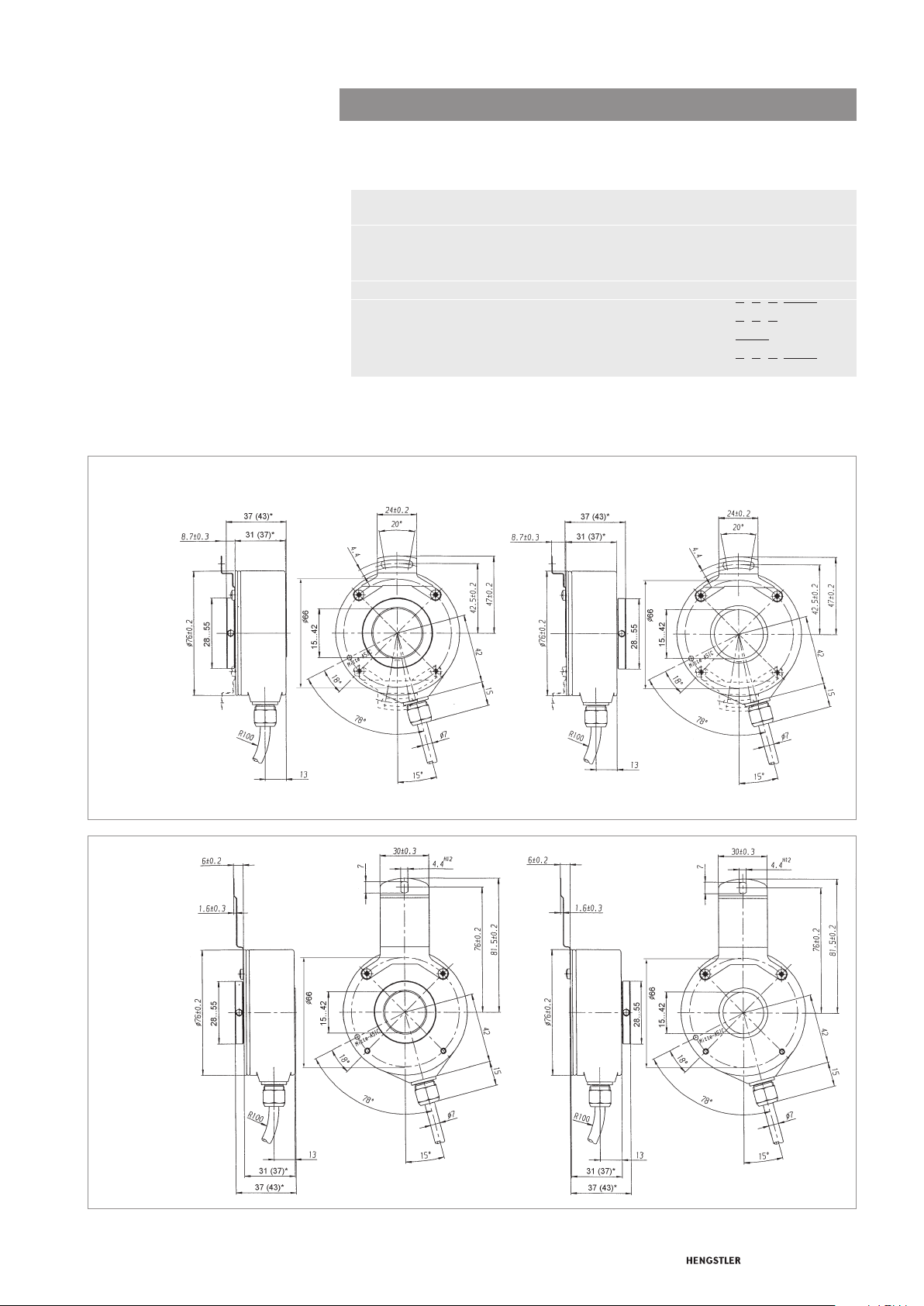
DIMENSIONAL DRAWINGS
WITH HUBSHAFT WITH TETHER
”RIGID”
Industrial types
General design as per DIN EN 61010-Part 1, protection class III,
Contamination level 2, over voltage level II
Supply voltage with RS 422 +Sense (T): DC 5V±10%
(SELV) with RS 422 +Alarm (R): DC 5 V ±10 % oder DC 10 - 30 V
with push-pull (K, I): DC 10 - 30 V
Max. current w/o load max. 60 mA (DC 5 V), 60 mA (DC 10 V), 35 mA (DC 24 V)
Standard RS 422 (R): A, B, N, , , ,
output versions
1
Pole protection with supply voltage DC 10 - 30 V
2
Output description and technical data see chapter “Technical basics”
2
RS 422 (T): A, B, N, , , , Sense
push-pull (K): A, B, N,
push-pull complementary (I): A, B, N, , , ,
Hollow shaft
1
AlarmNBA
NBA
Alarm
AlarmNBA
1
Dimensions in mm
* Values in brackets for shaft diameter >30
Diameter of connection shaft 15g8 … 42g8
WITH HUBSHAFT WITH TETHER
”FLEXIBLE”
Dimensions in mm
* Values in brackets for shaft diameter >30
Diameter of connection shaft 15g8 … 42g8
R for alternating bending > 100 mm
R for permanent bending > 40 mm
R for alternating bending > 100 mm
R for permanent bending > 40 mm
75ENCODERS COUNTERS INDICATORS RELAYS PRINTERS CUTTERS
Page 3

Incremental Shaft Encoders
Type RI 76 TD
SHAFT CONNECTION
MOUNTING NECESSITIES
PIN ASSIGNMENT
Cable TPE
Industrial types
Shaft fixing is done through a clamping ring either on the flange or cap side. As a rule,
flange side clamping is better for smaller motors as the available shaft stub is correspondingly shorter.
On the other hand, cap side clamping is easier when there is sufficient shaft length
available.
In order to compensate for axial and radial shaft eccentricity as well as any angle offset, the
encoder flange must not be rigidly mounted. Please mount the flange with a flexible stator
coupling (e.g. hubshaft with tether) as torque support.
There are two flexible mounting plates:
• A flexible hubshaft with tether (A) for higher levels of play and lower requirements
for accuracy.
• A rigid hubshaft with tether (N) for reduced play and rigid connection with reduced
swing angle. This is suitable in the case of higher accuracy and dynamics requirements.
Output circuit
Colour (TPE) RS 422 RS 422 push-pull (K) push-pull
+ Sense (T) + Alarm (R) complementary (I)
brown Channel A Channel A Channel A Channel A
green Channel Channel Channel
grey Channel B Channel B Channel B Channel B
pink Channel Channel Channel
red Channel N Channel N Channel N Channel N
black Channel Channel Channel
violet (white)2 Sense GND
blue Sense V
brown/green DC 5 V DC 5/10.- 30 V DC 10 - 30 V DC 10 - 30 V
white/green GND GND GND GND
Cable screen
1
connected with encoder housing
2
white for version Sense (T)
1
CC
Cable screen1Cable screen1Cable screen1 Cable screen
Sense V
CC
Hollow shaft
AAA
BBB
NNN
AlarmAlarmAlarm
Sense V
CC
1
ACCESSORIES
76 ENCODERS COUNTERS INDICATORS RELAYS PRINTERS CUTTERS
Hubshaft with tether flexible ordering code 1 533 079
Hubshaft with tether rigid ordering code 1 533 078
Page 4

Incremental Shaft Encoders
Type RI 76 TD
Industrial types
ORDERING INFORMATION
Stator
coupling
Shaft
Type Model
Number
of pulses
Supply
voltage
Flange Protection
.
1
RI76 TD High
1
only with output R, T,
2
only with output R, K, I
3
Available with front clamping ring and IP40: 15, 20, 24, 25, 27, 28, 30, 38, 40, 42, 50 (5⁄ 8
Available with front clamping ring and IP64: 15, 16, 18, 20, 24, 25, 27, 28, 30, 32, 38, 40, 42, 50 (
Available with rear clamping ring and IP40: 25, 28, 30, 32, 38, 40, 42
Available with rear clamping ring and IP64: 20, 25, 30, 32, 38, 40, 42
Preferably available versions are printed in bold type.
Others: please request delivery time
temperature,
direct
hollow shaft
1…10 000
A DC 5 V
E DC
10-30 V
Clamping
shaft with
2
D Front
clamping
ring
H Rear
clamping
ring
1 IP40
4 IP64
O without
A flexible
N rigid
15…42 metric
50…99
coded by inches
50 =
51 = 15⁄ 8 “
52 =
“), 51 (1
Hollow shaft
Output Connection
in mm
5
⁄ 8
“
3
⁄ 4“
5
⁄ 8
“)
5
⁄ 8 “), 51 (15⁄ 8 “), 52 (3⁄ 4 “)
R RS 422 +
Alarm
T RS 422
+ Sense
K push-pull
I push-pull
complementary
F TPE cable
radial
77ENCODERS COUNTERS INDICATORS RELAYS PRINTERS CUTTERS
 Loading...