

DANA Spicer Torque-Hub W3B Series, Spicer Torque-Hub W3C Series Service Manual
1
Torque-Hub® Planetary Final Drive
W3B/W3C Series Service Manual
Rev 03/07/13

2
Fairfield Manufacturing Co. Inc., Lafayette, IN, is now a part of Dana Incorporated
While every precaution has been taken in the preparation of this document, Fairfield Manufacturing Co. Inc. assumes no
liability with respect to the use of the documentation described herein, or for any act or omission of Fairfield Manufacturing
Co. Inc. concerning this documentation. Torque-Hub® is a registered trademark of Fairfield Manufacturing Co. Inc.
Features and specifications are subject to change without notice.

3
Planetary Final Drive Service Manual
Content
Introduction
04
Roll and Leak Test
05
Tightening and Torquing Bolts
07
Lubrication Information
08
Disassembly Instructions
Main Disassembly
12
Carrier Disassembly
15
Coupling Disassembly
16
Input Shaft Disassembly
17
Cover Disassembly
18
Housing-Spindle Disassembly
19
Assembly Instructions
Cover Subassembly
24
Carrier Subassembly
26
Housing Spindle Subassembly
28
Coupling Subassembly
30
Input Shaft Subassembly
31
Main Assembly
32
Assembly Drawing
36
Parts List 37
Assembly Tools
40
General Information
Contact Information
52

4
Planetary Final Drive Service Manual
Introduction
This manual is a step-by-step guide to the disassembly and
assembly of the W3C/W3B Series Torque-Hub® units. It is designed
for the customer or mechanic who is repairing this particular
Torque-Hub® model.
Users of this manual should note that each part mentioned is
followed by an identification number enclosed in parentheses.
These part numbers may be referred to in the Parts List and
Assembly Drawing sections of this manual.
Specialized tools used to assemble this unit are noted in the
assembly procedures and diagrammed in the Assembly Tools
section.
Users should familiarize themselves with the procedures for roll and
leak testing, as well as bolt tightening and torquing found on the
following three pages before starting any repairs.
Standard safety practices should be followed during the
disassembly and assembly procedures described. Safety glasses
and safety shoes should be worn, and heavy, heat resistant gloves
should be used when handling heated components. Be especially
alert when you see the word CAUTION. This indicates that a
particular operation could cause personal injury if not performed
properly or if certain safety procedures are not followed. The word
NOTE is used to bring attention to certain procedures or helpful
hints that will aid in the disassembly and assembly process.
5
Planetary Final Drive Service Manual
Roll and Leak Test
Torque-Hub® units should always be roll and leak tested before
disassembly (if possible) and after assembly to make sure the unit’s
gears, bearings, and seals are working properly. The following
information briefly outlines what to look for when performing these
tests.
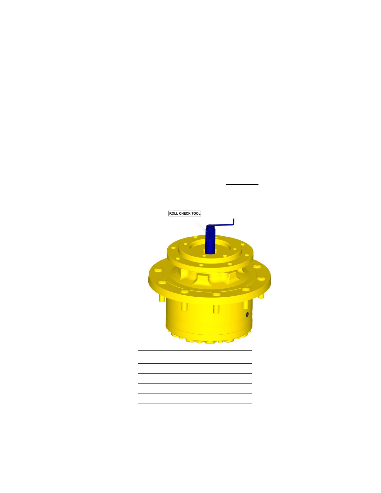
The Roll Test The purpose of the roll test is to determine if the unit’s gears are
rotating consistently, easily and properly. Release the brake by
applying 400 Psi to the brake port. To perform a roll test, use the
recommended tool from table below (or something equivalent) to
apply constant rotational force to the input of the gearbox. If more
drag is felt in the gears only at certain points, then the gears are not
rolling consistently and easily and should be examined for improper
installation or defects. Some gear packages roll with more difficulty
than others. Do not be concerned if the gears in the unit seem to roll
hard as long as they roll with consistency. Rotate the gearbox both
clockwise and counterclockwise the same number of turns as the
ratio of the unit. The gearbox ratio is the same number as the last
three numbers on the ID tag.
Model code
Roll Test Tool
W3xxxx3xxxx
T223988
W3xxxx4xxxx
T223989
W3xxxx7xxxx
T223990
W3Bxxx8xxxx
T223997
Continued on Next Page
6
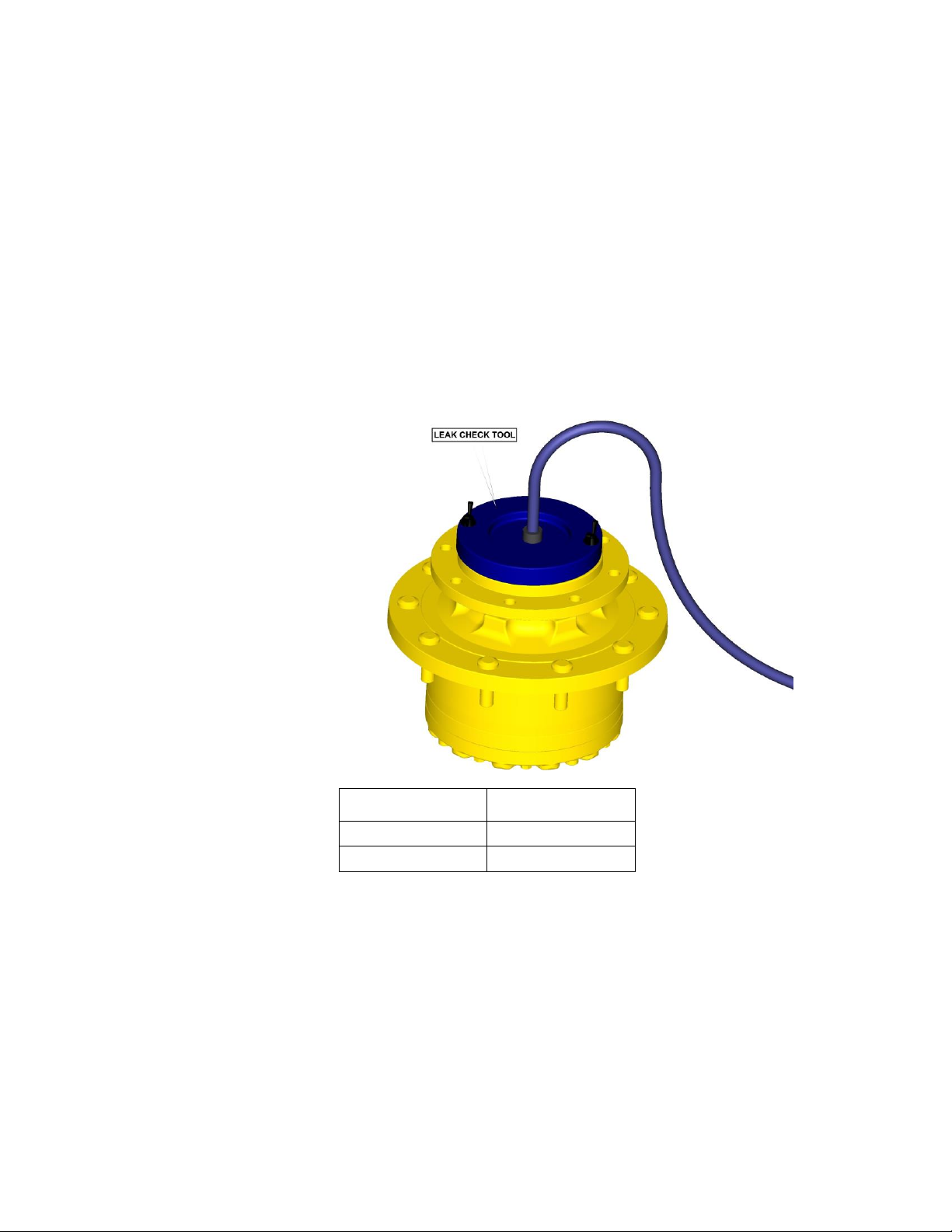
The Leak Test The purpose of a leak test is to make sure the unit is airtight. To
perform a leak test use the leak test fixture from the table below. If
the tool is not available, the gearbox must be sealed to perform the
test. This can be accomplished by assembling the sealed input
device onto the gearbox at the input end and replace one of the oil
plugs with an air chuck. DO NOT EXCEED 10 PSI PRESSURE
DURING THE LEAK TEST. Higher pressure will create a false
sealing effect in assemblies with lip-seals. The unit has a leak if the
pressure gauge reading on your leak check fitting starts to fall after
the gearbox has been pressurized and allowed to equalize. Leaks
will most likely occur at the pipe plugs, the main seal or wherever
o-rings or gaskets are located. The exact location of a leak can
usually be detected by brushing a soap and water solution around
the main seal and where the o-rings or gaskets meet on the exterior
of the unit and then checking for air bubbles. If a leak is detected in
a seal, o-ring, or gasket, the part must be replaced and the unit
rechecked. Leak test at 10 psi for 20 minutes.
Model code
Leak Test Tool
W3Cxxxxxxxx
T220225
W3Bxxxxxxxx
T201476
7
Planetary Final Drive Service Manual
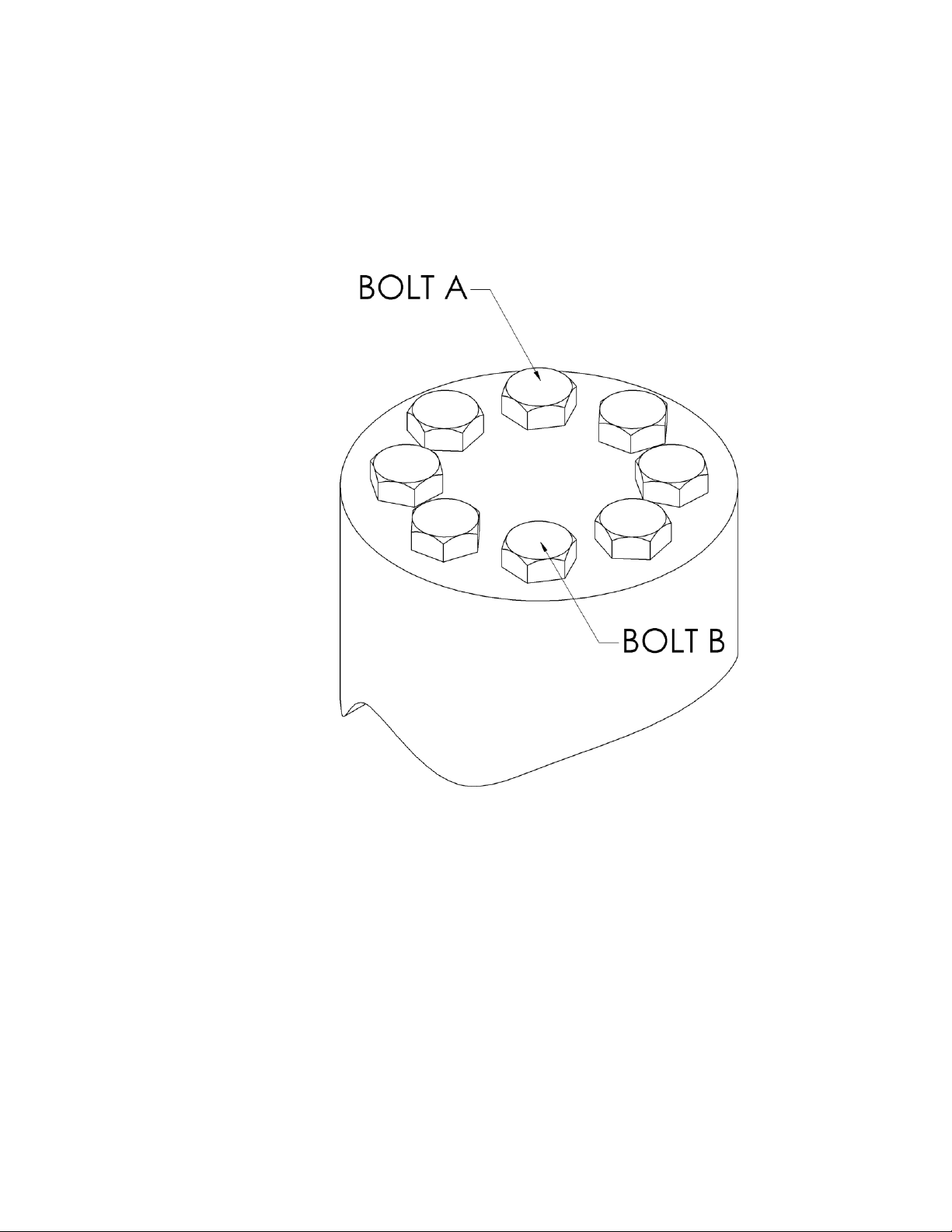
Tightening and Torquing Bolts
If an air impact wrench is used to tighten bolts, extreme care should
be taken to ensure the bolts are not tightened beyond their specified
torque. The following steps describe how to tighten and torque bolts
or socket head cap screws in a bolt circle.
1.
Tighten (but do not torque) bolt “A” until snug.
2.
Go to the opposite side of the bolt circle and tighten bolt “B” until
equally snug.
3.
Crisscross around the bolt circle and tighten the remaining bolts.
4.
Use a torque wrench to apply the specified torque to bolt “A”.
5.
Using the same sequence, crisscross around the bolt circle and
apply an equal torque to the remaining bolts.

8
Planetary Final Drive Service Manual
Lubrication Information
General Properties: The lubricant used in most Torque-Hub® drives should be petroleum
based gear fluid containing anti-oxidation, anti-foaming and extreme
pressure additives. The lubricant should have a minimum viscosity
index of 95 cst and maintain a minimum viscosity of 40 cst under
normal operating conditions. Some applications require special
considerations; consult the machine manufacturer and Fairfield for
more additional information.
The table below lists the recommended viscosities for various
ambient operating temperatures. These recommendations are
based on temperature rise of 50°to 100°F at normal operating
conditions.
Differential Planetary Simple Planetary
Ambient
Temperature
ISO Index
AGMA
Lubricate
Number
ISO Index
AGMA
Lubricate
Number
-40°to -5°F
(1)
VG100
3EP
VG100
3EP
-5°to 40°F
VG150
4EP
VG100
3EP
40°to105°F
VG220/VG320
5EP/6EP
VG150/VG220
4EP/5EP
105°to 150°F
(2)
VG460
7EP
VG320
6EP
Footnotes
1. For operation in this ambient temperature range, synthetic oil is recommended with a pour point of
10°F lower than the minimum ambient temperature.
2. For operation in this ambient temperature range, synthetic oil is recommended for proper lubricant
life at elevated temperatures.
Continued on Next Page

9
Maintenance Oil amounts for each series of Torque-Hub® drives are indicated in
the appropriate series literature. An initial oil change should be
made after the first 50 hours of operation. Subsequent oil changes
should be made at 1,000 hour intervals or annually, whichever
comes first.
Oil temperatures should be not higher than 160°to 180°F for
continuous operation, and no higher than 200°F for intermittent
operation. For special applications, high horsepower, high speeds
or wide temperature changes, please consult Fairfield.
Oil Fill Level When the Torque-Hub® unit is mounted horizontally, unless
otherwise specified, the gearbox should be filled half-full of oil.
Consult the appropriate series literature for approximate fill
volumes. Vertically mounted Torque-Hub® units may require special
lubrication procedures. Please contact Fairfield for vertically
mounted applications.

10
THIS PAGE
INTENTIONALLY
LEFT BLANK

11
DISASSEMBLY
12
Planetary Final Drive Service Manual
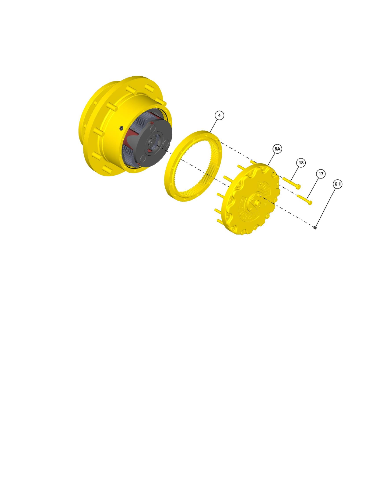
Main Disassembly
1.
Perform roll check and leak check prior to disassembling the unit.
2.
Remove the magnetic Pipe Plug (6H) from Cover Plate (6A) and drain the oil out of the
gearbox.
NOTE: Record the condition and volume of the oil.
3.
Remove eight of Bolts (17) followed by four of Bolts (18) from Cover Subassembly.
4.
Lift the Cover Subassembly off of the unit.
5.
Lift Ring Gear (4) off the unit.
Continued on Next Page
13
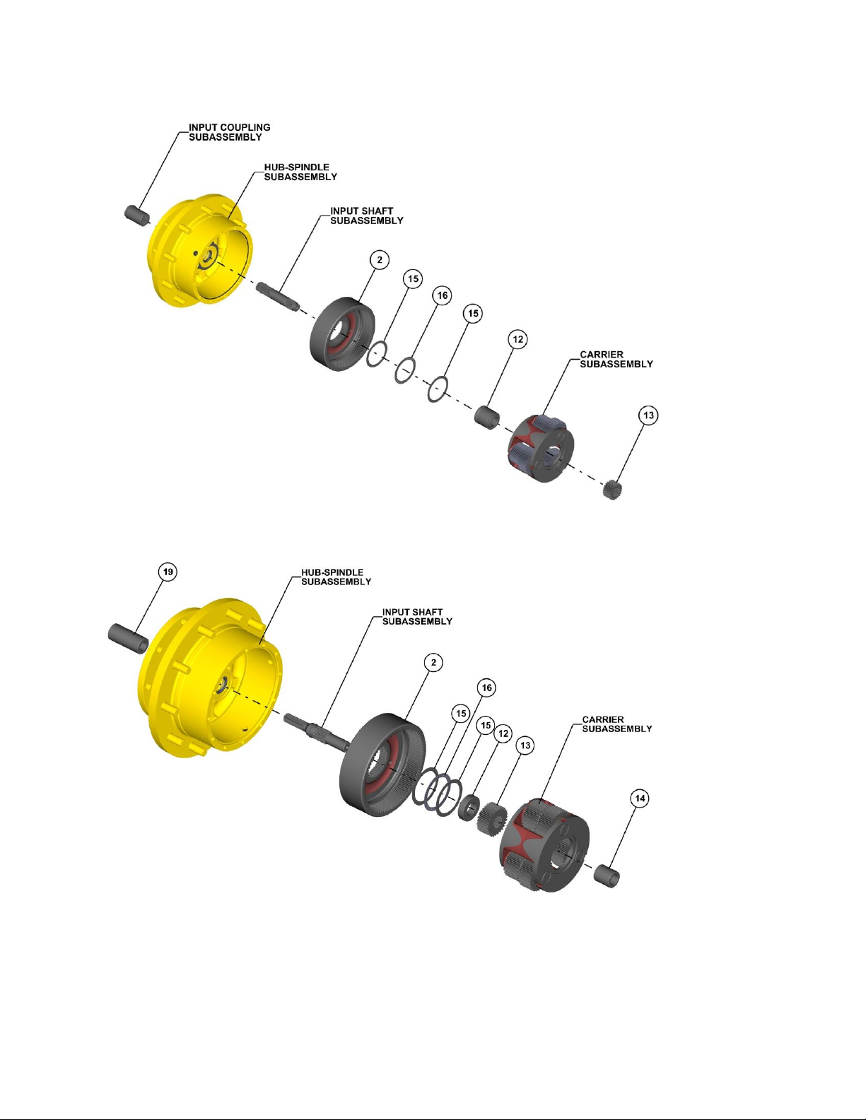
NOTE: Figure 1 refers to 30, 35, 50, 64 & 73 : 1 Ratios
NOTE: Figure 2 refers to 18, 24, 31 & 43 : 1 Ratios
Continued on Next Page

14
6.
If applicable remove Spacer (14) from the Input Shaft (11)
7.
Remove the Sun Gear (13).
8.
Lift out the Carrier Subassembly from the unit.
9.
Remove the Input Spacer (12) from the unit.
10.
Remove two Thrust Spacers (15) and Thrust Bearing (16) from the Internal Gear (2).
11.
Remove Internal Gear (2).from the unit.
12.
Remove Input Shaft Subassembly from the Hub Spindle Subassembly.
13.
Take out Input Coupling Subassembly of the Hub Spindle Subassembly.
This concludes the Main Disassembly.
15
Planetary Final Drive Service Manual
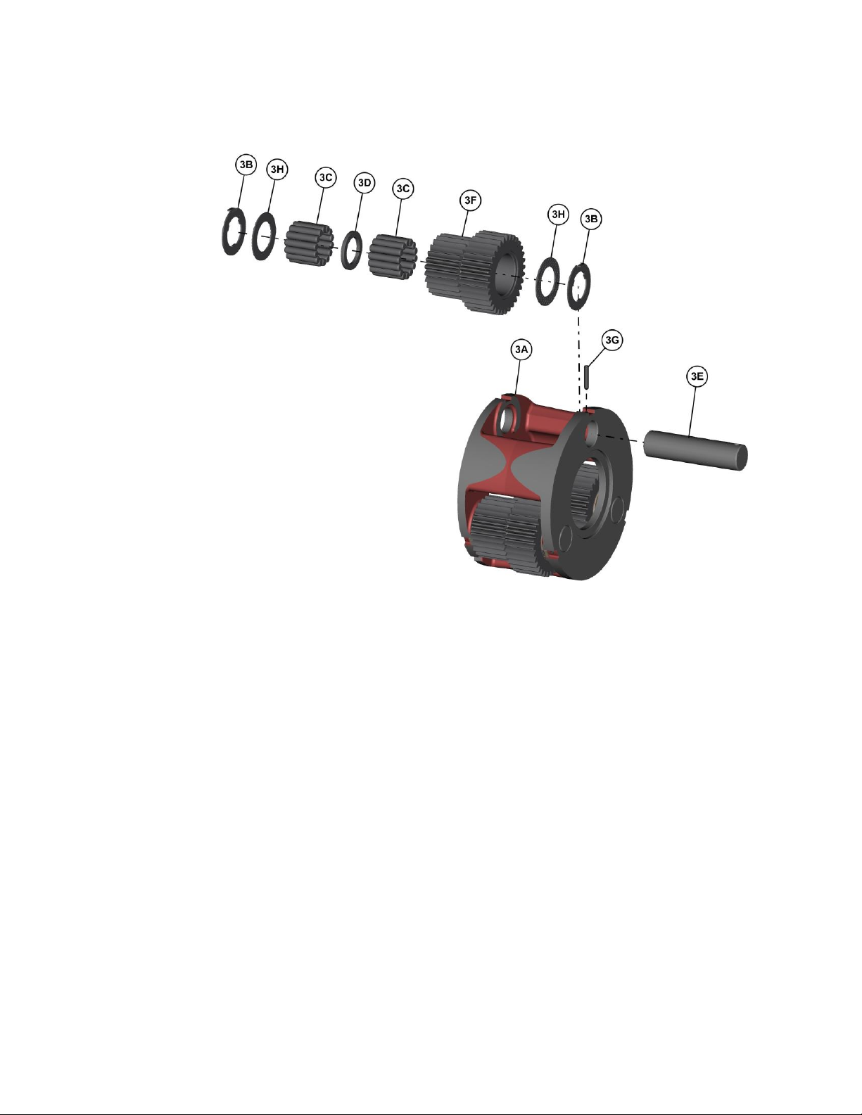
Carrier Disassembly
1.
Drive Planet Shaft (3E) out of the carrier pin holes; forcing the Roll Pin (3G) to sheer off.
2.
Hold on to the Planet Gear (3F) and push the Planet Shaft (3E) out of the Carrier (3A). The
Thrust Washers (3B and 3H) will slide off the shaft as it is removed.
3.
Using a hammer and punch, drive the Roll Pin (3G) out of the Planet Shaft (3E) and Carrier
(3A).
4.
Remove first set of Needle Bearings (3C) from the inside of the Planet Gear (3F).
5.
Remove Thrust Washer (3D) from Planet Gear (3F).
6.
Remove second set of Needle Bearings (3C) from the inside of the Planet Gear (3F).
7.
Repeat steps 1-6 for the remaining two Planet Gears (3F).
This concludes the Carrier Disassembly.
16
Planetary Final Drive Service Manual
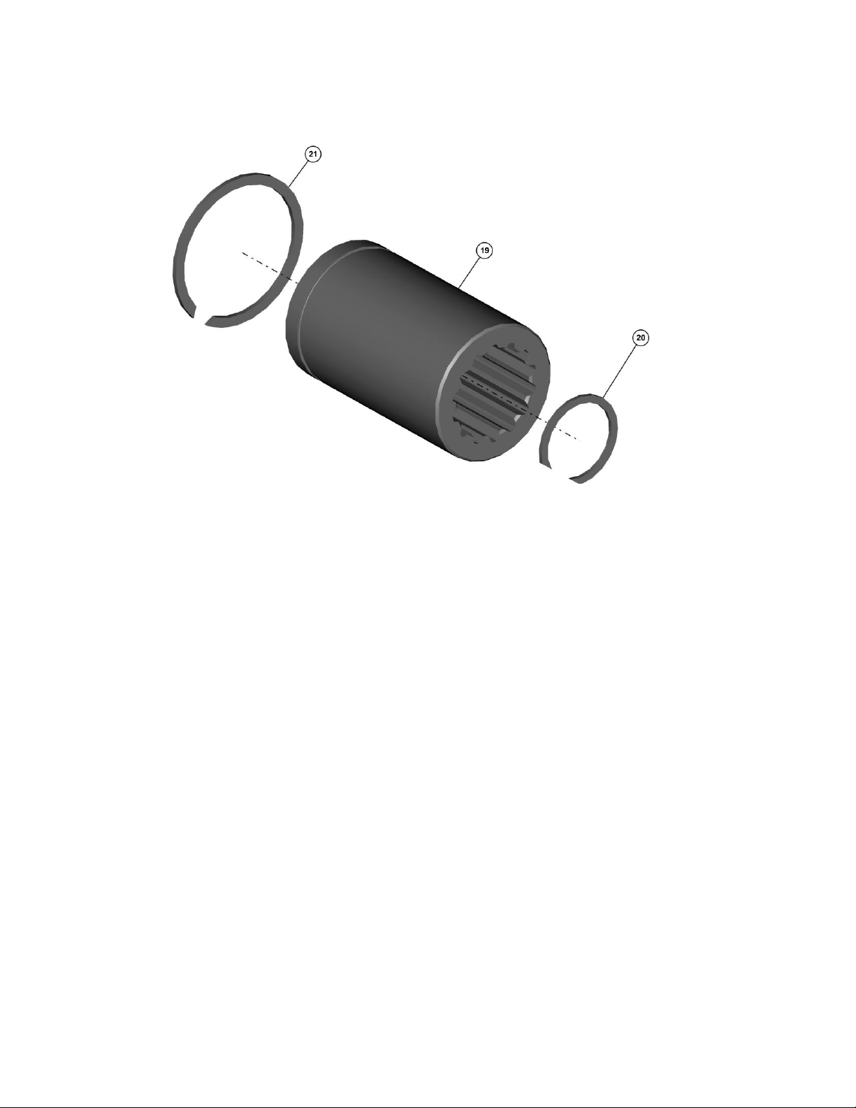
Coupling Disassembly
CAUTION: Safety glasses must be worn during this next steps.
1.
If necessary, remove Internal Retaining Ring (20).from the groove of Coupling (19).
2.
If necessary, remove External Retaining Ring (21) from the groove of Coupling (19).
This concludes the Coupling Disassembly.
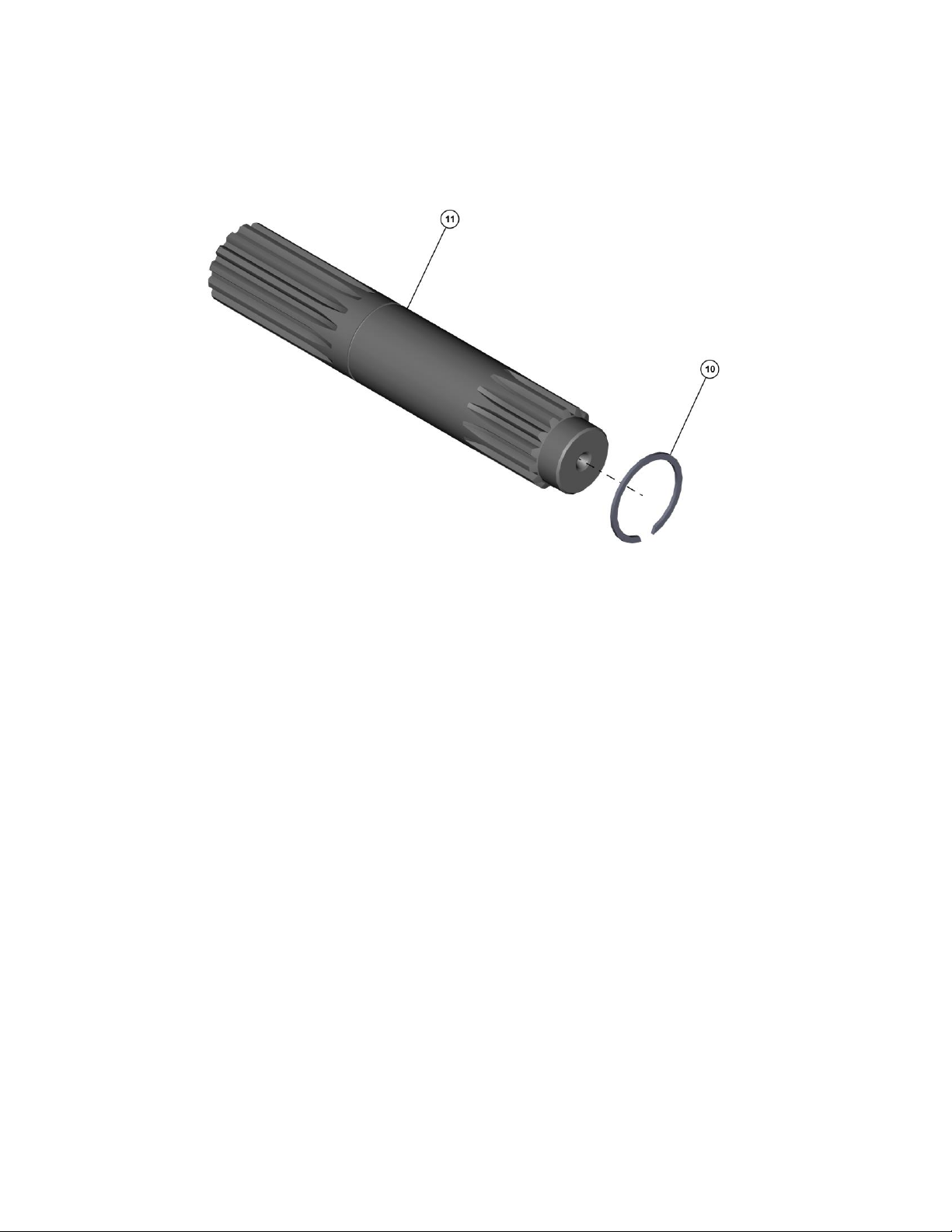
17
Planetary Final Drive Service Manual
Input Shaft Disassembly
CAUTION: Safety glasses must be worn during this next steps.
1. If necessary, remove External Retaining Ring (10) from the groove of the Input Shaft (11).
This concludes the Input Shaft Disassembly.
 Loading...