

1
Torque-Hub® Planetary Final Drive
S350 Series Service Manual
Rev 04/11/13

2
Fairfield Manufacturing Co. Inc., Lafayette, IN, is now a part of Dana Incorporated
While every precaution has been taken in the preparation of this document, Fairfield Manufacturing Co. Inc. assumes no
liability with respect to the use of the documentation described herein, or for any act or omission of Fairfield Manufacturing
Co. Inc. concerning this documentation. Torque-Hub® is a registered trademark of Fairfield Manufacturing Co. Inc.
Features and specifications are subject to change without notice.

3
Planetary Final Drive Service Manual
Content
Introduction
4
Roll and Leak Test
5
Tightening and Torquing Bolts
7
Lubrication Information
8
Disassembly Instructions
Main Disassembly
12
Cover Disassembly
17
Output Carrier Disassembly
18
1st Stage Intermediate Carrier Disassembly
19
2st Stage Intermediate Carrier Disassembly
20
Input Carrier Disassembly
22
Output Pinion Disassembly
23
Assembly Instructions
Cover Subassembly
25
Output Carrier Subassembly
26
1st Stage Intermediate Carrier Subassembly
28
2st Stage Intermediate Carrier Subassembly
30
Input Carrier Subassembly
32
Output Pinion Subassembly
34
Main Assembly
37
Assembly Drawing
43
Parts List 44
Assembly Tools
47
General Information
Contact Information
55

4
Planetary Final Drive Service Manual
Introduction
This manual is a step-by-step guide to the disassembly and
assembly of the S350 series Torque-Hub® units. It is designed for
the customer or mechanic who is repairing this particular TorqueHub® model.
Users of this manual should note that each part mentioned is
followed by an identification number enclosed in parentheses.
These part numbers may be referred to in the Parts List and
Assembly Drawing sections of this manual.
Specialized tools used to assemble this unit are noted in the
assembly procedures and diagrammed in the Assembly Tools
section.
Users should familiarize themselves with the procedures for roll and
leak testing, as well as bolt tightening and torquing found on the
following three pages before starting any repairs.
Standard safety practices should be followed during the
disassembly and assembly procedures described. Safety glasses
and safety shoes should be worn, and heavy, heat resistant gloves
should be used when handling heated components. Be especially
alert when you see the word CAUTION. This indicates that a
particular operation could cause personal injury if not performed
properly or if certain safety procedures are not followed. The word
NOTE is used to bring attention to certain procedures or helpful
hints that will aid in the disassembly and assembly process.
5
Planetary Final Drive Service Manual
Roll and Leak Test
Torque-Hub® units should always be roll and leak tested before
disassembly (if possible) and after assembly to make sure the unit’s
gears, bearings and seals are working properly. The following
information briefly outlines what to look for when performing these
tests.
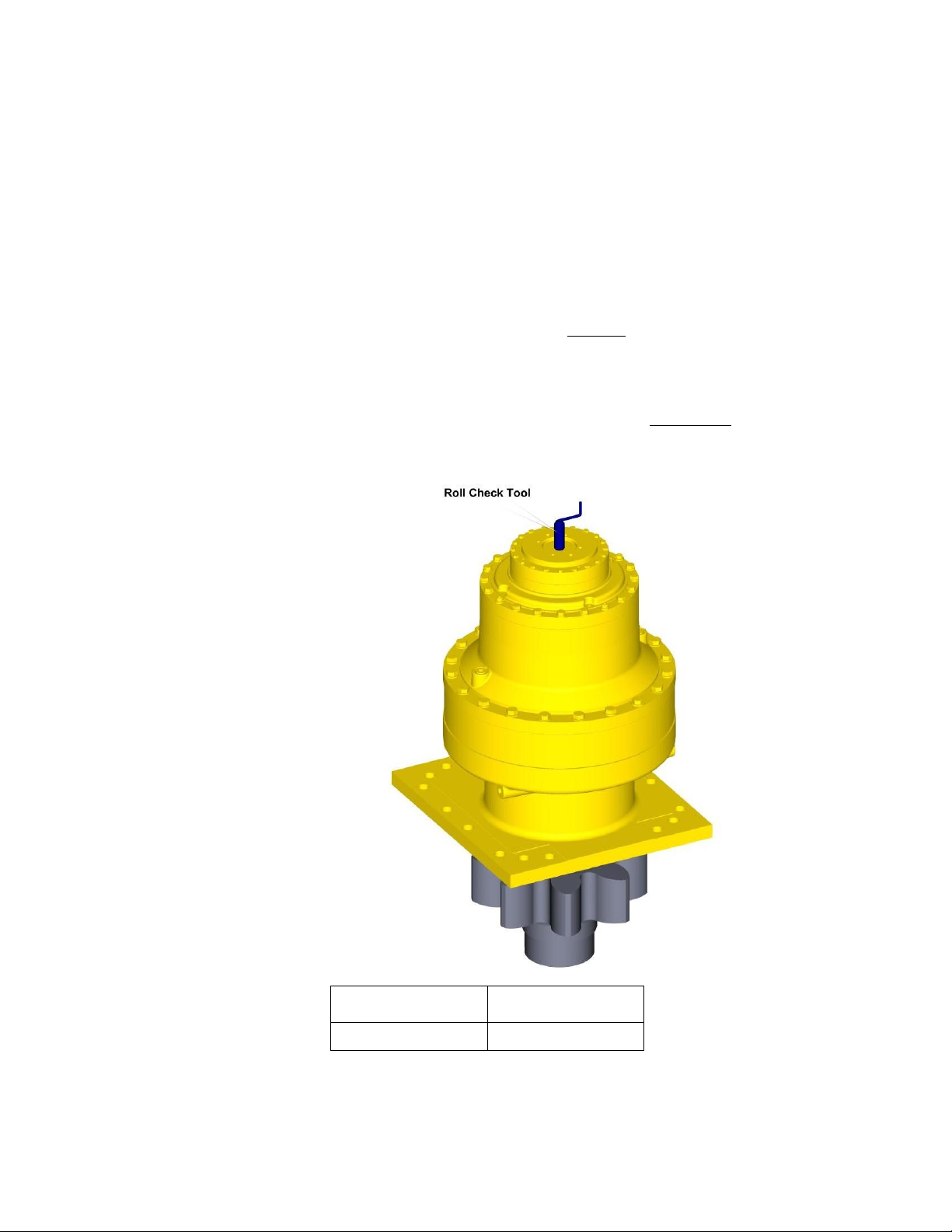
The Roll Test The purpose of the roll test is to determine if the unit’s gears are
rotating consistently, easily and properly. It should be able to rotate
the gears in the unit applying constant force to the roll checker. If
more drag is felt in the gears only at certain points, then the gears
are not rolling consistently and easily and should be examined for
improper installation or defects. Some gear packages roll with more
difficulty than others. Do not be concerned if the gears in the unit
seem to roll hard as long as they roll with consistency. Rotate the
gearbox both clockwise and counterclockwise the same number of
turns as the ratio of the unit. The gearbox ratio is the same number
as the last three numbers on the ID tag.
Model Code
Roll Test Tool
S350Axxxxxxx
T-223989
6
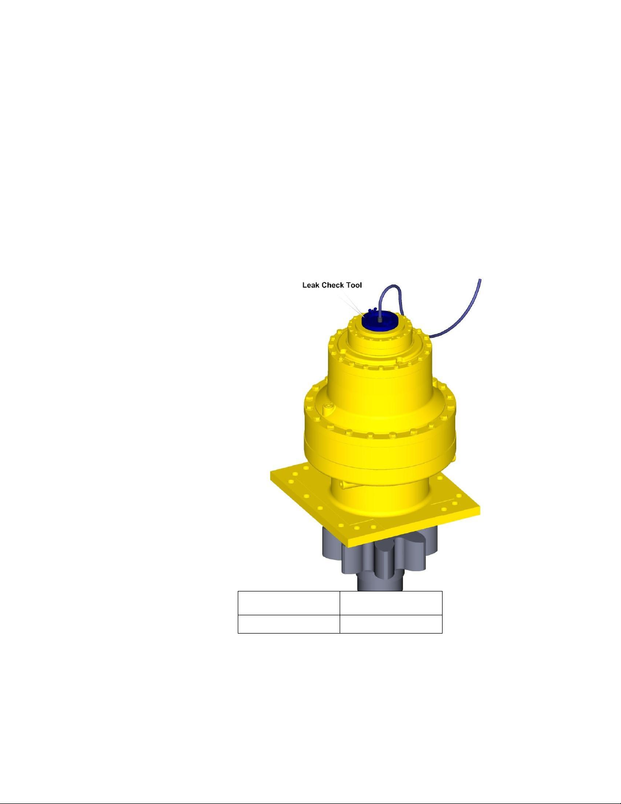
The Leak Test The purpose of a leak test is to make sure the unit is airtight.
To perform a leak test, use the leak test fixture from the table on
page 10. If the tool is not available, the gearbox must be sealed to
perform the test. This can be accomplished by assembling the
sealed input device onto the gearbox at the input end and replace
one of the oil plugs with an air chuck. DO NOT EXCEED 10 PSI
PRESSURE DURING THE LEAK TEST. Higher pressure will create
a false sealing effect in assemblies with lip-seals. The unit has a
leak if the pressure gauge reading on your leak check fitting starts
to fall after the gearbox has been pressurized and allowed to
equalize. Leaks will most likely occur at the pipe plugs, the main
seal or wherever o-rings or gaskets are located. The exact location
of a leak can usually be detected by brushing a soap and water
solution around the main seal and where the o-rings or gaskets
meet on the exterior of the unit and then checking for air bubbles. If
a leak is detected in a seal, o-ring or gasket, the part must be
replaced and the unit rechecked. Leak test at 10 psi for 20 minutes.
Model Code
Leak Test Tool
S350Axxxxxxx
T-170237

7
Planetary Final Drive Service Manual
Tightening and Torquing Bolts
If an air impact wrench is used to tighten bolts, extreme care should
be taken to ensure the bolts are not tightened beyond their specified
torque. The following steps describe how to tighten and torque bolts
or socket head cap screws in a bolt circle.
1.
Tighten (but do not torque) bolt “A” until snug.
2.
Go to the opposite side of the bolt circle and tighten bolt “B” until
equally snug.
3.
Crisscross around the bolt circle and tighten the remaining bolts.
4.
Use a torque wrench to apply the specified torque to bolt “A.”
5.
Using the same sequence, crisscross around the bolt circle and
apply an equal torque to the remaining bolts.

8
Planetary Final Drive Service Manual
Lubrication Information
General Properties The lubricant used in most Torque-Hub® drives should be
petroleum-based gear fluid containing anti-oxidation, anti-foaming
and extreme pressure additives. The lubricant should have a
minimum viscosity index of 95 cst and maintain a minimum viscosity
of 40 cst under normal operating conditions. Some applications
require special considerations; consult the machine manufacturer
and Fairfield for more additional information.
The table below lists the recommended viscosities for various
ambient operating temperatures. These recommendations are
based on temperature rise of 50° to 100°F at normal operating
conditions.
Differential Planetary Simple Planetary
Ambient
Temperature
ISO Index
AGMA
Lubricant
Number
ISO Index
AGMA
Lubricant
Number
-40° to -5° F
(1)
VG100
3EP
VG100
3EP
-5° to 40° F
VG150
4EP
VG100
3EP
40° to105° F
VG220/VG320
5EP/6EP
VG150/VG220
4EP/5EP
105° to 150° F
(2)
VG460
7EP
VG320
6EP
Footnotes
1. For operation in this ambient temperature range, synthetic oil is recommended with a pour point of
10°F lower than the minimum ambient temperature.
2. For operation in this ambient temperature range, synthetic oil is recommended for proper lubricant
life at elevated temperatures.
Continued on Next Page

9
Maintenance Oil amounts for each series of Torque-Hub® drives are indicated in
the appropriate series literature. An initial oil change should be
made after the first 50 hours of operation. Subsequent oil changes
should be made at 1,000 hour intervals or annually, whichever
comes first.
Oil temperatures should be not higher than 160° to 180°F for
continuous operation, and no higher than 200°F for intermittent
operation. For special applications, high horsepower, high speeds
or wide temperature changes, please consult Fairfield.
Oil Fill Level When the Torque-Hub® unit is mounted horizontally, unless
otherwise specified, the gearbox should be filled half-full of oil.
Consult the appropriate series literature for approximate fill
volumes. Vertically mounted Torque-Hub® units may require special
lubrication procedures. Please contact Fairfield for vertically
mounted applications.

10
THIS PAGE
INTENTIONALLY
LEFT BLANK

11
DISASSEMBLY
12
Planetary Final Drive Service Manual
Main Disassembly
1.
Perform a roll check and a leak check prior to disassembling the unit.
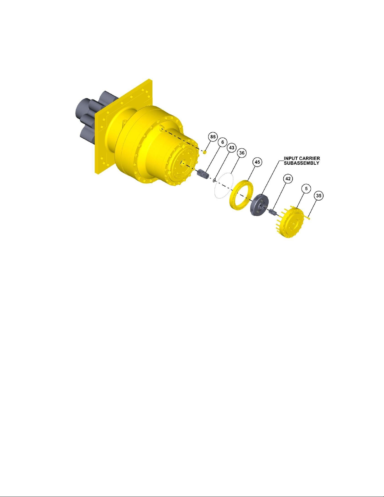
2.
Remove the two O-Ring Pipe Plugs (85) and drain the oil out of the gearbox by slightly tilting
the whole Unit.
NOTE: Record the condition and volume of the oil.
3.
Remove twenty Hex Bolts (35) from the Input Cover (5).
4.
Lift the Cover Subassembly off of the unit.
5.
Remove the O-Ring (36) out of the Unit and Discard it.
6.
Remove the Input Sun Gear (42) out of the Input Carrier Subassembly.
7.
Lift the Input Carrier Subassembly off of the unit.
8.
Remove the Ring Gear (45) out of the Unit.
9.
Remove the Thrust Washer (43) from the Intermediate Sun Gear (6).
10.
Remove the Intermediate Sun Gear (6) out of the unit.
Continued on Next Page

13
11.
Remove four Socket Head Bolts (12) with Washer (13) in X pattern.
12.
Remove sixteen Hex Bolts (11) with Washer (13) in X pattern.
13.
Lift the Input Cover (5) off of the Unit.
14.
Remove two Thrust Washers (9) from the Cover (5).
15.
Remove the O-Ring (8) from the groove of the Ring Gear (18) and discard the O-Ring.
16.
Lift the Intermediate Carrier Subassembly out of the Unit.
17.
Remove the Ring Gear (18) out of the Unit.
18.
Remove the O-Ring (25) from the groove of the Ring Gear (18) and discard the O-Ring.
Continued on Next Page
14
19.
Remove Intermediate Sun Gear (7) out of Intermediate Carrier Subassembly.
CAUTION: Safety glasses must be worn during these next step.
20.
Remove the Retaining Ring (26) from the external groove of the Sun Gear (7).
21.
Lift the Intermediate Carrier Subassembly out of the unit.
22.
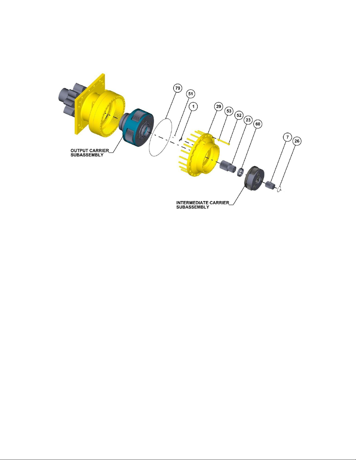
Remove the Spacer (60) from the Output Sun Gear (23).
23.
Remove the Output Sun Gear (23) from the Unit.
24.
Remove twenty Hex Bolts (52) with Washer (53) from the Spacer Housing (29).
25.
Lift the Spacer Housing (29) Subassembly off of the Unit.
26.
Remove the O-Ring (79) out of the Spacer Housing (29) and Discard the O-Ring.
27.
Remove five Spacers (1) from the Spacer Housing (29) by removing Screws (51) from the
Spacer Housing (29).
28.
Lift the Output Carrier Subassembly out of the Unit.
Continued on Next Page
15
29.
Remove the Ring Gear (24) from the Housing (32).
30.
Remove O-Ring (79) from the Housing (32) and Discard the O-Ring.
31.
Remove five Spacers (1) off of the Housing (32) by removing Screws (51).
NOTE: Refer page 23 for disassembly instruction of Output Pinion Subassembly.
32.
Turn over the Unit and remove the Output Pinion Subassembly out of the Housing (32) by
removing Hexagonal Bolts (48) with Flat Washers (49).
33.
Remove twelve Socket Head Bolts (59) from the Seal Carrier (19) and remove the Seal
Carrier (19) out of the Housing (32).
NOTE: Generally Seals should not be reused.
34.
Remove both Seals (57) from the Seal Carrier (19).
35.
Remove the O-Ring (20) from the groove of the Seal Carrier (19).
This concludes the Main Disassembly.

16
THIS PAGE
INTENTIONALLY
LEFT BLANK
17
Planetary Final Drive Service Manual
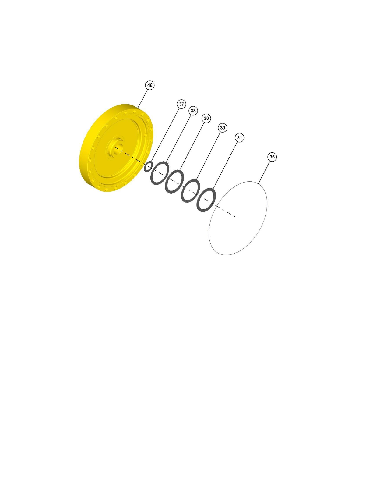
Cover Disassembly
1.
Remove the O-Ring (36) from groove in the Cover (46) and discard O-Ring.
2.
Remove Thrust Washers (31) from the Cover (46).
3.
Remove Thrust Bearing (39) from the Cover (46).
4.
Remove Thrust Washers (30) from the Cover (46).
5.
Remove Thrust Washers (38) from the Cover (46).
6.
Remove Thrust Washers (37) from pocket in the Cover (46).
This concludes the Cover Disassembly.

18
Planetary Final Drive Service Manual
Output Carrier Disassembly
1.
Place Output Carrier Subassembly with internal spline side down.
2.
Remove Adapter (17D) from the Carrier (17A) by removing twelve Bolts (17E) from the
Carrier (17A).
3.
Drive the Planet Shaft (17K) out of the Carrier (17A) planet shaft bore.(with punch through
small hole at spline end of Carrier (17A).)
4.
Slide Planet gear subassembly out of the Carrier (17A) window.
5.
Remove both the Bearings (17C) out of Planet Gear (17B).
6.
Repeat steps 3 to 5 for remaining three Planet Gears (17B) disassembly.
7.
Remove Thrust Plate (17G) out of Carrier (17A) by removing four Bolts (17J) from the
Carrier (17A).
8.
Remove the O-Ring (17H) from the external groove of the Thrust Plate (17G) and discard it.
This concludes the Output Carrier Disassembly.

19
Planetary Final Drive Service Manual
1st Stage Intermediate Carrier Disassembly
1.
Unbend the tang of Lock-Tanged Washer (2I) from the Bearing Nut (2H) and remove the
Bearing Nut (2H) from the Planet Shaft (2K).
2.
Remove Planet Shaft (2K) from the Carrier (2A).
3.
Remove Lock-Tanged Washer (2I) from the Carrier (2A) and discard it.
4.
Remove Lock Pin (2J) from slot of Carrier (2A).
5.
Slide out the Planet Gear Subassembly from the window of the Carrier (2A).
6.
Remove Thrust Washer (2F) from the window of the Carrier (2A).
7.
Remove both Bearing Cone (2C) from the bore of Planet Gear (2B).
8.
Remove both Bearing Cup (2D) from the bore of Planet Gear (2B).
9.
Remove Thrust Spacer (2E) from the bore of Planet Gear (2B).
CAUTION: Safety glasses must be worn during these next steps.
10.
Remove Retaining Ring (2G) from internal groove of the Planet Gear (2B).
11.
Repeat the steps 1 through 10 for the remaining two Planet Gears (2B).
This concludes the 1st Stage Intermediate Carrier Disassembly.

20
Planetary Final Drive Service Manual
2nd Stage Intermediate Carrier Disassembly
1.
Remove the three Retainer Plates (27) from the groove of the Carrier (4A) by removing
Socket Head Cap Screws (28) from the Internal Coupling (1H).
2.
Remove the Internal Coupling (1H) from the Carrier (4A).
3.
Remove the Thrust Spacer (1L) from the Internal Coupling (1H).
4.
Unbend the tang of Lock-Tanged Washer (4I) from the Bearing Nut (4H) and remove the
Bearing Nut (4H) from the Planet Shaft (4K).
5.
Remove Planet Shaft (4K) from the Carrier (4A).
6.
Remove Lock-Tanged Washer (4I) from the Carrier (4A) and discard it.
7.
Remove Lock Pin (4J) from slot of Carrier (4A).
8.
Slide out the Planet Gear Subassembly from the window of the Carrier (4A).
9.
Remove Thrust Washer (4G) from the window of the Carrier (4A).
10.
Remove both Bearing Cone (4C) from the bore of Planet Gear (4B).
11.
Remove both Bearing Cup (4D) from the bore of Planet Gear (4B).
12.
Remove Thrust Spacer (4F) from the bore of Planet Gear (4B).
Continued on Next Page

21
CAUTION: Safety glasses must be worn during these next steps.
13.
Remove Retaining Ring (4E) from internal groove of the Planet Gear (4B).
14.
Repeat the steps 4 through 13 for the remaining two Planet Gears (4B).
This concludes the 2nd Stage Intermediate Carrier Disassembly.

22
Planetary Final Drive Service Manual
Input Carrier Disassembly
1.
Unbend the tang of Lock-Tanged Washer (3H) from the Bearing Nut (3G) and remove the
Bearing Nut (3G) from the Planet Shaft (3E).
2.
Remove Planet Shaft (3E) from the Carrier (3A)
3.
Remove Lock-Tanged Washer (3H) from the Planet Shaft (3E) and discard it.
4.
Remove Lock Pin (3D) from slot of Carrier (3A).
5.
Slide out the Planet Gear Subassembly from the window of the Carrier (3A).
6.
Remove Thrust Washer (3B) from the window of the Carrier (3A).
NOTE: Bearing (3C) is a matched assembly and must be kept as a set unless they are to be
replaced.
7.
Remove both Bearing Cone (3C) from the bore of Planet Gear (3F).
NOTE: Skip steps 8 and 9 unless the bearing is to be replaced.
8.
Remove both Bearing Cup (3C) from the bore of Planet Gear (3F).
CAUTION: Safety glasses must be worn during these next steps.
9.
Remove Retaining Ring (3C) from internal groove of the Planet Gear (3F).
10.
Repeat the steps 1 through 9 for the remaining two Planet Gears (2B).
This concludes the Input Carrier Disassembly.

23
Planetary Final Drive Service Manual
Output Pinion Disassembly
1.
Remove the fourteen Hex Bolts (47) from Retainer Plate (40) through Spacer (41).
2.
Remove the Retainer Plate (40) from the Pinion.
3.
Remove the Spacer (41) from the Pinion.
4.
Use Bearing Puller and pull Bearing Carrier (33) with Bearing (56) and Seal (54) off the
splined end of Pinion
5.
Remove Bolts (48) and Washers (49) from Bearing Carrier (33) and lift off Seal Carrier (34).
6.
Press and remove the Spherical Roller Bearing (56) from the Bearing Carrier (33).
NOTE: Generally Seals should not be reused.
7.
Remove the Lip Seal (54) from the Seal Carrier (34)
This concludes the Output Pinion Disassembly.

24
ASSEMBLY

25
Planetary Final Drive Service Manual
Cover Subassembly
1.
Place Cover (46) with bore side up on the table.
2.
Grease and install Thrust Washer (38) onto the Cover (46).The grease should hold the
washer in place for assembly.
3.
Grease and install Thrust Washer (30) onto the Cover (46) on top of Thrust Washer (38).
4.
Grease and install Bearing (39) on top of Thrust Washer (30).
5.
Grease and install Thrust Washer (31) on top of Bearing (39).
6.
Grease and install Thrust Washer (37) onto the Cover (46).The grease should hold the
washer in place for assembly.
7.
Grease and install O-Ring (36) into the o-ring groove in cover (46). Insure that the O-Ring is
fully seated against the inner diameter.
This concludes the Cover Subassembly.

26
Planetary Final Drive Service Manual
Output Carrier Subassembly
1.
Place Output Carrier (17A) with internal spline side down.
2.
Grease and install O-Ring (17H) into the o-ring groove of Thrust Plate (17G).
3.
Install Thrust Plate (17G) into the bore of the Carrier (17A) with O-Ring side down. Align bolt
holes in Thrust Plate (17G) with bolt holes in Carrier (17A).
4.
Apply loctite-243 and Install Bolts (17J) into Carrier (17A) through Thrust Plate (17G).
Torque Bolts to 44ft-lbs.
5.
Press both the Bearings (17C) into the bore of the Planet Gear (17B) using press tool T216332 . Insure that the Bearings (17C) has seated fully against the bearing shoulder.
6.
Slide Planet Gear (17B), with part number facing up, into the window of the Carrier (17A).
Align the bores of Planet Gear with the planet shaft bore in Carrier (17A).
7.
Inspect the Planet Shaft (17K) for nicks and burs. Insure that the Planet Shaft hole and
Planet Shaft (17K) are free from debris, burrs, sharp corners. Align the flat of the Planet
Shaft (17K) with the counter bore of Carrier (17A). Lower the Planet Shaft (17K) into the
Carrier (17A) with the flange side up.
8.
Repeat steps above for the remaining Planet Gears (17B).
Continued on Next Page

27
9.
Roll all the Planet Gears (17B) to insure they roll freely.
10.
Install Adapter (17D) with flange side down onto the Carrier (17A).
11.
Apply Loctite-243 and install Hex Bolts (17E) into Carrier (17A) through Adapter
(17D).Torque bolts to 80ft-lbs
This concludes the Output Carrier Subassembly.

28
Planetary Final Drive Service Manual
1st Stage Intermediate Carrier Subassembly
1.
Place Carrier (2A) onto press table.
CAUTION: Safety glasses must be worn during these next steps.
2.
Place Planet Gear (2B) with part number up onto press table. Install Internal Retaining Ring
(2G) into the groove of Planet Gear (2B).
NOTE: In step below insure to install the spacer into the deepest bore side from the
retaining groove of the Planet Gear (2B).
3.
Install Spacer (2E) into the bore of the Planet Gear (2B) onto Retaining Ring (2G).
4.
Using Tool T-158152 Install both the Bearing Cups (2D) with wide face outside into bore of
the Planet Gear (2B). Insure that the Bearing Cups (2D) has seated fully against the
Retaining Ring (2G).
5.
Install Bearing Cone (2C) into Bearing Cup (2D) on both sides of the Planet Gear (2B).
6.
Apply grease and install Thrust Washer (2F) on Planet Shaft bore top side in Carrier (2A)
planet gear window.
Continued on Next Page

29
7.
Slide Planet Gear (2B) assembly into planet window of Carrier (2A) with Retaining Ring (2G)
towards internal spline.
8.
Align planet shaft bore in Planet Gear (2B) with Thrust Washer (2F) bore and Carrier (2A)
planet shaft bore
9.
Inspect the Planet Shaft (2K) for nicks and burs. Insure that the planet shaft hole and Planet
Shaft (2K) are free from debris, burrs, sharp corners. Start the Planet Shaft (2K) on the wide
side of the Carrier (2A). Install Planet Shaft (2K) through the large diameter in the Carrier
(2A) hole and through Planet Gear (2B) bearing inner race by aligning the lock pin slot in
both Carrier (2A) and Planet Shaft (2K).
10.
Install Dowel Pin (2J) into lock pin slot in Carrier (2A) and Planet Shaft (2K).
11.
Install tanged Lock Washer (2I) onto Planet Shaft (2K).
12.
Apply loctite-263 and install Bearing Nut (2H) onto Planet Shaft (2K) by using tool T-149933.
Tighten Bearing Nut (2H) and measure rolling torque of Planet Gear (2K) using a fish scale.
Torque Bearing Nut (2H) until 1.5 – 2 lbs of drag is achieved when rolling Planet Gear (2B).
13.
Bend tang into Bearing Nut (2H) slot.
14.
Repeat steps for the remaining Planet Gears (2B).
This concludes the 1st Stage Intermediate Carrier Subassembly.

30
Planetary Final Drive Service Manual
2nd Stage Intermediate Carrier Subassembly
1.
Place Carrier (4A) onto press table.
CAUTION: Safety glasses must be worn during these next steps.
2.
Place Planet Gear (4B) with part number up onto press table. Install Internal Retaining Ring
(4E) into the groove of Planet Gear (4B).
NOTE: In step below insure to install the Spacer (4F) into the deepest bore side from the
retaining groove of the Planet Gear (2B).
3.
Install Spacer (4F) into the bore of the Planet Gear (4B) onto Retaining Ring (4E).
4.
Use tool T-214147 and install both the Bearing Cups (4D) with wide face outside into bore of
the Planet Gear (4B). Insure that the Bearing Cups (4D) has seated fully against the
Retaining Ring (4E).
5.
Install Bearing Cone (4C) into Bearing Cup (4D) on both sides of the Planet Gear (4B).
6.
Apply grease and install Thrust Washer (4G) on planet shaft bore top side in Carrier (2A)
planet gear window.
Continued on Next Page

31
7.
Slide Planet Gear (4B) assembly into planet window of Carrier (2A) with Retaining Ring (4E)
towards internal spline.
8.
Align planet shaft bore in Planet Gear (4B) with Thrust Washer (4G) bore and Carrier (4A)
planet shaft bore
9.
Inspect the Planet Shaft (4K) for nicks and burs. Insure that the planet shaft hole and Planet
Shaft (2K) are free from debris, burrs, sharp corners. Start the Planet Shaft (4K) on the wide
side of the Carrier (4A). Install Planet Shaft (4K) through the large diameter in the Carrier
(4A) hole and through Planet Gear (4B) bearing inner race by aligning the lock pin slot in
both Carrier (4A) and Planet Shaft (4K).
10.
Install Dowel Pin (4J) into lock pin slot in Carrier (4A) and Planet Shaft (4K).
11.
Install tanged Lock Washer (4I) onto Planet Shaft (4K).
12.
Apply loctite-263 and install Bearing Nut (4H) onto Planet Shaft (4K) by using tool T-149933.
Tighten Bearing Nut (4H) and measure rolling torque of Planet Gear (4K) using a fish scale.
Torque Bearing Nut (4H) until 1.5 – 2 lbs of drag is achieved when rolling Planet Gear (4B).
13.
Bend tang into Bearing Nut (4H) slot.
14.
Repeat steps for the remaining Planet Gears (4B).
15.
Place Internal Coupling (1H) with small internal side down onto the table.
16.
Install Thrust Spacer (1L) with flange side up into the bore of Internal Coupling (1H).
17.
Lift the Carrier assembly using tapped holes in Planet Shaft (4K).
18.
Lower the carrier assembly into the Internal Coupling (1H). Insure the Carrier (4A) splines
engage with Internal Coupling (1H) splines.
19.
Install Retainer Plate (27) onto the flange of Internal Coupling (1H) with chamfer side
outwards. Align bolt holes of Retainer Plate (27) with bolt holes of Internal Coupling (1H).
20.
Apply Loctite-243 and install Socket Head Bolts (28) into the Internal Coupling (1H) through
Retainer Plate (27). Torque Socket Head Bolts (28) to 10-14 ft-lbs. Repeat steps for the
remaining Retainer Plates (27).
This concludes the 2nd Stage Intermediate Carrier Subassembly.

32
Planetary Final Drive Service Manual
Input Carrier Subassembly
1.
Place Carrier (3A) onto press table.
CAUTION: Safety glasses must be worn during these next steps.
NOTE: Bearing (3C) is a matched set and must stay as a set.
2.
Place Planet Gear (3F) with part number up onto press table. Install Internal Retaining Ring
(3C) into the groove of Planet Gear (3F).
3.
Use tool T-158149 and Install both the Bearing Cups (3C) with wide face outside into bore of
the Planet Gear (3F). Insure that the Bearing Cups (3C) has seated fully against the
Retaining Ring (3C).
4.
Install Bearing Cone (3C) into Bearing Cup (3C) on both sides of the Planet Gear (3F).
5.
Apply grease and install Thrust Washer (3B) on Planet Shaft bore top side in Carrier (3A)
planet gear window.
6.
Slide Planet Gear (3F) assembly into planet window of Carrier (3A) with part number facing
up.
Continued on Next Page

33
7.
Align planet shaft bore in Planet Gear (3F) with Thrust Washer (3B) bore and Carrier (3A)
planet shaft bore
8.
Inspect the Planet Shaft (3E) for nicks and burs. Insure that the planet shaft hole and Planet
Shaft (3E) are free from debris, burrs, sharp corners. Start the Planet Shaft (3E) on the wide
side of the Carrier (3A). Install Planet Shaft (3E) through the large diameter in the Carrier
(3A) hole and through Planet Gear (3F) bearing inner race by aligning the lock pin slot in
both Carrier (3A) and Planet Shaft (3E).
9.
Install Dowel Pin (3D) into lock pin slot in Carrier (3A) and Planet Shaft (3E).
10.
Install tanged Lock Washer (3H) onto Planet Shaft (3E).
11.
Apply loctite-263 and install Bearing Nut (3G) onto Planet Shaft (3E) by using tool T-223131.
Tighten Bearing Nut (3G) to 125 ft-lbs.
12.
Bend tang into Bearing Nut (3G) slot.
13.
Repeat steps for the remaining Planet Gears (3F).
This concludes the Input Carrier Subassembly.

Continued on Next Page
34
Planetary Final Drive Service Manual
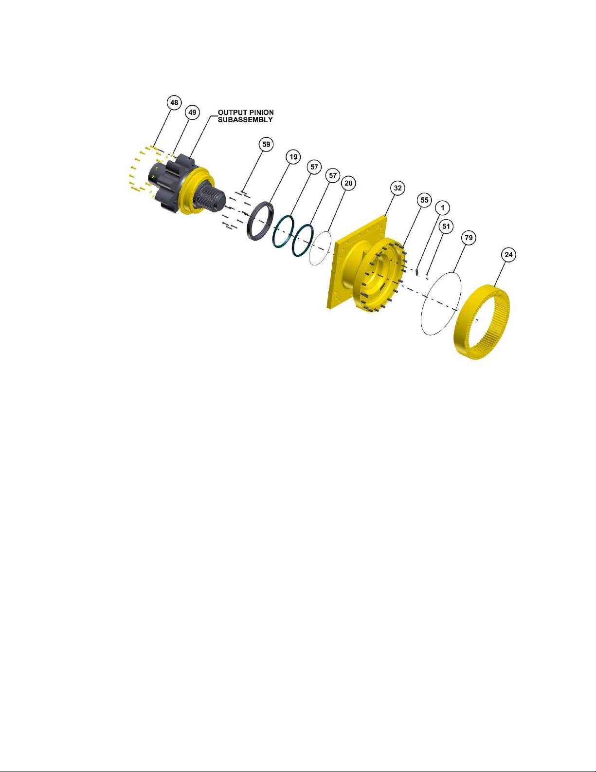
Output Pinion Subassembly
1.
Place Seal Carrier (19) with larger bore side up onto the press table.
2.
Spray the Seal Carrier (19) seal bore with alcohol, then wipe with a clean rag. Insure there is
no debris left in the bore.
3.
Spray the O.D. of the Lip Seal (57) with alcohol and wipe with a clean rag. Make sure not to
touch the O.D. of the Lip Seal (57) after it is clean and dry.
4.
Install the Lip Seal (57) into the Seal Carrier (19). Insure the seal is fully seated into the Seal
Carrier (19).
5.
Install the second Lip Seal (57) into the Seal Carrier (19). Insure the seal is fully seated into
the Seal Carrier (19).
6.
Pack the valley between Lip Seals (57) using grease.
7.
Grease and install O-Ring (20) into Seal Carrier (19).
8.
Install Seal Carrier (19) assembly into Housing (32) bore. Slowly push the Seal Carrier (19)
onto the Carrier (17A) by aligning bolt holes in Seal Carrier (19) with bolt holes in Housing
(32).

Continued on Next Page
35
9.
Apply Loctite-243 and install Socket Head Bolts (59) onto the Housing (1G) through the Seal
Carrier (19). Torque bolts (59) to 80-90 ft-lbs.
10.
Place Bearing (56) and Bearing Carrier (33) into oven at 200° F for 3 hours.
11.
Place Pinion with splines up.
12.
Spray the Seal Carrier (34) seal bore with alcohol, then wipe with a clean rag. Insure there is
no debris left in the bore.
13.
Spray the O.D. of the Lip Seal (54) with alcohol and wipe with a clean rag. Make sure not to
touch the O.D. of the Lip Seal (54) after it is clean and dry.
14.
Place and visually align the Lip Seal (54) into the Seal Carrier (34) seal bore.
15.
Press the Lip Seal (54) into the Seal Carrier (34) using the seal press tool. When the seal
press tool makes contact with the Seal Carrier (34) the seal is fully seated.
16.
Apply grease to the seal lip (54) and seal diameter of Pinion.
17.
Install Seal Carrier (34) assembly onto Pinion shaft. Slowly push the Seal Carrier (34) onto
the larger diameter of the Shaft near gear teeth.
18.
Apply Loctite 518 to Seal Carrier (34) mounting surface.
19.
Remove Bearing (56) from oven and install Bearing (56) into the Pinion. Insure that the
Bearing (56) is fully seated against the Pinion bearing shoulder.
20.
Remove Bearing Carrier (33) from oven. Install Bearing Carrier (33) onto the Bearing (56)
after the bearing has cooled sufficiently. with flange side down. Insure the Bearing Carrier
(33) has seated completely. Allow system to cool.
21.
Install Spacer (41) onto Bearing (56).
22.
Install both halves of Retainer Plate (40) onto groove of Pinion and onto Spacer (41) by
aligning bolt holes in Retainer Plate (40) with Spacer (41).
23.
Apply Loctite-243 and install Socket Head Bolts (47) into Spacer (41) through Retainer Plate
(40).Torque bolts to 100 ft-lbs.
24.
Turn over the pinion assembly and apply Loctite-518 to Bearing Carrier (33) mounting
surface again.
25.
Align bolt holes in Seal Carrier (34) with Bearing Carrier (33) bolt holes.
26.
Apply Loctite-243 and install Hex Bolts (48) through Washer (49) into Bearing Carrier (33)
through the Seal Carrier (34). Torque Bolts to 78-92 ft-lbs.
27.
Lift and position the Pinion assembly over Housing (32) bore. Carefully lower the Pinion
assembly into Housing (32) bore by aligning the splines in Pinion with Carrier 17(A) splines.
Also align the Bearing Carrier (33) bolt holes in Pinion assembly with Housing (32) bolt
holes.

36
28.
Insure the Bearing Carrier (33) in Pinion assembly has fully seated onto Housing (32).
29.
Apply Loctite-243 and install Hex Bolts (48) through Washer (49) into Housing (32) through
the Bearing Carrier (33). Torque Bolts to 78-92 ft-lbs.
This concludes the Output Pinion Subassembly.

37
Planetary Final Drive Service Manual
Main Assembly
1.
Place Housing (32) flange side down onto assembly fixture. Install bolts into fixture through
Housing (32) flange.
2.
Spray the Housing (32) bushing bore with alcohol, then wipe with a clean rag. Insure there is
no debris left in the bore.
3.
Spray the component internal surfaces with RP oil. Install five Spacer (1) into the spacer
slots in Housing (32).
4.
Apply Loctite-243 and install Flat Head Hex Bolts (51) into the Housing (32) through Spacer
(1). Torque to 270-280 in-lbs
5.
Using thread sealant install Grease Fittings (76) onto Housing (32). Torque to 20 ft-lbs.
6.
Lower Output Carrier Subassembly into Housing (32) bore with internal splines side
down.Insure not to damage the Bushing (21) while lowering the Carrier Subassembly into
Housing (32).
Continued on Next Page

38
NOTE: Insure not to Grease O-Ring (79) in step below.
7.
Install O-Ring (79) onto the Housing (32) o-ring groove.
8.
Lower Ring Gear (24) onto the Housing (32) by aligning the Ring Gear (24) teeth with the
planet gear teeth of the Output Carrier Subassembly. Insure that the Ring Gear (24)
dowelpin holes are aligned with the dowel pins in housing. Insure that the Ring Gear (24) is
seated against the Housing (32).
9.
Spray the internal components with RP oil.
10.
Place Spacer Housing (29) with flange side up onto the table.
11.
Install Spacer (1) into the spacer slots in Spacer Housing (29).
12.
Apply Loctite-243 and install Flat Head Hex Bolts (51) into the Spacer Housing (29) through
Spacer (1). Torque to 270-280 in-lbs.
13.
Spray the Spacer Housing (29) bushing bore in Spacer Housing (29) with alcohol, then wipe
with a clean rag. Insure there is no debris left in the bore.
14.
Grease and install O-Ring (79) onto the Spacer Housing (29) o-ring groove.
Continued on Next Page

39
15.
Lower Spacer Housing (29) onto Ring Gear (24) with flange side down. Align bolts holes in
Spacer Housing (29) with Ring Gear(24) bolt holes. Insure the Spacer Housing (29) has
seated against Ring Gear (24).
16.
Install four Hex Bolts (52) through Washer (53) into the Spacer Housing (29). Torque Bolts
(52) to 680 ft-lbs.
17.
Install O-Ring Plugs (85) into pipe plug holes in Spacer Housing (29).Torque Pliugs to 170192 ft-lbs.
NOTE: Use O-Ring (25) to leak test in the step below for leak test adapter plate.
18.
Install leak test adapter plate tool T-222390 onto the Spacer Housing (29).
19.
Perform air leak test and record the results in QDR.
20.
Remove test adapter plate T-222390.
21.
Apply loctite-243 and install rest of Hex Bolts (52) through Washer (53) into the Spacer
Housing (29). Torque Bolts (52) to 680 ft-lbs.
Continued on Next Page

40
22.
Lower Sun Gear (23) with spline side up into the output planet gear mesh. Insure Sun Gear
(23) is engaged with planet gears of Output Carrier Subassembly..
23.
Install Spacer (60) onto the Sun gear (23).
24.
Lower Intermediate Carrier Subassembly with internal coupling side down onto sun gear
(23). Insure that the internal coupling splines and the Sun Gear (23) splines are engaged
and Thrust Washer (1L) has seated into bore of Sun Gear (23).
25.
Grease and install O-Ring (25) onto the Ring Gear (18) o-ring groove.
26.
Lower Ring Gear (18) onto the Spacer Housing (29). Align the Ring Gear (18) teeth with the
planet gear teeth of the Intermediate Carrier Subassembly (4). Insure that the reamed
shoulder bolt holes in Ring Gear (18) are aligned with the appropriate tapped holes in
Spacer Housing (29). Insure that the Ring Gear (18) is seated against the Spacer Housing
(29).
CAUTION: Safety glasses must be worn during these next steps.
27.
Install Retaining Ring (26) onto external retaining ring groove of Sun Gear (7).
28.
Install Sun Gear (7) with spline side up into the intermediate planet gear mesh.
Continued on Next Page

41
29.
Lower Intermediate Carrier subassembly (2) into the Ring Gear (18). Rotate the planet
gears slowly until the planet gear drops into engagement with Ring Gear (18) teeth and
Carrier splines with Sun Gear (7) splines.
30.
Install Sun Gear (6) into the planet gear mesh.
31.
Spray the internal components with RP oil.
32.
Grease and install O-Ring (8) into the o-ring groove in Ring Gear (18). Insure that the ORing (8) is fully seated against the inner diameter.
33.
Grease and install two Thrust Washers (9) into the Cover (5). The grease should hold the
Washers (9) in place for assembly.
34.
Install the Cover (5) onto the Ring Gear (18). Align the bolt holes in the Cover (5) with the
holes in the Ring Gear (18).
35.
Install cover Bolts (11) through lock Washer (13) through Cover (5) bolt holes.
36.
Torque Bolts (11) using calibrated torque gun in star pattern per standard bolt circle torque
procedure. Torque Bolts (11) to 300-350 ft-lbs.
37.
Install Shoulder Bolts (12) through Washer (13) through Cover (5) bolt holes. Torque Bolts
(12) to 170-200 ft-lbs.
Continued on Next Page

42
38.
Grease and install Thrust Washer (43) onto the Intermediate Sun Gear (6). The grease
should hold the Washer (43) in place for assembly.
39.
Grease and install O-Ring (36) onto the Cover (5). Insure that the O-Ring (26) is fully seated.
40.
Install Input Carrier Subassembly (3). Insure Input Carrier splines engage with Sun Gear (6)
splines.
41.
Install Ring Gear (45) onto the Cover (5). Align bolt holes in Ring Gear (45) with the Cover
(5) bolt holes. Insure that the Ring Gear (45) is seated against the Cover (5).
42.
Install Sun Gear (42) into the mesh with gear side down. Insure the Sun Gear (42) engages
into the mesh with input planet gears.
NOTE: Insure the Input Sun Gear (42) aligns with the bore of Thrust Washer (43).
43.
Install the Input Cover Subassembly onto the Ring Gear (45). Align the bolt holes in the
Cover (46) with the holes in the Ring Gear (45).
44.
Apply loclite-243 and Install Hex Bolts (35) on Cover (46) through Ring Gear (45) using
calibrated torque gun in star pattern per standard bolt circle torque procedure, and Torque
Bolts (35) to 80-100 ft-lbs.
45.
The unit should now be leak and roll checked as per instructions on page 5 & 6.
This concludes the Main Assembly.

43
Planetary Final Drive Service Manual
Assembly Drawing

44
Planetary Final Drive Repair Instructions
Parts List
Number
Qty
Description
51
20
FLT HD HEX BOLT
53
20
WASHER
17G 1
THRUST PLUG
17K 4
PLANET SHAFT
1 10
SPACER(SPECIAL)
33 1
BEARING CARRIER
34 1
SEAL CARRIER
23 1
SUN GEAR
17B 4
PLANET GEAR
24 1
RING GEAR
40 1
RETAINER PLATE
41 1
SPACER
17D 1
THRUST HUB
29 1
SPACER HOUSING
32 1
MAIN HOUSING
17A 1
CARRIER
3A 1
CARRIER
2A 1
CARRIER
4A 1
CARRIER
3F 3
PLANET GEAR
42 1
SUN GEAR
19 1
SEAL CARRIER
45 1
RING GEAR
2B 3
PLANET GEAR
6 1
SUN GEAR
7 1
SUN GEAR
18 1
RING GEAR
3B43 4
THRUST WASHER
38 1
THRUST WASHER
2J3D 9
LOCK PIN
3E 3
PLANET SHAFT
3C 3
TAPPERED BEARING
9 2
THRUST WASHER
5 1
INPUT COVER
25 1
O-RING
37 1
THRUST WASHER
2K 3
PLANET SHAFT
2C 6
BEARING CUP

45
Number
Qty
Description
2D 6
BEARING CONE
2E 3
THRUST WASHER
4K 3
PLANET SHAFT
4C 6
BEARING CUP
4D 6
BEARING CONE
4F 3
THRUST WASHER
2F4G 6
THRUST WASHER
27 3
RETAINER PLATE
1L 1
THRUST SPACER
39 1
THRUST BEARING
30 1
THRUST WASHER
46 1
INPUT COVER
36 2
O-RING
17C 8
ROLLER BEARING
21 1
STEEL BUSHING
56 1
ROLLER BEARING
22 1
STEEL BUSHING
60 1
SPACER
15 1
ID PLATE
54 1
LIP SEAL
57 2
LIP SEAL
26 1
RETAINIGN RING
4E 3
RETAINIGN RING
2G 3
RETAINIGN RING
17H 1
O-RING
55
20
DOWEL PIN
35
20
HEX BOLT
52
20
HEX BOLT
17E
12
HEX BOLT
11
16
HEX BOLT
12 4
SHDR BOLT
16 2
SCREW
47
14
SOCKET HEAD BOLT
17J 4
SOCKET HEAD BOLT
59
12
SOCKET HEAD BOLT
28 6
SOCKET HEAD BOLT
48
32
HEX BOLT
8 1
O-RING
20 1
O-RING
79 2
O-RING
44 2
PIPE PLUG
14 2
PIPE PLUG

46
85 2
PIPE PLUG
4B 3
PLANET GEAR
1H 1
COUPLING
13
20
LOCK WASHER
3H 3
TANGED LOCK WASHER
2I4I 6
TANGED LOCK WASHER
49
32
FLAT WASHER
31 1
THRUST WASHER
3G 3
BEARING NUT
2H4H 6
BEARING NUT
76 2
GREASE FITTING
47
Planetary Final Drive Repair Instructions
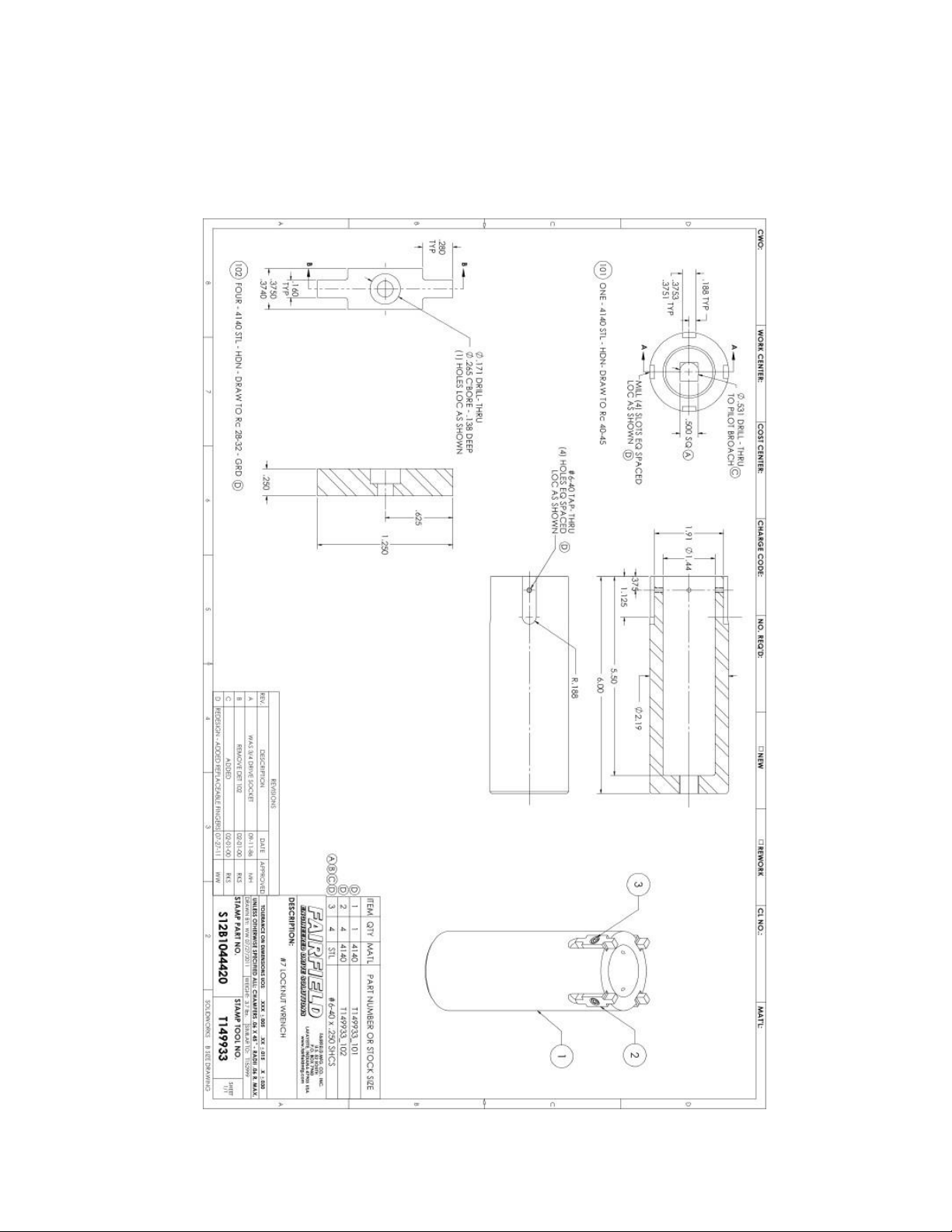
Assembly Tools
T149933 – LOCKNUT WRENCH

48
T158149 – BEARING CUP PRESS TOOL

49
T170237 – LEAK TEST ADAPTOR

50
T214147 – ASSEMBLY PRESSING TOOL

51
T216332 – ASSEMBLY PRESSING TOOL

52
T222390 – LEAK TEST ADAPTER PLATE

53
T223131 – LOCKNUT WRENCH

54
T223989 – ROLL CHECKING TOOL

55
Planetary Final Drive Repair Instructions
Contact Information
With more than 100 years of experience, Fairfield Manufacturing
Co. Inc. has become the largest U.S. non-captive producer of
gears, custom gear assemblies, planetary final drives and related
gear products. Fairfield Manufacturing Co. Inc., headquartered in
Lafayette, Indiana USA, is distinguished by our extensive design,
manufacturing and applications engineering capabilities.
Our 500,000 square foot plant is a modern, fully equipped
manufacturing facility that includes a full service heat treat
department.
Our philosophy of synchronous engineering is a partnership that
matches our best and brightest people with your people to evaluate
your unique requirements, and develop products and assemblies
that meet your needs.
For more information, contact Fairfield Manufacturing Co Inc. today.
Mailing Address Dana Incorporated
Off-Highway Drive and Motion Technologies
2400 Sagamore Parkway South / P.O. Box 7940
Lafayette, IN 47903 USA
Shipping Address 2309 Concord Road
Lafayette, IN 47909
Fax Main (765) 772-4001
Applications Engineering (765) 772-4011
Sales and Service (765) 772-4010
E-mail Applications Engineering apps@fairfieldmfg.com
Sales
sales@fairfieldmfg.com
Website
www.grazianofairfield.com

56
Dana Incorporated
Off-Highway Drive and Motion Technologies
2400 Sagamore Parkway South / P.O. Box 7940
Lafayette, IN 47903 USA
765-772-4000
www.grazianofairfield.com
 Loading...