

DANA Spicer Torque-Hub C017A1 Service Manual
Rev. 6/6/16
Torque-Hub® Planetary Final Drive
C017A1 Service Manual

2
Fairfield Manufacturing Co. Inc., Lafayette, IN, is now a part of Dana Incorporated
While every precaution has been taken in the preparation of this document, Fairfield Manufacturing Co. Inc.
assumes no liability with respect to the use of the documentation described herein, or for any act or omission
of Fairfield Manufacturing Co. Inc. concerning this documentation. Torque-Hub® is a registered trademark
of Fairfield Manufacturing Co. Inc.
Features and specifications are subject to change without notice.

3
Planetary Final Drive Service Manual
Table of Contents
Introduction.................................................................................................................................................... 4
Park Brake Test ............................................................................................................................................ 5
Service Brake Test ........................................................................................................................................ 6
Roll and Leak Test ........................................................................................................................................ 7
Tightening and Torquing Bolts ...................................................................................................................... 9
Lubrication Information ................................................................................................................................ 10
Park Brake Disassembly ............................................................................................................................. 12
Main Disassembly ....................................................................................................................................... 13
Service Brake Disassembly ........................................................................................................................ 16
Cover Disassembly ..................................................................................................................................... 18
Input Carrier Disassembly ........................................................................................................................... 19
Input Carrier Subassembly.......................................................................................................................... 22
Cover Subassembly .................................................................................................................................... 23
Main Assembly ............................................................................................................................................ 24
Service Brake Subassembly ....................................................................................................................... 25
Park Brake Subassembly ............................................................................................................................ 31
Assembly Drawing....................................................................................................................................... 32
Parts List ..................................................................................................................................................... 33
Service Kits ................................................................................................................................................. 34
Assembly Tools ........................................................................................................................................... 35
Contact Information ..................................................................................................................................... 43

4
Introduction
This manual is a step-by-step guide to the disassembly and assembly
of the specific Torque-Hub® family of units shown on the cover. It is
designed for the customer or mechanic who is repairing this particular
Torque-Hub® model.
Users of this manual should note that each part mentioned is followed
by an identification number enclosed in parentheses. These part
numbers may be referred to in the Parts List and Assembly Drawing
sections of this manual.
Specialized tools used to assemble this unit are noted in the assembly
procedures and diagrammed in the Assembly Tools section.
Users should familiarize themselves with the procedures for brake
test, roll and leak test, as well as bolt tightening and torquing found on
the following pages before starting any repairs.
Standard safety practices should be followed during the disassembly
and assembly procedures described. Safety glasses and safety shoes
should be worn, and heavy, heat resistant gloves should be used
when handling heated components. Be especially alert when you see
the word CAUTION. This indicates that a particular operation could
cause personal injury if not performed properly or if certain safety
procedures are not followed. The word NOTE is used to bring attention
to certain procedures or helpful hints that will aid in the disassembly
and assembly process.

5
Park Brake Test
The Park Brake Test 1) Install Roll and Leak Test fixture into coupling and onto
spindle. Install an SAE J1926-1 #6 (9/16-18) O-ring fitting into
the “Park” port on the spindle.
2) Apply 25 in-lbs. torque to the input while slowly increasing the
pressure to the “Park” port on the spindle, until the brake slips.
Record the pressure. The “just release pressure” should be
between 150-181 psi. Increase the pressure to 198 psi. The
gearbox should roll freely. Increase the pressure in this port to
1500psi and hold for one minute. If the brake does not leak or
lose pressure, the unit passed the test. If the brake loses
pressure, the brake must be repaired. See procedures in this
manual for dis-assembly and assembly procedures.

Service Brake Test
The Service Brake Test 1) Install Roll and Leak Test fixture into coupling and onto spindle.
Install an SAE J1926-1 #6 (9/16-18) O-ring fitting into the “Park”
and “Service” ports on the spindle. Release the Park brake by
applying 1500 psi to this port.
2) Apply 25 in-lbs. torque to the input while slowly increasing the
pressure to the “Service” port on the spindle, until the brake stops
the hub. Increase the pressure in this port to 2,100 psi and hold
for one minute. If the brake does not leak or lose pressure, the unit
passed the test. If the brake loses pressure, the brake must be
repaired. See procedures in this manual for dis-assembly and
assembly procedures.
NOTE: FAILURE TO PERFORM THIS TEST MAY RESULT IN
DAMAGED OR INEFFECTIVE BRAKE PARTS.
6
7
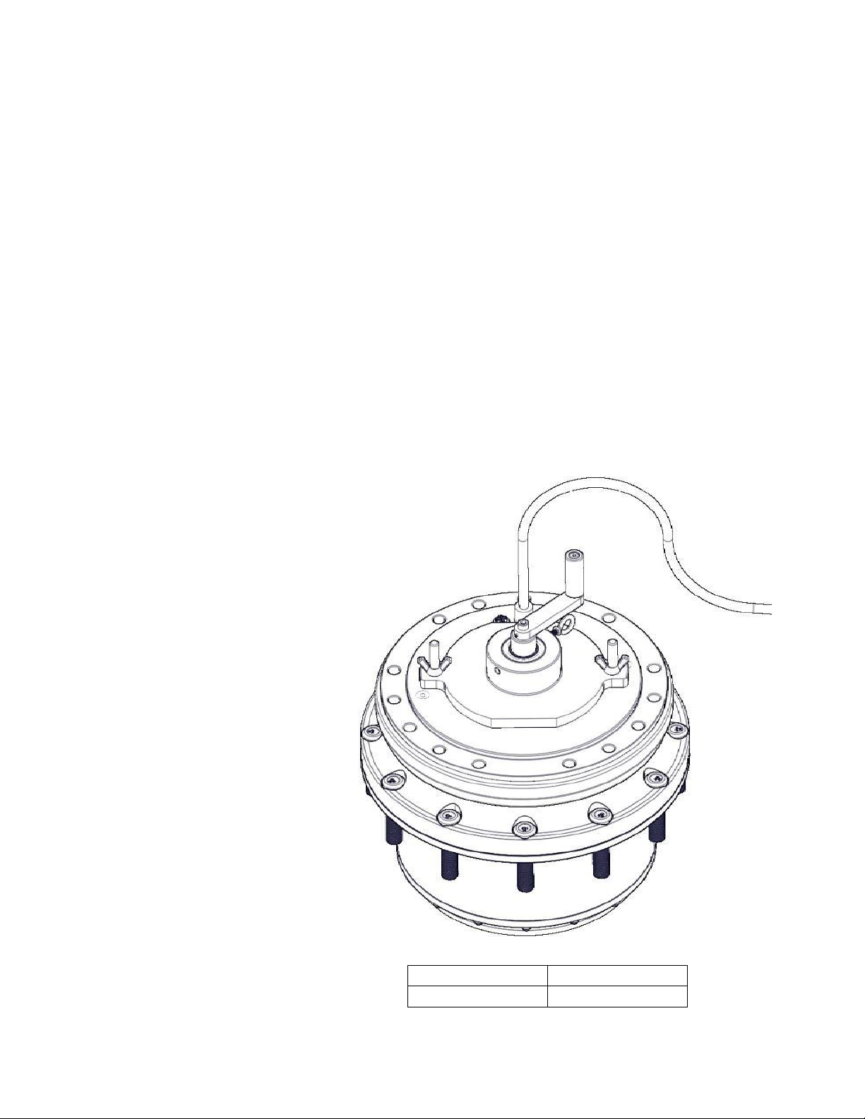
Roll and Leak Test
Torque-Hub® units should always be roll and leak tested before
disassembly (if possible) and after assembly to make sure the unit’s
gears, bearings, and seals are working properly. The following
information briefly outlines what to look for when performing these
tests.
The Roll Test The purpose of the roll test is to determine if the unit’s gears are
rotating consistently, easily and properly. Install Roll and Leak Test
fixture into coupling and onto spindle. Install an SAE J1926-1 #6 (9/16-
18) O-ring fitting into the “Park” port on the spindle. Release the Park
brake by applying 1500 psi to this port. Apply constant rotational force
to the input of the gearbox. If more drag is felt in the gears only at
certain points, then the gears are not rolling consistently and easily
and should be examined for improper installation or defects. Some
gear packages roll with more difficulty than others. Do not be
concerned if the gears in the unit seem to roll hard as long as they roll
with consistency. Rotate the gearbox both clockwise and
counterclockwise six revolutions.
Model Code
Roll Test Tool
C017A1
T-226231
8
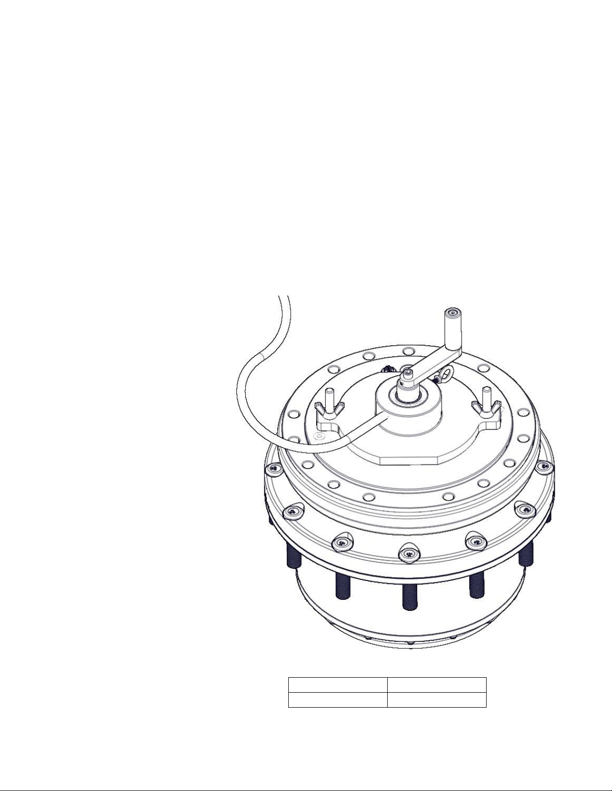
The Leak Test The purpose of a leak test is to make sure the unit is airtight. To
perform a leak test use the leak test fixture from the table below. If the
tool is not available, the gearbox must be sealed to perform the test.
This can be accomplished by replacing one of the oil plugs in the cover
with an air chuck. DO NOT EXCEED 10 PSI PRESSURE DURING
THE LEAK TEST. Higher pressure will create a false sealing effect in
assemblies with lip-seals. The unit has a leak if the pressure gauge
reading on your leak check fitting starts to fall after the gearbox has
been pressurized and allowed to equalize. Leaks will most likely occur
at the pipe plugs, the main seal or wherever O-rings or gaskets are
located. The exact location of a leak can usually be detected by
brushing a soap and water solution around the main seal and where
the O-rings or gaskets meet on the exterior of the unit and then
checking for air bubbles. If a leak is detected in a seal, O-ring, or
gasket, the part must be replaced and the unit rechecked. Leak test at
10 psi for 20 minutes. If the assembly has brakes do not plug any of
the brake ports as this may be an alternate leak path. Also if the
assembly does not have a brake that port needs to be sealed as there
are not brake seals.
Model Code
Leak Test Tool
C017A1
T-226231

9
Tightening and Torquing Bolts
If an air impact wrench is used to tighten bolts, extreme care should
be taken to ensure the bolts are not tightened beyond their specified
torque. The following steps describe how to tighten and torque bolts
or socket head cap screws in a bolt circle.
1)
Tighten (but do not torque) bolt “A” until snug.
2)
Go to the opposite side of the bolt circle and tighten bolt “B” until
equally snug.
3)
Crisscross around the bolt circle and tighten the remaining bolts.
4)
Use a torque wrench to apply the specified torque to bolt “A”.
5)
Using the same sequence, crisscross around the bolt circle and
apply an equal torque to the remaining bolts.
10
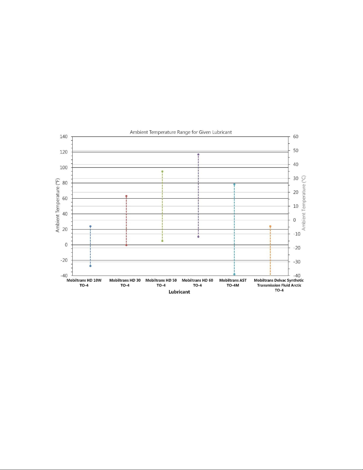
Lubrication Information
General Properties The lubricant used in most Torque-Hub® drives should be petroleum
based gear fluid containing anti-oxidation, anti-foaming and extreme
pressure additives. The lubricant should have a minimum viscosity
index of 95 cst and maintain a minimum viscosity of 40 cst under
normal operating conditions. Some applications require special
considerations; consult the machine manufacturer and Fairfield for
more additional information.
The table below lists the recommended lubricants for various ambient
operating temperatures. Contact Fairfield for other options.
Maintenance An initial oil change should be made after the first 50 hours of
operation. Subsequent oil changes should be made at 1,000 hour
intervals or annually, whichever comes first.
Oil temperatures should be not higher than 200°F for continuous
operation, and no higher than 225°F for intermittent operation. For
special applications, high horsepower, high speeds or wide
temperature changes, please consult Fairfield.
Oil Fill Level When the Torque-Hub® unit is mounted horizontally, unless otherwise
specified, the gearbox should be filled with oil to the “fill-line”, which is
below center, or approximately 50 oz. (1479 cc) with brakes, and 56
oz. (21656 cc) without brakes. Actual oil volume will vary with motor
make and model. Vertically mounted Torque-Hub® units may require
special lubrication procedures. Please contact Fairfield for vertically
mounted applications.

11
DISASSEMBLY
12
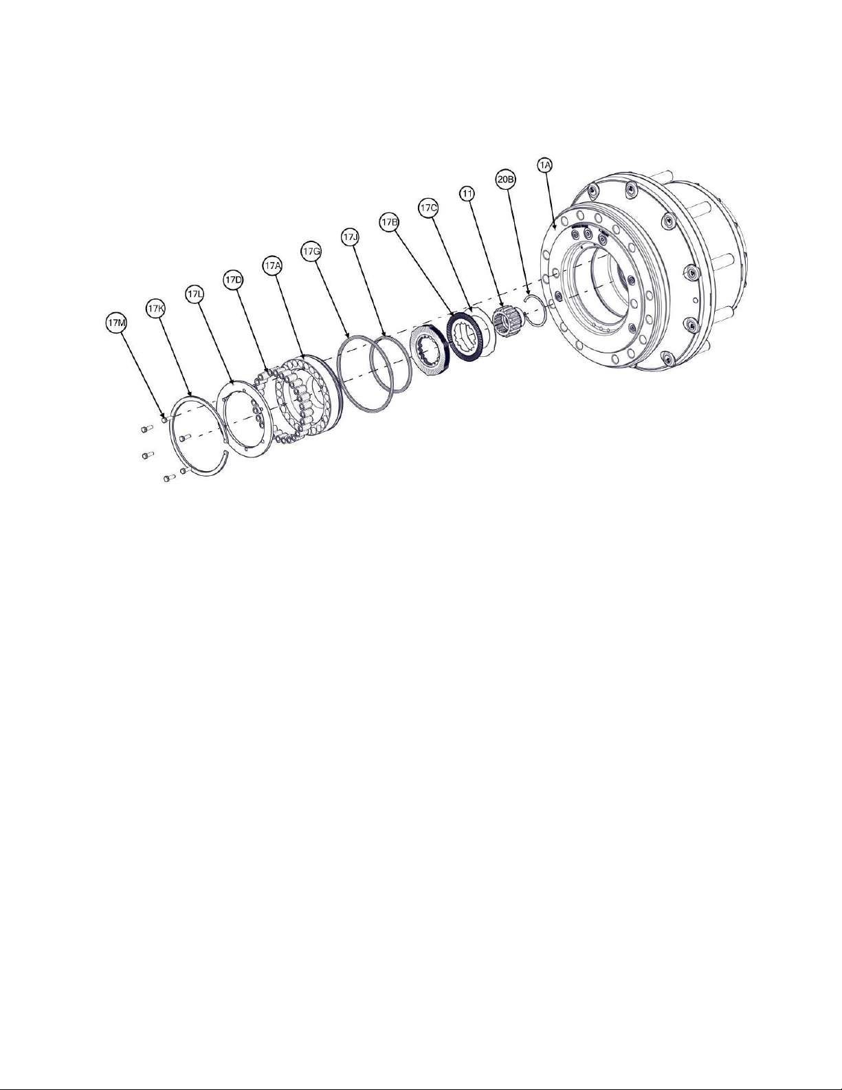
Park Brake Disassembly
1)
Place the gearbox flange up on the bench. Install M6-1.0x20 Bolts (17M) thru the Pressure Plate (17L)
into the Piston (17A). Tighten the bolts evenly to compress the Brake Springs (17D).
2)
Carefully remove the Retaining Ring (17K). Remove the Piston (17A), this may be done by applying
low air pressure to the “PARK” pressure port on the Spindle (1A).
3)
Remove the Quad-rings (17G) and (17J) from the grooves in the Spindle (1A) bore.
4)
Remove the Brake Stators (17C) and Brake Rotors (17B).
5)
Remove the M6-1.0x20 Bolts (17M) from the Piston (17A) slowly and evenly to relieve the spring
pressure. Remove the Pressure Plate (17L) and Springs (17D).
6)
Remove the Coupling (11) with the Retaining Rings (20B) and (20C).
This concludes the Brake Disassembly.
13
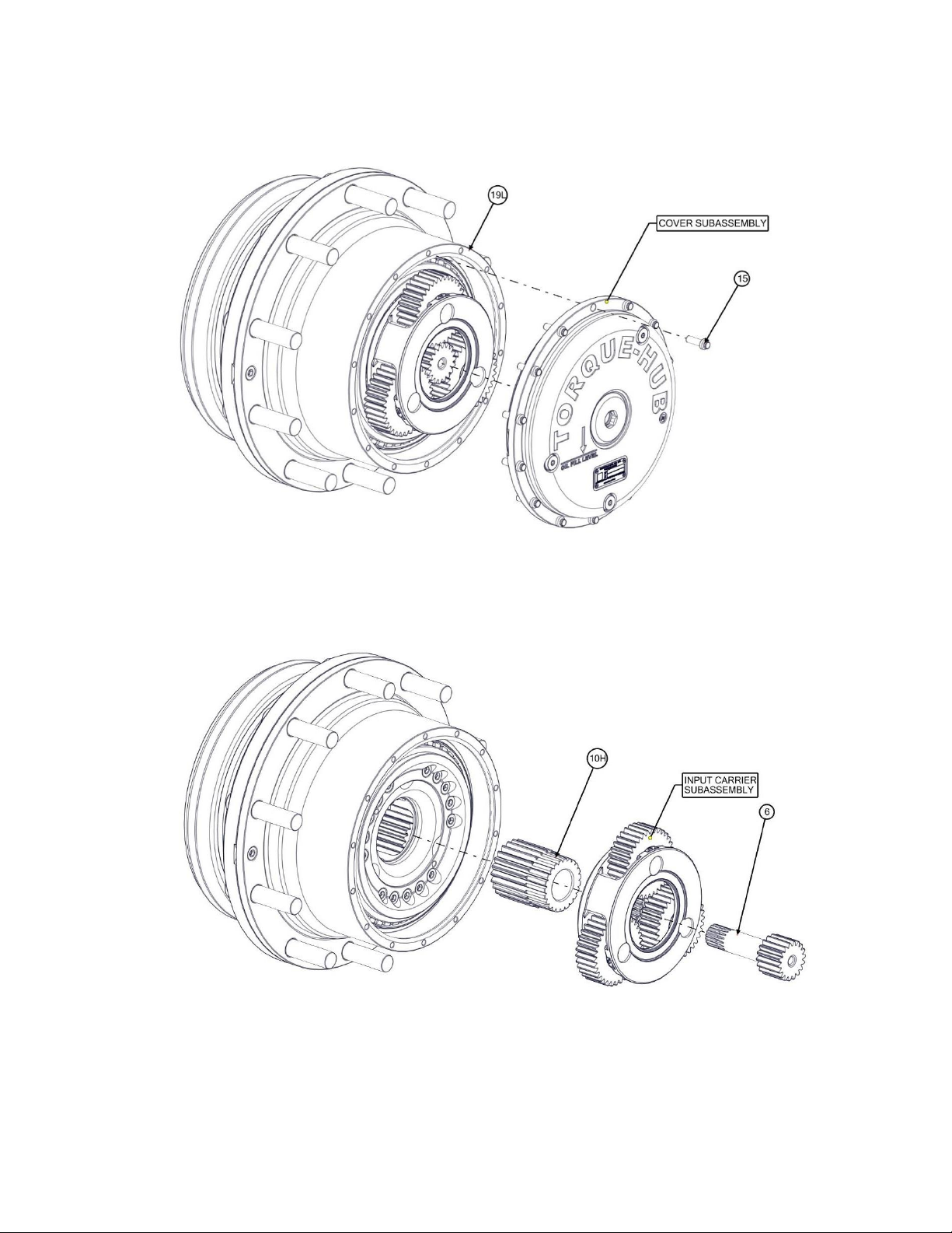
Main Disassembly
1)
Remove Oil Plugs (6H) and drain the oil. Notice the condition of the oil and the volume.
2)
Remove the Bolts (15) from the housing.
3)
Remove the Sun Gear (6).
4)
Remove the Input Carrier Sub-Assembly.
5)
Remove the Sun Gear (10H).
Continued on Next Page
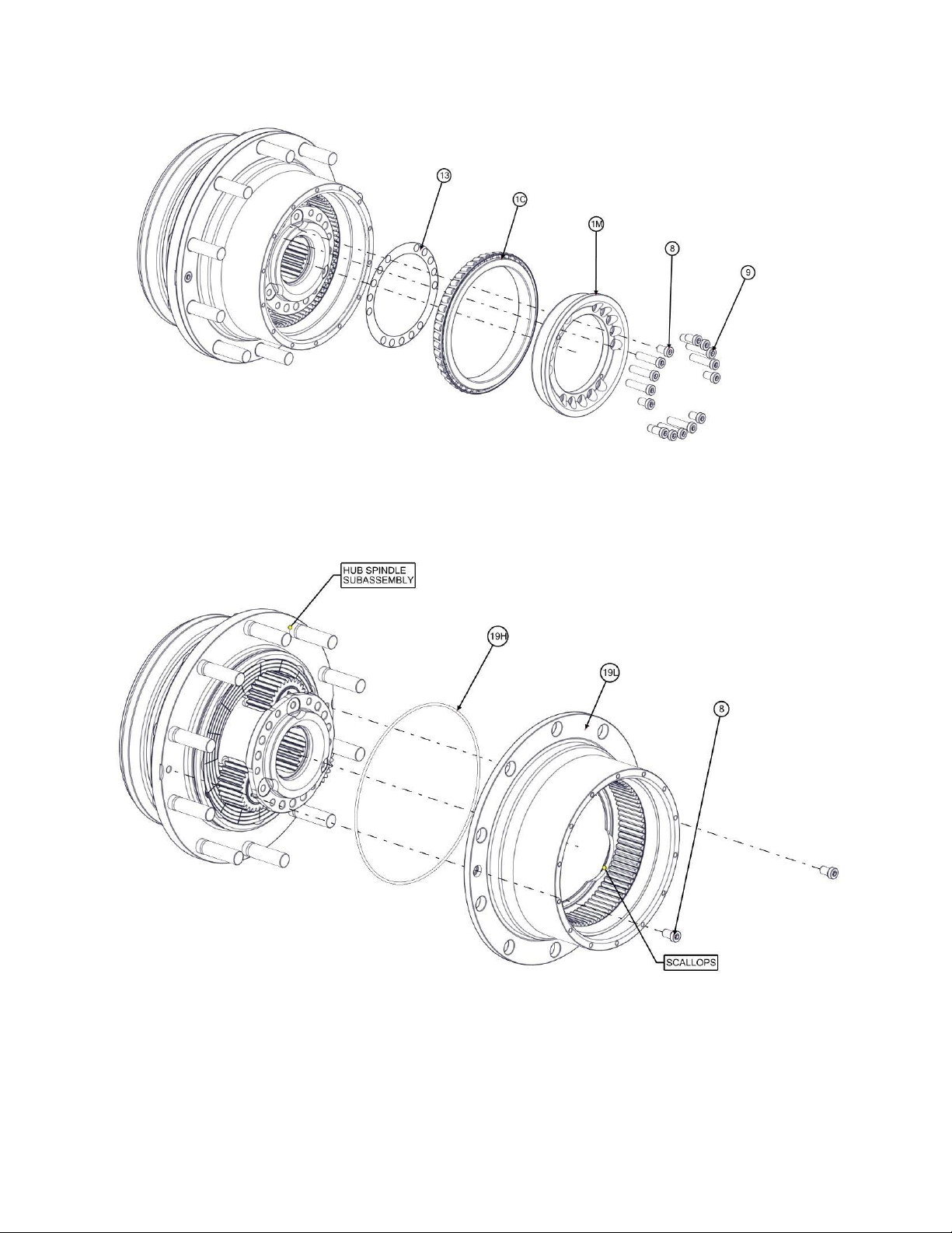
14
6)
Remove Socket Head Bolts (8) and (9). There are two different lengths.
7)
Remove the Bearing Carrier (1M) with the Bearing Cone (1C).
8)
Remove the Shims (13) from the Spindle (1A). Note: the shims can be very sharp.
9)
Remove the Socket Head Screws (8).
10)
Note: The Ring Gear (19L) will need to be rotated to line up the scallops in the brake flange with
the Planet Gears then remove the Ring Gear.
11)
Remove and discard the O-ring (19H) from the groove in the Housing (1G).
Continued on Next Page
 Loading...