

DANA Spicer Drive Axles Service Manual

Spicer
®
Drive Axles
Service Manual
AXSM0029
September 2007
General Information
General Information
The description, testing procedures, and specifications contained in this service publication were current at the time of printing.
Dana reserves the right to discontinue or modify its models and/or procedures and to change specifications at any time without
notice and without incurring obligation.
The recommendations of the vehicle manufacturer should be considered as the primary source of service information regarding
this Spicer product. This manual is intended to be used as a supplement to such information.
Any reference to brand names in this publication is made simply as an example of the types of tools and materials recommended
for use and, as such, should not be considered as an endorsement. Equivalents, if available, may be used.
IMPORTANT NOTICE
This symbol is used throughout this
publication to call your attention to areas
in which carelessness or failure to follow
specific procedures may result in
personal injury and/or component
malfunction or damage.
Anyone departing from the
instructions contained in this
publication through procedures
used or choice of tools, materials
and parts may jeopardize his personal
safety and/or the safety of the vehicle user.
Always use genuine Spicer replacement parts.
WARNINGS: Used in areas
where failure to follow listed
procedures creates a high
probability of personal injury
to the servicing technician.
CAUTIONS: Used in areas
where failure to
procedures may cause personal
injury due to component
damage or subsequent malfunction.
follow listed

Table of Contents
Electric Shift System
Introduction
Electric Shift System . . . . . . . . . . . . . . . . . . . . . . . . . 1
Mechanical Operation . . . . . . . . . . . . . . . . . . . . . . . . 2
Troubleshooting . . . . . . . . . . . . . . . . . . . . . . . . . . . . 5
Shift Unit Removal/Disassembly
Remove Shift Unit . . . . . . . . . . . . . . . . . . . . . . . . . . . 8
Remove Slider Block . . . . . . . . . . . . . . . . . . . . . . . . . 8
Remove Circuit Board and Motor . . . . . . . . . . . . . . . 9
Remove Gear and Cam Pins . . . . . . . . . . . . . . . . . . 10
Cleaning. . . . . . . . . . . . . . . . . . . . . . . . . . . . . . . . . . 10
Lubrication . . . . . . . . . . . . . . . . . . . . . . . . . . . . . . . 10
Sealing. . . . . . . . . . . . . . . . . . . . . . . . . . . . . . . . . . . 10
Shift Unit Assembly/Installation
Install Cam Pins and Gear . . . . . . . . . . . . . . . . . . . . 11
Install Slider Block. . . . . . . . . . . . . . . . . . . . . . . . . . 12
Install Motor . . . . . . . . . . . . . . . . . . . . . . . . . . . . . . 13
Install Circuit Board . . . . . . . . . . . . . . . . . . . . . . . . . 14
Install Shift Unit. . . . . . . . . . . . . . . . . . . . . . . . . . . . 15
Shift Unit Retrofit Kits
Retrofitting Instructions. . . . . . . . . . . . . . . . . . . . . . 16
Air Shift System
Air Shift System
Description . . . . . . . . . . . . . . . . . . . . . . . . . . . . . . . 19
Operation . . . . . . . . . . . . . . . . . . . . . . . . . . . . . . . . 19
Air Shift Unit . . . . . . . . . . . . . . . . . . . . . . . . . . . . . . 20
Description and Operation (Shift Unit) . . . . . . . . . . 20
Troubleshooting . . . . . . . . . . . . . . . . . . . . . . . . . . . 21
Shift Unit Removal/Disassembly
Remove Shift Unit . . . . . . . . . . . . . . . . . . . . . . . . . . 22
Disassemble Shift Unit . . . . . . . . . . . . . . . . . . . . . . 22
Lubrication . . . . . . . . . . . . . . . . . . . . . . . . . . . . . . . 23
Parts Inspection . . . . . . . . . . . . . . . . . . . . . . . . . . . 23
Shift Unit Assembly/Installation
Assemble Shift Unit. . . . . . . . . . . . . . . . . . . . . . . . . 24
Install Shift Unit . . . . . . . . . . . . . . . . . . . . . . . . . . . 25
Air Shifter Valve Removal/Disassembly
Remove/Disassemble Air Shifter Valve . . . . . . . . . . 26
Inspection/Lubrication . . . . . . . . . . . . . . . . . . . . . . 26
Air Shifter Valve Assembly/Installation
Assemble/Install Air Shifter Valve . . . . . . . . . . . . . . 27
Servicing Other Electric System Components
Installation of Improved Motor Housing Cover
(Production units effective December 1989) . . . . . . 17
Speedometer Adapter . . . . . . . . . . . . . . . . . . . . . . . 18
Control Switch . . . . . . . . . . . . . . . . . . . . . . . . . . . . . 18
Servicing Other Air System Components
Quick Release Valve . . . . . . . . . . . . . . . . . . . . . . . . 28
Pressure Switch . . . . . . . . . . . . . . . . . . . . . . . . . . . 28
Servicing Other Air System Components
Additional Service Information . . . . . . . . . . . . . . . . 29
Parts Information . . . . . . . . . . . . . . . . . . . . . . . . . . 29
i
Introduction
Electric Shift System
The service procedures and specifications in this publication
cover the current Spicer 2-Speed Axle Shift Systems.
Maintenance and overhaul instructions for the Spicer 2-Speed
Axle carriers are covered in the publications listed on the back
cover.
This manual includes information on two types of Shift Systems currently in use for Spicer 2-Speed Axles; Electric and
Air.
Spicer 2-Speed Axles are driver-controlled by means of a shift
unit operated from the vehicle cab. These shift units are activated by air or electric power depending on the convenient
source in the chassis.
Because of this variation, this publication is divided into two
major segments: Electric Shift System for hydraulic-brake
chassis and Air Shift System for air-brake chassis.
Electrical Operation
Note: For component identification and wiring schematic,
refer to illustrations on pages 1, 2, 3, and 4.
Unit in Low Range Shifting to High Range
Current flows through upper contact
cont
acts of high-range switch, and motor to ground which
starts the motor rotating. Current also continues from common motor terminal through low-range switch and to ground
through the resistor.
When motor starts, rotation of the gear allows cam ramp to
apply pressure on low-range cam pin, which allows low range
switch to open. The path to ground (through resistor) is open
and the diode prevents speedometer adapter solenoid from
being energized.
Motor rotation continues to shift axle to high range. As shift is
completed, cam ramp of gear releases high-speed cam pin to
open high-range switch and creates an open circuit to turn off
power to motor. Motor rotation is stopped quickly by means
of dynamic braking through resistor.
of control switch, closed
If, during rotation, driver decides to switch back to low range,
continues to turn.
motor
ELECTRIC SHIFT UNIT CUTAWAY
Motor
Circuit Board
Assembly
Cam Pin
(Low Range)
Switch
Spring
Gear
Gear Pin
(Eccentric)
Wiring Harness
and Connector
Black Wire
Green Wire
Red Wire
Worm Gear
Cam Pin
(High Range)
Slider
Block
Flat Washer
(0.100",
2.54 mm
thick)
Opening of high-range switch has no effect since motor is
now being powered by the circuit from control switch,
through diode and low-range switch to ground at motor. In
this instance, motor continues to turn until cam pin opens
low-range switch to turn off power to motor.
Unit in High Range Shifting to Low Range
Current flows through control switch lower contact to energize speedometer adapter solenoid and through the diode and
low-range switch to common motor terminal and ground at
motor. Motor starts rotating. Current also flows through
closed contact of high-range switch and to ground through
resistor. Once gear rotates enough to apply cam pin pressure
on the high switch, circuit to ground through resistor is open
As moto
r rotation continues to shift axle to low range, gear
rotates and releases cam pin on low-range switch to open
switch and open motor circuit. Motor power is turned off.
Once again, the resistor portion of the circuit provides braking
to stop motor quickly.
If, during motor rotation, driver decides to shift back to high
range, the motor continues to turn. Opening of low-range
switch has no effect since motor is now being powered
through control switch. In this instance, motor continues to
turn until gear rotation opens high-range switch to open
motor circuit.
.
1
The shift unit always remains synchronized with position of
driver's control switch.
Electric Shift System
Mechanical Operation
Low to High Range or High to Low Range
When shifting axle range either up or down, motor starts and
turns worm gear shaft. The gear assembly (which is meshed
with worm gear) turns and moves eccentric pin in slot area of
slider block.
Since driving torque holds shift fork and swivel block of the
slider block assembly in place, linear motion of slider block is
translated into compression of the internal spring.
ELECTRIC SHIFT UNIT
Housing Cover
Cover Gasket
Nut (Circuit Board)
Circuit Board Assembly
Red Wire
Black Wire
Green Wire
Cam Pin
Motor Housing
Gear Washer
Gear
Gear Pin
Gear Shaft
As motor shuts off at 180º of gear rotation, a break in torque
by driver allows spring force (stored in the slider block
assembly) to move the swivel pin and shift fork in appropriate
direction for axle range change.
When opposite axle range is selected by driver, the process is
repeated by motor turning another 180º in same direction. In
this case though, eccentric pin movement creates block
spring compression in the opposite direction.
Cover Screw
Cover Gasket
(See Note below)
Wiring Harness
and Connector
Board Flat Washer
Nut (Gear Shaft)
Worm Gear
Motor Screw
Motor Assembly
Nut
Cable Clip
Motor Lead Wire
General Information
Slider Block &
Shaft Assembly
Base Housing
Dowel Pin
Seal & Spring
Note: The new improved housing cover does not require a
gasket (see page 17).
Electric Shift Unit Assembly
Housing Screw
Flat W
Nut
asher (0.100", 2.54 mm thick)
Stud
2
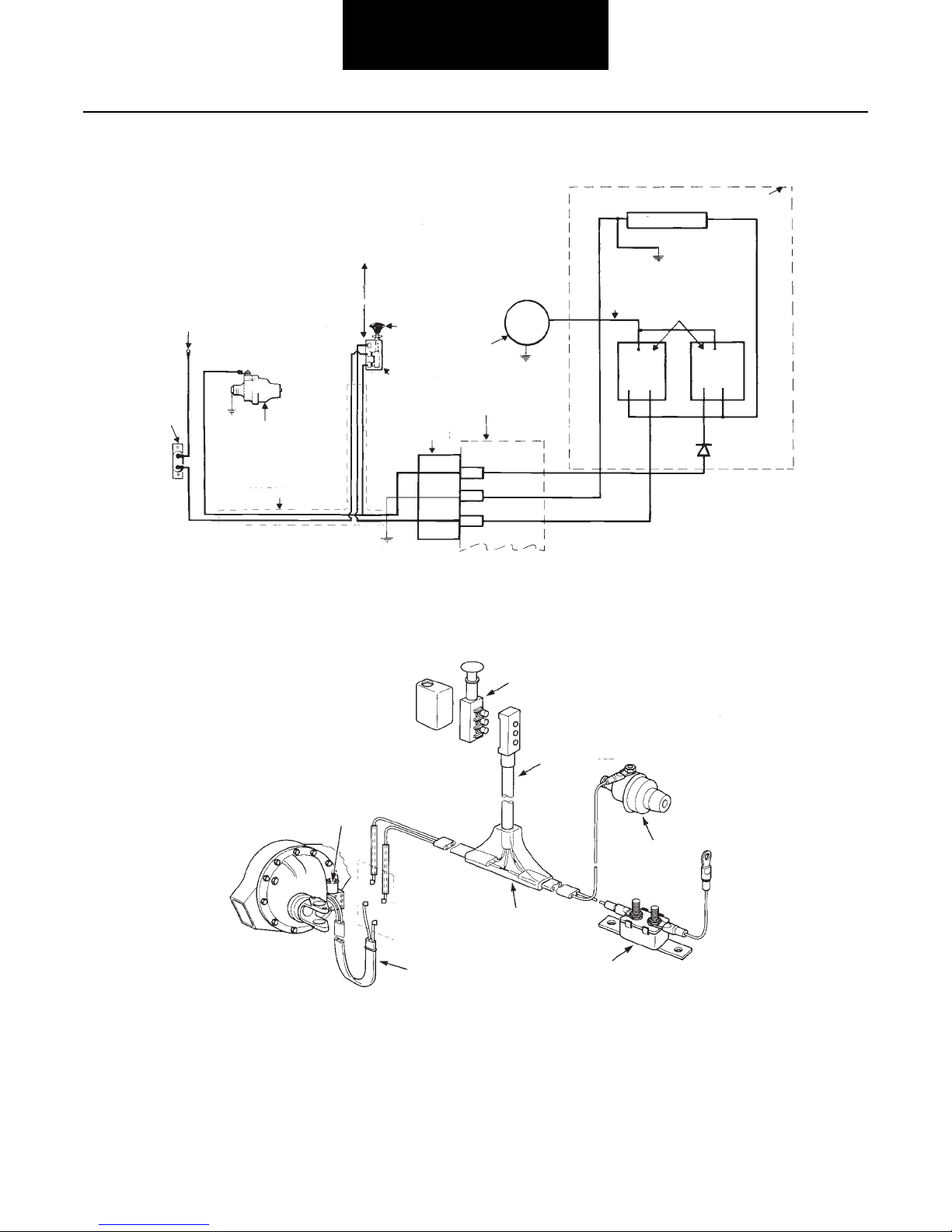
Shift System Electrical Wiring Schematic
Electric Shift System
Circuit Board
Resistor
Up-High
Power Source
(Ignition or
Accessory Switch)
Circuit
Breaker
Speedometer
Adapter
Wiring
Harness
Range
Down-Low
Range
Electrical Shift System Major Components
Switch Knob
Control Switch
Wiring
Harness
Connector
Ground
Motor
Housing
Cover
Ground
Black
Green
Red
Shift Unit Switch
Black
Ground
High
Range
NC NO
Switches
Low
Range
NO NC
Diode
Plug and Cable
Assembly
Electric
Shift Unit
Speedometer
Adapter
Front Wiring
Harness
Rear Wiring
Harness
Circuit Breaker
or Fuse
3

Electric Shift System
Slider Block Inspection Procedure
Bottom of
Base Housing
General Information
• Remove shift unit from axle.
• Move slider block from side to side.
Make sure slider block moves freely
in housing.
4
Electric Shift System
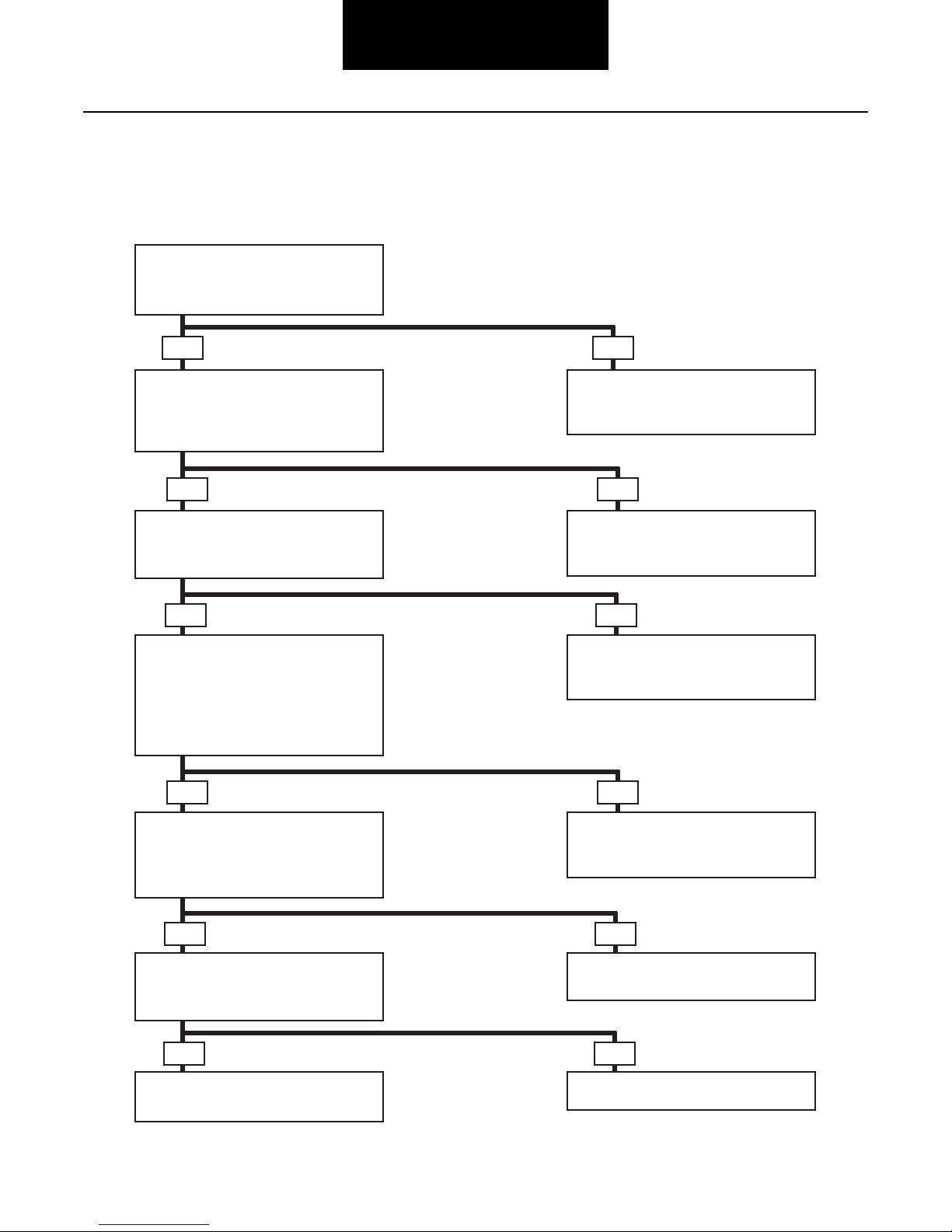
Troubleshooting
Troubleshooting Guide
This chart begins with an improperly operating shift unit. Use with illustrations on pages 3, 4 and 6 to help isolate the problem.
Follow the possible solutions as an aid to system repair.
Axle doesn’t shift ranges.
• Check the circuit breaker.
• Is the circuit breaker closed?
NoYes
Check for power at the shift unit
connector.
• Is there a voltage reading of 9V
or more?
Remove shift unit from axle and
apply voltage.
• Does unit shift properly?
Inspect slider block from bottom
of shift unit. See page 4
• Check to see if slider block is loose
or missing.
• Is slider block in good operating
condition?
Inspect appearance of shift fork
and check fit with depth card.
• Does the fork match the depth
card output? (See page 6)
• Reset circuit breaker or
replace fuse.
• Repeat troubleshooting procedure.
NoYes
• Check the battery, cab switch,
wire harness, and connectors.
• Repeat troubleshooting procedure.
NoYes
• Disassemble and service shift unit.
(See page 8)
• Repeat troubleshooting procedure.
NoYes
• Replace slider block assembly
(See page 8)
• Repeat troubleshooting procedure.
Remove and inspect axle shift parts.
• Are engagement surfaces severely
worn, chipped or broken?
Yes
• Replace worn components.
• Repeat troubleshooting procedure.
5
NoYes
• Rework or replace shift fork.
• Repeat troubleshooting procedure.
No
End of diagnostics
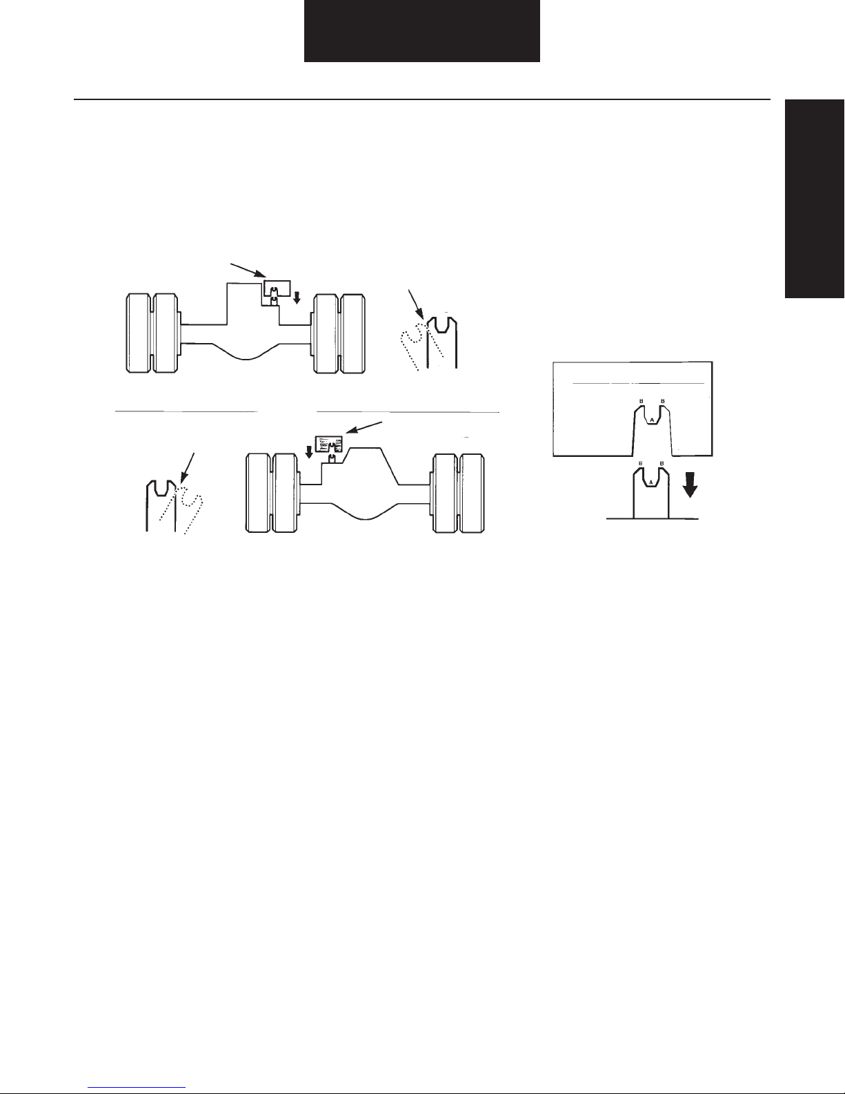
Electric Shift System
Checking Shift Fork Position and Alignment
Electric shift unit failure or shifting problems may be caused
by the shift fork binding on the slider block. Check the shift
fork position and alignment with the Shift Fork Fit-Up card.
Refer to the instructions on the card and the illustration below
to check the shift fork.
Shift Fork Fit-up Card
FORWARD-REAR AXLE
Figure 1
Shift Fork
Range Position
Lo
Hi
Shift Fork
Range Position
Shift Fork
Fit-up Card
If interference at points A and B exists, carefully grind shift
fork until it matches the fit-up card.
Shift Fork Fit-up Card
(Part No. 128039)
Lo
Hi
• Fit-up Card must set flush
on mounting surface of axle
• Shift fork must NOT touch
Fit-up Card at points A and B
2-Speed Shift Fork Fit-Up Card
Procedure:
1. Shift axle to high range so fork is
square to axle face.
2. Remove shift unit and rubber boot.
3. Drop card over shift unit as shown
in (fig. 1) until card touches carrier
surface or interferes with fork.
4. If no interference, fork is OK.
Go to step #6.
5. If card interferes at A or B, care fully grind fork to fit template.
6. Replace boot and reassemble unit.
Printed in U.S.A.
Dana service keeps
you on the road.
For technical assistance call
1-877-777-5360
anywhere in North America
Part no. 128039
10M/1290/MP
Copyright Dana 1991
All right reserved
General Information
REAR-REAR AND SINGLE AXLES
6

Parts Service Kits
Expanded Service Kits
Note: The new
and improved
housing cover
does NOT
require a
gasket
(see page 17).
Electric Shift System
SERVICE KIT NO. DESCRIPTION ITEMS INCLUDED
211319
113745
113746
113759
113753
Circuit Board and Cover Kit
Motor and Lube Kit
Drive Gear and Cam Pin Kit
Slider Block and Lube Kit
Connector and Harness Kit
1-7, 18-19
10, 18-19
5, 9, 12-14, 18
15, 18
20-26
7
 Loading...