

DANA DI-100F User Manual
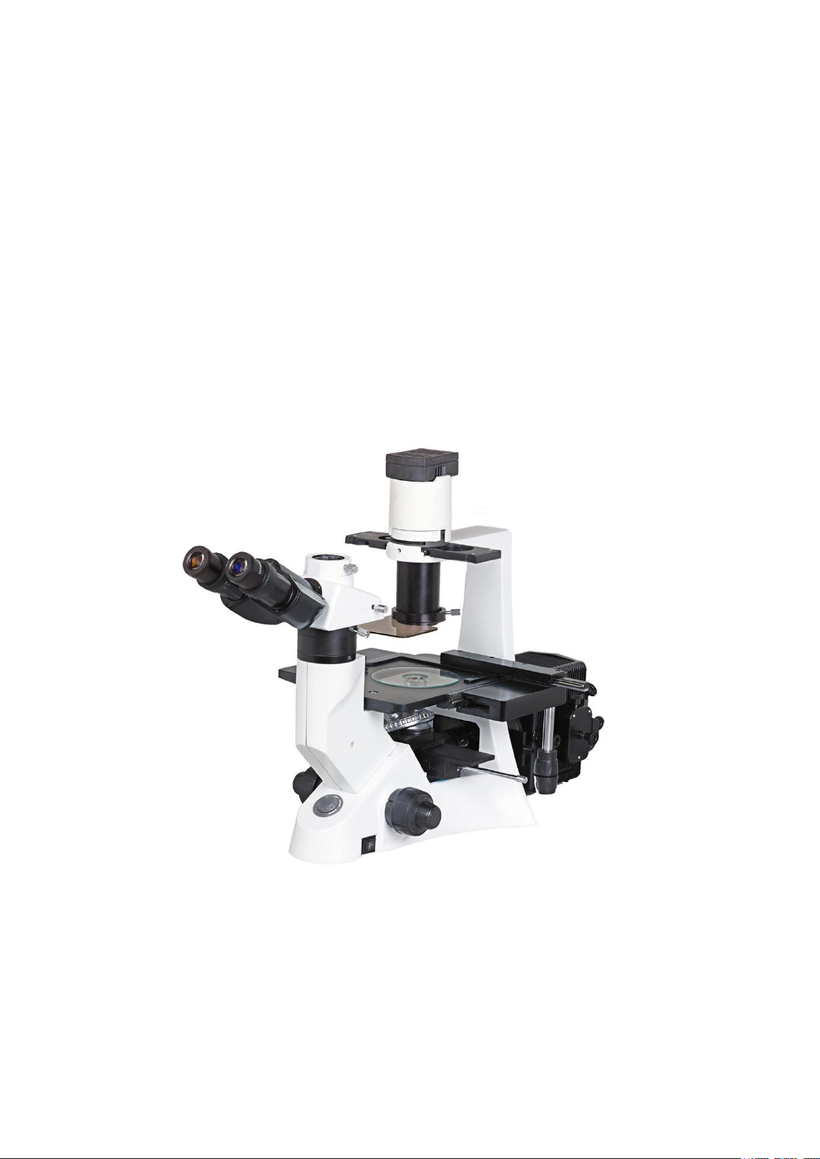
Inversed Fluoresence Microscope
This manual is written for Metallurgical Microscope of DI-100F ..For safety and for
exerting the best performance, making you familiar with the instrument entirely, it is
strongly recommended that you read this manual carefully before using the microscope.
DI-100F
USER MANUAL

1
Content DI-100F
Contents…………………………………………………………………… 1
User Notices………………………………………………………………… 2
1.Components Name……………………………………………………… 4
2.Assembly………………………………………………………………… 5
2.1 Installment figure……………………………………………………… 5
2.2 Installment steps…………………………………………………… 6
3.Adjustment and opertation…………………………………………… 11
3.1 Lamp adjustment for fluorescence observation ………………… 11
3.2 Lamp adjustment for biological observation……………………… 17
4Microscope photography and video…………………………………… 19
4.1Microscope Photography……………………………………………… 19
4.2 Microscope Video…………………………………………………… 20
5.Technical Specifications………………………………………………… 21
5.1 Outfit………………………………………………………………… 21
5.2 Objective Specification…………………………………………… 23
6.Troubleshooting………………………………………………………… 24
2
Notices DI-100F
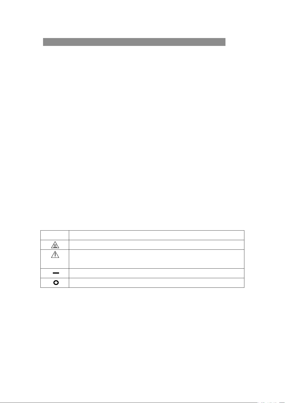
Symbol
Meaning
The surface is very hot, not touch by your hands
Before using ,please read the instruction carefully, improper operation will result in
bodily injure or instruction malfunction.
The main switch on
The main switch off
Safety Note
1. The epi-fluorescent attachment is a precise instrument. Open the box carefully, and avoid
dropping the accessories to ground and causing damage to them.
2. Do keep the instrument out of direct sunlight, high temperature or humidity, dusty and
virations.
3. Make certain that the burner is installed correctly and all cords are connected firmly.
4. Do not open the lamp housing while it is turned on or for at least 10 minutes after it has
been turned off. Lamp housing parts are extremely hot and cause burns if touched.
5. Always be sure to ground (earth) the equipment.
6. Verify that the voltage and the frequency of the AC mains outlet match the setting of the
voltage switch and the frequency switch on the rear of the power supply unit.
7. Always use the power cord provided and make sure that the main switch is moved to
“O”(OFF) before connecting the power cord plug to the wall outlet.
8. To prevent any hazard, always turn the main switch on the power supply unit to “O”
(OFF), unplug the power cord plug from the mains outlet before replacing the burner or
the fuse, and wait for at least 10 minutes before replacing the burner. (Be sure to use a
GCQ-100 mercury burner.)
9. To prevent obstruction of the air flow, it is important to leave enough space around and
above the lamp housing.
Safety Symbol

3
DI-100F
Maintenance and Storage
1. Clean all glass components by wiping gently with gauze. To remove fingerprints or oil
smudges, wipe with gauze slightly moistened with a mixture of ether (70%) and
alcohol (30%).
Since solvents such as ether and alcohol are highly flammable, they must be
handled carefully. Be sure to keep these chemicals away from open flames or potential
sources of electrical sparks-for example, electrical equipment that is being switched on
or off. Also remember to always use these chemicals only in a well-ventilated room.
2. Do not attempt to use organic solvents to clean the non-optical component of the
equipment. To clean these, use a lint-free, soft cloth lightly moistened with a diluted
neutral detergent.
3. Do not disassemble any part of the power supply unit as malfunction or damage may
occur.
4. In order not to impair the safety of the equipment, replace the burner when the counter of
NFP-1 indicates “100.00” hours. To prevent any hazard, always turn the main switch on the
power supply unit to “O” (OFF), unplug the power cord plug from the mains outlet, and
wait for at least 10 minutes before replacing the burner. High-pressure gas is sealed within
the mercury burner. Thus, if it is continued to be used after its service life expectancy, the
glass tube may deform and may sometimes rupture.
4
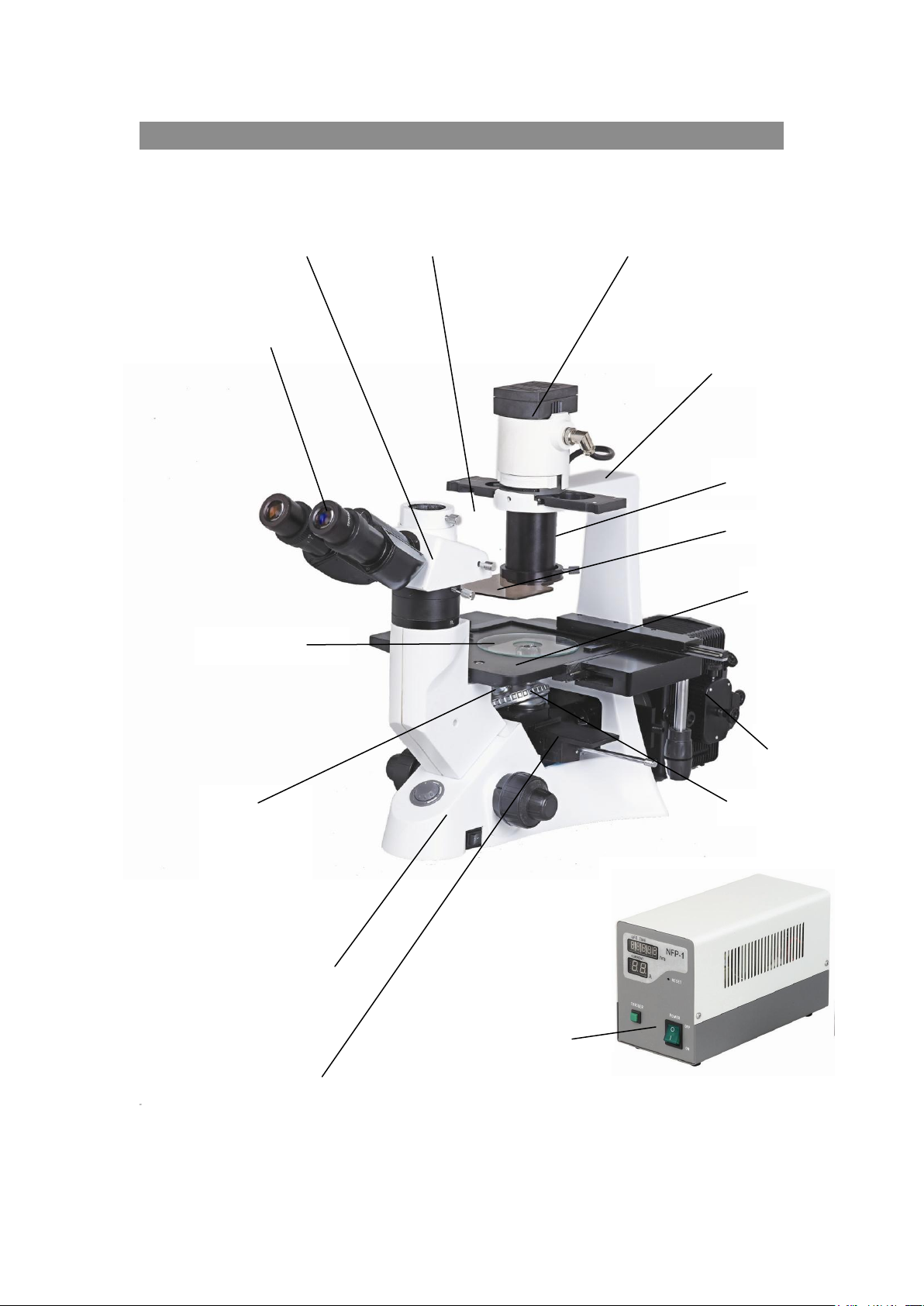
1.Components name DI-100F
Condenser
Illumination bracket
eyepiece
Stage inserted plate
Stage
Body
nosepiece
Objectives
。 4×
。 10×
。 20×
。 40×
NFP-1 Fluorescence power supplier
Protection barrier
B excitation G excitation
l
DI-100F inverted fluorescence microscope
Trinocular tube head Phase contrast slider Lamp
reflected fluorescence units
5
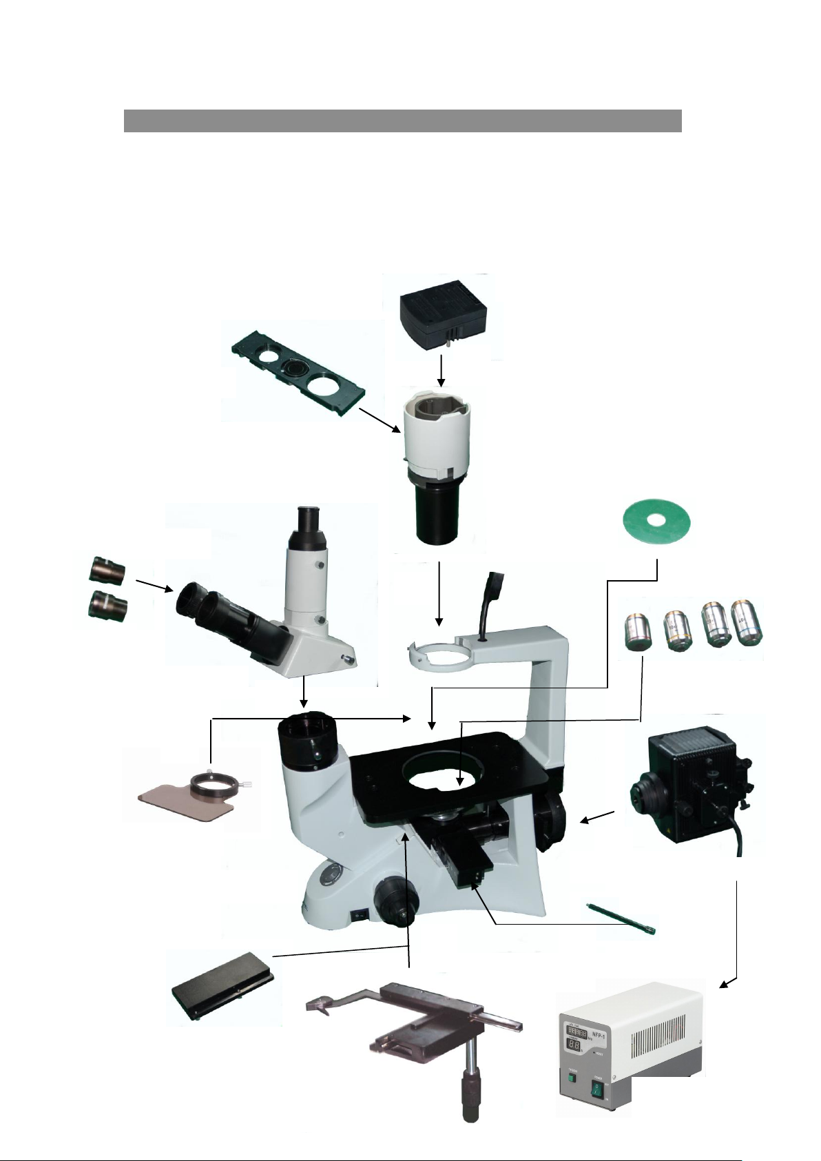
2Installation DI-100
① ② ④
③
⑤ ⑥ ⑦
⑧
Condenser
illumination unit
Phase contrast slider
Lamp house
Eyepiece
Trinocular tube
Objectives
Glass stage
Power supply unit
Mechanical ruler
Body Stand
Stage lengthen splint
⑨
Power supply
⑩
⑾
⑿
Lever
Protection barrier
2.1 Installing diagram
The following figure shows the installation sequence of the components. The number in the
figure shows the installation steps.
Before installing, be sure every components is clean, do not score any parts or glass surface.
Keep well with the supplied hexagon wrench. When changing the components, you will need it again。
6
2.2 Installment steps DI-100F
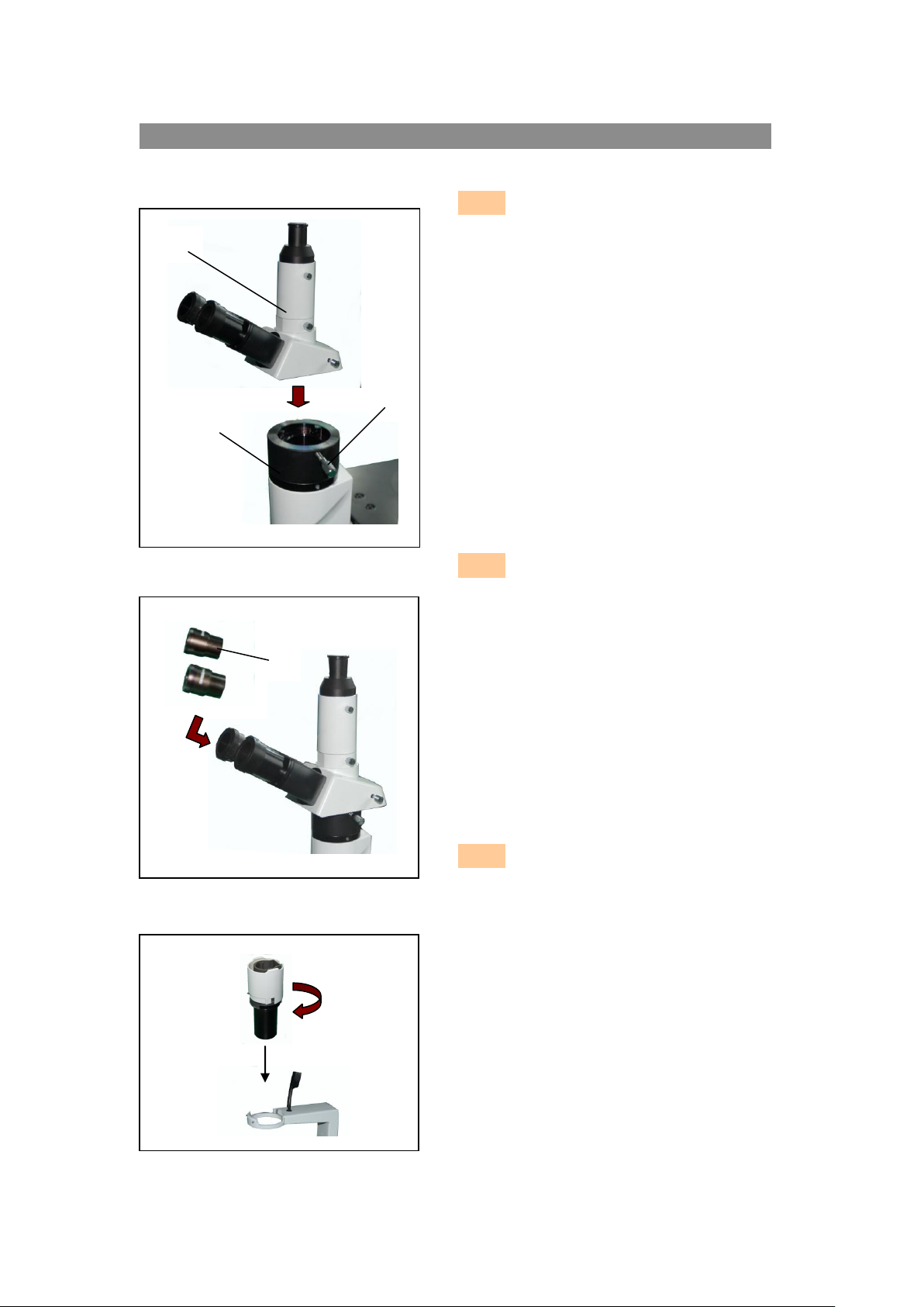
2.2.1 Installing trinocular
head(fig 1)
Loosen the setscrew ② and insert the
trinocular Viewing Head ① into the body
correctly , screw down with bolt③.
2.2.2 Installing eyepiece(fig 2)
Insert the eyepiece④ into tube until they
are against.
2.2.3 Installing condenser
set(fig3)
Install the condenser into the right
direction(fig3)。
图 1
Fig 2
②
①
③
④
Fig 3
7
DI-100F
Fig 4
A
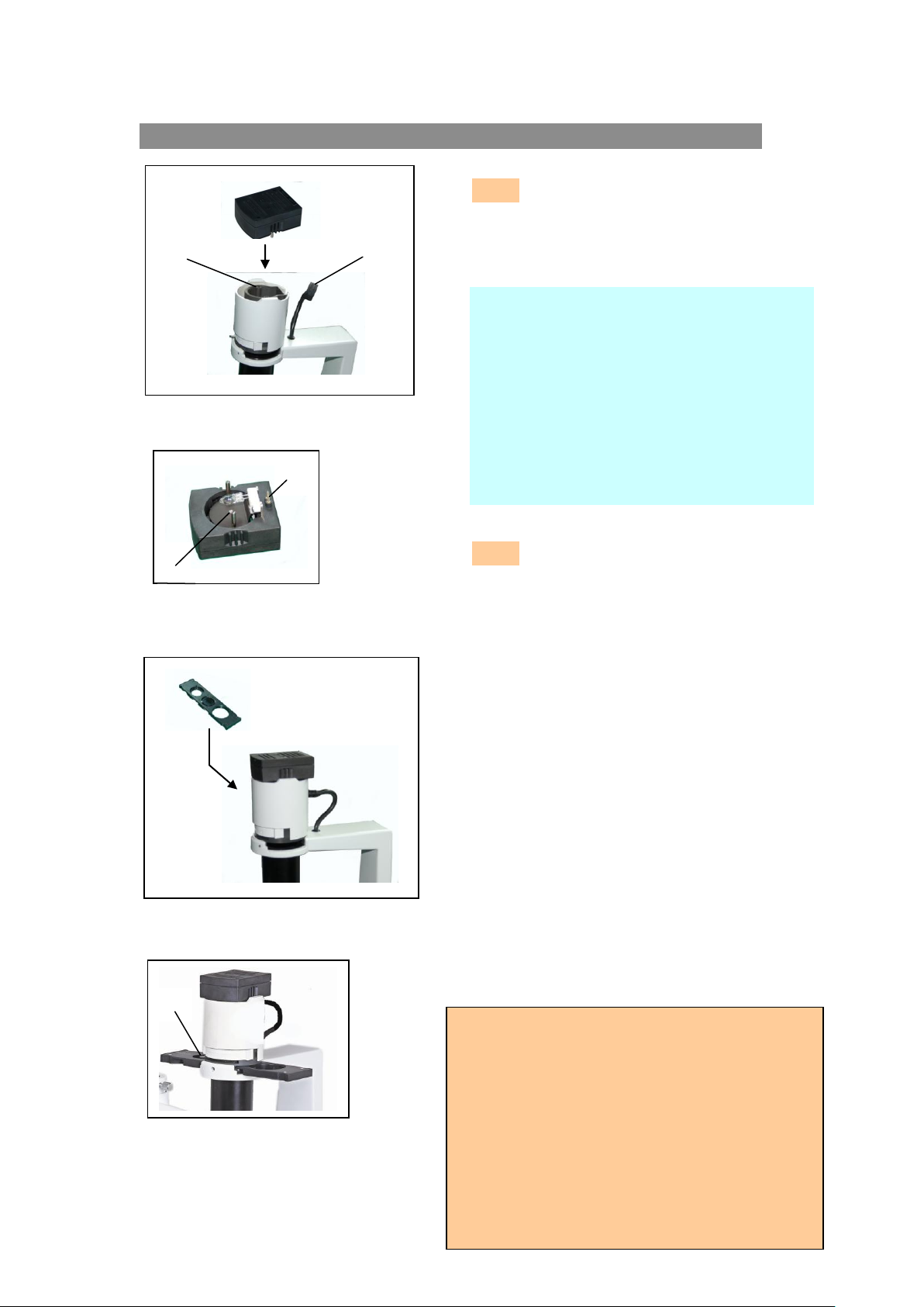
2.2.4 Installing lamp house(fig4、fig5)
Insert the plug A into hole A of power cord. then
insert theplug B into the B hole of the condenser
till there are against. (Fig 6)。
2.2.5 Installing phase contrast
plate(fig6、fig7)
1. Keep the slider① face ( the surface which had
character) up towards,。 Every light ring or opening
has its own located position, so you need to move
them until you heard the “clicked” to ensure the ring
or the opening reache the center of the light
path(show as fig 7)。
2. Turn the aperture diaphragm lever ① to
adjust aperture。Turn the diaphragm to a big
aperture when do phase contrast observation。
● The light ring was centered beforehand, so
it needn’t to adjust in the use process.
If the ring is not in the center, you could
adjust by the centering bolt.
● The 10X/20X light ring is worked with the
10X,20X phase contrast objective, while
the opening is used for bright field .
A
B
A B Fig 5
Fig 6
Notices
Requirement :
1. temprature:0℃~40℃,max humidity:85%。
2. high temperature and moisture will damage
instrument and affect performance。
3. keep the instrument from the dust
environment ,and take the dust cover when no
using 。
4. lay the instrument without vibration place。
Fig 7
①
Replace lamp
1. Turn the swith to off position when using or
need replacement.pull out the lamp house and
then the lamp after it is cool down competely。
2. Insert the new lamp softly to prevent damage。
3. Do not touch the lamp by hands to prevent
reducing lamp expectancy or explode。Clean
the fingerprint by wiping slightly moistened
with ether
8
DI-100F
Fig 8
③
②
①
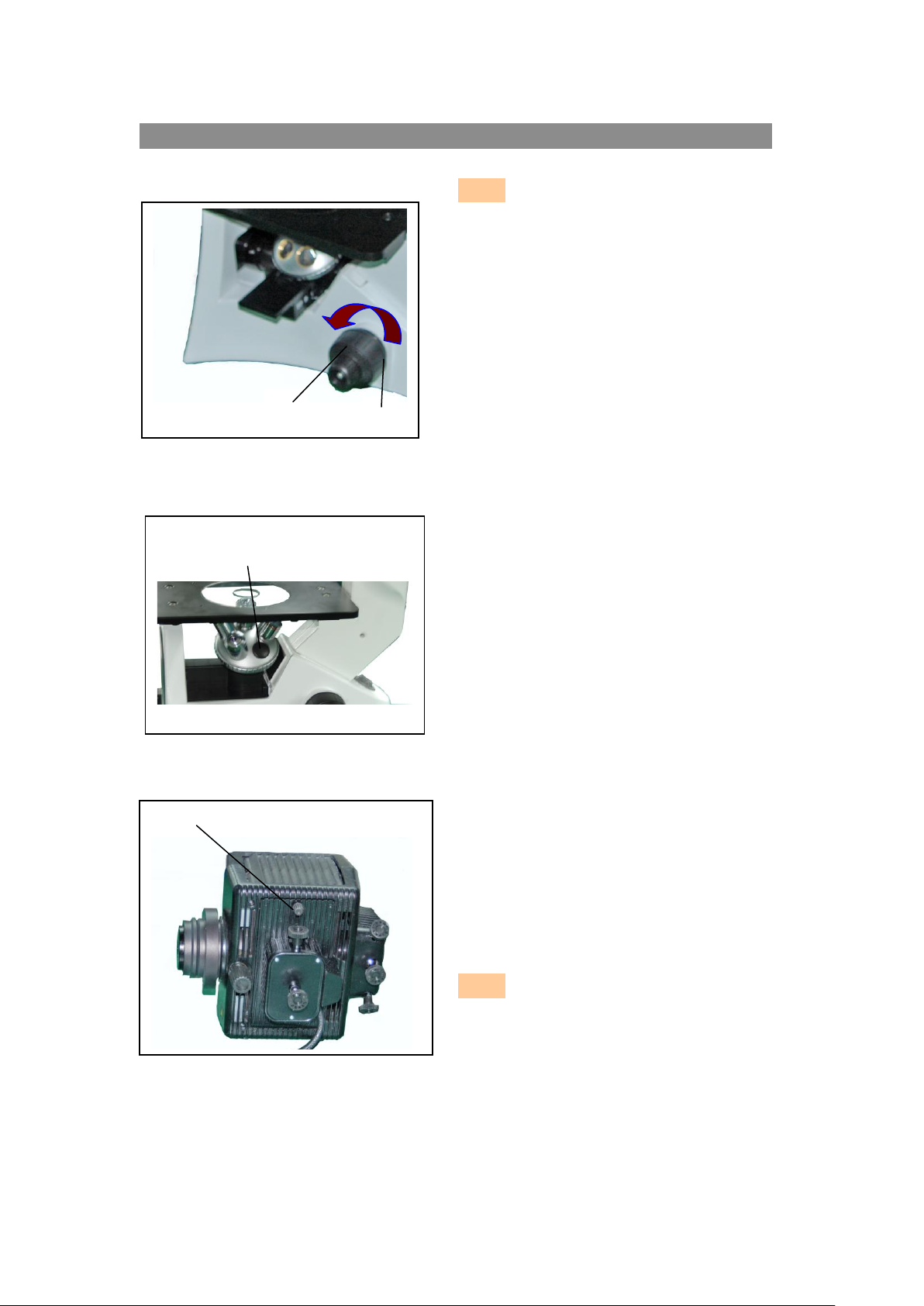
2.2.6 Installing the objective (fig8、fig9)
1. Turning the coarse fusing knob① like the figure
shows till the nosepiece get to its lowest position.
★For ensuring the safety of the instruction
on transportation, the nosepiece is located in the
lowest position and the tension adjustment
collar② is adjusted in a appropriate tight
tension while leaving the factory.
2. Screw the lowest magnification objective on to the
turret from the nearside, then turn the turret
clockwise, mount other objectives according the
magnification sequence of low to high.
◎ Mount objective like this way will make the change
of magnification to be very easy in using.
◎ It also can install the objective through the
stage opening.
★ Clean the objective regularly, the objective used in
the inversed microscope is very sensitivity about
dust.
★ Do cover all the unused holes with turret dust
caps③, to prevent the dust and contamination
entering inside.
★ When operating, use the low magnification objective
(4X or 10X)to search and focus the specimen at
first, then replace the higher magnifications if
necessary.
★ When replace the objective, slowly turning the
nosepiece until you hear “clicked”, that means the
objective enter into the right position—center of
the light path.
2.2.7 Mounting the Mercury Burner (fig10、
fig 11)
1.Loosen the burner socket clamping screw ①, and
remove the burner socket.(fig.1)
2.After removing the foam backstop②, securely insert
the + pole (the wide head) of the specified mercury
burner③ to the lower teminal first and then the –
pole(the thin head) to the upper terminal, then
tighten the two socket clamping screws④.
3.Close the burner socket with burner into the original
position and tighten the socket clamping screw①.
Fig 10
Fig 9
①
 Loading...