

Page 1
Elev82 Touch - Single Desk
PACK B
PACK C
PACK C
EVT-1200 | EVT-1400 | EVT-1600
01-05-2019
ASSEMBLY
INSTRUCTIONS
Elev82 Touch
Single Desk
PACK A
PACK B
Pack A:
1 x DESKTOP
Pack B:
1 x UNDER FRAME
Page 2
FOR ASSEMBLY
PACK A
PACK A & B
PACK C & D
PACK B
PACK C
PACK D
PACK A
PACK A & B
PACK C & D
PACK B
PACK C
PACK D
PACK C & D
PACK C
PACK D
PACK E
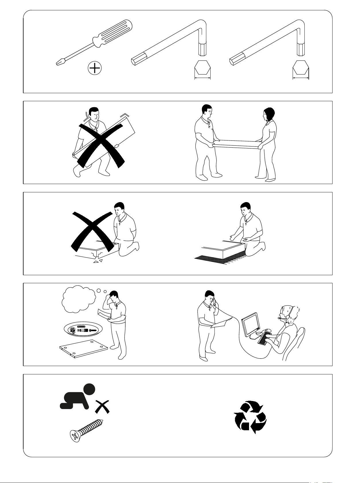
TOOLS REQUIRED
1 x Pozi screwdriver 1 x 4mm Allen key 1 x 5mm Allen key
2 MAN LIFT
DONT STRUGGLE
ALWAYS HANDLE
ITEMS WITH CARE
1,2,3...
IF UNSURE CALL
FOR ASSISTANCE
2
FROM CHILDREN
KEEP FITTINGS AWAY
Page 3
PACK A
PACK B
Please check that you have all the components
PACK B
PACK C
PACK C
PACK A
PACK A
PACK A & B
PACK B
PACK C
PACK A
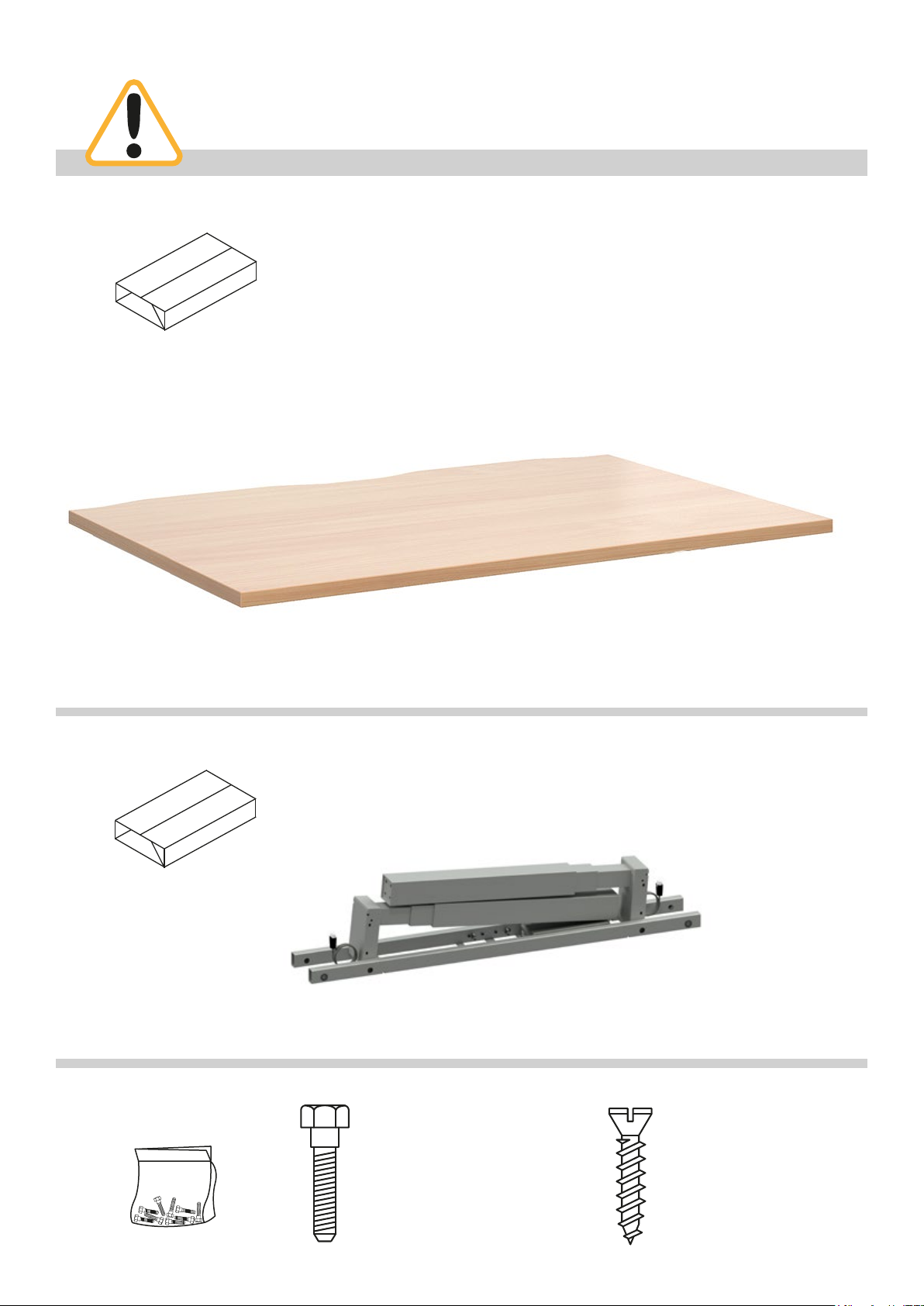
PACK A:
1 x DESKTOP
1200mm = ED128T
1400mm = ED148T
1600mm = ED168T
PACK B
FITTINGS SUPPLIED
PACK B:
1 x UNDER FRAME
Size PCS
M6 x 16mm 8
M10 x 16mm 8
M10 x 20mm 8
Leg pack code = ST-T-*
Size PCS
Ø4 x 25mm 2
Ø5 x 20mm 14
Code to include sufx of colour ordered eg. Silver (S), White (WH) or Black (K)
*
Page 4

ELEV82 TOUCH SINGLE DESK ASSEMBLY
1
Step 1
Unpack your new height
adjustable desk frame and place
on a at surface.
2
Step 2
Unfold both legs into their
upright position.
3
Step 3
Insert the 2 desktop end rails
into the frame cross sections.
Page 5

4
Step 4
Once insterted tighten the bolts
at points A & B.
5
A
B
Step 5
Attach both feet to the leg using
the 8 x bolts provided.
6
Step 6
Once attached, turn the desk
over into its upright position.
2 person lift, do not attempt to
do this without assistance as this
could result in injury or damage
to the product.
Page 6

7
Step 7
Extend the frame to your desired
length (1200
mm). Once extended tighten
1600
all of the grub screws on the
inside face of the cross section.
mm, 1400mm or
8
Step 8
Now that your desk is assembled
you can proceed with the wiring.
Connect both end legs to the
control box, insert the connectors
into ports “M1” & “M2”.
Before proceeding ensure the
connector plugs are connected
properly. You should hear the
plugs click and lock into place.
9
Step 9
You can now attach the desktop
controller. This connector plug
should be inserted into the port
marked “H” on the control box.
Page 7

10
Step 10
The desktop controller can be
positioned on either side of the
desktop. Ensure that once the
controller is connected to the control
box the wires are neatly tucked into
the cable management clips.
Inesrt the wire protector into the
recessed cut out in the top of the
cross section and ensure the wire
passes through the protector.
11
Step 11
You are now ready to connect the
mains lead to the control box. Insert
the gure 8 connector plug into the
corresponding socket on the control
box, this is marked “AC”.
Page 8

12
PACK A
PACK A & B
PACK B
PACK A
PACK A & B
PACK B
Step 12
Now position the desktop onto
the framework ensuring that the
scalloped edge of the desktop is at
the rear of the frame.
Align the holes in the desktop end
rails with the pre-drilled holes on the
underside of the desktop.
Use the wood screws supplied to
attach the top to the frame, if you are
using a cordless/power driver make
sure it is on a low torque setting.
NOTE
Use Ø5 x 20mm wood screws to
attach the top to the frame.
NOTE
If the holes don’t line up,
loosen the grub screws
and adjust the width of the
frame before re-tightening
the grub screws.
13
Step 13
Finally attach the desktop controller
to the underside of the desktop using
the wood screws provided. If you are
using a cordless/power driver make
sure it is on a low torque setting.
There are pre-drilled holes on either
side of the top so the controller can
be attached to the Left or Right of the
desk.
NOTE
Use Ø4 x 25mm wood screws to
attach the controller to the top.
Page 9

14
Step 14
Your desk is now ready to be connected to the mains outlet.
Before you proceed with operating your new desk it is recommended that you perform a full
reset of the controller to calibrate the height of each leg.
This can be done using the following steps;
• Press both buttons at the same time for 3 seconds.
• Continue pressing the buttons until both columns are in lowest position.
• Keep pressing the buttons until control box makes 1 beep.
• When control box makes 1 beep, it is conrmed that reset has been completed and buttons
can be released.
• Now the desk is operational.
• If the desk is disconnected by accidently pulling out the plugs at the control box, motors,
handset, main power source or system status reach overload, overheat etc. then the desk
must be reset.
• If the desk is powered off intentionally at the main power switch, then the desk does not
need to be reset.
Operating the desk
Press this button, to operate the desk for upwards running.
Press this button, to operate the desk for downwards running.
Page 10

15
Step 15
Upgrading to the Digital control unit
Make sure that your height adjustable desk is turned off and unplugged from the mains.
Unplug the controller supplied with your height adjustable desk and replace with the digital
control unit. Fix this to your top using the wood screws provided.
After connecting the digital control unit you will need to perform a reset.
Reset
• Press both up & down buttons at the same time for 3 seconds. Continue pressing the buttons
until both columns are in lowest position. When the reset is nished, the control box makes a
beep and the buttons can be released.
• When conducting reset, the display shows “000” in last 100mm stroke. When the reset hsd
nished, the display shows starting height again.
• If releasing up & down buttons before the display shows ”000”, the desk goes back to normal
operation.
• Reset is necessary for rst operation of the desk.
Normal operation
• Press any button. 3-digits display shows current desk height in centimeters.
• Press up or down button to adjust the desk height.
• When no button has been pressed for 10 seconds, display goes off. Press any button to light
up the display again.
• When no button has been pressed for 30 seconds, the system goes to <0.1 W standby mode.
Long press any button to wake the system up. Display shows desk height again.
Memory position
The digital control unit supports 4 memory positions. to set the positions follow these steps;
1. Operate the desk to preferred height.
2. Press any of 1,2,3,4 buttons together with up or down buttons for 2 seconds to store the
current height. Display shows P1/P2/P3/P4 when the position has been stored.
3. Now, hold any of the 1,2,3 or 4 buttons until the desk reaches the stored height.
Stored postion can only be overwritten, not to be cleared.
 Loading...