

Dalsa S3-24-01k40-00-R, S3-24-02k40-00-R, S3-14-01k40-00-R, S3-14-02k40-00-R, S3-24-04k40-00-R User Manual

Spyder3
10 June 2013
03-032-20117-01
www.teledynedalsa.com
Monochrome Camera User’s Manual
S3-14-01k40-00-R
S3-14-02k40-00-R
S3-24-01k40-00-R
S3-24-02k40-00-R
S3-24-04k40-00-R

2 Spyder3 S3-14 and S3-24 Monochrome Camera User's Manual
North America
605 McMurray Rd
Waterloo, ON N2V 2E9
Canada
Tel: 519 886 6000
Fax: 519 886 8023
www.teledynedalsa.com
sales.americas@teledynedalsa.com
support@teledynedalsa.com
Europe
Teled yne DALSA GmbH
Felix-Wankel-Strasse 1
D-82152 Krailling (Munich)
Germany
Tel: +49 - 89 - 89545730
Fax: +49 - 89 – 895457346
www.teledynedalsa.com
sales.europe@teledynedalsa.com
support@teledynedalsa.com
Asia Pacific
Ikebukuro East 13F
3-4-3 Higashi-Ikebukuro
Toshima-ku, Tokyo 170-0013
Japan
Tel: 81 3 5960 6353
Fax: 81 3 5960 6354 (fax)
www.teledynedalsa.com
sales.asia@teled yned alsa.com
support@teledynedalsa.com
© 2013 Teled yne DALSA. All information provided in this manual is believed to be accurate and reliable. No responsibility is
assumed by Teledyne DALSA for its use. Teledyne DALSA reserves the right to make changes to this information without notice.
Reproduction of this manual in whole or in part, by any means, is prohibited without prior permission having been obtained from
Teled yne DALSA.
About Teledyne Technologies and Teledyne DALSA, Inc.
Teled yne Technologies is a leading provider of sophisticated electronic subsystem s, instrumentation and communication products,
en gin eered syst em s, aerosp ace engin es, and en er gy and pow er generatio n system s. Teled y ne Tech n ologies’ op erat ion s ar e p rim ari ly
located in the United States, the United Kingdom and Mexico. For more in for m ation, visit Teled y ne Tech n ologies’ w ebsite a t
www.teledyne.com.
Teled yne DALSA, a Teledyne Technologies company, is an international lead er in high performance digital imaging and
semiconductors with approximately 1,000 employees worldwide, headquartered in Waterloo, Ontario, Canada. Established in 1980,
the company designs, develops, manufactures and markets digital imaging products and solutions, in addition to providing MEMS
prod u cts and serv ices. For more in form a tion, visit Teled yne DALSA’s websit e at www.teled ynedalsa.com.
Support
For furt her inform ation not in clu d ed in t his m a nual, or for information on Teledyn e D ALSA’s extensive lin e o f im age sen sin g
products, please contact:
Industry Standards
Teled yne DALSA and this model of the Spyder3 camera support th e Cam era Lin k™ com m u nication s int er face for vision
applications. Camera Link is a high speed communications interface for vision applications. It provides a standard method of
communication between digital cameras and frame grabbers.
Detailed information on Camera Link is available in the Teled yne DALSA Camera Link Implementation Road Map documentation,
available from the Know ledge Center on our Web site: (http:/ / www.teledynedalsa.com/ mv/ knowledge/ appnotes.aspx).
03-032-20117-01 Teledyne DALSA

Spyder3 S3-14 and S3-24 Monochrome Camera User's Manual 3
Contents
SYSTEM PRECAUTIONS AND CLEANING .................................................................................................................................. 5
THE SPYDER3 S3-14 AND S3-24 CAMERAS ............................................................................................................................. 7
CAMERA HIGHLIGHTS ..............................................................................................................................................................................................................7
CAMERA PERFORMANCE SPECIFICATIONS ....................................................................................................................................................................................8
CERTIFICATIONS ....................................................................................................................................................................................................................10
RESPONSIVITY ......................................................................................................................................................................................................................10
DERATING CURVES ................................................................................................................................................................................................................12
MECHANICALS ......................................................................................................................................................................................................................14
IMAGE SENSOR .....................................................................................................................................................................................................................16
SOFTWARE AND HARDWARE SETUP .........................................................................................................................................................................................17
SETUP STEPS: OVERVIEW .......................................................................................................................................................................................................17
STEP 1. INSTALL AND CONFIGURE THE FRAME GRABBER AND GRAPHICS CARD .................................................................................................................................18
STEP 2. CONNECT POWER AND CAMERA LINK CABLES.................................................................................................................................................................18
INPUT SIGNALS, CAMERA LINK................................................................................................................................................................................................22
CAMERA LINK VIDEO TIMING ..................................................................................................................................................................................................23
STEP 3. ESTABLISH COMMUNICATION WITH THE CAMERA ............................................................................................................................................................26
USING CAMERA LINK WITH SPYDER3 CAMERAS .........................................................................................................................................................................27
CAMERA OPERATION ............................................................................................................................................................ 29
FACTORY SETTINGS ...............................................................................................................................................................................................................29
RETURNING CAMERA SETTINGS ...............................................................................................................................................................................................29
SAVING AND RESTORING SETTINGS .........................................................................................................................................................................................32
CAMERA OUTPUT FORMAT ......................................................................................................................................................................................................33
EXPOSURE MODE, LINE RATE AND EXPOSURE TIME ....................................................................................................................................................................39
EXPOSURE MODES IN DETAIL ..................................................................................................................................................................................................40
SENSOR OUTPUT FORMAT ......................................................................................................................................................................................................44
DATA PROCESSING ................................................................................................................................................................................................................47
ANALOG AND DIGITAL SIGNAL PROCESSING CHAIN ....................................................................................................................................................................48
RETURNING CALIBRATION RESULTS AND ERRORS ......................................................................................................................................................................59
END-OF-LINE SEQUENCE ........................................................................................................................................................................................................60
SETTING THRESHOLDS ...........................................................................................................................................................................................................61
LOOK-UP TABLES .................................................................................................................................................................................................................62
SAVING AND RESTORING PRNU AND FPN COEFFICIENTS ...........................................................................................................................................................63
DIAGNOSTICS .......................................................................................................................................................................................................................65
RETURNING VIDEO INFORMATION............................................................................................................................................................................................67
RETURNING AVERAGED LINES OF VIDEO ...................................................................................................................................................................................68
TEMPERATURE MEASUREMENT ................................................................................................................................................................................................68
VOLTAGE MEASUREMENT .......................................................................................................................................................................................................69
CAMERA FREQUENCY MEASUREMENT .......................................................................................................................................................................................69
ASCII COMMANDS: REFERENCE ..............................................................................................................................................................................................70
ERROR HANDLING ................................................................................................................................................................................................................75
APPENDIX A .......................................................................................................................................................................... 77
CLEARING DARK CURRENT .....................................................................................................................................................................................................77
APPENDIX B .......................................................................................................................................................................... 85
CAMERA LINK REFERENCE, TIMING, AND CONFIGURATION TABLE .................................................................................................................................................85
CAMERA LINK BIT DEFINITIONS...............................................................................................................................................................................................86
Teledyne DALSA 03-032-20117-01

4 Spyder3 S3-14 and S3-24 Monochrome Camera User's Manual
CAMERA LINK CONFIGURATION TABLES ....................................................................................................................................................................................87
APPENDIX C .......................................................................................................................................................................... 91
EMC DECLARATION OF CONFORMITY .......................................................................................................................................................................................91
REVISION HISTORY ............................................................................................................................................................... 92
INDEX.................................................................................................................................................................................... 93
03-032-20117-01 Teledyne DALSA

Spyder3 S3-14 and S3-24 Monochrome Camera User's Manual 5
System Precautions and
Cleaning
Precautions
Read these precautions and this manual carefully before using the camera.
Confirm th at th e camera’s p ackaging is u nd am aged before op ening it. If th e p ackaging is d amaged please
contact the related logistics personnel.
Do not open the housing of the camera. The warranty is voided if the housing is opened.
Keep the camera housing temperature in a range of 0 °C to 65 °C during operation.
Do not operate the camera in the vicinity of strong electromagnetic fields. In addition, avoid electrostatic
charging, violent vibration, and excess moisture.
To clean the device, avoid electrostatic charging by using a dry, clean absorbent cotton cloth dampened
with a small quantity of pure alcohol. Do not use methylated alcohol. To clean the surface of the camera
housing, use a soft, dry cloth. To remove severe stains use a soft cloth dampened with a small quantity of
neutral detergent and then wipe dry. Do not use volatile solvents such as benzene and thinners, as they
can d amage the surface finish. Further cleaning instructions are below.
This camera does not support hot plugging. Power down and disconnect power to the camera before you
add or replace system components.
Electrostatic Discharge and the CMOS Sensor
Image sensors and the camera bodies housing are susceptible to damage from electrostatic discharge
(ESD). Electrostatic charge introduced to the sensor window surface can induce charge buildup on the
underside of the window that cannot be readily dissipated by the dry nitrogen gas in the sen sor package
cavity. The charge normally dissipates within 24 hours and the sensor returns to normal operation.
Protecting Against Dust, Oil, and Scratches
The sensor window is part of the optical path and should be handled like other optical components, with
extreme care. Dust can obscure pixels, producing dark patches on the sensor response. Dust is most
visible when the illumination is collimated. The dark patches shift position as the angle of illumination
changes. Dust is normally not visible when the sensor is positioned at the exit port of an integrating
sphere, where the illumination is diffuse. Dust can normally be removed by blowing the wind ow surface
using an ionized air gun. Oil is usually introduced during handling. Touching the surface of the window
barehanded will leave oily residues. Using rubber fingercots and rubber gloves can prevent
contamination. However, the friction between rubber and the window may prod uce electrostatic charge
that may damage the sensor. To avoid ESD damage and to avoid introducing oily residues, avoid
touching the sensor. Scratches diffract incident illumination. When exposed to uniform illumination, a
Teledyne DALSA 03-032-20117-01

6 Spyder3 S3-14 and S3-24 Monochrome Camera User's Manual
sensor with a scratched window will normally have brighter pixels adjacent to darker pixels. The location
of these pixels will change with the angle of illumination.
Cleaning the Sensor Window
Recommended Equipment
Glass cleaning station with microscope within clean room.
3M ionized air gun 980 (http:/ / solutions.3mcanada.ca/ wps/ portal/ 3M/ en_CA/ WW2/ Country/ )
Ionized air flood system, foot operated.
Swab (HUBY-340CA-003) (http:/ / www.cleancross.net/ modules/ xfsection/ article.php?articleid=24)
Single drop bottle (FD-2-ESD)
E2 (Eclipse optic cleaning system (www.photosol.com)
Procedure
Use localized ionized air flow on to the glass during sensor cleaning.
Blow off mobile contamination using an ionized air gun.
Place the sensor under the microscope at a magnification of 5x to determine the location of any
remaining contamination.
Clean the contamination on the sensor using one drop of E2 on a swab.
Wipe the swab from left to right (or right to left but only in one direction). Do this in an overlapping
pattern, turning the swab after the first wipe and with each subsequent wipe. Avoid swiping back
and forth with the same swab in order to ensure that particles are removed and not simply
transferred to a new location on the sensor window. This procedure requires you to use multiple
swabs.
Discard the swab after both sides of the swab have been used once.
Repeat until there is no visible contamination present
03-032-20117-01 Teledyne DALSA

Spyder3 S3-14 and S3-24 Monochrome Camera User's Manual 7
The Spyder3 S3-14 and S3-24
Cameras
Camera Highlights
The Spyder3 CL surpasses its predecessor, the Spyder2, with 3x more responsivity and 2x the speed. At
its core is dual line scan technology that achieves unprecedented responsivity and throughput rates of 80
megapixels per second, without impacting noise.
The Spyder3 CL features the Camera Link™ serial interface and is fully programmable, offering precise
control over key performance variables such as gain and offset and improved ease of use and setup.
The temperature range performance of the SC-14 and SC-24 models has increased from an operating
temperature of 0 °C to 50 °C to an operating temperature of 0 °C to 65 °C.
Features and Programmability
Broadband responsivity up to 408 ±16 DN(nJ/ cm2) @10 dB gain, 8 bit
1024, 2048, or 4096 pixels, 14 µm x 14 µm (1k and 2k) and 10 µm x 10 µm (4k) pixel pitch, 100% fill
factor
Up to 68 kHz line rates
Dynamic range up to 1400:1
Data transmission exceeding 10 meters
±50 µm x, y sensor alignment
Base Camera Link configuration (8 or 12 bit data on 1 or 2 taps depending on camera model)
Serial interface (ASCII, 9600 baud, adjustable to 19200, 57600, 115200), through Camera Link.
Mirroring and forward/ reverse control.
Programmable gain, offset, exposure time and line rate, trigger mode, test pattern output, and
camera diagnostics.
Tall pixel, high sensitivity, or low sensitivity mode available.
Flat-field correction—minimizes lens vignetting, non-uniform lighting, and sensor FPN and PRNU.
Applications
FPD inspection
Pick and place
Container inspection
Wood / tile / steel inspection
100% print inspection (lottery tickets, stamps, bank notes, paychecks)
Postal sorting
Glass bottle inspection
Industrial metrology
Food inspection
Web inspection
Models
Teledyne DALSA 03-032-20117-01

8 Spyder3 S3-14 and S3-24 Monochrome Camera User's Manual
Model Number
Description
S3-24-01K40-00-R
1k resolution, 2 sensor taps. Base Camera Link configuration.
S3-24-02K40-00-R
2k resolution, 2 sensor taps. Base Camera Link configuration.
S3-14-01K40-00-R
1k resolution, 1 sensor tap. Base Camera Link configuration.
S3-14-02K40-00-R
2k resolution, 1 sensor tap. Base Camera Link configuration.
S3-24-04k40-00-R
4k resolution, 2 sensor taps. Base Camera Link configuration.
Feature / Specification
1k
2k
4k
Imager Format
dual line scan
Resolution
1024 pixels
2048 pixels
4096 pixels
Pixel Fill Factor
100 %
Pixel Size
14 µm x 14 µm
10 µm x 10 µm
Sensitivity Mode
High, low , or tall pixel
Antiblooming
100 x
Gain Range
± 10 dB
Speed
1k
2k
4k
Data Rate
40 mp / s and 80 mp / s
80 mp / s
Maximum Line
Rate
2 tap model
68 kHz (80 MHz)
36 kHz (80 MHz)
18.5 kHz
1 tap model
36 kHz (40 MHz)
18.5 kHz (40 MHz)
NA
Optical Interface
1k and 2k
4k
Lens Mount
M42 x 1, C and F*
M58 x 0.75, F*
Focal Length
6.56 mm ± 0.25
Sensor Alignment
x ± 50 µm
y ± 50 µm
z ± 0.25 mm
z ± 0.2 º
Mechanical Interface
1k and 2k
4k
Camera Size
72 mm (h) x 60 mm (l) x 60 mm (w)
60 mm (h) x 72 mm (l) x 60 mm (w)
Mass
< 300 g
Connectors
6 pin male Hirose power
MDR26 female data connector
Electrical Interface
1k and 2k
4k
Input Voltage
+ 12 to +15 Volts DC
Power Dissipation
< 5 W (1k and 2k)
< 7 W (4k)
The Spyder3 CL camera is available in these models.
Table 1: Spyder3 CL Camera Models Overview
Camera Performance Specifications
Table 2: Camera Performance Specifications
03-032-20117-01 Teledyne DALSA

Spyder3 S3-14 and S3-24 Monochrome Camera User's Manual 9
Operating Temperature
0 ºC to 65 ºC
Bit Wid th
8 or 12 bits user selectable
Output Data Configuration
Base Camera Link
Specifications
Unit
-10dB
0dB
+10dB
Min
Typ
Max
Min
Typ
Max
Min
Typ
Max
Broadband
responsivity
DN /
(nJ/cm²)
1k and 2k Dual line
652.8
2064
6528
1k and 2k Single line
326.4
992
3264
4k Dual line
431
1363
4310
4k Single line
216
682
2155
Random noise rms
DN 3
6.5 9.2
20.5 30
65
Dynamic range
DN : DN
1k and 2k Dual line
500:1
1400:1
203:1
324:1
59:1
108:1
1k and 2k Single line
500:1
1400:1
203:1
324:1
59:1
108:1
4k Dual and Single
1225:1
387:1
122.3:1
FPN global
DN p-p
Uncorrected
52.8
169.6
536
Corrected
32
32
64
PRNU ECD
Uncorrected local
%
8.5
8.5
11.5
Uncorrected global
%
10
10
10
Corrected local
DN p-p
80
80
95
Corrected global
DN p-p
80
80
95
PRNU ECE
Uncorrected local
%
8.5
12
37
Uncorrected global
%
10
12
37
Corrected local
DN p-p
80
237
752
Corrected global
DN p-p
80
208
752
SEE (calculated)
nJ / cm²
Dual line
6.35
1.92
0.61
Single line
12.2
4.0
1.2 NEE (calculated)
pJ / cm²
Dual line
4.6
4.5
4.6
Single line
9.2
9.3
9.2
Saturation output
amplitude
DN
3968
±80
DC offset
DN
96
160
336
*Lens mount adapters are available. Contact Teledyne DALSA Sales for more information.
Table 3: Camera Operating Specifications
Teledyne DALSA 03-032-20117-01

10 Spyder3 S3-14 and S3-24 Monochrome Camera User's Manual
Compliance
The CE Mark, FCC Part 15, and Industry Canada ICES-003 Evaluation of the DALSA Spyder3 CL S3-14and S3-24
cameras meet the following requirements:
CISPR 22, EN 55022 and EN 61326 Class A Emissions Requirements, EN 55024, and EN 61326 Immunity to
Disturbances
Spectral Responsivity. Nominal Gain
0
250
500
750
1000
1250
1500
1750
2000
2250
2500
400 500 600 700 800 900 1000 1100
Wavelength (nm)
Responsivity {DN/(nJ/cm²)}
High Sensitivity Mode
Low Sensitivity Mode
Test conditions unless otherwise noted
12-bit values, Flat Field Correction (FFC) enabled.
CCD Pixel Rate: 40 megapixels/ second per sensor tap.
Line Rate: 5000 Hz.
Nominal Gain setting unless otherwise specified.
Light Source: Broadband Quartz Halogen, 3250k, with 750 nm high pass filter installed.
Ambient test temperature 25 °C.
Unless specified, all values are referenced at 12 bit.
Exposure mode disabled.
Unless specified, dual line mode.
Notes
1. PRNU measured at 50% SAT.
Certifications
Table 4: EMC Compliance Standards
Responsivity
03-032-20117-01 Teledyne DALSA

Spyder3 S3-14 and S3-24 Monochrome Camera User's Manual 11
Spectral Responsivity. Nominal Gain
0
10
20
30
40
50
60
70
80
90
100
400 500 600 700 800 900 1000 1100
Wavelength (nm)
Responsivity {DN/(uJ/cm²)}
High Sensitivity Responsivity
Low Sensitivity Responsivity
Figure 1: Spyder3 CL 1k and 2k Responsivity
Figure 2: Spyder3 CL 4k Responsivity
Teledyne DALSA 03-032-20117-01

12 Spyder3 S3-14 and S3-24 Monochrome Camera User's Manual
Derating Curves
Figure 3: 1k and 2k Derating Curves
03-032-20117-01 Teledyne DALSA

Spyder3 S3-14 and S3-24 Monochrome Camera User's Manual 13
4K model: Change in DC Offset vs Temperature
(12bit,Integration Time 200us)
0.000
20.000
40.000
60.000
80.000
100.000
120.000
140.000
160.000
180.000
200.000
0C 10C 20C 30C 40C 50C 60C
Temperature (Celsius)
DN
+10dB HSM
+10dB LSM
-10dB LSM
4K model: Change in Noise vs. Temperature
(12bit,0dB Gain, Integration time 100us)
7.400
7.600
7.800
8.000
8.200
8.400
8.600
8.800
9.000
9.200
9.400
0C 10C 20C 30C 40C 50C 60C
Temperature (Celcius)
DN(rms)
HSM
LSM
4K model: Change in FPN vs. Temperature
(12bit,0dB Gain, Integration Time 100us )
0.000
5.000
10.000
15.000
20.000
25.000
30.000
0C 10C 20C 30C 40C 50C 60C
Temperature
DN
HSM
LSM
4K model:Change in PRNU vs. Temperature
(12bit, 0dB, Integration Time 100us)
0.000
10.000
20.000
30.000
40.000
50.000
60.000
70.000
80.000
0C 10C 20C 30C 40C 50C 60C
Temperature
DN
LSM
HSM
Changes in DC offset with Integration Time
(12bit,0dB, HSM, 4K model)
0
20
40
60
80
100
120
140
3.3 2.0 1.0 0.5 0.3 0.2 0.1 0.1
Integration Time (ms)
DN
Figure 4: 4k Derating Curves
Teledyne DALSA 03-032-20117-01

14 Spyder3 S3-14 and S3-24 Monochrome Camera User's Manual
2
3
4
UNLESS OTHERWISE SPECIFIED
1. UNITS: MM
2. DRAWING PER
ASME Y14.5M-1994
3. TOLERANCES:
LINEAR ±0.15
ANGLES ±0.5
`
SURFACE FINISH
AUTHOR
APPROVED BY
APPLICATION/PROJECT
PROPRIETARY
3.2
APPROVALS
REV
5
7
B
0
.
2
46 B0.2
6
B
0
.
2
38 B0.2
6.56 B0.25
IMAGE AREA
[OPTICAL DISTANCE]
M42x1 Z 4.5
30 B0.05
CENTER OF
IMAGE AREA
36 B0.05
CENTER OF
IMAGE AREA
M4x0.7 Z 6
MAX TORQUE 25 IN-LB
(56)
(60)
7
2
B
0
.
2
60 B0.2
6 B0.2
(30)
(
3
4
)
M4x0.7 Z 6
(BOTH SIDES)
MAX TORQUE 25 IN-LB
M4x0.7 Z 6
(BOTH SIDES)
MAX TORQUE 25 IN-LB
3
8
B
0
.
2
00
INITIAL RELEASE OCT 22/2010
(12)
(
1
9
)
Ivan Bruulsema
Mechanicals
Figure 5: 1k and 2k Mechanical Dimensions
03-032-20117-01 Teledyne DALSA

36 B0.05
CENTER OF
IMAGE AREA
30 B0.05
CENTER OF
IMAGE AREA
6
0
B
0
.
2
72 B0.2
57 B0.2
4
6
B
0
.
2
3
8
B
0
.
2
6 B0.2
38 B0.2
6
B
0
.
2
(19)
(34)
(
3
0
)
(
4
8
)
(
5
6
)
(
6
0
)
6.56 B0.25
IMAGE AREA
[OPTICAL DISTANCE]
M4x0.7 Z 6
(BOTH SIDES)
MAX TORQUE 25 IN-LB
M58x0.75 Z 4.5
M4x0.7 Z 6
MAX TORQUE 25 IN-LB
M4x0.7 Z 6
(BOTH SIDES)
MAX TORQUE 25 IN-LB
Spyder3 S3-14 and S3-24 Monochrome Camera User's Manual 15
Figure 6: 4k Mechanical Dimensions
Teledyne DALSA 03-032-20117-01

16 Spyder3 S3-14 and S3-24 Monochrome Camera User's Manual
Tap 2Tap 1
CCD Readout Shift Register
CCD Readout Shift Register
N
Pixels
N
Pixels
N
=1024, 2048, 4096
Pixel 1, 1
Tap 1
CCD Readout Shift Register
CCD Readout Shift Register
N
Pixels (14µm x 14µm)
N
Pixels (14µm x 14µm)
N
=1024, 2048
Pixel 1, 1
Mounting
Heat generated by the camera must be allowed to move away from the camera. Mount the camera on the
front plate (using the provided mounting holes) with maximum contact to the area for best heat
dissipation.
Figure 7: Spyder3 Mounting Example
Image Sensor
The camera uses Teledyne DALSA’s d u al line scan sensor. The camera can be configured to read out in
either high or low sensitivity mode, tall pixel mode, and either forward or reverse shift direction.
Figure 8: 2 Tap Sensor Block Diagram
Figure 9: 1 Tap Sensor Block Diagram (1k and 2k only)
03-032-20117-01 Teledyne DALSA

Spyder3 S3-14 and S3-24 Monochrome Camera User's Manual 17
Software and Hardware Setup
Host System Requirements
To achieve best system performance, the following minimum requirements are recommended:
Base Camera Link frame grabber.
Operating system: Windows XP Professional, Windows Vista, Windows 7 (either 32-bit or 64-bit for
all) are supported.
Setup Steps: Overview
Take the following steps in order to setup and run your camera system. They are described briefly below
and in more detail in the following sections.
1. Install and Configure Frame Grabber
If your host computer does not have a Base Camera Link frame grabber, or equivalent, then you need to
install one.
2. Connect Power, and Camera Link I/O Cables
Connect a power cable from the camera to a +12 VDC to +15 VDC power supply.
If using the external signals connect the external control cable to the camera.
3. Establish communicating with the camera
The quickest and easiest way to communicate with the camera is through the u se of a terminal program
(e.g., Microsoft HyperTerminal is a widely available application).
4. Check camera LED, settings and test pattern
Ensure that the camera is operating properly by checking the LED, the current settings, and by acquiring
a test pattern.
5. Operate the Camera
At this point you will be ready to operate the camera in order to acquire and retrieve images, set camera
functions, and save settings.
Teledyne DALSA 03-032-20117-01

18 Spyder3 S3-14 and S3-24 Monochrome Camera User's Manual
!
Step 1. Install and configure the frame grabber
and graphics card
Install Frame Grabber
Install a Base Camera Lin k fr am e gr a bber accor d ing to the m anufacturer ’s d escr ip tion .
A list of frame grabbers recommended by Teledyne DALSA and supporting the Spyder3 cameras is
available on the Teledyne DALSA Web site here:
www.teledynedalsa.com/ mv/ products/ framegrabbers.aspx
Install Graphics Card
Determine the graphics card that supports your selected frame grabber and follow th e m an u fact u rer’s
installation instructions.
Step 2. Connect Power and Camera Link Cables
WARNING! Grounding Instructions
Static electricity can damage electronic components. Please discharge any static electrical
charge by touching a grounded surface, such as the metal computer chassis, before performing
any hardware installation.
The use of cable types and lengths other than those specified may result in increased emission or
decreased immunity and performance of the camera.
03-032-20117-01 Teledyne DALSA
Spyder3 S3-14 and S3-24 Monochrome Camera User's Manual 19
!
Hirose 6-pin Circular Male
5
4
6
2
3
1
Mating Part: HIROSE
HR10A-7P-6S
Table 5: Hirose Pin Description
Pin
Description
Pin
Description
1
Min +12 to Max +15 VDC
4
GND
2
Min +12 to Max +15 VDC
5
GND
3
Min +12 to Max +15 VDC
6
GND
!
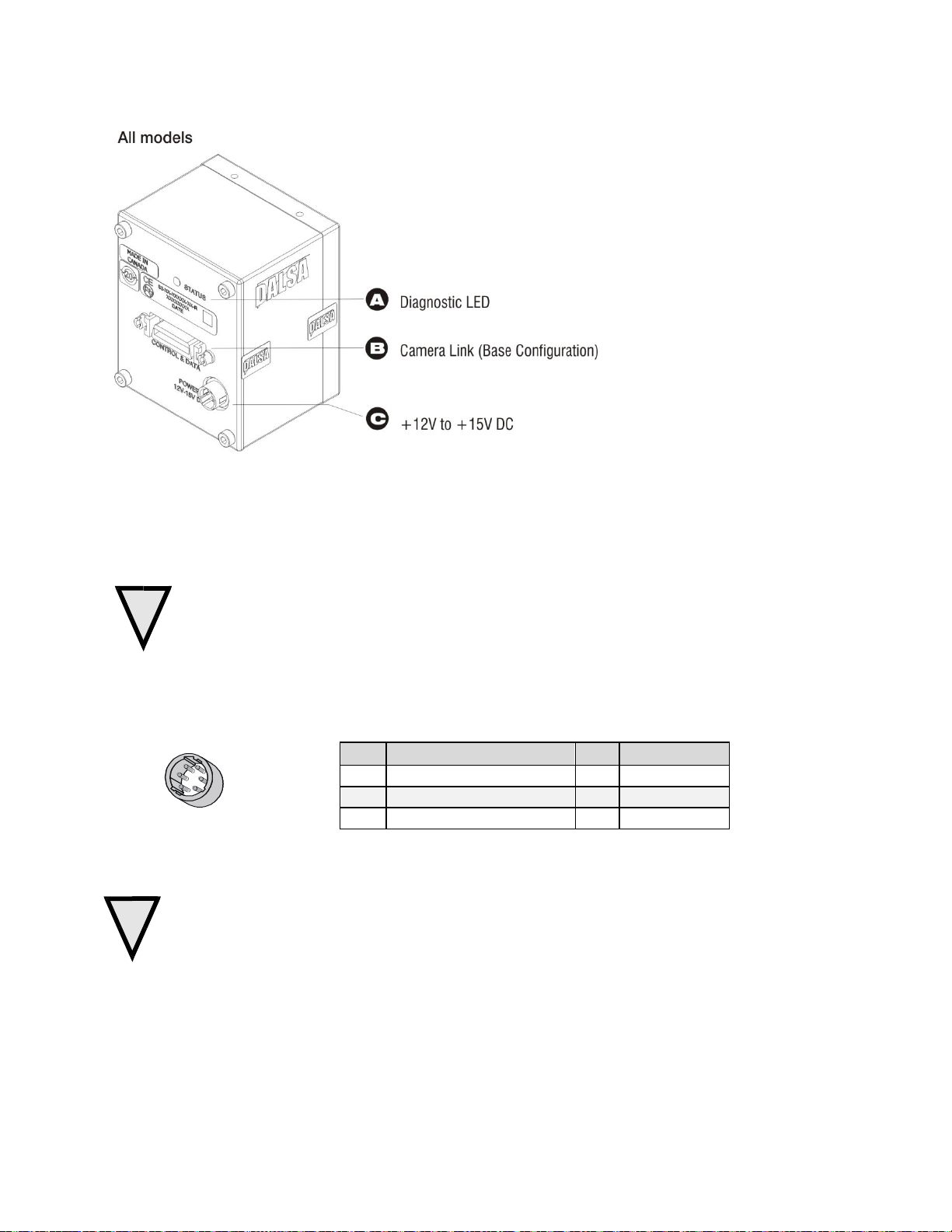
Figure 10: Hirose 6-pin Circular Male—Power Connector
Power Connector
WARNING: It is extremely important that you apply the appropriate voltages to your camera.
Incorrect voltages may damage the camera. Input voltage requirement: +12 V to +15 V DC.
The camera requires a single 6-pin Hirose connector with a single voltage input +12 VDC to
+15 VDC for power. The camera meets all performance specifications using standard switching power
supplies, although well-regulated linear supplies provide optimum performance.
WARNING: When setting up the camera’s power supplies follow these guidelines:
Apply the appropriate voltages.
Protect the camera with a 2 amp slow -blow fuse between the power supply and the camera.
Do not use the shield on a multi-conductor cable for ground.
Keep leads as short as possible in order to reduce voltage drop.
Use high-quality linear supplies in order to minimize noise.
Note: If your power supply does not meet these requirements, then the camera performance specifications are not
guaranteed.
Teledyne DALSA 03-032-20117-01

20 Spyder3 S3-14 and S3-24 Monochrome Camera User's Manual
Priority
Color of Status LED
Meaning
1
Flashing Red
Fatal Error. For example, camera temperature is too high and camera
thermal shutdown has occurred.
2
Solid Red
Loss of functionality.
3
Flashing Green
Camera initialization or executing a long command (e.g., flat field
correction commands ccp or ccf).
4
Solid Green
Camera is operational and functioning correctly.
Parameter
Description
Notes
gsl
The camera returns one of the following values:
1 = red (loss of functionality)
2 = green (camera is operating correctly)
5 = flashing green (camera is performing a function)
6 = flashing red (fatal error)
Status LED
The camera is equipped with a red / green LED used to display the status of the camera's operation. The
table below summarizes the operating states of the camera and the corresponding LED states.
When more than one condition is active, the LED indicates the cond ition with the highest priority. Error
and warning states are accompanied by corresponding messages that further describe the current camera
status.
Table 6: Diagnostic LED
Returning the LED Status
Use the gsl command to retu rn th e status of the cam era’s LED.
Camera Link Command
03-032-20117-01 Teledyne DALSA

Spyder3 S3-14 and S3-24 Monochrome Camera User's Manual 21
Configuration
8 Bit Ports Supported
Serializer Bit
Width
Number of
Chips
Number of
MDR26
Connectors
Applicable
Camera
Models
Base
A, B, C
28 1 1
The various
models
Base Configuration
One Channel Link Chip + Camera Control + Serial Communication
Camera Connector
Right Angle
Frame
Grabber
Channel Link Signal
1 1 inner shield
14
14
inner shield
2
25
X0-
15
12
X0+ 3 24
X1-
16
11
X1+ 4 23
X2-
17
10
X2+
5
22
Xclk-
18 9 Xclk+
6
21
X3-
19 8 X3+ 7 20
SerTC+
20 7 SerTC-
8
19
SerTFG-
21 6 SerTFG+
9
18
CC1-
22 5 CC1+
10
17
CC2+
23 4 CC2-
11
16
CC3-
**3M part 14X26-SZLB-XXX-0LC is a complete
cable assembly, including connectors.
Unused pairs should be terminated in 100
ohms at both ends of the cable.
Camera Link Data Connector
Figure 11: Camera Link MDR26 Connector
The Camera Link interface is implemented as Base Configuration in the Spyder3 cameras. Refer to section
Setting the Camera Link Mode for details on setting the Camera Link configuration.
Table 7: Camera Link Hardware Configuration Summary
Table 8: Camera Link Connector Pin out
Teledyne DALSA 03-032-20117-01

22 Spyder3 S3-14 and S3-24 Monochrome Camera User's Manual
24 3 CC3+
12
15
CC4+
25 2 CC4-
13
13
inner shield
26
26
inner shield
Signal
Configuration
CC1
EXSYNC
CC2
PRIN
CC3
Direction
CC4
Spare
i
Notes:
*Exterior Overshield is connected to the shells of the connectors on both ends.
**3M part 14X26-SZLB-XXX-0LC is a complete cable assembly, including connectors.
Unused pairs should be terminated in 100 ohms at both ends of the cable.
Inner shield is connected to signal ground inside camera
Table 9: Teledyne DALSA Camera Control Configuration
See Appendix B for the complete Teledyne DALSA Camera Link configuration table, and refer to the
Knowledge Center on Teledyne DALSA’s Web site, for the official Camera Link documents.
Input Signals, Camera Link
The camera accepts control inputs through the Camera Link MDR26F connector.
The camera ships in internal sync, internal programmed integration (exposure mode 7) TDI Mode.
EXSYNC (Triggers Frame Readout)
Frame rate can be set internally using the serial interface. The external control signal EXSYNC is optional
and enabled through the serial interface. This camera uses the falling edge of EXSYNC to trigger pixel
readout.
Direction Control
Control the CCD shift direction through the serial interface. Use the software command scd to determine
whether the direction control is set via software control or via the Camera Link control signal on CC3.
03-032-20117-01 Teledyne DALSA

Spyder3 S3-14 and S3-24 Monochrome Camera User's Manual 23
Clocking Signal
Indicates
LVAL (high)
Outputting valid line
DVAL (high)
Valid data (unused, tied high)
STROBE (rising edge)
Valid data
FVAL (high)
Outputting valid frame (unused, tied high)
Output Signals, Camera Link
These signals indicate when data is valid, allowing you to clock the d ata from the camera to your
acquisition system. These signals are part of the Camera Link configuration and you should refer to the
Teledyne DALSA Camera Link Implementation Road Map for the standard location of these signals,
available from the Knowledge Center on our Web site:
(http:/ / www.teledynedalsa.com/ mv/ knowledge/ appnotes.aspx).
The cam era internally d igit izes 12 bits and ou tp uts the 8 M SB or all 12 bits d ep end ing on the cam era’s
Camera Link operating mode.
Camera Link Video Timing
Figure 12: Spyder3 Overview Timing Showing Input and Output Relationships
Teledyne DALSA 03-032-20117-01

24 Spyder3 S3-14 and S3-24 Monochrome Camera User's Manual
Figure 13: Spyder3 Fixed (Programmed) Integration Timing with External EXSYNC
03-032-20117-01 Teledyne DALSA

Spyder3 S3-14 and S3-24 Monochrome Camera User's Manual 25
Symbol
Definition
Min (ns)
twSYNC
The minimum low width of the EXSYNC pulse when not in SMART
EXSYNC mode.
100
twSYNC
(SMART)
*
The minimum low width of the EXSYNC pulse when in SMART EXSYNC
modes to guarantee the photosites are reset.
3,000
twSYNC_INT
The minimum width of the high pu lse w hen th e ―SMART EXSYNC‖
feature is turned off
100
twSYNC_INT
(SMART)
*
Is the in tegration tim e w h en th e ―SMART EXSYNC‖ fea ture is av ailable
and turned on. Note that the minimum time is necessary to guarantee
proper operation.
3,000
tLINE PERIOD
(t LP)
The minimum and maximum line times made up of tTransfer, tREADOUT
plus tOVERHEAD to meet specifications.
14,700 (1k 2 tap)
27,778 (1k 1 tap)
27,778 (2k 2 tap)
54,054 (2k 1 tap)
55,775 (4k 2 tap)
tTransfer
The time from the reception of the falling edge of EXSYNC to the rising
edge of LVAL when pretrigger is set to zero. Pretrigger reduces the
num ber of clocks to t h e risin g ed g e o f LVAL bu t d oesn’t chan g e th e t im e to
the first valid pixel. If the fixed integration time mod e of operation is
available and selected then the integration time is added to the specified
value.
3,725 ±25 (1k
and 2k)
4,100±25 (4k)
twFixed Int.
Fixed Integration Time mode of operation for variable exsync frequency.
800
tREADOUT
Is the number of pixels per tap times the read out clock period.
25,600 (1k 1 tap))
12,800 (1k 2 tap)
51,200 (2k 1 tap)
25,600 (2k 2 tap)
51,200 (4k 2 tap)
tOVERHEAD
Is the number of pixels that must elapse after the falling edge of LVAL
before the EXSYNC signal can be asserted. This time is used to clamp the
internal analog electronics
425±25
(All models)
thPR
Applies when the PRIN exposure control feature is enabled. The PRIN
signal must be held a minimum time after the EXSYNC falling edge to
avoid losing the integrated charge
To Be
Determined
twPR_LOW
Minimum Low time to assure complete photosite reset
3,000
tPR_SET
The nominal time that the photo sites are integrating. Clock
synchronization will lead to integration time jitter, which is shown in the
specification as +/ - values. The user should command times greater than
these to ensure proper charge transfer from the photosites. Failure to meet
this requirement may result in blooming in the Horizontal Shift Register.
3,000
Table 10: Spyder3 Input and Output
Teledyne DALSA 03-032-20117-01

26 Spyder3 S3-14 and S3-24 Monochrome Camera User's Manual
Step 3. Establish Communication with the
Camera
Power on the camera
Turn on th e cam era’s p ow er su p p ly. You m ay have to w ait u p to 60 seco n d s w hile th e cam era w arms u p
and prepares itself for operation.
Connect to the camera
In order for you to communicate with the camera, a serial connection in the Camera Link cable needs to
be established. The frame grabber manufacturers should be able to provide a solution in order to
communicate through this serial link. Terminal software can also be provided by the frame grabber
manufacturer. Stand ard terminal software, such as Microsoft HyperTerminal, can be used if the COM
port is allocated by the frame grabber. Start your GUI and establish communication with the camera.
Check LED Status
If the camera is operating correctly at this point, the diagnostic LED will flash for 10 seconds and then
turn solid green.
Software Interface
All the camera features can be controlled through the ASCII interface.
03-032-20117-01 Teledyne DALSA

Spyder3 S3-14 and S3-24 Monochrome Camera User's Manual 27
Using Camera Link with Spyder3 Cameras
All of the camera features can be controlled through the serial interface. The camera can also be used
without the serial interface after it has been set up correctly. For example, functions available include:
Controlling basic camera functions such as gain and sync signal source.
Flat field correction.
Mirroring and readout control
Generating a test pattern for debugging.
The serial interface uses a simple ASCII-based protocol and the PC does not require any custom software.
Note: This command set may be different from those used by other Teledyne DALSA cameras. You
should not assume that these commands perform the saI me as those for older cameras.
Complete Command List
A list of all the available commands is included in ASCII Commands: Reference, page 70.
Serial Protocol Defaults
8 data bits
1 stop bit
No parity
No flow control
9.6kbps
Camera does not echo characters
Command Format
The camera responds to a simple ASCII-based protocol. When entering commands, remember that:
A carriage return <CR> ends each command.
A space or multiple space characters separate parameters. Tabs or commas are invalid parameter
separators.
Upper and lowercase characters are accepted
The backspace key is supported
The cam era w ill an sw er each com m and w ith either <CR><LF> ―OK >" or <CR>< LF>"Error xx: Error
Messag e >" or ― Warning xx: Warn ing Message >‖ . Th e ">" is u sed exclu sively as t h e last ch aracter
sent by the camera.
The following parameter conventions are used in the manual:
• i = integer value
• f = real number
• m = member of a set
• s = string
• t = tap id
• x = pixel column number
• y = pixel row number
Example: to return the current camera settings
gcp <CR>
Teledyne DALSA 03-032-20117-01

28 Spyder3 S3-14 and S3-24 Monochrome Camera User's Manual
Camera Help Screen
For quick help, the camera can return all available commands and parameters through the serial
interface.
There are two different help screens available. One lists all of the available commands to configure
camera operation. The other help screen lists all of the commands available for retrieving camera
param eter s (th ese are called ―get‖ com m and s).
To view the help screen listing all of the camera configur ation commands, use the command h.
To view a help screen listing all of the ―get‖ com mand s, u se the co m mand gh.
The camera configuration command help screen lists all commands available. Parameter ranges
displayed are the extreme ranges available. Depending on the current camera operating conditions, you
may not be able to obtain these values. If this occurs, values are clipped and the camera returns a warning
message.
Some commands may not be available in your current operating mode. The help screen displays NA in
this case.
03-032-20117-01 Teledyne DALSA

Spyder3 S3-14 and S3-24 Monochrome Camera User's Manual 29
At this point you are ready to start operating the camera in order to acquire images, set camera functions,
and save settings.
Camera Operation
Factory Settings
When the camera is powered up for the first time, it operates using the following factory settings:
High sensitivity mode
Forward CCD shift direction
No binning
Exposure mode 7 (Programmable line rate & max exposure time)
5000 Hz line rate
Readout mode: Off
Mirroring mode: 0, left to right
Factory calibrated analog gain and offset
8 bit output
sag enabled (1k and 2k use). (It is recommended that you use the ssg command with the 4k in
order to maintain valid LUT calibration.)
LUTs enabled (4k default), factory calibrated @ -10 dB.
Returning Camera Settings
The camera parameter screen (obtained using the gcp command) returns all of the camer a’s curren t
settings. The table below lists all of the gcp screen settings.
Teledyne DALSA 03-032-20117-01

30 Spyder3 S3-14 and S3-24 Monochrome Camera User's Manual
gcp
GCP Screen
Description
GENERAL CAMERA SETTINGS
Camera Model No.:
S3-x0-0xK40-00-R
Camera model number.
Camera Serial No.:
xxxxxxxxx
Camera serial number.
Firmware Version:
xx-xx-xxxxx-xx
Firmware design revision number.
CCI Version:
xxxxx.xx
CCI version number.
FPGA Version:
xxx.xx
FPGA revision number.
UART Baud Rate:
9600
Serial communication connection speed set
with the sbr command.
Dual Scan Mode:
High Sensitivity
Current sensitivity mode set with the smm
command. See section Sensitivity Mode for
details.
Camera Link Mode:
2 taps, 8 bits
Current bit depth setting set with the clm
command.
Mirroring Mode
0, left to right
Tap readout direction: left to right, or right to
left. Set with the smm command.
Readout Mode
Off
Current readout mode status. Set using the
srm command.
Cable Parameter
200
The cable parameter. Set using the scb
command.
Exposure Mode:
2
Current exposure mode value set with the sem
command. See the Setting the Camera Link
Mode section for details.
SYNC Frequency:
5000 Hz
Current line rate. Value is set with the ssf
command. See the Setting the Camera Link
Mode section for details.
Exposure Time:
200 µSec
Current exposure time setting. Value is set
with the set command. See the Setting the
Camera Link Mode section for details.
CCD Direction:
internal/forward
Current direction setting set with scd
command. Refer to section
CCD Shift Direction for d etails.
Horizontal Binning:
1
Current horizontal binning factor set w ith the
sbh command.
Video Mode:
video
Current video mode value set with the svm
command. See section Generating a Test
Pattern for details.
Region of Interest:
(1,1) to (1024, 1)
Region of interest size set with the roi
command. See section Setting a Region of
Interest (ROI) for details.
End-Of-Line
Sequence:
on
States whether an end of line sequence is
turned on or off. Set using the els command.
See section End -of-line Sequence for details.
FFC Coefficient Set:
0
Current pixel coefficient set loaded. Refer to
section Saving and Restoring PRNU and FPN
Coefficients for details.
To read all current camera settings, use the command:
03-032-20117-01 Teledyne DALSA

Spyder3 S3-14 and S3-24 Monochrome Camera User's Manual 31
FPN Coefficients:
off
States whether FPN coefficients are on or off.
Set with the epc command. Refer to section
Analog and Digital Signal Processing Chain
for details.
PRNU Coefficients:
off
States whether PRNU coefficients are on or off.
Set with the epc command. Refer to section
Analog and Digital Signal Processing Chain
for details.
Number of Line
Samples:
1024
Number of lines samples set with the css
command. See section Returning Vid eo
Information for details.
Upper Threshold
3600
Upper threshold value set with the sut
command.
See section End -of-line Sequence for details.
Lower Threshold
400
Lower threshold value set w ith the slt
command. See section End -of-line Sequence
for details.
Analog Gain (dB):
0.0 0.0
Analog gain settings set with the sag
command. See section Analog and Digital
Signal Processing Chain for details.
Analog Gain
Reference(dB):
0.0 0.0
Analog reference gain set with the ugr
command.
See section Analog and Digital Signal
Processing Chain for details.
Total Analog Gain
(dB):
5.5 5.5
This is the sum of the analog gain and analog
gain reference values and is the total analog
gain being used by the camera.
Analog Offset:
70 70
Analog offset settings set with the sao
command. See section Analog and Digital
Signal Processing Chain for details.
Digital Offset:
0 0
Digital offset settings set with the sdo
command. See section Analog and Digital
Signal Processing Chain for details.
Background Subtract:
0 0
Background subtract settings set with the ssb
command. See section Analog and Digital
Signal Processing Chain for details.
System Gain (DN):
4096 4096
Digital gain settings set with the ssg
command. See section Analog and Digital
Signal Processing Chain for details.
Teledyne DALSA 03-032-20117-01

32 Spyder3 S3-14 and S3-24 Monochrome Camera User's Manual
Parameter
Description
lpc i
Loads your previously saved pixel coefficients from non-volatile memory to active status. 0:
factory calibration. 1 – 4: user sets.
rfs
Restores the cam era’s factor y settin gs. The FPN and PRNU coefficients are reset to 0.
rus
Restores the camera's last saved user settings and FPN and PRNU coefficients.
wfc i
Write all current FPN coefficients to non-volatile memory. 1 – 4 available sets.
wil i
Wr ite cu r r en t LUT’s to no n -volatile memory. 1- 4 available sets.
wpc i
Write all current PRNU coefficients to non-volatile memory. 1 – 4 available sets.
wus
Write all of the user settings to non -volatile memory.
4 sets of user
pixel coefficients
User
Settings
Current
Session
wus wpc,wfc,
rus lpc,
Factory
Settings
1 set of factory
pixel coefficients
For each camera operating mode:
Low Sensitivity
High Sensitivity Forward
High Sensitivity Reverse
Tall Pixel
Saving and Restoring Settings
Use these commands to select, load, and save factory, user, and coefficient sets.
Camera Link Commands
For each camera operating mode (high sensitivity forward direction, high sensitivity reverse direction,
low sensitivity, or tall pixel), the camera has distinct factory settings, current settings, and user settings. In
addition, there is one set of factory pre-calibrated pixel coefficients and up to four sets of user created
pixel coefficients for each operating mode.
Figure 14: Saving and Restoring Overview
03-032-20117-01 Teledyne DALSA

Spyder3 S3-14 and S3-24 Monochrome Camera User's Manual 33
Mode Configuration
Readout Direction
Command
Models
Taps
Bit Depth
smm 0 increment =1
smm 1 increment = -1
clm 0
S3-14-01K40
1 8
smm 0 = CL tap 1 (1-1024)
smm 1 = CL tap 1 (1024-1)
S3-14-02K40
smm 0 = CL tap 1 (1-2048)
smm 1 = CL tap 1 (2048-1)
clm 1
S3-14-01K40
1 12
smm 0 = CL tap 1 (1-1024)
smm 1 = CL tap 1 (1024-1)
S3-14-02K40
smm 0 = CL tap 1 (1-2048)
smm 1 = CL tap 1 (2048-1)
clm 2
S3-24-01K40
2 8
smm 0 = CL tap 1 (1-512)
CL tap 2 (513-1024)
smm 1 = CL tap 1 (1024-513)
CL tap 2 (512-1)
S3-24-02K40
2
smm 0 = CL tap 1 (1-1024)
Factory Settings
On first initialization, the camera operates using the factory settings. You can restore the original factory
settings at any time using the command rfs.
User Settings
You can save or restore your user settings to non -volatile memory using the following commands. Pixel
coefficients and LUTs are stored separately from other data.
To save all current user settings to non-volatile memory, use the command wus. The camera will
automatically restore the saved user settings when powered up. Note: While settings are being
written to nonvolatile memory, do not power down camera or camera memory may be
corrupted.
To restore the last saved user settings, use the command rus.
To save the current pixel coefficients, use the command wpc and wfc.
To restore the last saved pixel coefficients, use the command lpc.
To write LUTs, use the wil command.
Current Session Settings
These are the current operating settings of your camera. To save these settings to non-volatile memory,
use the command wus.
Camera Output Format
How to Configure Camera Output
Using the camera link mode and pixel readout direction commands
Use the camera link mode (clm) com mand to d eterm in e the cam era’s Cam era Link con figu ration, the
number of output taps, and the bit depth. Use the pixel readout direction (smm) command to select the
cam era’s pixel read ou t d irection.
The following tables summarize the possible camera con figurations for each of the S3-xx camera models.
Table 11: Data Readout Configurations
Teledyne DALSA 03-032-20117-01

34 Spyder3 S3-14 and S3-24 Monochrome Camera User's Manual
Mode Configuration
Readout Direction
Command
Models
Taps
Bit Depth
smm 0 increment =1
smm 1 increment = -1
CL tap 2 (1025-2048)
smm 1 = CL tap 1 (2048-1025)
CL tap 2 (1024-1)
S3-24-04k-40
2
smm 0 = CL tap 1 (1-2048)
CL tap 2 (2049-4096)
smm 1 = CL tap 1 (4096-2049)
CL tap 2 (2048-1)
clm 3
S3-24-01K40
2 12
smm 0 = CL tap 1 (1-512)
CL tap 2 (513-1024)
smm 1 = CL tap 1 (1024-513)
CL tap 2 (512-1)
S3-24-02K40
2
smm 0 = CL tap 1 (1-1024)
CL tap 2 (1025-2048)
smm 1 = CL tap 1 (2048-1025)
CL tap 2 (1024-1)
S3-24-04k-40
2
smm 0 = CL tap 1 (1-2048)
CL tap 2 (2049-4096)
smm 1 = CL tap 1 (4096-2049)
CL tap 2 (2048-1)
Parameter
Description
Notes
clm m
Output mode to use:
0: 1 taps, 8 bit output
1: 1 taps, 12 bit output
2: 2 taps, 8 bit output
3: 2 taps, 12 bit output
To obtain the current Camera Link mode, use the command
gcp or get clm.
The bit patterns are defined by the Teledyne DALSA Camera
Link Roadmap, available from the Knowledge Center on
Teledyne DALSA website.
Example
clm 1
Setting the Camera Link Mode
Use the clm command to select the Camera Link configuration, the number of Camera Link taps, and the
data bit depth. Refer to the tables on the previous page to determine which configurations are valid for
your camera model and how this command relates to other camera configuration commands
Camera Link Command
03-032-20117-01 Teledyne DALSA

Spyder3 S3-14 and S3-24 Monochrome Camera User's Manual 35
Parameter
Description
Notes
smm i
Readout direction. Allowable values are:
0 = All pixels are read out from left to
right.
1 = All pixels are read out from right to
left.
To obtain the current readout direction, use the
command gcp or get smm.
This command is available in both TDI and Area
Mode.
Refer to the following figures and tables for an
explanation of pixel readout and mirror direction.
Refer to section Image Sensor for the sensor
architecture diagrams that illustrate the sensor
readout direction.
Example
smm 1
Setting the Pixel Readout Direction (Mirroring Mode)
The smm command sets the tap readout from left to right or from right to left. This command is
especially useful if the camera must be mounted upside down.
Camera Link Command
Figure 15: Left to Right Readout (smm 0) Forward Direction Example Output
Figure 16: Right to Left Readout (smm 1) Forward Direction Example Output
Figure 17: Camera Pixel Readout Direction Example using 2k Model with Inverting Lens
Teledyne DALSA 03-032-20117-01

36 Spyder3 S3-14 and S3-24 Monochrome Camera User's Manual
Camera model
Readout direction
Command
Tap 1
Tap 2
S3-14-01k40
Left to Right
smm 0
1-1024
n/ a
Right to Left
smm 1
1024-1
n/ a
S3-24-01K40
Left to Right
smm 0
1-512
513-1024
Right to Left
smm 1
1024-513
512-1
S3-14-02K40
Left to Right
smm 0
1-2048
n/ a
Right to Left
smm 1
2048-1
n/ a
S3-24-02K40
Left to Right
smm 0
1-1024
1025-2048
Right to Left
smm 1
2048-1025
1024-1
S3-24-04K40
Left to Right
smm 0
1-2048
2049-4096
Right to Left
smm 1
4096-2049
2048-1
Table 12: Forward or Reverse Pixel Readout
03-032-20117-01 Teledyne DALSA

Spyder3 S3-14 and S3-24 Monochrome Camera User's Manual 37
CCD Readout Shift Register
CCD Readout Shift Register
Sensor 2(14µm x 14µm OR 10µm x 10µm)
Sensor 1 OR (14µm x 14µm 10µm x 10µm)
14/10µm
Pixel Detail
14/10µm14/10µm
CCD Readout Shi ft Register
CCD Readout Shi ft Register
Sensor 2(14µm x 14µm OR 10µm x 10µm )
Sensor 1 (14µm x 14µm OR 10µm x 10µm )
14/10µm
Pixel DetailPixel Detail
14/10µm
Sensitivity Mode and Pixel Readout
The camera has the option to operate in either high sensitivity (dual line) or low sensitivity (single line)
modes, or in tall pixel mode.
When in high sensitivity mode, the camera uses both line scan sensors and its responsivity increases
accordingly. When in low sensitivity mode, the camera uses the bottom sensor only. When operating in
tall pixel mode, the camera operates using both sensors, creating a 28 µm x 14 µm pixel (1k and 2k
models), or a 20 µm x 10 µm pixel (4k model).
The sensitivity mode is software-controlled through the set sensitivity command: ssm.
Figure 18: High Sensitivity Mode
In high sensitivity mode, the camera uses either a 14 µm x 14 µm pixel (1k and 2k models) or a 10 µm x 10
µm pixel (4k model) and captures the same image twice, resulting in a brighter image.
Figure 19: Low Sensitivity Mode
In low sensitivity mode, the camera uses either a 14 µm x 14 µm pixel (1k and 2k models) or a 10 µm x 10
µm pixel (4k model) and captures the image using one sensor (Sensor 1).
Figure 20: Tall Pixel Mode
In tall pixel mode, the camera uses a 28 µm x 14 µm pixel (1k and 2k) or a 20 µm x 10 µm pixel (4k model)
and captures an image two times taller than in high or low sensitivity modes, resulting in a taller image.
Teledyne DALSA 03-032-20117-01

38 Spyder3 S3-14 and S3-24 Monochrome Camera User's Manual
CCD Readout Shi ft Register
CCD Readout Shi ft Register
Sensor 1 and 2 (28µm x 14µm OR 20µm x 10µm)
14/10µm
Pixel Detail
28/20µm
Sensor Shift Direction
When in high sensitivity mode, you can select either forward or reverse CCD shift direction. This
accom m od ates object d irection change on a w eb an d allow s yo u to m ou n t the cam era ―u psid e d ow n‖.
Figure 21: Object Movement and Camera Direction Example using an Inverting Lens
Note: You can control the CCD shift direction through the serial interface. Use the software command scd
to determine whether the direction control is set via software control or via the Camera Link control
signal on CC3.
03-032-20117-01 Teledyne DALSA

Spyder3 S3-14 and S3-24 Monochrome Camera User's Manual 39
1. You must first set the camera mode to one of the 7 available modes using the sem command.
2. Next, if using mode 2, 7 or 8 use the commands ssf and/ or set to set the line rate and exposure time.
Parameter
Description
Notes
sem i
Sets the exposure mode to use. The
factory setting is 7.
Refer to
Table 13: Spyder3 CL Exposure Modes for a quick list
of available modes or to the following sections for a
more detailed explanation.
To obtain the current value of the exposure mode, use
the command gcp or get sem.
Example
sem 3
Mode
SYNC
PRIN
Description
2
Internal
Internal
Yes
Yes
Internal frame rate and exposure time.
Exposure control enabled (ECE).
3
External
Internal
No
No
Maximum exposure time. Exposure
control disabled (ECD).
4
External
Internal
No
No
Smart EXSYNC. ECE.
5
External
External
No
No
External sync, external pixel reset. ECE.
6
External
Internal
No
Yes
Fixed integration time. ECE.
7
Internal
Internal
Yes
No
Internal line rate, maximum exposure time.
ECD.
8
Internal
Internal
No
Yes
Maximum line rate for exposure time.
ECE.
Exposure Mode, Line Rate and Exposure Time
Overview
You have a ch oice of oper ating in one of seven modes. Th e camera ’s lin e rate (syn ch r onization ) can be
generated internally through the set sync frequency software command ssf or set externally with an
EXSYNC sign al, d ep end ing on y ou r m od e of op eration . To select h ow you w ant th e cam er a’s lin e rate t o
be generated:
Setting the Exposure Mode
Sets th e cam era’s exp osu re m od e allow ing y ou to con trol you r sync, exposu r e time, an d lin e rate
generation.
Camera Link Command
Table 13: Spyder3 CL Exposure Modes
Programmable Line Rate Programmable Exposure Time
Note: When setting the camera to external signal modes, EXSYNC and / or PRIN must be supplied.
Teledyne DALSA 03-032-20117-01

40 Spyder3 S3-14 and S3-24 Monochrome Camera User's Manual
Line Period
Exposure Time
Line Period
Readout
Exposure Time
EXSYNC
Falling Edge
Ignored During
Readout
Readout
Falling Edge
Ignored During
Readout
Programmable Period (set command)
Line Period
Readout
CR
Exposure Time
Line Period
Programmable Period
CR
Exposure Time
Programmable Period (ssf command)
Readou
Programmable Period
CR=Charge Reset
Exposure Modes in Detail
Mode 2: Internally Programmable Line Rate and Exposure Time
(Factory Setting)
Mode 2 operates at a maximum line rate and exposure time.
When setting the line rate (using the ssf command), exposure time will be reduced, if necessary, to
accommodate the new line rate. The exposure time will always be set to the maximum time (line
period – line transfer time – pixel reset time) for that line rate when a new line rate requiring reduced
exposure time is entered.
When setting the exposure time (using the set command), line time will be increased, if necessary,
to accommodate the exposure time. Under this condition, the line time will equal the exposure time
+ line transfer time.
Example 1: Exposure Time less than Line Period
Mode 3: External Trigger with Maximum Exposure
Line rate is set by the period of the external trigger pulses. The falling edge of the external trigger marks
the beginning of the exposure.
Example 2: Line Rate is set by External Trigger Pulses.
03-032-20117-01 Teledyne DALSA

Spyder3 S3-14 and S3-24 Monochrome Camera User's Manual 41
Readout
EXSYNC
Line Period
CR=Charge Reset
Readout
Line Period
Programmable Period
Using Command
set
Programmable Period
Using command
set
Readout
EXSYNC
Line Period
cr=Charge Reset
Readout
PRIN
Line Period
Line Period
Readout
EXSYNC
EXSYNC Falling
Edge ignored
during readout
Line Period
CR=Charge Reset
Readout
Line Period
EXSYNC Falling
Edge ignored
during readout
Mode 4: Smart EXSYNC, External Line Rate and Exposure Time
In this mode, EXSYNC sets both the line period and the exposure time. The rising edge of EXSYNC marks
the beginning of the exposure and the falling edge initiates readout.
Example 3: Trigger Period is Repetitive and Greater than Read Out Time.
Mode 5: External Line Rate (EXSYNC) and External Pixel Reset
(PRIN)
In this mode, the falling edge of EXSYNC sets the line period and the rising edge of PRIN sets the start of
exposure time.
Figure 22: EXSYNC controls Line Period and PRIN controls Exposure Time
Mode 6: External Line Rate and Internally Programmable
Exposure Time
Figure 23: EXSYNC controls Line Period with Internally controlled Exposure Time
Teledyne DALSA 03-032-20117-01

42 Spyder3 S3-14 and S3-24 Monochrome Camera User's Manual
Parameter
Description
Notes
ssf f
Desired line rate in Hz. Allowable
values are:
1k 1 tap: 300-36000 Hz
1k 2 tap: 300-68000 Hz
2k 1 tap: 300-18500 Hz
2k 2 tap: 300-36000 Hz
4k 2 tap: 300-18500 Hz
To read the current line frequency, use the
command gcp or get ssf.
If you enter an invalid line rate frequency, an
error message is returned.
Example
ssf 10000
Programmable Period
Frame Period
Readout
CR
Exposure Time
CR=Charge Reset
Frame Period
Programmable Period
CR Exposure Time
Readout
Exposure Time
Readout
Internal Sync
with Command
ssf
Line Period
Exposure Time
Readout
Line Period
EXSYNC Falling
Edge ignored
during readout
EXSYNC Falling
Edge ignored
during readout
Mode 7: Internally Programmable Line Rate, Maximum Exposure
Time
In this mode, the line rate is set internally with a maximum exposure time.
Figure 24: Mode 7 Camera Timing
Mode 8: Maximum Line Rate, Programmable Exposure Time
In this mode, the exposure time is set internally with a maximum line rate.
Figure 25: Mode 8 Timing
Setting the Line Rate
Sets th e cam era’s line rate in H z. Camera m u st be op erating in either exposure mode 2 or 7.
Camera Link Command
03-032-20117-01 Teledyne DALSA

Spyder3 S3-14 and S3-24 Monochrome Camera User's Manual 43
Parameter
Description
Notes
set f
Desired exposure time in µs.
Allowable range is 3 to 3300µs.*
To read the current line frequency, use the
command gcp or get set.
If you enter an invalid line rate frequency, an
error message is returned.
*The exposure time range is based on the
current line rate.
To determine the maximum exposure time
allowed for the current line rate, use the
command get ger.
Example
set 400.5
Parameter
Description
Notes
sbr m
Baud rate. Available baud rates are:
9600 (Default), 19200, 57600, and
115200.
Power-on rate is always 9600 baud.
The rc (reset camera) command will not reset the
camera to the power-on baud rate and will
reboot using the last used baud rate.
Example
sbr 57600
Setting the Exposure Time
Sets the cam era’s exp osu re tim e is µs. Cam era m u st be op eratin g in mod e 2, 6, or 8.
Camera Link Command
Baud Rate
Determines the speed of the serial communication port in bps.
Camera Link Command
Teledyne DALSA 03-032-20117-01

44 Spyder3 S3-14 and S3-24 Monochrome Camera User's Manual
Parameter
Description
Notes
scb i
Output compare value. Available
values are: 0 to 255.
In medium configuration, both cables must be
the same length.
Only one copy of this setting is saved in the
camera (rather than with each setting).
On the lfs (load factory settings) command the
cable length will be set to the factory default of
100.
The cable parameter is a relational value.
Increase the value for longer cables, and
decrease it for shorter ones.
Adjust the value until the test pattern (svm 1) is
clean.
get scb returns the current cable parameter.
Example
scb 75
Parameter
Description
Notes
ssm i
Sensitivity mode to use.
0 = Low sensitivity mode
1 = High sensitivity mode
2 = Tall pixel mode
To obtain the current sensitivity mode, use the
command gcp or get ssm.
The scd (set ccd direction) command is not
available in low sensitivity mode or tall pixel
mode.
Example
ssm 0
Select Cable
Sets the cable parameters.
Camera Link Command
Sensor Output Format
Sensitivity Mode
Sets th e cam era’s sen sitivity m od e. Wh en using high sensitivity m od e, the cam era’s resp on sivity
increases. High sensitivity mode permits much greater scanning speeds in low light, or allows reduced
lighting levels.
Camera Link Command
03-032-20117-01 Teledyne DALSA

Spyder3 S3-14 and S3-24 Monochrome Camera User's Manual 45
Parameter
Description
Notes
scd i
Shift direction. Allowable values are:
0 = Internally controlled, forward
CCD shift direction.
1 = Internally controlled, reverse
CCD shift direction.
2 = Externally controlled CCD shift
direction via Camera Link control CC3
(CC3=1 forward, CC3=0 reverse).
To obtain the current value of the exposure
mode, use the command gcp or get scd.
Available in high sensitivity mode only.
Refer to Figure 21: Object Movement and
Camera Direction Example using an Inverting
Lens, page 38, for an illustration of when you
should use forward or reverse shift direction.
Example
scd 0
Parameter
Description
Notes
clm m
Output mode to use:
0: Base configuration, 1 taps, 8 bit output
1: Base configuration, 1 taps, 12 bit output
2: Base configuration, 2 taps, 8 bit output
3: Base configuration, 2 taps, 12 bit output
To obtain the current Camera Link mode, use
the command gcp or get clm.
The bit patterns are defined by the Teledyne
DALSA Camera Link Road map available here.
Example
clm 0
CCD Shift Direction
When in high sensitivity mode, selects the forw ard or reverse CCD shift direction, internally or externally
controlled. This accommodates object direction change on a web and allows you to mount the camera
―u psid e d ow n ‖.
Camera Link Command
Setting the Camera Link Mode
Sets th e cam era’s Camer a Lin k con figuration, number of Camera Link taps and d ata bit depth. Refer to
the tables on the following pages to determine which configurations are valid for your camera model and
how this command relates to other camera configuration commands.
Camera Link Command
Teledyne DALSA 03-032-20117-01

46 Spyder3 S3-14 and S3-24 Monochrome Camera User's Manual
Parameter
Description
Notes
smm i
0: Pixels readout left to right.
1: Pixels readout right to left.
S3-24-01K40 smm 0 = 1-512 (tap 1) or 513-1024 (tap 2)
smm 1 = 1024-513 (tap 1) or 512-1 (tap 2)
S3-24-02K40 smm 0 = 1-1024 (tap 1) or 1025-2048 (tap 2)
smm 1 = 2048-1025 (tap 1) or 1024-1 (tap 2)
S3-24-04k-40 smm 0 = 1-2048 (tap 1) or 2049-4096 (tap 2)
smm 1 = 4096-2049 (tap 1) or 2048-1 (tap 2)
Example
smm 1
Parameter
Description
Notes
srm i
0: Auto. Clears dark current below ~ 45%
of the maximum line rate.
1: Dark current clear. Always clears dark.
Reduces the maximum line rate.
2: Immediate readout. Does not clear
dark current. (Default mode.)
The vertical transfer gates collect dark current
during the line period. This collected current is
added to the pixel charge. The midd le two red
taps have more vertical transfer gates and,
therefore, more charge. This additional charge
is especially noticeable at slower line rates.
If the user is in sem 2 or 7 and srm 2, with
ssf at 45% of the maximum, and then srm 1 is
selected, the following warning will be
displayed, but the ssf value will not be
changed: Warning 09: Internal line rate
inconsistent with readout time> The effect in
both internal and external line rate modes is
that an EXSYNC is skipped and, therefore, the
output will be at least twice as bright.
This value is saved with the camera settings.
This value may be viewed using either the gcp
command or the get srm command .
Example
srm 0
Setting the Mirror Mode
Sets th e cam era’s mirror mode. Set the pixel readout as either left to right, or right to left.
Camera Link Command
Setting the Readout Mode
See also, the Clearing Dark Current section in Appendix A for more information on this mode.
Use this command to clear out dark current charge in the vertical transfer gates immediately before the
sensor is read out.
Camera Link Command
03-032-20117-01 Teledyne DALSA

Spyder3 S3-14 and S3-24 Monochrome Camera User's Manual 47
Parameter
Description
Notes
roi x1 y1 x2 y2
x1: Pixel start number. Must be less than the pixel end
number in a range from 1 to sensor resolution.
y1: Column start number. Since the Spyder3 CL is a line
scan camera, this value must be 1.
x2: Pixel end number. Must be greater than the pixel
start number in a range from 1 to sensor
resolution
y2: Column end number. Since the Spyder3 CL is a line
scan camera, this value must be 1.
To return the current region of
interest, use the commands gcp or
get roi.
Example
roi 10 1 50 1
Data Processing
Setting a Region of Interest (ROI)
Sets the pixel range used to collect the end -of-line statistics and sets the region of pixels used in the ccg, gl, gla,
ccf, and ccp commands.
In most applications, the field of view exceeds the required object size and these extraneous areas should
be ignored. It is recommended that you set the region of interest a few pixels inside the actual useable
image
Camera Link Command
Teledyne DALSA 03-032-20117-01

48 Spyder3 S3-14 and S3-24 Monochrome Camera User's Manual
Analog Processing
Digital Processing
analog video
analog
gain
analog
offset
FPN
coefficients
digital
offset
PRNU
coefficients
background
subtract
digital system
gain
sag,ccg
sao
ccf
sdo
ccp,cpa ssb
ssg
eil
LUT
addition
4k ONLY
Analog and Digital Signal Processing Chain
Processing Chain Overview and Description
The follow ing d iagram sh ow s a sim p lified block d iagr am of the cam era’s an alog and d igital p rocessing
chain. The analog processing chain begins with an analog gain adjustment, follow ed by an analog offset
adjustment. These adjustments are applied to the vid eo analog signal prior to its digitization by an A/ D
converter.
The digital processing chain contains the FPN correction, the PRNU correction, the background subtract,
and the digital gain and offset. Non-linearity look-up table (LUT) correction is available for the 4k model
of camera.
All of these elements are user programmable.
Figure 26: Signal Processing Chain
Analog Processing
Optimizing offset performance and gain in the analog domain allows you to achieve a better signal-tonoise ratio and dynamic range than you would achieve by trying to optimize the offset in the digital
domain. As a result, perform all analog adjustments prior to any digital adjustments.
1. Analog gain (sag or ccg command.) is multiplied by the analog signal to increase the signal strength
before the A/ D conversion. It is used to take advantage of the full dynamic range of the A/ D
converter. For example, in a low light situation the brightest part of the image may be consistently
coming in at only 50% of the DN. An analog gain of 6 dB (2x) will ensure full use of the dynamic
range of the A/ D converter. Of course the noise is also increased. Note: To maintain valid LUT
calibration do not use the sag command with the 4k model. Instead, use the ssg command.
2. The analog offset (sao com m an d ) or b la ck level is an ―ar tificial‖ offset intr od u ced into the video p ath
to ensure that the A/ D is functioning properly. The analog offset should be set so that it is at least 3
times the rms noise value at the current gain.
Digital Processing
To optimize camera performance, digital signal processing should be completed after any analog
adjustments.
1. Fixed pattern noise (FPN) calibration (calculated using the ccf command) is used to subtract away
individual pixel dark current.
03-032-20117-01 Teledyne DALSA

Spyder3 S3-14 and S3-24 Monochrome Camera User's Manual 49
Parameter
Description
Notes
sag t f
t Tap selection. Use 0 for all taps or 1
to 2 for individual tap selection
f Gain value in a range from –10 to
+10dB.
To return the current analog gain setting, use the
command gcp or get sag.
Example
sag 0 5.2
2. The digital offset (sdo com m an d ) en a bles the su btraction of th e ―ar tificial‖ A/ D offset (the an alog
offset) so that ap p lication of the PRN U coefficien t d oesn ’t resu lt in ar tifacts at low lig ht levels due to
the offset value. You may want to set the sdo value if you are not using FPN correction but want to
perform PRNU correction.
3. Photo-Response Non-Uniformity (PRNU) coefficients (calculated using the ccp or cpa commands)
are used to correct the difference in responsivity of individual pixels (i.e. given the same amount of
light different pixels will charge up at different rates) and the change in light intensity across the
image either because of the light source or due to optical aberrations (e.g. there may be more light in
the center of the image). PRNU coefficients are multipliers and are defined to be of a value greater
than or equal to 1. This ensures that all pixels will saturate together.
4. Background subtract (ssb command) and system (digital) gain (ssg command) are used to increase
image contrast after FPN and PRNU calibration. It is useful for systems that process 8-bit data but
want to take ad vantage of the ca m era’s 12 bit d igital p rocessing chain. For exam p le, if you find that
your image is consistently between 128 and 255 DN(8 bit), you can subtract off 128 (ssb 2048) and
then multiply by 2 (ssg 0 8192) to get an output range from 0 to 255.
Analog Signal Processing: Setting Analog Gain and Offset
All analog signal processing chain commands should be performed prior to FPN and PRNU calibration
and prior to digital signal processing commands.
Note: This command will invalidate the LUT calibration for the 4k model of camera. Use the ssg
command instead.
Setting Analog Gain
Sets the cam era’s analog gain v alu e. Analog gain is m u ltiplied by the analog signal to in cr ease th e sign a l
strength before the A/ D conversion. It is used to take advantage of the full dynamic range of the A/ D
converter.
Camera Link Command
Calibrating Camera Gain
Instead of manually setting the analog gain to a specific value, the camera can determine appropriate gain
values. This command calculates and sets the analog gain according to the algorithm determined by the
first parameter.
Teledyne DALSA 03-032-20117-01

50 Spyder3 S3-14 and S3-24 Monochrome Camera User's Manual
Parameter
Description
Notes
ccg i t i
i
Calibration algorithm to use.
1 = This algorithm adjusts analog gain so
that 8% to 13% of tap region of interest
(ROI) pixels are above the specified target
value.
2 = This algorithm adjusts analog gain so
th at the aver age p ixel value in tap ’s ROI is
equal to the specified target value.
3 = This algorithm adjusts digital gain so
th at the aver age p ixel value in tap ’s ROI is
equal to the specified target.
4 = This algorithm adjusts the analog gain
so that the peak tap ROI pixels are adjusted
to the specified target.
t
Tap value. Use 0 for all taps or 1 to 2 for
individual tap selection if you are using the
two tap model.
i
Calculation target value in a range from
1024 to 4055DN (12 bit LSB).
This function requires constant light input while
executing.
If very few tap pixels are within the ROI, gain
calculation may not be optimal.
When all taps are selected, taps outside of the
ROI are set to the average gain of the taps that
are w ithin the ROI.
Perform analog gain algorithms before
performing FPN and PRNU calibration.
All digital settings affect the analog gain
calibration. If you do not w ant the digital
processing to have any effect on the camera gain
calibration, then turn off all digital settings by
sending the commands: sdo 0 0, epc 0 0,
ssb 0 0, and ssg 0 4096
Example
ccg 2 0 3040
Parameter
Description
Notes
sao t i
t
Tap selection. Use 0 for all taps or 1 to
2 for individual tap selection if you are
using the two tap model.
i
Offset value in a range from 0 to
255DN (12 bit LSB).
To return the current analog offset value, use
the command gcp or get sao.
Example
sao 2 35
Camera Link Command
Setting Analog Offset
Sets the analog offset. The analog offset should be set so that it is at least 3 times the rms noise value at
the current gain. Teledyne DALSA configures the analog offset for the noise at the maximum specified
gain and as a result you should not need to adjust the analog offset.
Camera Link Command
03-032-20117-01 Teledyne DALSA

Spyder3 S3-14 and S3-24 Monochrome Camera User's Manual 51
where
V
output
=
digital output pixel value
V
input
=
digital input pixel value from the CCD
PRNU( pixel)
=
PRNU correction coefficient for this
pixel
FPN( pixel )
=
FPN correction coefficient for this pixel
Background
Subtract
=
background subtract value
System Gain
=
digital gain value
Calibrating the Camera to Remove Non-Uniformity (Flat Field
Correction)
Flat Field Correction Overview
This camera has the ability to calculate correction coefficients in order to remove non -uniformity in the
image. This video correction operates on a pixel-by-pixel basis and implements a two-point correction for
each pixel. This correction can reduce or eliminate image distortion caused by the following factors:
Fixed Pattern Noise (FPN)
Photo Response Non Uniformity (PRNU)
Lens and light source non-uniformity
Correction is implemented such that for each pixel:
V
output
=[(V
- FPN( pixel ) - digital offset) * PRNU(pixel) – Background Subtract] x System Gain
input
The algorithm is performed in two steps. The fixed offset (FPN) is determined first by performing a
calibration without any light. This calibration determines exactly how much offset to subtract per pixel in
order to obtain flat output when the CCD is not exposed.
The white light calibration is performed next to determine the multiplication factors required to bring
each pixel to the required value (target) for flat, white output. Video output is set slightly above the
brightest pixel (depending on offset subtracted).
Teledyne DALSA 03-032-20117-01

52 Spyder3 S3-14 and S3-24 Monochrome Camera User's Manual
3>
Darkest Pixel (per tap)
Brightest Pixel (per tap)
Note: If your
illumination or white
reference does not
extend the full field of
view of the camera,
the camera will send a
warning.
Flat Field Correction Restrictions
It is important to do the FPN correction first. Results of the FPN correction are used in the PRNU
procedure. We recommend that you repeat the correction when a temperature change greater than 10°C
occurs or if you change the analog gain, integration time, or line rate.
PRNU correction requires a clean, white reference. The quality of this reference is important for proper
calibration. White paper is often not sufficient because the grain in the white paper will distort the
correction. White plastic or white ceramic will lead to better balancing.
For best results, ensure that:
50 or 60 Hz ambient light flicker is sufficiently low not to affect camera performance and calibration
results.
For best results, the analog gain should be adjusted for the expected operating conditions and the
ratio of the brightest to darkest pixel in a tap should be less than 3 to 1 where:
The camera is capable of operating under a range of 8 to 1, but will clip values larger than this ratio.
The brightest pixel should be slightly below the target output.
When 6.25% of pixels from a single row within the region of interest are clipped, flat field correction
results may be inaccurate.
Correction results are valid only for the current analog gain and offset values. If you change these
values, it is recommended that you recalculate your coefficients.
03-032-20117-01 Teledyne DALSA

Spyder3 S3-14 and S3-24 Monochrome Camera User's Manual 53
Calibration Overview
When a camera images a uniformly lit field, ideally, all of the pixels will have the same gray value.
However, in practice, this is rarely the case (see example below) as a number of factors can contribute to
gray scale non-uniformity in an image: Lighting non-uniformities and lens distortion, PRNU (pixel
response non-uniformity) in the imager, FPN (fixed pattern noise) in the imager, etc.
Figure 27. Image with non-uniformities
By calibrating the camera you can eliminate the small gain difference between pixels and compensate for light
distortion. This calibration employs a two-point correction that is applied to the raw value of each pixel so that
non-uniformities are flattened out. The response of each pixel will appear to be virtually identical to that of all
the other pixels of the sensor for an equal amount of exposure.
Calibration Steps
Step 1: Preparing for Calibration
If you do not want to change the current camera settings, but want to calibrate the camera, skip this step and
move to Step 2: PRNU Calibration.
To check the current camera settings, use the get camera parameters (gcp) or the get commands. You can
change some or all of the following settings before calibrating:
Set exposure mode using the command sem m, where m = 2/ 3/ 4/ / 6
For example, sem 2
Set line sync frequency (line rate) using the command ssf f, where f = - 72 kHz
For example, ssf 5000
Set exposure time using the command set f, where f = 1 - 8888 µs in an available mode.
For example, set 100
Set gain using command sg t i, where t are the taps 0 to 21 and i = ± 24 db
For example, sg t 0
Save user settings using command wus.
A Note on FPN or Dark Calibration
FPN calibration (also called dark calibration) is done in the factory.
Step 2: PRNU or White Calibration
1. Remove the lens cap and prepare a white, uniform target.
2. Adjust the line rate so that the average output is about 80% of the full output, or below the PRNU target
value by:
Adjusting the lighting, if you are using an internal exposu re mode. Or,
Adjusting the line rate, if you are using the Smart Exsync mode.
3. Calibrate the PRNU using the command cpa 2 i, where 2 is the PRNU calculated using the entered target
value as shown in the formula on page 56 and i is the target value and the value of i is 1024 to 4055 DN.
For example: cpa 2 3300
Teledyne DALSA 03-032-20117-01

54 Spyder3 S3-14 and S3-24 Monochrome Camera User's Manual
Parameter
Description
Notes
ccf
Perform all analog and digital adjustments
before performing FPN correction.
Perform FPN correction before PRNU
correction.
Refer to Calibrating the Camera to Remove
Non-Uniformity (Flat Field Correction) on
page 51 for a procedural overview on
performing flat field correction.
To save FPN coefficients after calibration,
use the wfc command. Refer to section
Saving and Restoring PRNU and FPN
Coefficients for details.
Example
ccf
4. Save the PRNU coefficients using the command wpc.
For example: wpc
Note: Both the FPN and PRNU coefficients are always turned on.
Digital Signal Processing
To optimize camera performance, digital signal processing should be completed after any analog
adjustments.
FPN Correction
Performs FPN correction and eliminates FPN noise by removing individual pixel dark current.
Camera Link Command
03-032-20117-01 Teledyne DALSA

Spyder3 S3-14 and S3-24 Monochrome Camera User's Manual 55
Parameter
Description
Notes
sfc x i
x
The pixel number from 1 to sensor
pixel count
i
Coefficient value in a range from 0 to
2047 (12 bit LSB).
Example
sfc 10 50
Parameter
Description
Notes
sdo t i
t
Tap selection. Allowable range is 1 to
2 depending on camera model, or 0
for all taps.
i
Subtracted offset value in a range from
0 to 2048 where
FPN Coefficient= i (12 bit LSB
Justified)
When subtracting a digital value from the d igital
vid eo signal, the output can no longer reach its
maximum unless you apply digital gain using the
ssg command.
Example
sdo 0 100
Setting a Pixel’s FPN Coefficient
Sets an ind ividu al p ixel’s FPN coefficient.
Camera Link Command
Setting Digital Offset
Sets the digital offset. Digital offset is set to zero when you perform FPN correction (ccf command). If
you are unable to perform FPN correction, you can partially remove FPN by adjusting the digital offset.
Camera Link Command
Teledyne DALSA 03-032-20117-01

56 Spyder3 S3-14 and S3-24 Monochrome Camera User's Manual
Parameter
Description
Notes
cpa i i
i:
PRNU calibration algorithm to use:
1 = Th is algorith m first a d ju sts each t ap’s an alog g ain so th at 8-
13% of pixels within a tap are above the value specified in the
target value parameter. PRNU calibration then occurs using the
peak pixel in the region of interest.
This algorithm is recommended for use only when FPN is
negligible and FPN coefficients are set to zero. Since this algorithm
adjusts the analog gain, it also affects FPN. If FPN is calibrated
prior to running this algorithm, FPN will be observable in dark
conditions and an incorrect FPN value w ill be used during PRNU
calibration resulting in incorrect PRNU coefficients.
2 = Calculates the PRNU coefficients using the entered target
value as shown below:
The calculation is performed for all sensor pixels but warnings are
only applied to pixels in the region of interest. This algorithm is
useful for achieving uniform output across multiple cameras. It is
important that the target value (set with the next parameter) is set
to be at least equal to the highest pixel across all cameras so that
all pixels can reach the highest pixel value during calibration.
3 = This algorithm includes an analog gain adjustment prior to
PRNU calibration. Analog gain is first adjusted so that the peak
pixel value in the tap’s ROI is w ith in 97% to 99% of the specified
target value. It then calculates the PRNU coefficients using the
target value as shown below:
The calculation is performed for all sensor pixels but warnings are
only applied to pixels in the region of interest. This algorithm is
useful for achieving uniform output across multiple cameras.
This algorithm is useful for achieving uniform output across
multiple cameras by first adjusting analog gain and then
performing PRNU calibration. This algorithm is recommended for
use only when FPN is negligible and FPN coefficients are set to
zero. Since this algorithm adjusts the analog gain, it also affects
FPN. If FPN is calibrated prior to running this algorithm, FPN will
be observable in dark conditions and an incorrect FPN value will
be used during PRNU calibration resulting in incorrect PRNU
coefficients.
This algorithm is more robust and repeatable than algorithm 1
because it uses an average pixel value rather than a number above
Perform all analog
adjustments before
calibrating PRNU.
This command
performs the same
function as the cpp
command but forces
you to enter a target
value.
Calibrate FPN before
calibrating PRNU. If
you are not performing
FPN calibration then
issue the rpc (reset pixel
coefficients) command
and set the sdo (set
digital offset) value so
that the output is near
zero under dark.
PRNU Coefficient =
Target
(AVG Pixel Value ) - (FPN + value)sdo
i
i
i
PRNU Coefficient =
Target
(AVG Pixel Value ) - (FPN + value)sdo
i
i
i
PRNU Correction
Performs PRNU calibration to user entered value and eliminates the d ifference in responsivity between the most and
least sensitive pixel, creating a uniform response to light. Using this command, you must provide a calibration target.
Executing these algorithms causes the ssb command to be set to 0 (no background subtraction) and the
ssg command to 4096 (unity digital gain). The pixel coefficients are disabled (epc 0 0) during the
algorithm execution but returned to the state they were in prior to command execution.
Camera Link Command
03-032-20117-01 Teledyne DALSA

Spyder3 S3-14 and S3-24 Monochrome Camera User's Manual 57
target. However, this algorithm is slower.
i:
Peak target value in a range from 1024 to 4055DN. The target
value must be greater than the current peak output value.
Example
cpa 1 600
Parameter
Notes
ccp
Perform all analog adjustments before calculating PRNU.
Perform FPN correction before PRNU correction.
If FPN cannot be calibrated, use the rpc command to reset all coefficients to zero,
and save them to memory with the wfc command. You can then adjust the
digital offset (sdo command) to remove some of the FPN.
Ensure camera is operating at its expected analog gain, integration time, and
temperature.
Refer to Calibrating the Camera to Remove N on-Uniformity (Flat Field
Correction)on page 51 for a procedural overview on performing flat field
correction.
To save FPN coefficients after calibration, use the wpc command. Refer to section
Saving and Restoring PRNU and FPN Coefficients for details.
Example
Parameter
Description
Notes
spc i i
i:
The pixel number from 1 to sensor pixel count.
i:
Coefficient value in a range from 0 to 28671 where:
Example
spc 1024 10000
PRNU coefficient =
1 +
4096
i
Performing PRNU Correction to a Camera Calculated Value
Performs PRNU correction and eliminates the difference in responsivity between the most and least
sensitive pixel creating a uniform response to light.
Camera Link Command
Setting a Pixel’s PRNU Coefficient
Sets an ind ividu al p ixel’s PRN U coefficien t.
Camera Link Command
Teledyne DALSA 03-032-20117-01
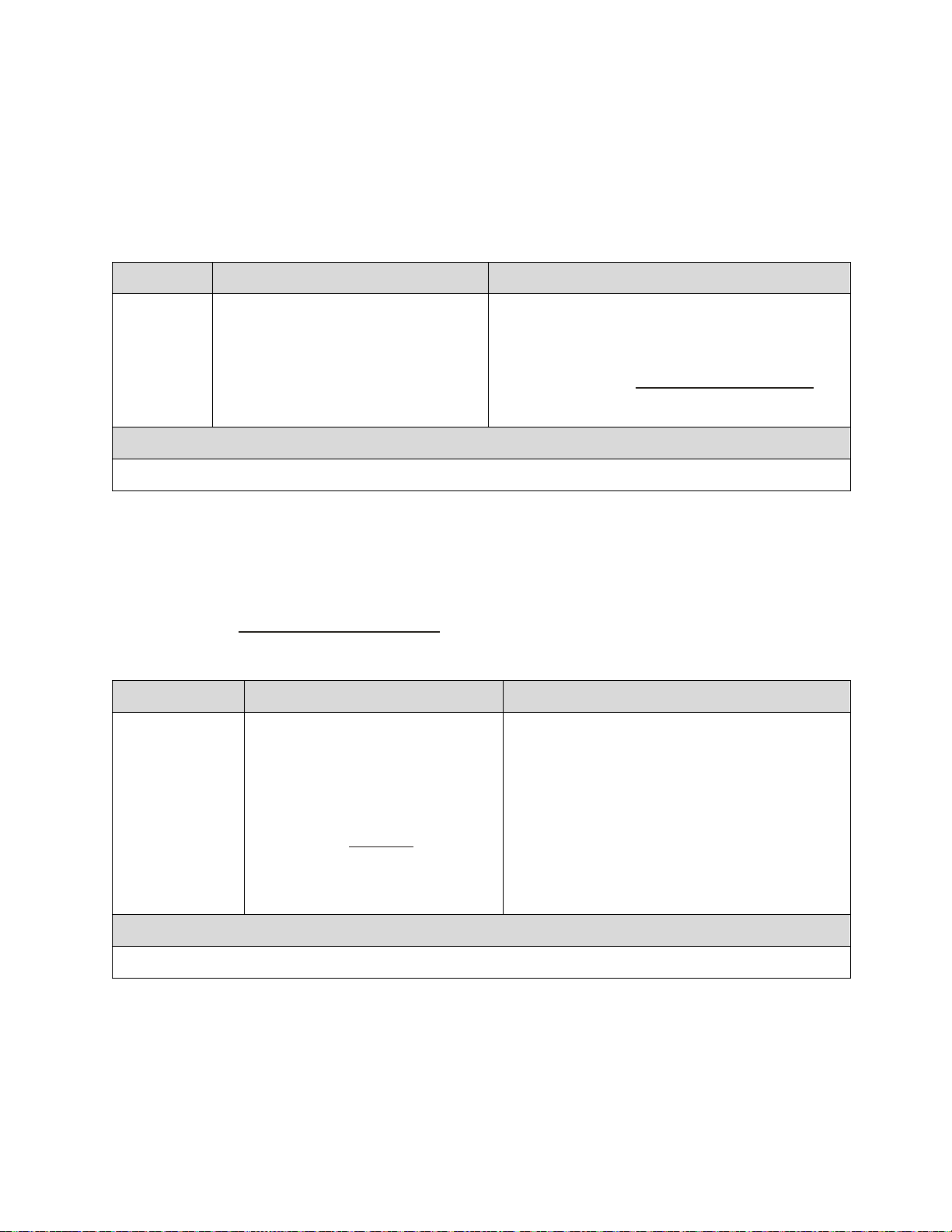
58 Spyder3 S3-14 and S3-24 Monochrome Camera User's Manual
Parameter
Description
Notes
ssb t i
t:
Tap selection. Allowable range is 1 to 2
depending on camera model, or 0 for all
taps.
i:
Subtracted value in a range in DN from 0
to 4095.
When subtracting a digital value from the digital
vid eo signal the output can no longer reach its
maximum. Use the ssg command to correct for
this where:
ssg value =
max output value
max output value - ssb value
Example
ssb 0 25
ssg value =
max output value
max output value - ssb value
Parameter
Description
Notes
ssg t i
t: Tap selection. Allowable range is 1
to 2, or 0 for all taps.
i:
Gain setting. The gain ranges are 0 to
65535. The digital video values are
multiplied by this value where:
Use this command in conjunction with
the ssb command.
Example
ssg 1 15
Digital Gain=
4096
i
Subtracting Background
Use the background subtract command after performing flat field correction if you want to improve your
image in a low contrast scene. It is useful for systems that process 8 bit data but want to take advantage of
th e camera’s 12 bit d igital p rocessin g ch ain . You sh ou ld try to m ake y our d ar kest pixel in the scene equal
to zero.
Camera Link Command
Setting Digital System Gain
Improves signal output swing after a background subtract. When subtracting a digital value from the digital video
signal, using the ssb command, the output can no longer reach its maximum. Use this command to correct for this
where:
Camera Link Command
03-032-20117-01 Teledyne DALSA

Spyder3 S3-14 and S3-24 Monochrome Camera User's Manual 59
Parameter
Description
Notes
dpc x1 x2
x1: Start pixel to display in a range
from 1 to sensor pixel count.
x2 End pixel to display in a range from
x1 to sensor pixel count.
This function returns all the current pixel
coefficients in the order FPN, PRNU, FPN,
PRN U … Th e cam era also retu rn s th e pixel
number with each coefficient.
Example
dpc 10 20
Parameter
Description
Notes
gfc i
The pixel number to read in a range
from 1 to sensor pixel count.
Example
gfc 10
Parameter
Description
Notes
gpc i
i The pixel number to read in a range
from 1 to sensor pixel count.
Example
gpc 10
Returning Calibration Results and Errors
Returning All Pixel Coefficients
Returns all th e cu r rent p ixel coefficients in t h e or d er FPN , PRN U, FPN , P RN U… for the r ange specified
by x1 and x2. The camera also returns the pixel number with every fifth coefficient.
Camera Link Command
Returning FPN Coefficients
Returns a p ixel’s FPN coefficient v a lu e in DN (12 bit LSB)
Camera Link Command
Returning PRNU Coefficients
Returns a p ixel’s PRN U coefficient v alu e in DN (12 bit LSB)
Camera Link Command
Teledyne DALSA 03-032-20117-01

60 Spyder3 S3-14 and S3-24 Monochrome Camera User's Manual
Parameter
Description
Notes
epc i i
i FPN coefficients.
0 = FPN coefficients disabled
1 = FPN coefficients enabled
i PRNU coefficients.
0 = PRNU coefficients disabled
1 = PRNU coefficients enabled
Example
epc 0 1
Parameter
Description
Notes
els i
0 Disable end-of-line sequence
1 Enable end-of-line sequence
LVAL is not high during the end -of-line
statistics.
Example
els 1
Location
Value
Description
1
A’s
By ensuring these values consistently toggle betw een "aa" and
"55", you can verify cabling (i.e. no stuck bits)
2
5’s
3
A’s
4
4 bit counter LSB justified
Counter increments by 1. Use this value to verify that every line
is output
5
Line sum (7…0)
Use these values to help calculate line average and gain
6
Line sum (15…8)
7
Line sum (23…16)
Enabling and Disabling Pixel Coefficients
Enables and disables FPN and PRNU coefficients
Camera Link Command
End-of-line Sequence
To aid in debugging, the camera can p roduce an end-of-line sequence that provides basic calculations
including "line counter", "line sum", "pixels above threshold", "pixels below threshold", and "derivative
line sum" within the region of interest. These calculations can be used to perform aoc algorithms or
indicate objects of interest.
To further aid in debugging and cable/ data path integrity, the first three pixels after Line Valid are "aa",
"55", "aa". Refer to the following table. These statistics are calculated for the pixels within the r egion of
interest.
Camera Link Command
Table 14: End-of-Line Sequence Description
03-032-20117-01 Teledyne DALSA

Spyder3 S3-14 and S3-24 Monochrome Camera User's Manual 61
Location
Value
Description
8
Line sum (31…24)
9
Pixels abov e th reshold (7…0)
Monitor these values (either above or below threshold) and
adjust camera digital gain and background subtract to maximize
scene contrast. This provides a basis for automatic gain control
(AGC)
10
Pixels above threshold
(15…8)
11
Pixels below threshold (7…0)
12
Pixels below threshold (15…8)
13
Differential line sum (7..0)
Use these values to focus the camera. Generally, the greater the
sum the greater the image contrast and better the focus.
14
Differen tial lin e sum (15…8)
15
Differen tial lin e sum (23…16)
16
Differen tial lin e sum (31…24)
Parameter
Description
Notes
sut i
Upper threshold limit in range from 0
to 4095.
LVAL is not high during the end-of-line statistics.
Example
sut 1024
Parameter
Description
Notes
slt i
Upper threshold limit in range from 0
to 4095.
LVAL is not high during the end -of-line statistics.
Example
slt 1024
Setting Thresholds
Setting an Upper Threshold
Sets the upper threshold limit to report in the end -of-line sequence.
Camera Link Command
Setting a Lower Threshold
Sets the lower threshold limit to report in the end-of-line sequence.
Camera Link Command
Teledyne DALSA 03-032-20117-01

62 Spyder3 S3-14 and S3-24 Monochrome Camera User's Manual
Parameter
Description
Notes
cil
0 to 1. 0 for dark, 1 for light.
This command calibrates all
taps within the ROI.
To calibrate:
Place a white reference in front of the camera. This is similar
to a PRNU calibration.
In addition:
Use the wil command to write the LUT to non-volatile
memory.
Use the eil command to enable use of the LUT.
Use the roi command to limit the taps calibrated and to limit
which pixels are used for calibration. If a tap is not in the
region of interest, then it will not be calibrated and left at
current values.
Press spacebar to abort this command.
Rerun this command if the analog gain or operating
temperature changes.
Example
Parameter
Description
Notes
eil flag
0 Disable
1 Enable
Coefficients must be created first w ith the cil command.
Setting saved with the wfs and w us commands.
Example
Look-Up Tables
Note: This information only applies to the 4k model camera.
The flat field corrections FPN and PRNU assume a linear response to the amount of light by the sensor,
output node, analog amplifier, and analog to digital converter. To correct any non -linearity in this system
of components a Look-Up Table (LUT) has been implemented in the FPGA for each tap immediately after
the ADC. The LUT adds a signed value (-256 to +255) indexed by the 10 MSB of the input value.
Calibrate Input LUT
Calibrates the current input look-up table for correcting non-linearity in the analog chain (CCD sense
node and analog-to-digital conversion).
Camera Link Command
Enable Input LUT
Enables or disables the use of the input look-up tables for the correction of the analog chain non-linearity.
Camera Link Command
03-032-20117-01 Teledyne DALSA

Spyder3 S3-14 and S3-24 Monochrome Camera User's Manual 63
Parameter
Description
Notes
wil
0 = Factory set
1 to 4 = User sets
LUT use is enabled or disabled with the
EIL command.
Set 0 can only be written from factory
mode.
Example
Parameter
Description
Notes
wpc i
PRNU coefficients set to save.
1 = Coefficient set one
2 = Coefficient set two
3 = Coefficient set three
4 = Coefficient set four
Example
wpc 2
Parameter
Description
Notes
wfc i
FPN coefficients set to save.
1 = Coefficient set one
2 = Coefficient set two
3 = Coefficient set three
4 = Coefficient set four
Write Input LUT
Saves current values of input LUT that are in FPGA SDRAM to Flash memory or a PC file.
Camera Link Command
Saving and Restoring PRNU and FPN
Coefficients
Saving the Current PRNU Coefficients
The wpc command saves the current PRNU coefficients. You can save up to four sets of pixel coefficients.
Camera Link Command
Saving the Current FPN Coefficients
The wfc command saves the current FPN coefficients. You can save up to four sets of pixel coefficients
Camera Link Command
Teledyne DALSA 03-032-20117-01

64 Spyder3 S3-14 and S3-24 Monochrome Camera User's Manual
Example
wfc 2
Parameter
Description
Notes
lpc i
FPN coefficients set to save.
0 = Factory calibrated pixel
coefficients.
1 = Coefficient set one
2 = Coefficient set two
3 = Coefficient set three
4 = Coefficient set four
Example
lpc 0
Parameter
Description
Notes
rpc
The digital offset is not reset.
Example
Loading a Saved Set of Coefficients
The lpc command Loads one of the 4 saved sets of pixel coefficients. In addition, a factory calibrated set
of coefficients is available.
Camera Link Command
Resetting the Current Pixel Coefficients
The rpc command resets the current pixel coefficients to zero. This command does not reset saved
coefficients.
Camera Link Command
Rebooting the Camera
The command rc reboots the camera. The camera starts up with the last saved settings and the baud rate
used before the reboot order. Previously saved pixel coefficients are also restored.
03-032-20117-01 Teledyne DALSA

Spyder3 S3-14 and S3-24 Monochrome Camera User's Manual 65
Parameter
Description
svm 0 Video.
svm
smm
1
0
12 bit test pattern.
2 tap model:
svm
smm
1
1
svm
smm
2
1
svm
smm
2
0
8 bit test pattern
2 tap model:
Diagnostics
Generating a Test Pattern
Use the svm command to generate a test pattern to aid in system debugging. The test patterns are useful
for verifying camera timing and connections. The following tables show each available test pattern.
Camera Link Command
Teledyne DALSA 03-032-20117-01

66 Spyder3 S3-14 and S3-24 Monochrome Camera User's Manual
svm
smm
2
1
svm
smm
1
0
12 bit test pattern
1 tap model:
svm
smm
1
1
svm
smm
2
1
8 bit test pattern
t tap model:
03-032-20117-01 Teledyne DALSA

Spyder3 S3-14 and S3-24 Monochrome Camera User's Manual 67
Parameter
Description
Notes
gl x1 x2
x1 Pixel start number. Must be less
than the pixel end number in a range
from 1 to sensor resolution.
x2 Pixel end number. Must be greater
than the pixel start number in a range
from 2 to sensor resolution.
If x2x1 then x2 is forced to be x1.
Values returned are in 12-bit DN.
Example
gl 10 20
Returning Video Information
The cam era’s m icrocon troller h as t h e ab ility to read vid eo d ata. This fu nction ality can be u sed to verify
camera operation and to perform basic testing without having to connect the camera to a frame grabber.
This information can also be used to collect line statistics for calibrating the camera.
Returning a Single Line of Video
Returns a complete line of video (without pixel coefficients applied) displaying one pixel value after another. After
pixel values have been displayed it also displays the minimum, maximum, and mean value of the line sampled
within the region of interest (the region of interest command is explained in section Setting a Region of Interest
(ROI)).
Use the gl command, or the following gla command, to ensure the proper video input range into the
processing chain before executing any pixel calibration commands.
Camera Link Command
Teledyne DALSA 03-032-20117-01

68 Spyder3 S3-14 and S3-24 Monochrome Camera User's Manual
Parameter
Description
Notes
css m
Number of lines to sample. Allowable
values are 256, 512, or 1024 (factory
setting).
To return the current setting, use the gcp
command or get css.
Example
css 1024
Parameter
Description
Notes
gla x1 x2
x1 Pixel start number. Must be less
than the column end number in a
range from 1 to sensor resolution.
x2 Pixel end number. Must be greater
than the column start number in a
range from 2 to column resolution.
If x2x1 then x2 is forced to be x1.
Analog gain, analog offset, digital offset,
background subtract, and digital system gain
are applied to the data. FPN and PRNU
coefficients are not included in the data.
Values returned are in 12 bit DN.
Example
gla 10 20
Returning Averaged Lines of Video
Setting the Number of Lines to Sample
The css command sets the number of lines to sample when using the gla command or when performing
an FPN or PRNU calibration.
Camera Link Command
Returning the Average of Multiple Lines of Video
The gla command returns the average for multiple lines of video data (without pixel coefficients applied).
The number of lines to sample is set and adjusted by the css command. The camera displays the Min.,
Max., and Mean statistics for the pixels in the region of interest (t he region of interest command is
explained in section Setting a Region of Interest (ROI)).
Camera Link Command
Temperature Measurement
The temperature of the camera can be determined by using the vt command. This command will return
the internal chip case temperature in degrees Celsius. For proper operation, this value should not exceed
65 °C.
Note: If the camera reaches 65 °C, the camera will shut down and the LED will flash red. If this occurs, the
camera must be rebooted using the command, rc or can be powered down manually. You will not be
able to restart the camera until the temperature is less than 65°C. You will have to correct the temperature
problem or the camera will shut down again. The camera allows you to send the vt (verify temperature)
command w hile it is in this state.
03-032-20117-01 Teledyne DALSA

Spyder3 S3-14 and S3-24 Monochrome Camera User's Manual 69
Parameter
Description
Notes
gsf i
Camera Link control signal to
measure:
1: CC1 (EXSYNC)
2: CC2 (PRIN)
3: CC3 (CCD Direction)
Camera operation may be impacted when
entering the gsf command (i.e., poor time
response to direction change or video may have
artifacts (gain changes) for several lines while
the camera returns signal information)
This command is not available when operating the
camera with external CCD direction control (scd
2)
Example
gsf 1
Voltage Measurement
The command vv d isp lays the cam era’s in pu t volta ge. Note th at the voltage mea su r ement featu re of th e
camera provides only approximate results (typically within 10%). The measurement should not be used
to set the applied voltage to the camera but only used as a test to isolate gross problems with the supply
voltage.
Camera Frequency Measurement
Returns the frequency for the requested Camera Link control signal
Camera Link Command
Teledyne DALSA 03-032-20117-01

70 Spyder3 S3-14 and S3-24 Monochrome Camera User's Manual
Mnemonic
Syntax
Parameters
Description
correction calibrate fpn
ccf
Performs FPN calibration and eliminates FPN noise by
subtracting away individual pixel dark current.
calculate camera gain
ccg
i t i
Calculates the camera gain according to the selected
algorithm.
i = Calibration algorithm to use.
1 = This algorithm adjusts analog gain so that 8% to
13% of tap ROI pixels are above the specified target
value.
2 = This algorithm adjusts analog gain so that the
aver age p ixel value in tap’s ROI is equ al to the
specified target value.
3 = This algorithm adjusts digital gain so that the
aver age p ixel value in tap’s ROI is equ al to the
specified target.
4= This algorithm adjusts the analog gain so that
the peak tap ROI pixels are adjusted to the specified
target.
t = Tap value. Use 0 for all taps or 1 or 2 for
individual tap selection depending on camera model.
i = Calibration target value in a range from 1024 to
4055 DN (12 bit LSB).
correction calibrate prnu
ccp
Performs PRNU calibration and eliminates the difference
in responsivity between the most and least sensitive
pixel creating a uniform response to light.
calibrate input LUT
cil
Calibrates the input lookup table (LUT). The LUTs are
used to remove nonlinearity from the analog chain.
Camera Link mode
clm
i m
Sets th e cam era’s bit w id th w h ere:
For S3-1x-01K40 and S3-1x-02K40
0 = 8 bits, 1 tap
1 = 12 bits, 1 tap
For S3-2x-01K40 and S3-2x-02K40
2 = 8 bits, 2 taps
3 = 12 bits, 2 taps
Parameters:
t = tap id i = integer value
f = float m = member of a set
s = string
x
= pixel column number
y
= pixel row number
Returning Camera Settings with Get Commands
You can also retu rn in div id ual cam era settings by inserting a ― get” in front of the command that you
want to query. If the command has a tap or pixel number parameter, you must also insert the tap number
or pixel number that you w ant to query. To view a help screen listing the following get commands, use
the command gh.
ASCII Commands: Reference
The following table lists all of th e camera’s availab le ASCII com m an d s. Refer to A p pend ix A for d etailed
information on using these ASCII commands.
Table 15: Command Quick Reference
03-032-20117-01 Teledyne DALSA

Spyder3 S3-14 and S3-24 Monochrome Camera User's Manual 71
Mnemonic
Syntax
Parameters
Description
calculate PRNU algorithm
cpa
i i
Performs PRNU calibration according to the selected
algorithm.
The first parameter is the algorithm where i is:
1 = Th is algorith m first a d ju sts each t ap’s an alog g ain so
that 8-13% of pixels within a tap are above the value
specified in the target value parameter. PRNU
calibration then occurs using the peak pixel in the region
of interest. (Identical to ccp)
2 = Calculates the PRNU coefficients using the entered
target value as shown below:
PRNU Coefficient =
Target
(AVG Pixel Value) - (FPN+ value)sdo
The calculation is performed for all sensor pixels but
warnings are only applied to pixels in the region of
interest. This algorithm is useful for achieving uniform
output across multiple cameras.
3 = This algorithm includes an analog gain adjustment
prior to PRNU calibration. Analog gain is first adjusted
so th at the p eak p ixel valu e in tap ’s ROI is within 97 to
99% of the specified target value. It then calculates the
PRNU coefficients using the target value as shown
below:
The calculation is performed for all sensor pixels but
warnings are only applied to pixels in the region of
interest. This algorithm is useful for achieving uniform
output across multiple cameras.
The second parameter is the target value to use in a
range from 1024 to 4055DN.
correction set sample
css
m
Sets the number of lines to sample when using the gla
command or when performing FPN and PRNU
calibration where m is 256, 512, or 1024
display gpio configuration
dgc
Display the current configuration of the GPIO connector
display input lut
dil
t a a
0 – 2 : 0 – 1023 : 0 - 1023
display pixel coeffs
dpc
x1 x2
Displays the pixel coefficients in the order FPN, PRNU,
FPN , P RN U, …
x1 = Pixel start number
x2= Pixel end number
in a range from 1 to 1024 or 2048
enable input LUT
eil
i
Enable input LUT, w here:
0: Off
1: On
enable (EXSYNC) jitter
ejt
i
0 – 1. This feature will prevent line-to-line output
variations due to EXYNC jitter at the maximum line rate.
end of line sequence
els
i
Sets the end-of-line sequence:
0: Off
1: On
enable noise correction
enc
i
0 – 1. Enables FIR filter in the output. The first two pixels
are not filtered.
PRNU Coefficient =
Target
(AVG Pixel Value ) - (FPN + value)sdo
i
i
i
Teledyne DALSA 03-032-20117-01

72 Spyder3 S3-14 and S3-24 Monochrome Camera User's Manual
Mnemonic
Syntax
Parameters
Description
enable pixel coefficients
epc
i i
Sets whether pixel coefficients are enabled or disabled .
The first parameter sets the FPN coefficients where i is:
0 = FPN coefficients disabled
1 = FPN coefficients enabled
The second parameter sets the PRNU coefficients where
i is:
0 = PRNU coefficients disabled
1 = PRNU coefficients enabled
enable shaft encoder
ese
i
0 - 1
enable watchdog
ewd
i
0 – 1. The watchdog subtracts excessive dark current at
line rates below 10 Hz.
get camera model
gcm
Reads the camera model number.
get camera parameters
gcp
Reads all of the camera parameters.
get camera serial
gcs
Read the camera serial number.
get camera version
gcv
Read the firmware version and FPGA version.
get exposure mode
gem
Retrieves the current camera exposure mode.
get exposure range
ger
get fpn coeff
gfc
x
Read the FPN coefficient
x = pixel number to read in a range from 1 – sensor
pixel count.
get help
gh
Returns all of th e av ailable ―g et‖ commands.
get input LUT
gil
Display the current LUT set number.
get line
gl
x x
Gets a line of video (without pixel coefficients applied)
displaying one pixel value after another and the
minimum, maximum, and mean value of the sampled
line.
x = Pixel start number
x = Pixel end number
in a range from 1 to sensor pixel count.
get line average
gla
x x
Read the average of line samples.
x = Pixel start number
x = Pixel end number
In a range from 1 to sensor pixel count.
get prnu coeff
gpc
x
Read the PRNU coefficient.
x = pixel number to read in a range from 1 – sensor
pixel count.
get signal frequency
gsf
i
Reads the requested Camera Link control frequency.
1 = EXSYNC frequency
2 = Spare
3 = Direction
03-032-20117-01 Teledyne DALSA

Spyder3 S3-14 and S3-24 Monochrome Camera User's Manual 73
Mnemonic
Syntax
Parameters
Description
get status led
gsl
Returns the current state of the cam era’s LED w here:
1 = Red
2 = Green
5 = Blinking green
6 = Blinking red
help
h
Display the online help. Refer to the Select Cable Camera
ASCII Command Help for details.
single command help
?
s
load pixel coefficients
lpc
i
Loads the previously saved pixel coefficients from nonvolatile memory where i is:
0 = Factory calibrated coefficients
1 = Coefficient set one
2 = Coefficient set two
3 = Coefficient set three
4 = Coefficient set four
load user set
lus
reset camera
rc
Resets the entire camera (reboot). Baud rate is not reset
and reboots w ith the value last used.
restore factory settings
rfs
Restores the cam era’s factor y settin gs. FPN and PRN U
coefficients reset to 0.
reset input LUT
ril
Sets the value of the current LUT to zero. Use wil to save
this setting.
region of interest
roi
x y x y
Sets the pixel range affected by the cag, gl, gla, ccf,
and ccp commands. The parameters are the pixel start
and end values (x) and the column start and end values
(y) in a range from 1 to sensor pixel count.
reset pixel coeffs
rpc
Resets the pixel coefficients to 0.
restore user settings
rus
Restores the camera's last saved user settings and FPN
and PRNU coefficients.
set analog gain
sag
t f
Sets the analog gain in dB.
t = tap selection, either 1 or 2 depending on camera
model, or 0 for all taps.
f= gain value specified from –10 to +10
set analog offset
sao
t i
Sets the analog offset.
t = tap selection, either 1 or 2 depending on camera
model, or 0 for all taps.
i= Offset value in a range from 0 to 255 (12-bit LSB).
Offset increases with higher values.
set binning horizontal
sbh
m
Sets the horizontal binning value. Available values are 1
and 2.
set baud rate
sbr
i
Set the speed of camera serial communication port. Baud
rates: 9600, 19200, 57600, and 115200. Default: 9600.
set cable parameter
scb
i
Set the cable parameter. Output compare value.
Available values are: 0-255.
Teledyne DALSA 03-032-20117-01

74 Spyder3 S3-14 and S3-24 Monochrome Camera User's Manual
Mnemonic
Syntax
Parameters
Description
set ccd direction
scd
i
Sets the CCD shift direction where:
0 = Forward CCD shift direction.
1 = Reverse CCD shift direction.
2 = Externally controlled direction control via CC3.
(CC3=1 forward, CC3=0 reverse.)
set digital offset
sdo
t i
Subtracts the input value from the video signal prior to
FPN correction.
t = tap selection, either 1 or 2 depending on camera
model, or 0 for all taps.
i = Offset in a range from 0 to 2048DN.
set exposure mode
sem
m
Sets the exposure mode:
2 = Internal SYNC, internal PRIN, programmable line
rate and exposure time using commands ssf and set
3 = External SYNC, internal PRIN, maximum exposure
time
4 = Smart EXSYN C
5 = External SYNC and PRIN
6 = External SYNC, internal PRIN, programmable
exposure time
7 = Internal programmable SYNC, maximum exposure
time. Factory setting.
8 = Internal SYNC, internal PRIN, programmable
exposure time. Maximum line rate for exposure time.
set exposure time
set
f
Sets the exposure time. Refer to the camera help screen
(h command) for allow able range.
set fpn coeff
sfc
x i
Set the FPN coefficient.
x =pixel number within the range 1 to sensor pixel
count.
i= FPN value within the range 0 to 2047 (12-bit LSB).
set input LUT
sil
t i
Set a single value in a LUT.
t=Tap: 1 or 2.
i=Value w ithin the range -255 to +256.
set lower threshold
slt
i
The pixels below the low er threshold are checked for
and reported in the end-of-line sequence in a range from
0-4095.
set mirroring mode
smm
i
0 - 1
set prnu coeff
spc
x i
Set the PRNU coefficient.
x=pixel number within the range 1 to sensor pixel
count.
i= PRNU value within the range 0 to 28671.
set readout mode
srm
i
Set the readout mod e in order to clear out dark current
charge in the vertical transfer gates before the sensor is
read out.
0 = Auto.
1 = Dark current clear.
2 = Immediate readout. Does not clear dark current.
set subtract background
ssb
t i
Subtract the input value from the output signal.
t = Tap value. 0 for all taps or 1 to number of camera taps
for individual tap selection.
i = Subtracted value in a range from 0 to 4095.
03-032-20117-01 Teledyne DALSA

Spyder3 S3-14 and S3-24 Monochrome Camera User's Manual 75
Mnemonic
Syntax
Parameters
Description
set sync frequency
ssf
i
Set the frame rate to a value from 300Hz to 36000Hz
(2k model) or 300Hz to 68000Hz (1k model). Value
rounded up/ dow n as required.
set system gain
ssg
t i
Set the digital gain.
t = tap selection, either 1 to 2, or 0 for all taps
i = Digital gain in a range from 0 to 65535. The digital
vid eo values are multiplied by this number.
set sensitivity mode
ssm
i
Sets th e cam era’s sensitiv ity m od e w h ere i is:
0 = Low sensitivity mode
1 = High sensitivity mode
2 = Tall pixel mode
set upper threshold
sut
i
The pixels equal to or greater than the upper threshold
are checked for and reported in the end -of-line sequence
in a range from 0-4095.
set video mode
svm
i
Switch between normal video mode and camera test
patterns:
0: Normal video mode
1: Camera test pattern
2: Camera test pattern
update gain reference
ugr
Changes 0dB gain to equal the current analog gain value
set with the sag command.
verify temperature
vt
Check the internal temperature of the camera
verify voltage
vv
Ch eck the cam era’s inp u t voltag es and r etu rn OK or fail
write FPN coefficients
wfc
i
Write all current FPN coefficients to non-volatile
memory, where i is:
1 = FPN coefficient set one
2 = FPN coefficient set two
3 = FPN coefficient set three
4 = FPN coefficient set four
write input LUT
wil
i
Wr ite cu r r en t LUT’s to no n -volatile memory.
i=1 to 4
write PRNU coeffs
wpc
i
Write all current PRNU coefficients to non-volatile
memory, where i is:
1 = PRNU coefficient set one
2 = PRNU coefficient set two
3 = PRNU coefficient set three
4 = PRNU coefficient set four
write user settings
wus
Write all of the user settings to non-volatile memory.
Message
Description
OK>
SUCCESS
Error Handling
The following table lists warning and error messages and provides a description and possible cause.
Warning messages are returned when the camera cannot meet the full value of the request; error
messages are returned w hen the camera is unable to complete the request.
Table 16: Warning and Error Messages
Teledyne DALSA 03-032-20117-01

76 Spyder3 S3-14 and S3-24 Monochrome Camera User's Manual
Message
Description
Warning 01: Outside of specification>
Parameter accepted was outside of specified operating range (e.g. gain
greater than ±10 dB of factory setting).
Warning 02: Clipped to min>
Parameter was clipped to the current operating range. Use gcp to see
value used.
Warning 03: Clipped to max>
Parameter was clipped to the current operating range. Use gcp to see
value used.
Warning 04: Related parameters adjusted>
Parameter was clipped to the current operating range. Use gcp to see
value used.
Warning 07: Coefficient may be inaccurate
A/ D clipping has occurred>
In the region of interest (ROI) greater than 6.251% single or 1% of
averaged pixel values were zero or saturated.
Warning 08: Greater than 1% of coefficients
have been clipped>
A FPN/ PRNU has been calculated to be greater than the maximum
allowable 511 (8).
Warning 09: Internal line rate inconsistent
with readout time>
Message
Description
Error 02: Unrecognized command>
Command is not available in the current access level or it is not a valid
command.
Error 03: Incorrect number of parameters>
Error 04: Incorrect parameter value>
This response returned for
· Alpha received for numeric or vice versa
· Not an element of the set of possible values. E.g., Baud Rate
· Outside the range limit
Error 05: Command unavailable in this
mode>
Command is valid at this level of access, but not effective. Eg line rate
when in smart Exsync mode
Error 06: Timeout>
Command not completed in time. Eg FPN/ PRNU calculation when no
external Exsync is present.
Error 07: Camera settings not saved>
Tried saving camera settings (rfs/ rus) but they cannot be saved.
Error 08: Unable to calibrate - tap outside
ROI>
Cannot calibrate a tap that is not part of the region of interest.
Error 09: The camera's temperature exceeds
the specified operating range>
Indicates that the camera has shut itself down to prevent damage from
further overheating.
03-032-20117-01 Teledyne DALSA

Spyder3 S3-14 and S3-24 Monochrome Camera User's Manual 77
0Hz
Watchdog
Frequency
Max. Line Rate in
Immediate
Readout Mode
Increasing Line Rate
Frequency
Dark Current
Clear
Immediate
Readout
Dark
Current
Clear to
Immediate
Readout
Transition
Frequency
Immediate
Readout to
Dark
Current
Clear
Transition
Frequency
Max. Line Rate in
Dark Current Clear
Mode
Mode
Transition Frequencies
Model
Dark Current Clear to Immediate Readout
Transition
Immediate Readout to Dark
Current Clear Transition
S3-14-01k40
13.6KHz
16.4KHz
S3-24-01k40
25.1KHz
30.4KHz
Appendix A
Clearing Dark Current
Gate Dark Current Clear
Note: This feature is not available for the S3-24-04k40 camera model.
Image sensors accumulate dark current while they wait for a trigger signal. If the readout is not triggered
in a reasonable amount of time, then this dark current accumulation may increase to an excessive
amount. The result of this happening will be that the first row, and possibly additional rows (frames), of
the image will be corrupt.
The sensor used in this camera contains two sources of dark current that will accumulate with time: 1) in
the photo sensitive area, and 2) in the gates used to clock-out the charge.
The gate dark current can account for approximately 20% of the total dark current present. While the
exposure control has direct control over the amount of dark current in the photo sensitive area, it has no
control over the charge accumulated in the gates. Even with exposure control on, at low line rates, this
gate charge can cause the camera to saturate.
Using the Set Readout Mode (srm) command, the camera user can control the camera's behavior in
order to minimize the dark current artifact.
The modes of operation selected by the srm command are: Auto, On, or Off.
Note: This command is only available in low sensitivity and tall pixel modes. High sensitivity mode
operates only in the immediate read out position.
Figure 28: Gate Dark Current Clear
Table 17.
Teledyne DALSA 03-032-20117-01

78 Spyder3 S3-14 and S3-24 Monochrome Camera User's Manual
S3-14-02k40
7.05KHz
8.52KHz
S3-24-02k40
13.6KHz
16.4KHz
S3-24-04k40
4.4KHz
7.24KHz
Max. Line Rate
Model
Immediate Readout
Mode
Dark Current Clear
Mode
S3-14-01k40
36 KHz
18KHz
S3-24-01k40
68 KHz
34 KHz
S3-14-02k40
18.5KHz
9.25KHz
S3-24-02k40
36 KHz
18 KHz
S3-24-04k40
18.5KHz
9.25KHz
Model
Exposure Delay and Max Exposure Time in Auto
Mode
S3-14-01k40
27.5 µs
S3-24-01k40
14.75 µs
S3-14-02k40
53.1µs
S3-24-02k40
27.5 µs
S3-24-04k40
53.1µs
Immediate read out mode (default, srm 2)
In this mode the image is read out, including accumulated dark current, immediately following the
trigger or the EXSYNC falling edge.
There are no line rate limitations other than the amount of gate dark current that can be tolerated at low
line rates.
There are no timing or exposure anomalies other than situations where EXSYNC is removed from
camera. In this case, the camera will operate in a "watchdog" state.
For information on artifacts that may be experienced while using this mode, see the Artifacts section
below.
Gate dark current clear mode (always on, srm 1)
In this mode the gate dark current will be cleared continuously.
After the trigger (EXSYNC) is received, the dark current is cleared from the image sensor before the
image is acquired. The line rate is limited to ½ the maximum line rate available for that model of camera.
For information on artifacts that may be experienced while using this mode, see the Artifacts section
below.
Table 18.
When operating in the dark current clear mode, there will be a slight delay, equivalent to one readout
time, before the actual exposure is implemented. The actual exposure time will not be altered.
Table 19.
03-032-20117-01 Teledyne DALSA

Spyder3 S3-14 and S3-24 Monochrome Camera User's Manual 79
Auto Mode (srm 0)
Note: This feature is not available for the S3-24-04k40 camera model.
In this mode the line rate from the camera will automatically cause a switch between the gate dark
current clear mode and non gate dark current clear mode.
The frequency of when this mode switchover occurs depends on the camera model.
In cases where the line rate is rapidly increased from below the Dark Current Clear to Immediate
Readout Transition Frequency to above the Immediate Readout to Dark Current Clear Transition
Frequency, the first line following this transition will likely be corrupted.
The table below outlines the artifacts that may be seen during this transition period. All subsequent lines
after this occurrence will be as expected.
In the case of a slow transition (that is, when the EXSYNC line rate increases by less than 10% of the
previous line rate) a line readout will not become corrupt.
There are also limitations on the exposure time when operating in auto mode: If the line rate exceeds half
the maximum line rate, then the exposure time cannot exceed the time stated in Table 19.
Note: Teledyne DALSA recommends Auto mode for most users.
For information on artifacts that may be experienced while using this mode, see the Artifacts section
below.
Please note: The graphic below explains the relationship between the following tables an d the preceding
Figure 28. The operating regions described in the tables refer to a specific region of Figure 28.
Dark Current Dump to Immediate Readout: Multi-Line Artifacts.
Teledyne DALSA 03-032-20117-01

80 Spyder3 S3-14 and S3-24 Monochrome Camera User's Manual
SRM 0, Auto Mode.
Time Period
Operating Region
Refer to Figure 28.
Operating Mode
T0 Dark Current Dump state
T1 Immediate Readout state
SRM 0, Auto Mode.
Time Period
Operating Region
Refer to Figure 28.
Operating Mode
T0 Immediate Readout state
T1 Dark Current Dump state
T2 Immediate Readout state
SRM 2, Immediate Readout Mode.
Time Period
Operating Region
Refer to Figure 28.
Operating Mode
T0 Dark Current Dump state
T1 Immediate Readout state
EXSYNC
T
DUMP
T
INT
LVAL
Valid
F
DUMP
F
IMM EDIATE
Dark Current Dump to Immediate Readout (T
INT
< #)
03-032-20117-01 Teledyne DALSA

Spyder3 S3-14 and S3-24 Monochrome Camera User's Manual 81
T
VERT_TRANS
F
DUMP
LVAL
F
IMM EDIATE
Valid
EXSYNC
T
DUMP
T
INT
SRM 0, Auto Mode.
Time Period
Operating Region
Refer to Figure 28.
Operating Mode
T0 Dark Current Dump state
T1 Immediate Readout state
SRM 0, Auto Mode.
Time Period
Operating Region
Refer to Figure 28.
Operating Mode
T0 Immediate Readout state
T1 Dark Current Dump state
T2 Immediate Readout state
SRM 2, Immediate Readout Mode.
Time Period
Operating Region
Refer to Figure 28.
Operating Mode
T0 Dark Current Dump state
T1 Immediate Readout state
Dark Current Dump to Immediate Readout (T
INT
> #)
Dark Current Dump to Immediate Readout: Multi-Line Artifacts
Teledyne DALSA 03-032-20117-01

82 Spyder3 S3-14 and S3-24 Monochrome Camera User's Manual
Valid
T
VERT_TRANS
LVAL
EXSYNC
T
DUMP
T
INT
F
DUMP
> DU MP (MAX)
F
Valid
EXSYNC
T
DUMP
T
INT
T
VERT_TRANS
LVAL
F
DUMP
> DU MP (MAX)
F
SRM 0, Auto Mode.
Time Period
Operating Region
Refer to Figure 28.
Operating Mode
T0 Immediate Readout state
T1 Dark Current Dump state
SRM 0, Auto Mode.
Time Period
Operating Region
Refer to Figure 28.
Operating Mode
T0 Dark Current Dump state
T1 Immediate Readout state
T2 Dark Current Dump state
Dark Current Dump to Immediate Readout (T
INT
< #)
Dark Current Dump to Immediate Readout (T
INT
> #)
Immediate Readout to Dark Current Dump: Hysteresis Artifacts
03-032-20117-01 Teledyne DALSA

Spyder3 S3-14 and S3-24 Monochrome Camera User's Manual 83
F
DUMP
F
IMM EDIATE
Valid
EXSYNC
T
DUMP
T
INT
T
VERT_TRANS
LVAL
Teledyne DALSA 03-032-20117-01

84 Spyder3 S3-14 and S3-24 Monochrome Camera User's Manual
Parameter
Description
Notes
srm
0: Auto. Clears dark current below ~
45% of the maximum line rate. (1k and
2k camera models only.)
1: Dark current clear. Always clears
dark. Reduces the maximum line rate.
(1k and 2k camera models only.)
2: Immediate readout. Does not clear
dark current. (Default mode.)
Modes 0 and 1 are not available to the 4k camera
model.
The vertical transfer gates collect dark current
during the line period. This collected current is
added to the pixel charge. The midd le two red
taps have more vertical transfer gates and,
therefore, more charge. This additional charge is
especially noticeable at slower line rates.
If the user is in sem 2 or 7 and srm 2, with
ssf at 45% of the maximum, and then srm 1 is
selected, the following warning will be
displayed, but the ssf value will not be changed:
Warning 09: Internal line rate inconsistent with
readout time> The effect in both internal and
external line rate modes is that an EXSYNC is
skipped and, therefore, the output will be at
least twice as bright.
This value is saved with the camera settings.
This value may be viewed using either the gcp
command or the get srm command.
Example
srm 0
Setting the Readout Mode
Use this command to clear out dark current charge in the vertical transfer gates immediately before the
sensor is read out.
Camera Link Command
03-032-20117-01 Teledyne DALSA

Spyder3 S3-14 and S3-24 Monochrome Camera User's Manual 85
Appendix B
Camera Link Reference, Timing, and
Configuration Table
Camera Link is a communication interface for vision applications. It provides a connectivity standard
between cameras and frame grabbers. A st and ard cable con n ection w ill red uce manu facturers’ sup p or t
time and greatly reduce the level of complexity and time needed for customers to successfully integrate
high speed cameras with frame grabbers. This is particularly relevant as signal and data transmissions
increase both in complexity and throughput. A stand ard cable/ conn ector assembly will also enable
customers to take advantage of volume pricing, thus reducing costs.
The camera link standard is intended to be extremely flexible in order to meet the needs of different
camera and frame grabber manufacturers.
The Teledyne DALSA Camera Link Implementation Road Map (available here) details how Teledyne
DALSA stand ardizes its use of the Camera Link interface.
LVDS Technical Description
Low Voltage Differential Signaling (LVDS) is a high speed, low power, general purpose interface
standard. The standard, known as ANSI/ TIA/ EIA-644, was approved in March 1996. LVDS uses
differential signaling, with a nominal signal swing of 350mV differential. The low signal swing decreases
rise and fall times to achieve a theoretical maximum transmission rate of 1.923 Gbps into a loss-less
medium. The low signal swing also means that the standard is not dependent on a particular supply
voltage. LVDS uses current-mode drivers, which limit power consumption. The differential signals are
immune to ±1 V common volt noise.
Camera Signal Requirements
This section provides definitions for the signals used in the Camera Link interface. The standard Camera
Link cable provides camera control signals, serial communication, and video data.
Video Data
The Channel Link technology is integral to the transmission of video data. Image data and image enable
signals are transmitted on the Channel Link bus. Four enable signals are defined as:
• FVAL—Frame Valid (FVAL) is defined HIGH for valid lines.
• LVAL—Line Valid (LVAL) is defined HIGH for valid pixels.
• DVA L—Data Valid (DVAL) is defined HIGH when data is valid.
• Spar e— A spare has been defined for future use.
All four enable signals must be provided by the camera on each Channel Link chip. All unused data bits
must be tied to a known value by the camera. For more information on image data bit allocations, refer to
the official Camera Link specification located in the Knowledge Center on Teled y n e DA LSA’s website .
Teledyne DALSA 03-032-20117-01

86 Spyder3 S3-14 and S3-24 Monochrome Camera User's Manual
CC1
EXSYNC, negative edge active
CC2
PRIN
CC3
Direct in High Sensitivity mode
CC4
Not Used
BASE
Configuration
T0
Mode
Port A
Bits 0 thru
7
Port B
Bits 0 thru
7
Port C
Bits 0 thru
7
Mode 0
1 Tap 8 bit
Tap 1
LSB..Bit 7
xxxxxxx
xxxxxxx
Camera Control Signals
Four LVDS pairs are reserved for general purpose camera control. They are defined as camera inputs and
frame grabber outputs. Camera manufacturers can define these signals to meet their needs for a
particular product. The signals are:
• Cam era C ontr ol 1 (CC1)
• Cam era C ontr ol 2 (CC2)
• Cam era C ontr ol 3 (CC3)
• Cam era C ontr ol 4 (CC4)
The S3-xx uses the following camera control signals:
Table 20: Teledyne DALSA Camera Control Configuration
Communication
Two LVDS pairs have been allocated for asynchronous serial communication to and from the camera and
frame grabber. Cameras and frame grabbers should support at least 9600 baud. These signals are
• SerTFG—Differential pair with serial communications to the frame grabber.
• SerTC—Differential pair with serial communications to the camera.
The serial interface will have the following characteristics: one start bit, one stop bit, no parity, and no
handshaking. It is recommended that frame grabber manufacturers supply both a user interface and a
software application programming interface (API) for using the asynchronous serial communication port.
The user interface will consist of a terminal program with minimal capabilities of sending and receiving a
character string and sending a file of bytes. The software API will provide functions to enumerate boards
and send or receive a character string.
Power
Power will not be provided on the Camera Link connector. The camera will receive power through a
separate cable. Camera manufacturers will define their own power connector, current, and voltage
requirements.
Camera Link Bit Definitions
03-032-20117-01 Teledyne DALSA

Spyder3 S3-14 and S3-24 Monochrome Camera User's Manual 87
Mode 1
1 Tap n bit
Where
n=10,12
Tap 1
LSB..Bit 7
Tap 1 Bits
8,9,10,11,
xxxxxxx
Mode 2
2 Tap 8 bit
Tap 1
LSB..Bit 7
Tap 2
LSB..Bit7
xxxxxxx
Mode 3
2 Tap n bit
Where
n=10,12
Tap 1
LSB..Bit 7
Tap 1 Bits
8,9,10,11,
Tap 2 Bits
8,9,10,11
Tap 2
LSB..Bit 7
Camera Link Configuration Tables
The following table provides tap reconstruction information. Teledyne DALSA is working with the
machine vision industry to use this table as the basis for auto configuration. Visit the Knowledge Center
on our website, and view the Teledyne DALSA Camera Link Implementation Road Map document, 0332-00450, for further details.
Teledyne DALSA 03-032-20117-01

88 Spyder3 S3-14 and S3-24 Monochrome Camera User's Manual
Item (when
programmable
configuration the
options are
separated with a | )
S3-14-01k40
S3-24-01k40
S3-14-02k40
S3-24-02k40
S3-24-04k-40
Imager Dimension <1,2
or 1| 2>
1 1 1 1 1
Imager
Columns<number of
active columns, X>
1024
1024
2048
2048
4096
Imager Rows<number of
active row s, Y> Line
Scan/ TDI are defined as
1
1 1 1 1 1
Number of CCD Taps
<1,2,3…..>
1 2 1 2 2
Sensor Tap Clock Rate
<xx MHz>
40
40
40
40
40
Camera Standard
<NTSC, PAL, VS, VW,
MW>
VS
VS
VS
VS
VS
Variable Window
<Column Start, Column
End, Row Start, Row
End>
(0,0,0,0)
All zeros
indicates an
unsupported
feature
(0,0,0,0)
All zeros
indicates an
unsupported
feature
(0,0,0,0)
All zeros
indicates an
unsupported
feature
(0,0,0,0)
All zeros
indicates an
unsupported
feature
(0,0,0,0)
All zeros
indicates an
unsupported
feature
Multiple Window
Number of Windows
(Column Start 1, Column
End 1, Row Start 1, Row
End 1) (Column Start 2,
Column End 2,...)
0, (0,0,0,0)
All zeros
indicates an
unsupported
feature
0, (0,0,0,0)
All zeros
indicates an
unsupported
feature
0, (0,0,0,0)
All zeros
indicates an
unsupported
feature
0, (0,0,0,0)
All zeros
indicates an
unsupported
feature
0, (0,0,0,0)
All zeros
indicates an
unsupported
feature
Number of Camera
Configuration s<1,2,3,…>
2 2 2 2 2
Configuration Definition
Cx= HDW, Number of
Output Taps, Bit Width,
Number of Processing
Nodes where
Cx is the configuration ID
x is <1,2,3…>
HDW is <Base,
Medium, Full>
Number of Output Taps
is <1,2,3…>
Bit width is <8, 10,
12…>
Number Processing
Nodes is <1 or 2>
C1 = Base, 1, 8, 1
C2 = Base, 1, 12, 1
C1 = Base, 2, 8, 1
C2 = Base, 2, 12,
1
C1 = Base, 1, 8, 1
C2 = Base, 1, 12,
1
C1 = Base, 2, 8, 1
C2 = Base, 2, 12, 1
C1 = Base, 2, 8,
1
C2 = Base, 2, 12,
1
Camera Interface Parameters (PRELIMINARY)
Table 21: Frame Grabber Interface Parameters
03-032-20117-01 Teledyne DALSA

Spyder3 S3-14 and S3-24 Monochrome Camera User's Manual 89
Item (when
programmable
configuration the
options are
separated with a | )
S3-14-01k40
S3-24-01k40
S3-14-02k40
S3-24-02k40
S3-24-04k-40
Tap Reconstruction
In some configurations
the reconstruction may
change. C0 is the default
output format and must
be listed. Output
con fig u r ation s t h at d on ’t
conform are listed
separately.
<Cx,Tn (Column Start,
Column End, Column
Increment, Row Start,
Row End, Row
Increment>
Horizontal
mirroring is
supported. Mirror
―on‖ ch a n ges th e
following
unmirrored
values to:
The sign of
the column
increment is
inverted.
Column Start
becomes the
Column End
value
Column End
becomes the
Column Start
value
Direction left to
right readout
C0, T1 (1, 1024, 1,
1, 1, 1)
Horizontal
mirroring is
supported.
Mir r or ―on ‖
changes the
following
unmirrored
values to:
The sign of
the column
increment is
inverted.
Column
Start
becomes the
Column
End value
Column
End
becomes the
Column
Start value
Direction left to
right readout
C0, T1 (1, 512, 1,
1, 1, 1)
C0, T2 (513,
1024, 1, 1, 1, 1)
Horizontal
mirroring is
supported.
Mir r or ―on ‖
changes the
following
unmirrored
values to:
The sign of
the column
increment is
inverted.
Column
Start
becomes the
Column
End value
Column
End
becomes the
Column
Start value
Direction left to
right readout
C0, T1 (1, 2048,
1, 1, 1, 1)
Horizontal
mirroring is
supported.
Mir r or ―on ‖
changes the
following
unmirrored
values to:
The sign of
the column
increment is
inverted.
Column
Start
becomes the
Column
End value
Column
End
becomes the
Column
Start value
Direction left to
right readout
C0, T1 (1, 1024,
1, 1, 1, 1)
C0, T2 (1025,
2048, 1, 1, 1, 1)
Horizontal
mirroring is
supported.
Mir r or ―on ‖
changes the
following
unmirrored
values to:
The sign of
the column
increment is
inverted.
Column
Start
becomes the
Column
End value
Column
End
becomes the
Column
Start value
Direction left to
right readout
C0, T1 (1, 2048,
1, 1, 1, 1)
C0, T2 (2049,
4096, 1, 1, 1, 1)
Camera Color
<Hybrid, Mono, Pattern,
Solid>
Mono
Mono
Mono
Mono
Mono
RGB Pattern Size
< (T1, Columns*Rows)
(T2, Columns*Rows) (T3,
Colu m n s*Row s….>
(T0, 1*1) w here 0
is reserved for the
default case and
individual taps
don’t need to be
articulated
(T0, 1*1) w here 0
is reserved for
the default case
and individual
taps d on’t n eed
to be articulated
(T0, 1*1) w here 0
is reserved for
the default case
and individual
taps d on’t n eed
to be articulated
(T0, 1*1) w here 0
is reserved for
the default case
and individual
taps d on’t n eed
to be articulated
(T0, 1*1) w here 0
is reserved for
the default case
and individual
taps d on’t n eed
to be articulated
Color Definition
(Column, Row, Color)
Where color is R,G,B
T0 = (1, 1, M)
where 0 is
reserved for the
default case and
individual taps
don’t need to be
defined
T0 = (1, 1, M)
where 0 is
reserved for the
default case and
individual taps
don’t need to be
defined
T0 = (1, 1, M)
where 0 is
reserved for the
default case and
individual taps
don’t need to be
defined
T0 = (1, 1, M)
where 0 is
reserved for the
default case and
individual taps
don’t need to be
defined
T0 = (1, 1, M)
where 0 is
reserved for the
default case and
individual taps
don’t need to be
defined
Row Color Offset
<0,1,2,3…>
0 0 0 0 0
Column Color Offset
<0,1,2,3…>
0 0 0 0 0
Row Binning Factor
<1,2,3 or 1| 2| 3>
1 1 1 1 1
Teledyne DALSA 03-032-20117-01

90 Spyder3 S3-14 and S3-24 Monochrome Camera User's Manual
Item (when
programmable
configuration the
options are
separated with a | )
S3-14-01k40
S3-24-01k40
S3-14-02k40
S3-24-02k40
S3-24-04k-40
Column Binning Factor
<1,2,3 or 1| 2| 3>
1| 2
1| 2
1| 2
1| 2
1| 2
Pretrigger Pixels
<0,1,2…or 0..15>
0 0 0 0 0
Pretrigger Lines
<0,1,2.. or 0..15>
0 0 0 0 0
Frame Time Minimum
<xx µs>
27.78
14.7
54.05
27.78
54.05
Frame Time Maximum
<xx µs>
3333
3333
3333
3333
3333
Internal Line/ Frame
Time Resolution
<xx ns> 0 if not
applicable
25
25
25
25
25
Pixel Reset Pulse
Minimum Width
<xx ns> 0 if not
applicable
3000
3000
3000
3000
3000
Internal Pixel Reset Time
Resolution
<xx ns> 0 if not
applicable
25
25
25
25
25
Pixel Reset to Exsync
Hold time <xx ns>
TBD
BAUD Rate <9600….>
9600, 19200,
57600, 115200
9600, 19200,
57600, 115200
9600, 19200,
57600, 115200
9600, 19200,
57600, 115200
9600, 19200,
57600, 115200
CC1 <Exsync>
EXSYNC
EXSYNC
EXSYNC
EXSYNC
EXSYNC
CC2 <PRIN>
PRIN
PRIN
PRIN
PRIN
PRIN
CC3 <Forward,
Reverse>
Forward/
Reverse
Forward/
Reverse
Forward/
Reverse
Forward/
Reverse
Forward/
Reverse
CC4 <Spare>
Spare
Spare
Spare
Spare
Spare
DVAL out <Strobe
Valid , Alternate>
Strobe Valid
Strobe Valid
Strobe Valid
Strobe Valid
Strobe Valid
Spare out <Spare>
(For future use)
Spare
Spare
Spare
Spare
Spare
03-032-20117-01 Teledyne DALSA

Spyder3 S3-14 and S3-24 Monochrome Camera User's Manual 91
Appendix C
EMC Declaration of Conformity
We, TELEDYNE DALSA
605 McMurray Road
Waterloo, Ontario
CANADA N2V 2E9
Declare under sole responsibility that the cameras:
Brand Name: Spyder3 CL
Models:S3-14-01K40-00-R, S3-24-01K40-00-R, S3-14-02K40-00-R, S3-24-02K40-00-R, and S3-24-04k40-00-R
The CE Mark, FCC Part 15, and Industry Canada ICES-003, CISPR 22 and CISPR 11, evaluation of the
Teledyne DALSA Spyder3 CL cameras, which are manufactured by Teledyne DALSA Inc., satisfied the
following requirements:
EN 55022 Class A (2006), and EN 61326-1 (2006) Emissions Requirements
EN 55024 (1998) and EN 61326-1 (2006) Immunity to Disturbances
Place of issue: Waterloo, Ontario, Canada
Date of Issue: March 15, 2008
Hank Helmond
Director of Quality, TELEDYNE DALSA Corp.
Teledyne DALSA 03-032-20117-01

92 Spyder3 S3-14 and S3-24 Monochrome Camera User's Manual
Number
Description
Date
00
Preliminary release.
23 February 2012
01
Revision to the Clearing Dark Current section.
Revised EMC Declaration section.
June 10, 2013
Revision History
03-032-20117-01 Teledyne DALSA

Spyder3 S3-14 and S3-24 Monochrome Camera User's Manual 93
Index
A
C
analog
processing, 48
applications, 7
calibrating the camera, 51, 54,
57
camera
control configuration, 86
messages, 75
camera control signals, 22, 86
Camera Link
configurations, 21, 33
connector, 21
mode, 34, 45
outputs, 23
signals, 86
camera settings. See settings
CameraLink mode, 34
certifications, 10
cleaning
sensor window, 6
clocking signals, 23
command
format, 27
parameters, 27
commands
list, 70
conectors
Camera Link, 21
connectors, 18
Camera Link, 21
Hirose, 19
power, 19
E
EIA-644 Reference, 85
electrical
specs, 8
EMC Compliance Standards,
10
EMC Declaration of
Conformity, 91
error messages, 75
exposure mode
overview, 39
setting, 39
timing, 40
EXSYNC, 22
external trigger, 22
F
factory settings, 29
flat field correction
restrictions, 52
framegrabber parameters, 88
FVAL, 23, 85
G
gain, 7, 49
GUI
overview, 26
H
help, 28
Hirose connector, 19
D
I
Dark Current
Clearing, 77
data bus, 23
digital
processing, 48
signal processing, 54
direction
sensor shift, 38
DVAL, 23, 85
Teledyne DALSA 03-032-20117-01
I/ O cable
installation, 17
input/ output, 18
inputs (user bus), 22
interface
electrical, 8
mechanical, 8
optical, 8
parameters, 88

94 Spyder3 S3-14 and S3-24 Monochrome Camera User's Manual
L
M
O
LED, 20
line statistics, 67
LVAL, 23, 85
LVDS, 85
pairs, 86
LVDS pairs, 86
mechanical specs, 8
models, 7
modes
CameraLink, 34
default, 41
mounting, 15
online help, 28
operating
modes, 39
optical specs, 8
output signals, 23
system, 17
resolution, 8
restoring
factory settings, 33
roi. See Region of Interest
S
safety, 5
Sapera, 27
sensor, 16
serial communication
reference, 85
serial interface, 27
defaults, 27
SerTC, 86
SerTFG, 86
settings
factory, 29
restoring, 33
returning, 29, 70
saving, 33
setup
overview, 17
statistics, 67
STROBE, 23
P
R
performance specifications, 37–
38
pixel statistics, 67
power
connectors, 19
guidelines, 19
power connector, 19
precautions, 5
readout
configuring, 33
readout mode
default, 78
gate dark current clear, 78
immediate, 78
rebooting, 64
requirments
T
tap
readout direction, 35
reconstruction, 87
temperature
measurement, 68
timing
mode 7, 42
trigger
external, 22
V
vid eo data, 68, 85
voltage
measurement, 69
W
warning messages, 75
03-032-20117-01 Teledyne DALSA
 Loading...