

Dalsa HS-80-08k40-R, HS-80-04k40-R, HS-80-04k80-R, HS-40-04k40-R, HS-82-04k80-R User Manual

Piranha HS
Camera User’s Manual
HS-40-04k40-xx-R
HS-80-04k40-xx-R
HS-80-08k40-xx-R
HS-80-08k80-xx-R
HS-82-04k80-xx-R
High Sensitivity Line Scan CCD Camera
8-Sep-11
03-032-20013-03
www.teledynedalsa.com
All manuals and user guides at all-guides.com
all-guides.com

Piranha HS-xx RoHS User Manual
03-032-20013-03 Teledyne DALSA
2
© 2011 Teledyne DALSA. All information provided in this manual is believed to be accurate and reliable.
No responsibility is assumed by Teledyne DALSA for its use. Teledyne DALSA reserves the right to make
changes to this information without notice. Reproduction of this manual in whole or in part, by any
means, is prohibited without prior permission having been obtained from Teledyne DALSA.
About Teledyne Technologies and Teledyne DALSA, Inc.
Teled yne Technologies is a leading provider of sophisticated electronic subsystems, instrumentation and
communication products, engineered systems, aerospace engines, and energy and power generation
system s. Teled yn e Techn ologies’ opera tio ns are p rim arily located in th e U nited Sta tes, th e United
Kingd om and Mexico. For mo re inform ation , visit Teled yn e Techn olo gies’ websit e at w w w .teled yn e.com.
Teled yne DALSA, a Teledyne Technologies company, is an international leader in high performance
digital imaging and semiconductors with approximately 1,000 employees worldwide, headquartered in
Waterloo, Ontario, Canada. Established in 1980, the company designs, develops, manufactures and
markets digital imaging products and solutions, in addition to providing MEMS products and services.
For more info rm ation, v isit Teled yn e D ALSA’s w ebsite at www.teledynedalsa.com.
Support
For further inform ation n ot includ ed in this ma nua l, or for inform ation on Teled yn e D ALSA’s exten siv e
line of image sensing products, please contact:
North America
605 McMurray Rd
Waterloo, ON N 2V 2E9
Canada
Tel: 519 886 6000
Fax: 519 886 8023
www.teledynedalsa.com
sales.americas@teledynedalsa.com
support@teledynedalsa.com
Europe
Breslauer Str. 34
D-82194 Gröbenzell (Munich)
Germany
Tel: +49 - 8142 – 46770
Fax: +49 - 8142 – 467746
www.teledynedalsa.com
sales.europe@teledynedalsa.com
support@teledynedalsa.com
Asia Pacific
Ikebukuro East 13F
3-4-3 Higashi-Ikebukuro
Toshima-ku, Tokyo 170-0013
Japan
Tel: 81 3 5960 6353
Fax: 81 3 5960 6354 (fax)
www.teledynedalsa.com
sales.asia@teledynedalsa.com
support@teledynedalsa.com
All manuals and user guides at all-guides.com
Piranha HS-xx RoHS User Manual
Teledyne DALSA 03-032-20013-03
3
Contents
Introduction to the Piranha HS-xx Camera ______________________________________ 5
1.1 Camera Highlights ....................................................................................................................................................... 5
1.2 Camera Performance Specifications ............................................................................................................................. 7
1.3 Image Sensor ............................................................................................................................................................... 14
1.4 Responsivity ................................................................................................................................................................. 15
Camera Hardware Interface ________________________________________________ 17
2.1 Installation Overview ................................................................................................................................................... 17
2.2 Input/Output Connectors and LED ............................................................................................................................... 17
2.2.1 LED Status Indicator ............................................................................................................................... 19
2.2.2 Power Connector .................................................................................................................................... 19
2.2.3 Camera Link Data Connector ................................................................................................................. 20
2.3 Camera Link Video Timing .......................................................................................................................................... 22
Optical and Mechanical Considerations ________________________________________ 25
3.1 Mechanical Interface .................................................................................................................................................... 25
3.2 Lens Mounts ................................................................................................................................................................. 26
3.3 Optical Interface ........................................................................................................................................................... 27
Software Interface: How to Control the Camera __________________________________ 29
4.1 First Power Up Camera Settings .................................................................................................................................. 33
4.2 Command Categories ................................................................................................................................................... 34
4.3 Sensor Output Format ................................................................................................................................................. 35
4.3.1 Selecting TDI or Area Mode Operation .................................................................................................. 35
4.2 Selecting the Number of CCD Integration Stages ...................................................................................... 36
4.3.3 Setting the Camera’s CCD Shift Direction .............................................................................................. 37
4.3.4 Increasing Sensitivity with Binning ........................................................................................................ 38
4.3.5 Exposure Mode and Line/Frame Rate .................................................................................................... 40
4.4 Camera Output Format ................................................................................................................................................ 43
4.4.1 How to Configure Camera Output .......................................................................................................... 43
4.4.2 Setting the Camera Link Mode............................................................................................................... 48
4.4.3 Setting the Camera Throughput ............................................................................................................. 49
4.4.4 Setting the Pixel Readout Direction ....................................................................................................... 49
4.4.5 Setting a Pretrigger ............................................................................................................................... 51
4.5 Data Processing ........................................................................................................................................................... 51
All manuals and user guides at all-guides.com
Piranha HS-xx RoHS User Manual
03-032-20013-03 Teledyne DALSA
4
4.5.1 Setting a Region of Interest ................................................................................................................... 51
4.5.2 Analog and Digital Signal Processing Chain ........................................................................................ 52
4.5.3 End-of-line Sequence ............................................................................................................................. 67
4.6 Saving and Restoring Settings ..................................................................................................................................... 69
4.6.1 Saving and Restoring Factory and User Settings ................................................................................... 69
4.6.2 Saving and Restoring PRNU and FPN Coefficients ................................................................................ 70
4.6.3 Rebooting the Camera ........................................................................................................................... 72
4.7 Diagnostics ................................................................................................................................................................... 73
4.7.1 Generating a Test Pattern ...................................................................................................................... 73
4.7.2 Returning Video Information ................................................................................................................. 75
4.7.3 Temperature Measurement .................................................................................................................... 76
4.7.4 Voltage Measurement ............................................................................................................................ 77
4.7.5 Camera Frequency Measurement ........................................................................................................... 77
4.7.6 Returning Camera Settings .................................................................................................................... 77
Error Handling and Command List ___________________________________________ 85
Error Handling ................................................................................................................................................................... 85
Commands: Quick Reference ............................................................................................................................................. 87
Camera Link™ Reference, Timing, and Configuration Table _________________________ 97
Camera Link Bit Definitions .............................................................................................................................................. 99
Camera Link Configuration Tables .................................................................................................................................... 99
EMC Declaration of Conformity _____________________________________________ 109
Troubleshooting ________________________________________________________ 111
Common Solutions ............................................................................................................................................................. 111
Troubleshooting Using the Serial Interface ....................................................................................................................... 112
Specific Solutions ............................................................................................................................................................... 113
CCD Handling Instructions _________________________________________________ 117
Electrostatic Discharge and the CCD Sensor ....................................................................................................................... 117
Protecting Against Dust, Oil and Scratches ........................................................................................................................ 117
Cleaning the Sensor Window ............................................................................................................................................. 118
Revision History ________________________________________________________ 119
Index _______________________________________________________________ 121
All manuals and user guides at all-guides.com
Piranha HS-xx RoHS User Manual
Teledyne DALSA 03-032-20013-03
5
1
Introduction to the
Piranha HS-xx Camera
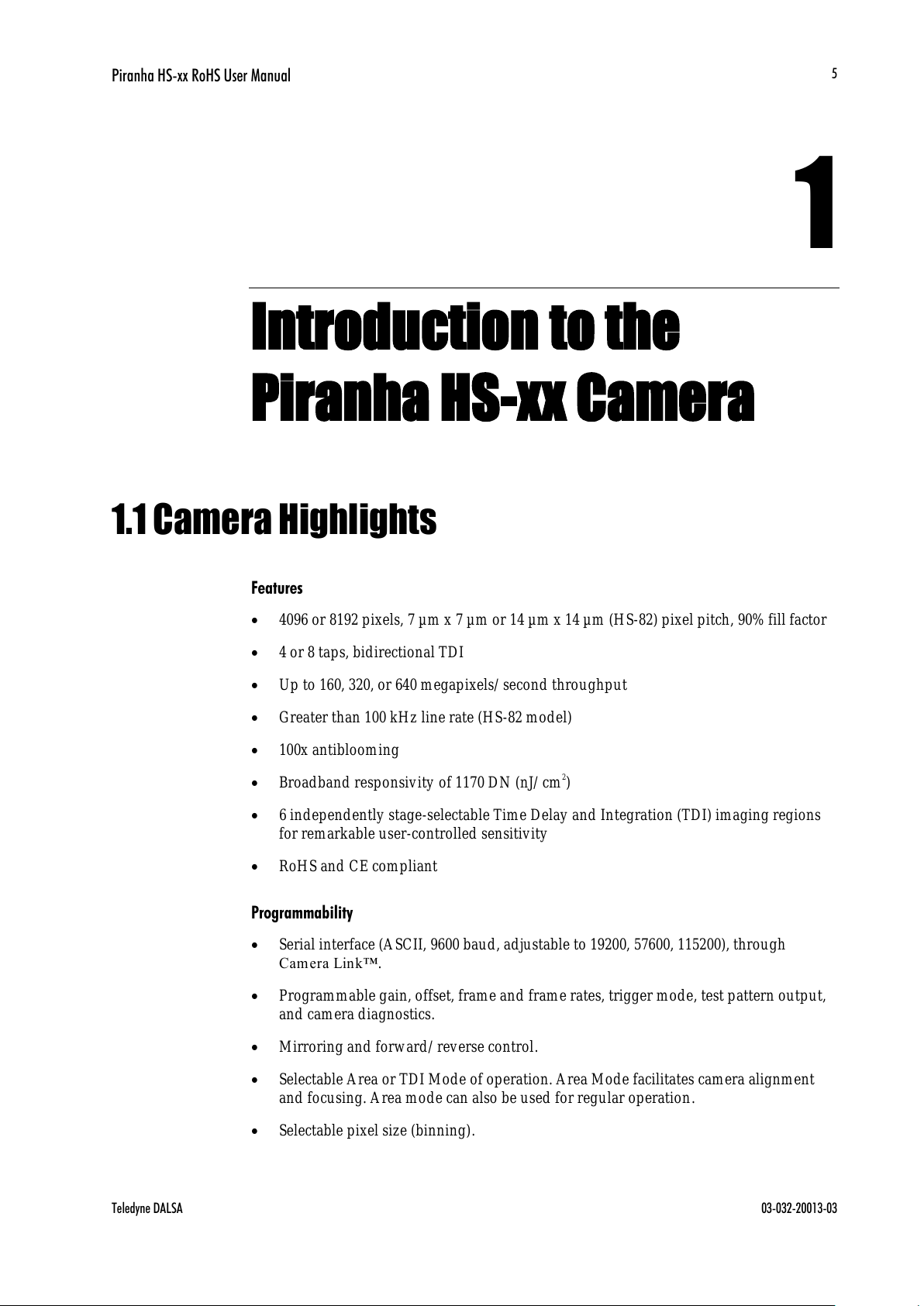
1.1 Camera Highlights
Features
4096 or 8192 pixels, 7 µm x 7 µm or 14 µm x 14 µm (HS-82) pixel pitch, 90% fill factor
4 or 8 taps, bidirectional TDI
Up to 160, 320, or 640 megapixels/ second throughput
Greater than 100 kHz line rate (HS-82 model)
100x antiblooming
Broadband responsivity of 1170 DN (nJ/ cm2)
6 independently stage-selectable Time Delay and Integration (TDI) imaging regions
for remarkable user-controlled sensitivity
RoHS and CE compliant
Programmability
Serial interface (ASCII, 9600 baud, adjustable to 19200, 57600, 115200), through
Camera Lin k™.
Programmable gain, offset, frame and frame rates, trigger mode, test pattern output,
and camera diagnostics.
Mirroring and forward/ reverse control.
Selectable Area or TDI Mode of operation. Area Mode facilitates camera alignment
and focusing. Area mode can also be used for regular operation.
Selectable pixel size (binning).
All manuals and user guides at all-guides.com
Piranha HS-xx RoHS User Manual
03-032-20013-03 Teledyne DALSA
6
Flat-field correction—minimizes lens vignetting, non-uniform lighting, and sensor
FPN and PRNU.
Selectable Base, Medium, or Full Camera Link configuration, depending on camera
model.
Description
The Piranha HS camera family represent Teledyne DALSA's latest generation of high
sensitivity, TDI based cameras. The Piranha HS family maximizes system throughput and
provides the largest number of pixels available in a TDI camera. All cameras are capable
of bi-directionality with up to 96 stages of integration.
Applications
The Piranha HS family is ideal for applications requiring high speed, superior image
quality, and high responsivity. These applications include:
Postal sorting (flats)
Flat panel display inspection
Printed circuit board inspection
High performance document scanning
Large web inspection
Low-light applications
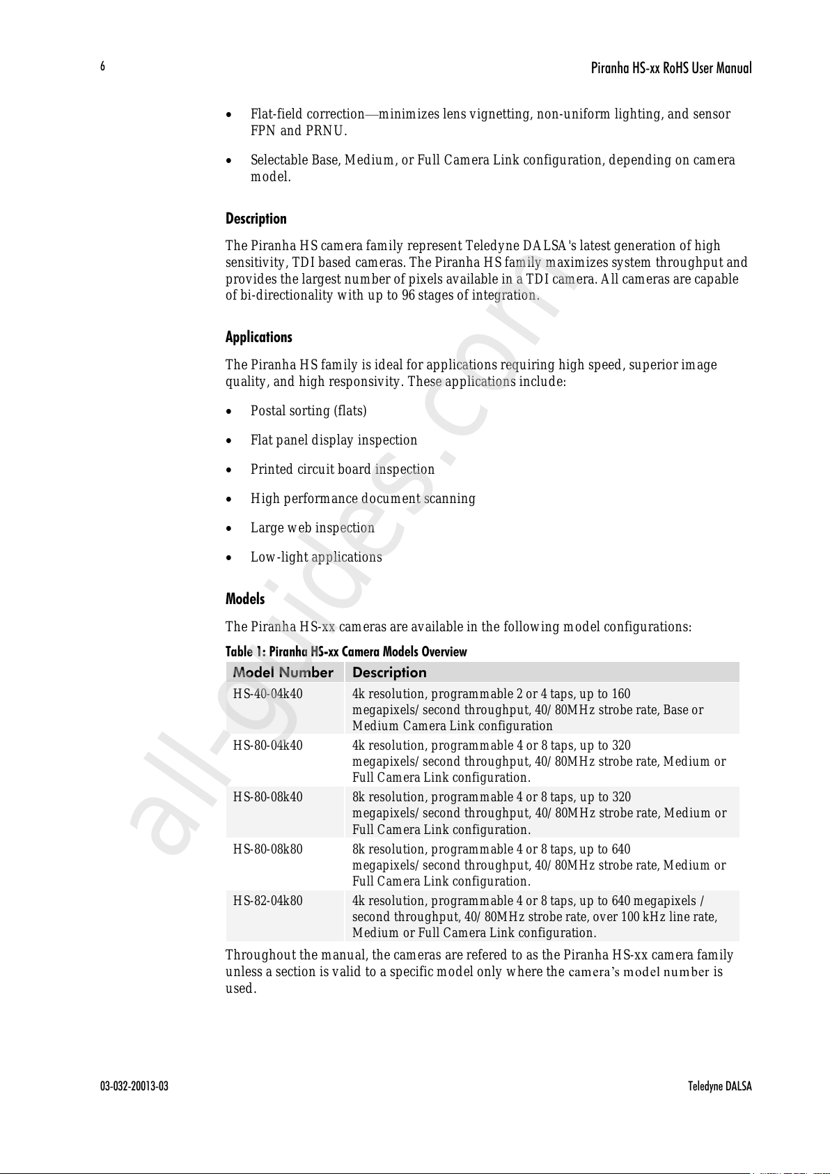
Models
The Piranha HS-xx cameras are available in the following model configurations:
Table 1: Piranha HS-xx Camera Models Overview
Model Number
Description
HS-40-04k40
4k resolution, programmable 2 or 4 taps, up to 160
megapixels/ second throughput, 40/ 80MHz strobe rate, Base or
Medium Camera Link configuration
HS-80-04k40
4k resolution, programmable 4 or 8 taps, up to 320
megapixels/ second throughput, 40/ 80MHz strobe rate, Medium or
Full Camera Link configuration.
HS-80-08k40
8k resolution, programmable 4 or 8 taps, up to 320
megapixels/ second throughput, 40/ 80MHz strobe rate, Medium or
Full Camera Link configuration.
HS-80-08k80
8k resolution, programmable 4 or 8 taps, up to 640
megapixels/ second throughput, 40/ 80MHz strobe rate, Medium or
Full Camera Link configuration.
HS-82-04k80
4k resolution, programmable 4 or 8 taps, up to 640 megapixels /
second throughput, 40/ 80MHz strobe rate, over 100 kHz line rate,
Medium or Full Camera Link configuration.
Throughout the manual, the cameras are refered to as the Piranha HS-xx camera family
unless a section is valid to a specific model only where the ca m era’s m odel n u m ber is
used.
All manuals and user guides at all-guides.com
all-guides.com

Piranha HS-xx RoHS User Manual
Teledyne DALSA 03-032-20013-03
7
1.2 Camera Performance Specifications
Features and Specifications
Model
HS-40-04k40
HS-80-04k-40
HS-80-08k40
HS-80-08k80
HS-82-04k80
Imager Format
Bidirectional TDI —all models
Resolution
4096 pixels
4096
8196
8196
4096 x 48
Pixel Fill Factor
90 %
100 %
90 %
100 %
100 %
Pixel Size
7x7 µm
7x7 µm
7x7 µm
7x7 µm
14 x 14 µm
Output Format (# of
Camera Link taps)
2 or 4
4 or 8
4 or 8
4 or 8
4 or 8
Stage Selection
16, 32, 48, 64, 80, 96 — all models
Antiblooming
100 x — all models
CCD Shift Direction
Change
0.2 seconds— all models
Optical Interface
Model
HS-40-04k40
HS-80-04k-40
HS-80-08k40
HS-80-08k80
HS-82-04k80
Back Focal Distance
F Mount
M42x1 Mount
M72 Mount
46.50 ± 0.18 mm
6.56 ± 0.25 mm
—
—
6.56 ± 0.25
—
—
6.56 ± 0.25
—
—
6.56 ± 0.25
—
—
6.56 ± 0.25
Sensor Alignment
(aligned to sides of
camera)
± 0.05 mm x
± 0.05 mm y
± 0.25 mm z
± 0.2 ° z
Lens Mount Hole1
62 mm hole. M42 or
F mount adapter
available.
M72 x 0.75
M72 x 0.75
M72 x 0.75
M72 x 0.75
Mechanical Interface
Model
HS-40-04k40
HS-80-04k-40
HS-80-08k40
HS-80-08k80
HS-82-04k80
Camera Size
85 (l) x 85 (h) x 55.4
(w) mm
80 (l) x 150 (h) x
65 (w)
80 (l) x 150
(h) x 65 (w)
80 (l) x 150 (h) x
65 (w)
80 (l) x 150 (h) x
65 (w)
Mass
< 500 g
< 800 g
< 800 g
< 800 g
< 800 g
Connectors
6 pin male Hirose, power
MDR26 female, data
Electrical Interface
Model
HS-40-04k40
HS-80-04k40
HS-80-08k40
HS-80-08k80
HS-82-04k80
Input Voltage
+ 12 to + 15 ± 5 % Volts DC — all models
Power Dissipation2
10 W
19 W
14.4 W
19 W
< 20 W
Operating
Temperature3
0 to 50 °C — all models
Bit Width
8 or 12 bit user selectable bits — all models
Output Data
Configuration
Base or Medium
Camera Link
Medium or Full
Camera Link
Medium or
Full Camera
Link
Medium or Full
Camera Link
Medium or
Full Camera
Link
All manuals and user guides at all-guides.com
Piranha HS-xx RoHS User Manual
03-032-20013-03 Teledyne DALSA
8
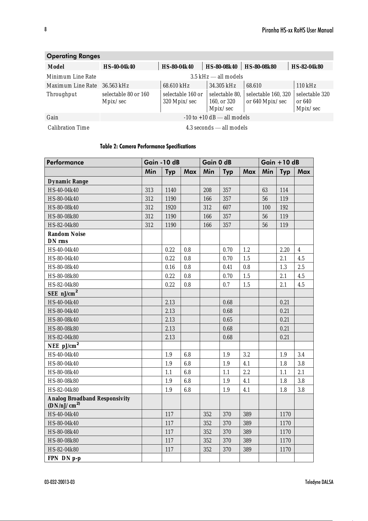
Operating Ranges
Model
HS-40-04k40
HS-80-04k40
HS-80-08k40
HS-80-08k80
HS-82-04k80
Minimum Line Rate
3.5 kHz — all models
Maximum Line Rate
36.563 kHz
68.610 kHz
34.305 kHz
68.610
110 kHz
Throughput
selectable 80 or 160
Mpix/ sec
selectable 160 or
320 Mpix/ sec
selectable 80,
160, or 320
Mpix/ sec
selectable 160, 320
or 640 Mpix/ sec
selectable 320
or 640
Mpix/ sec
Gain
-10 to +10 dB — all models
Calibration Time
4.3 seconds — all models
Table 2: Camera Performance Specifications
Performance
Gain -10 dB
Gain 0 dB
Gain +10 dB
Min
Typ
Max
Min
Typ
Max
Min
Typ
Max
Dynamic Range
HS-40-04k40
313
1140
208
357 63
114 HS-80-04k40
312
1190
166
357 56
119 HS-80-08k40
312
1920
312
607 100
192 HS-80-08k80
312
1190
166
357 56
119 HS-82-04k80
312
1190
166
357 56
119
Random Noise
DN rms
HS-40-04k40
0.22
0.8 0.70
1.2 2.20 4 HS-80-04k40
0.22
0.8 0.70
1.5 2.1
4.5
HS-80-08k40
0.16
0.8 0.41
0.8 1.3
2.5
HS-80-08k80
0.22
0.8 0.70
1.5 2.1
4.5
HS-82-04k80
0.22
0.8 0.7
1.5 2.1
4.5
SEE nJ/cm2
HS-40-04k40
2.13
0.68
0.21 HS-80-04k40
2.13
0.68
0.21 HS-80-08k40
2.13
0.65
0.21 HS-80-08k80
2.13
0.68
0.21 HS-82-04k80
2.13
0.68
0.21
NEE pJ/cm2
HS-40-04k40
1.9
6.8 1.9
3.2 1.9
3.4
HS-80-04k40
1.9
6.8 1.9
4.1 1.8
3.8
HS-80-08k40
1.1
6.8 1.1
2.2 1.1
2.1
HS-80-08k80
1.9
6.8 1.9
4.1 1.8
3.8
HS-82-04k80
1.9
6.8 1.9
4.1 1.8
3.8
Analog Broadband Responsivity
(DN/nJ/ cm2)
HS-40-04k40
117 352
370
389 1170
HS-80-04k40
117 352
370
389 1170
HS-80-08k40
117 352
370
389 1170
HS-80-08k80
117 352
370
389 1170
HS-82-04k80
117 352
370
389 1170
FPN DN p-p
All manuals and user guides at all-guides.com

Piranha HS-xx RoHS User Manual
Teledyne DALSA 03-032-20013-03
9
Performance
Gain -10 dB
Gain 0 dB
Gain +10 dB
with correction
HS-40-04k40
0.5 2
HS-80-04k40
0.5 2
HS-80-08k40
0.5 2
HS-80-08k80
0.5 2
HS-82-04k80
0.5 2
FPN DN p-p
w/o correction
HS-40-04k40
1 3 2 6
10
18
HS-80-04k40
3 4.5 3 9
HS-80-08k40
3 3 3 9
HS-80-08k80
3 4.5 3 9
HS-82-04k80
3 4.5 3 9
PRNU DN p-p
with correction
HS-40-04k40
3
5.5 HS-80-04k40
4.0 8
HS-80-08k40
3.2
5.5 HS-80-08k80
4.0 8
HS-82-04k80
4.0 8
PRNU %
w/o correction
HS-40-04k40
4 10 5
12 10
25
HS-80-04k40
22
22 10
25
HS-80-08k40
22
22 7
25
HS-80-08k80
22
22 10
25
HS-82-04k80
22
22 10
25
Saturation Output Amplitude
DN
255 typ
DC Offset
DN
3 min
5 typ
6 max
Test conditions for all models, unless otherwise noted:
TDI mode of operation. These specifications are not guaranteed for area mode of
operation.
Line Rate: 10 kHz.
Nominal Gain setting.
Light Source: Broadband Quartz Halogen, 3250 k, with 700 nm IR cutoff filter
installed.
All Max specifications are valid over a 0-50 °C temperature range.
All Typ specifications are measured at 25 °C.
All values are referenced at 8-bit.
1. Maximum using highest Camera Link mode and maximum line rate.
All manuals and user guides at all-guides.com
Piranha HS-xx RoHS User Manual
03-032-20013-03 Teledyne DALSA
10
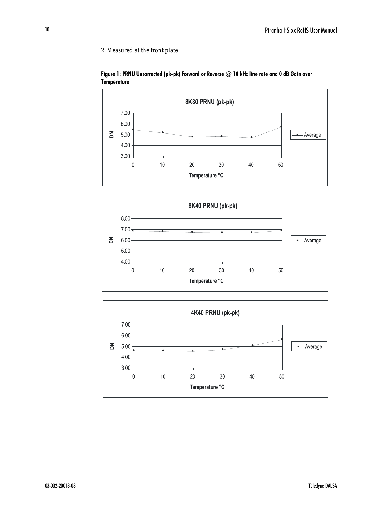
2. Measured at the front plate.
Figure 1: PRNU Uncorrected (pk-pk) Forward or Reverse @ 10 kHz line rate and 0 dB Gain over
Temperature
All manuals and user guides at all-guides.com

Piranha HS-xx RoHS User Manual
Teledyne DALSA 03-032-20013-03
11
Figure 2: FPN Forward or Reverse @ 10 kHz line rate and 0 dB Gain over Temperature
All manuals and user guides at all-guides.com
all-guides.com

Piranha HS-xx RoHS User Manual
03-032-20013-03 Teledyne DALSA
12
Figure 3: Random Noise Forward or Reverse @ 10 kHz line rate and 0 dB Gain over Temperature
All manuals and user guides at all-guides.com

Piranha HS-xx RoHS User Manual
Teledyne DALSA 03-032-20013-03
13
Figure 4: DC Offset Forward or Reverse @ 10 kHz line rate and 0 dB Gain over Temperature
All manuals and user guides at all-guides.com

Piranha HS-xx RoHS User Manual
03-032-20013-03 Teledyne DALSA
14
1.3 Image Sensor
The camera uses Teledyne DALSA’s newest bidirectional TDI sensors. The camera can be
configured to read out in either Forward or Reverse CCD shift direction. Readout
direction is controlled by the software command scd.
Figure 5: 4 Tap Sensor Block Diagram (HS-40-04k40)
1R
2R
3R
4R
2F 3F
4F
1F
Forward CCD Readout Shift Register
Reverse CCD Readout Shift Register
T
D
I
C
o
l
u
m
n
4
0
9
5
TDI Column 1
6 Isolation Rows
6 Isolation Rows1/4
TDI Imaging Region
7µm x 7µm pixels
96 TDI Rows
TDI Column 4 096
TDI C olumn 2
16 STG
32 STG
48 STG
64 STG
80 STG
96 STG
Figure 6: 16 Tap Sensor Block Diagram (HS-80-04k40, HS-80-08k80)
16 STG
32 STG
48 STG
64 STG
80 STG
96 STG
2F
3F 4F 5F 6F 7F 9F1F
Forward CCD Readout Shift Register
Reverse CCD Readout Shift Register
T
D
I
C
o
l
u
m
n
8
1
9
1
TDI C olumn 8 192
TDI C olumn 1
TDI Col umn 2
6 Isolation Rows
6 Isolation Rows1/4
TDI Imaging Region
7µm x 7µm pixels
96 TDI Rows
8F 10F
11F
12F
13F 14F15F16F
2R 3R 4R 6R
7R9R8R 10R
11R12R
13R14R
15R16R
1R
T1
T2
T3 T4
T5 T6
T7
T8
T1 T2
T3
T4
T5
T6 T7 T8
5R
Camera Link Tap
Camera Link Tap
CCD Tap
CCD Tap
All manuals and user guides at all-guides.com

Piranha HS-xx RoHS User Manual
Teledyne DALSA 03-032-20013-03
15
1.4 Responsivity
Figure 7: Piranha HS Analog Responsivity
All manuals and user guides at all-guides.com

Piranha HS-xx RoHS User Manual
03-032-20013-03 Teledyne DALSA
16
All manuals and user guides at all-guides.com
all-guides.com
Piranha HS-xx RoHS User Manual
Teledyne DALSA 03-032-20013-03
17
2
Camera Hardware
Interface
2.1 Installation Overview
When installing your camera, you should take these steps:
1. Power down all equipment.
2. Follow the m anu factu rer’s instructions to install the framegrabber (if applicable). Be
sure to observe all static precautions.
3. Install any necessary imaging software.
4. Before connecting power to the camera, test all power supplies. Ensure that all the
correct voltages are present at the camera end of the power cable. Power supplies
must meet the requirements defined in section 2.2.2 Power Connector.
5. Inspect all cables and connectors prior to installation. Do not use damaged cables or
connectors or the camera may be damaged.
6. Connect Camera Link and power cables.
7. After connecting cables, apply power to the camera.
8. Check the diagnostic LED. See 2.2.1 LED Status Indicator for an LED description.
You must also set up the other components of you r system, including light sources,
camera mounts, host computers, optics, encoders, and so on.
2.2 Input/Output Connectors and LED
The camera uses:
A diagnostic LED for monitoring the camera. See LED Status Indicator in section 2.2.1
LED Status Indicator for details.
This installation
overview assumes you
have not installed any
system components yet.
All manuals and user guides at all-guides.com

Piranha HS-xx RoHS User Manual
03-032-20013-03 Teledyne DALSA
18
!
High-density 26-pin MDR26 connectors for Camera Link control signals, data signals,
and serial communications. Refer to section 2.2.3 Camera Link Data Connector for
details.
One 6-pin Hirose connector for power. Refer to section 2.2.2 Power Connector for
details.
Figure 8: Piranha HS-xx Input and Output Connectors (4k Models)
Figure 9: Piranha HS-xx Input and Output Connectors (8k Models)
WARNING: It is extremely important that you apply the appropriate voltages to your camera.
Incorrect voltages will damage the camera. See 2.2.2 Power Connector for more details.
Camera Link (Base Configuration)
Camera Link (Medium Configuration)
Diagnostic LED
+12VDC to +15 VDC and Ground
Camera Link (Medium or Full Configuration)
Camera Link (Medium or Full Configuration)
Diagnostic LED
+12VDC to +15VDC and Ground
All manuals and user guides at all-guides.com

Piranha HS-xx RoHS User Manual
Teledyne DALSA 03-032-20013-03
19
!
2.2.1 LED Status Indicator
The camera is equipped with a red/ green LED used to display the operational status of
the camera. The table below summarizes the operating states of the camera and the
corresponding LED states.
When more than one condition is active, the LED indicates the condition with the highest
priority. Error and warning states are accompanied by corresponding messages further
describing the current camera status.
Table 3: Diagnostic LED
Priority
Color of Status LED
Meaning
1
Flashing Red
Fatal Error. Camera temperature is too high and
camera thermal shutdown has occurred or a power
on failure has been detected.
2
Solid Red
Warning. Loss of functionality.
3
Flashing Green
Camera initialization or executing a long command
(e.g., flat field correction commands ccp or ccf)
4
Solid Green
Camera is operational and functioning correctly.
2.2.2 Power Connector
Figure 10: Hirose 6-pin Circular Male—Power Connector
Hirose 6-pin Circular Male
5
4
6
2
3
1
Mating Part: HIROSE
HR10A-7P-6S
The camera requires a single voltage input (+12 to +15VDC). The camera meets all
performance specifications using standard switching power supplies, although well-
regulated linear supplies provide optimum performance.
WARNING: When setting up the camera’s power supplies follow these guidelines:
Apply the appropriate voltages
Protect the camera with a fast-blow fuse between power supply and camera.
Do not use the shield on a multi-conductor cable for ground.
Keep leads as short as possible to reduce voltage drop.
Use high-quality linear supplies to minimize noise.
Use an isolated type power supply to prevent LVDS common mode range violation.
Note: Camera performance specifications are not guaranteed if your power supply does not
meet these requirements.
Table 4: Hirose Pin Description
Pin
Description
Pin
Description
1
Min +12 to Max +15VDC
4
GND
2
Min +12 to Max +15VDC
5
GND
3
Min +12 to Max +15VDC
6
GND
All manuals and user guides at all-guides.com
Piranha HS-xx RoHS User Manual
03-032-20013-03 Teledyne DALSA
20
Teledyne DALSA offers a power supply w ith attached 6’ power cable that m eets th e
Pir anh a HS camera’s requirements, bu t it should not be consid ered th e only ch oice. Many
high quality supplies are available from other vendors.
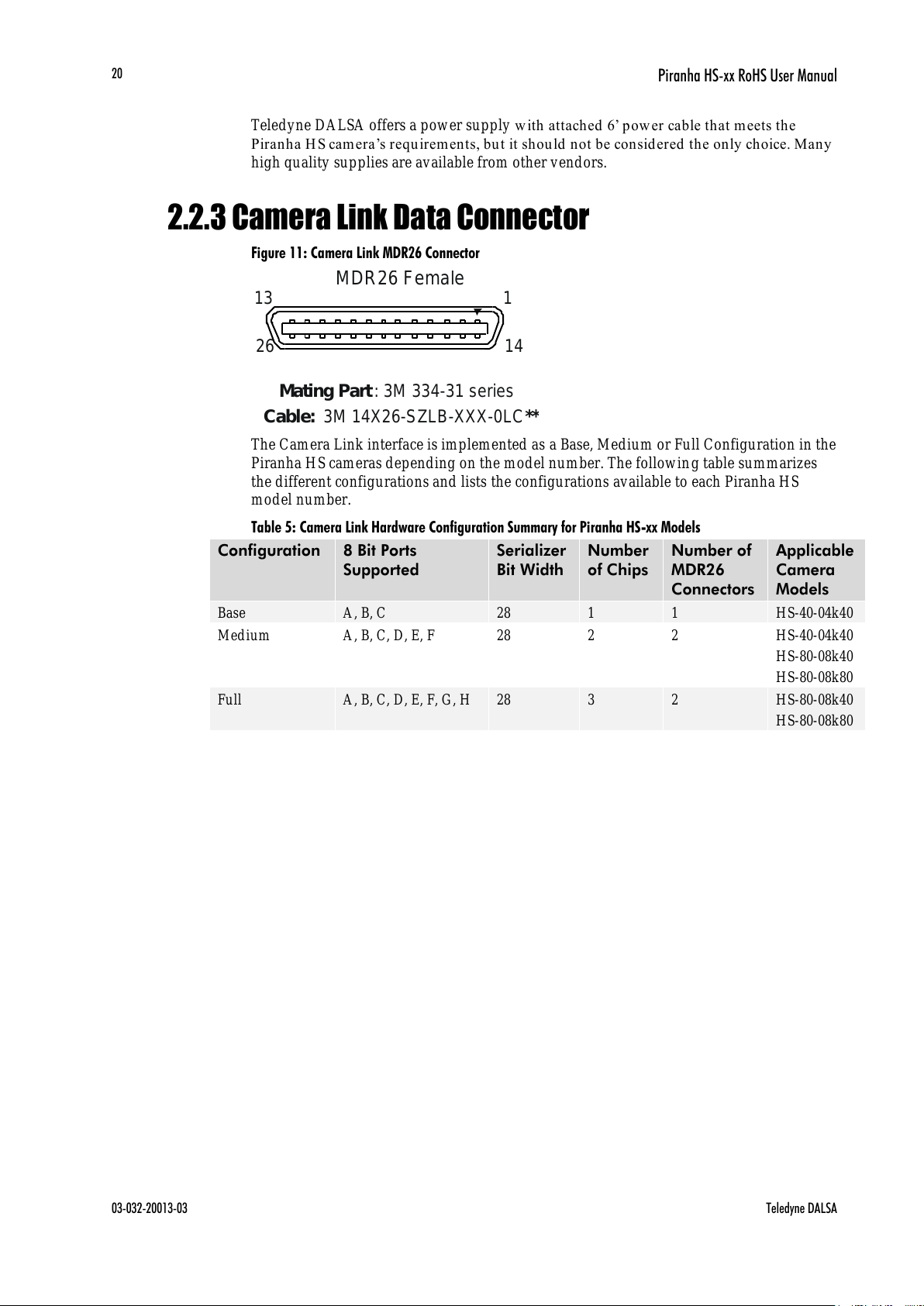
2.2.3 Camera Link Data Connector
Figure 11: Camera Link MDR26 Connector
MDR26 Female
1
14
13
26
Mating Part: 3M 334-31 series
Cable: 3M 14X26-SZLB-XXX-0LC**
The Camera Link interface is implemented as a Base, Medium or Full Configuration in the
Piranha HS cameras depending on the model number. The following table summarizes
the different configurations and lists the configurations available to each Piranha HS
model number.
Table 5: Camera Link Hardware Configuration Summary for Piranha HS-xx Models
Configuration
8 Bit Ports
Supported
Serializer
Bit Width
Number
of Chips
Number of
MDR26
Connectors
Applicable
Camera
Models
Base
A, B, C
28 1 1
HS-40-04k40
Medium
A, B, C, D, E, F
28 2 2
HS-40-04k40
HS-80-08k40
HS-80-08k80
Full
A, B, C, D, E, F, G, H
28 3 2
HS-80-08k40
HS-80-08k80
All manuals and user guides at all-guides.com

Piranha HS-xx RoHS User Manual
Teledyne DALSA 03-032-20013-03
21
Table 6: Camera Link Connector Pinout
Medium and Full Configurations
Base Configuration
Up to an additional 2 Channel Link Chips
One Channel Link Chip + Camera
Control + Serial Communication
Camera
Connector
Right Angle
Frame
Grabber
Channel
Link Signal
Cable
Name
Camera
Connector
Right Angle
Frame
Grabber
Channel
Link Signal
1 1 inner shield
Inner Shield
1 1
inner shield
14
14
inner shield
Inner Shield
14
14
inner shield
2
25
Y0-
PAIR1-
2 25
X0-
15
12
Y0+
PAIR1+
15
12
X0+ 3 24
Y1-
PAIR2-
3 24
X1-
16
11
Y1+
PAIR2+
16
11
X1+ 4 23
Y2-
PAIR3-
4 23
X2-
17
10
Y2+
PAIR3+
17
10
X2+ 5 22
Yclk-
PAIR4-
5 22
Xclk-
18 9 Yclk+
PAIR4+
18 9 Xclk+
6
21
Y3-
PAIR5-
6 21
X3-
19 8 Y3+
PAIR5+
19 8 X3+ 7 20
100 ohm
PAIR6+
7 20
SerTC+
20 7 terminated
PAIR6-
20 7 SerTC-
8
19
Z0-
PAIR7-
8 19
SerTFG-
21 6 Z0+
PAIR7+
21 6 SerTFG+
9
18
Z1-
PAIR8-
9 18
CC1-
22 5 Z1+
PAIR8+
22 5 CC1+
10
17
Z2-
PAIR9+
10
17
CC2+
23 4 Z2+
PAIR9-
23 4 CC2-
11
16
Zclk-
PAIR10-
11
16
CC3-
24 3 Zclk+
PAIR10+
24 3 CC3+
12
15
Z3-
PAIR11+
12
15
CC4+
25 2 Z3+
PAIR11-
25 2 CC4-
13
13
inner shield
Inner Shield
13
13
inner shield
26
26
inner shield
Inner Shield
26
26
inner shield
Notes:
*Exterior Overshield is connected to the shells of the connectors on both ends.
**3M part 14X26-SZLB-XXX-0LC is a complete cable assembly, including connectors.
Unused pairs should be terminated in 100 ohms at both ends of the cable.
Inner shield is connected to signal ground inside camera
Table 7: Teledyne DALSA Camera Control Configuration
Signal
Configuration
CC1
EXSYNC
CC2
Spare
CC3
Forward
CC4
Spare
All manuals and user guides at all-guides.com
all-guides.com

Piranha HS-xx RoHS User Manual
03-032-20013-03 Teledyne DALSA
22
See Appendix B for the complete Teledyne DALSA Camera Link configuration table, and
refer to the Teledyne DALSA Web site, Knowledge Center application notes, for the
official Camera Link documents.
Input Signals, Camera Link
The camera accepts control inputs through the Camera Link MDR26F connector.
The camera ships in internal sync, internal programmed integration (exposure mode 7) TDI Mode.
EXSYNC (Triggers Frame Readout)
Frame rate can be set internally using the serial interface. The external control signal
EXSYNC is optional and enabled through the serial interface. This camera uses the falling
edge of EXSYNC to trigger pixel readout. Section Exposure Mode and Line/ Frame Rate
for details on how to set frame times, exposure times, and camera modes.
Direction Control
You control the CCD shift direction through the serial interface. With the software
command, scd, you determine whether the direction control is set via software control or
via the Camera Link control signal on CC3. Refer to section Settin g the Cam er a’s CCD
Shift Direction for details.
Output Signals, Camera Link
These signals indicate when data is valid, allowing you to clock the data from the camera
to your acquisition system. These signals are part of the Camera Link configuration and
you should refer to the Teledyne DALSA Camera Link Implementation Road Map,
available at Knowledge Center, for the standard location of these signals.
Clocking Signal
Indicates
LVAL (high)
Outputting valid line
DVAL (high)
Valid data
STROBE (rising edge)
Valid data
FVAL (high)
Outputting valid frame
The camera internally digitizes 12 bits and outputs 8 MSB or all 12 bits depending on
th e ca m era’s Cam er a Link op eratin g mod e. Refer to 4.4.2 Setting the Camera Link
Mode for details.
For a Camera Link reference refer to Appendix A on page 119.
2.3 Camera Link Video Timing
The Piranha HS-xx camera has two different readout times. The first readout time is the
CCD Read ou t w h ere the camera p ixels are read ou t into th e cam era’s lin estore. The
second readout is the linestore readout where the linestore pixels are read ou t to your
acquisition system . Th e cam era’s m in im u m readou t tim e is d ependan t on which of these
tw o read out tim es are greater w here th e greater read out tim e w ill be the cam era’s
minimum readout time.
IMPORTANT:
This camera’s data
should be sampled on
the rising edge of
STROBE.
i
All manuals and user guides at all-guides.com
Piranha HS-xx RoHS User Manual
Teledyne DALSA 03-032-20013-03
23
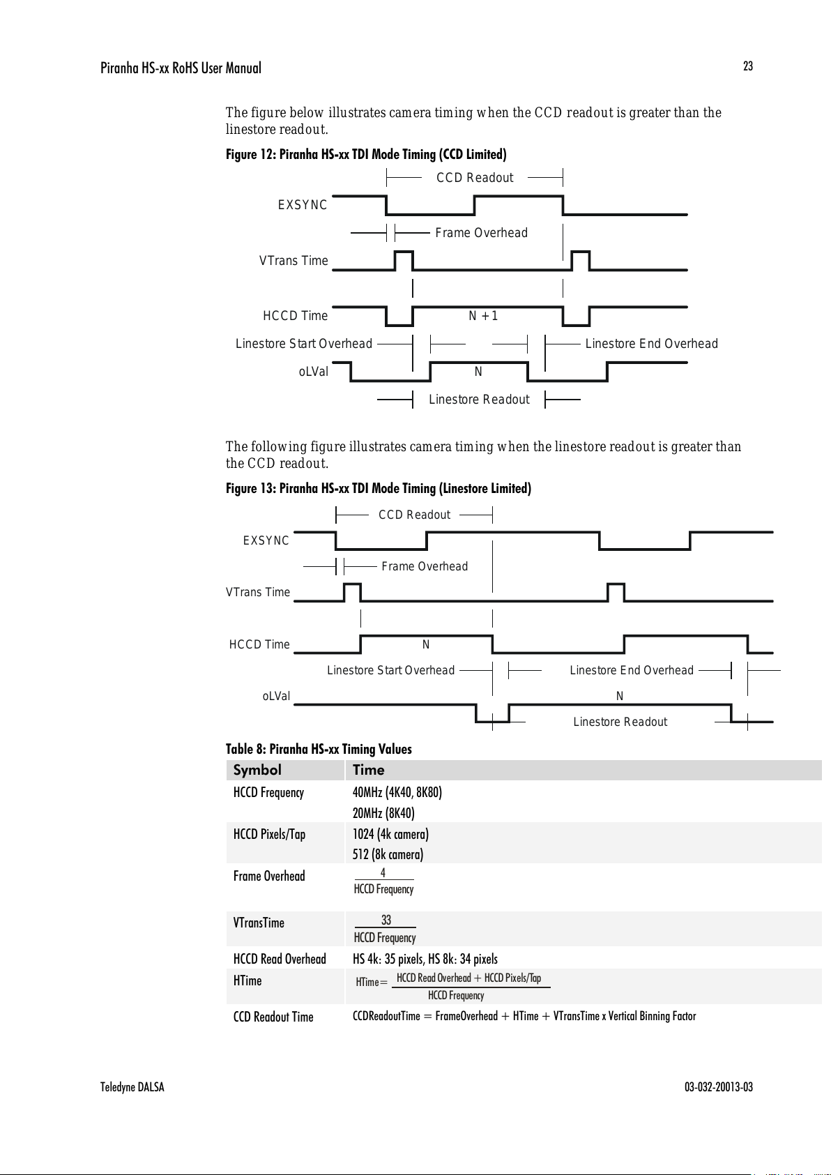
The figure below illustrates camera timing when the CCD readout is greater than the
linestore readout.
Figure 12: Piranha HS-xx TDI Mode Timing (CCD Limited)
CCD Readout
EXSYNC
Frame Overhead
VTrans Time
HCCD Time
Linestore Start Overhead Linestore End Overhead
oLVal
Linestore Readout
N + 1
N
The following figure illustrates camera timing when the linestore readout is greater than
the CCD readout.
Figure 13: Piranha HS-xx TDI Mode Timing (Linestore Limited)
CCD Readout
EXSYNC
Frame Overhead
VTrans Time
HCCD Time
Linestore Start Overhead Linestore End Overhead
oLVal
Linestore Readout
N
N
Table 8: Piranha HS-xx Timing Values
Symbol
Time
HCCD Frequency
40MHz (4K40, 8K80)
20MHz (8K40)
HCCD Pixels/Tap
1024 (4k camera)
512 (8k camera)
Frame Overhead
4
HCCD Frequency
VTransTime
33
HCCD Frequency
HCCD Read Overhead
HS 4k: 35 pixels, HS 8k: 34 pixels
HTime
HTime=
HCCD Read Overhead + HCCD Pixels/Tap
HCCD Frequency
CCD Readout Time
CCDReadoutTime = FrameOverhead + HTime + VTransTime x Vertical Binning Factor
All manuals and user guides at all-guides.com

Piranha HS-xx RoHS User Manual
03-032-20013-03 Teledyne DALSA
24
Symbol
Time
HCCD Taps
4 (4K40)
16 (8Kxx)
Linestore Start
Overhead
15 clocks
Linestore End Overhead
23 clocks
Linestore Readout Time
HCCD Pixels/Tap x HCCD Taps
# Camera Link Taps x Horizontal Binning Factor
+Linestore Start Overhead +Linestore End Overhead
# Camera Link Taps
Throughput (MHz)
x
Horizontal Binning
Factor
Value set with sbh command
Vertical Binning Factor
Value set with sbv command
Vertical Readout Rows
Stage selection set with stg command
# of Camera Link Taps
Value set with the clm command
Throughput
Value set with sot command
Figure 14: Piranha HS-xs Area Mode Timing (CCD Limited)
Figure 15: Piranha HS-xx Area Mode Timing (Linestore Limited)
Table 9: Piranha Input and Output
Symbol
Time
CCD Readout Time
(Area Mode)
EXSYNC
User LVAL
User FVAL
Internal HTime
EXSYNC
User LVAL
User FVAL
CCD ReadoutTime=
Frame Overhead
+
HTime
Vertical readout rows + ISORows
Vertical Binning Factor
+
x
VTransTime
HCCD Frequency
Remainder
+
HTime
Vertical readout rows + ISORows
Vertical Binning Factor
+
x
VTrans
Integer
x
Vertical Binning Factor
IMPORTANT:
This camera uses the
falling
edge of EXSYNC
to trigger line readout,
unlike previous DALSA
cameras, which used the
rising edge.
Internal HTime
All manuals and user guides at all-guides.com

Piranha HS-xx RoHS User Manual
Teledyne DALSA 03-032-20013-03
25
3
Optical and Mechanical
Considerations
3.1 Mechanical Interface
Figure 16: Piranha HS-xx Mechanical Dimensions
4k Resolution
All manuals and user guides at all-guides.com
Piranha HS-xx RoHS User Manual
03-032-20013-03 Teledyne DALSA
26
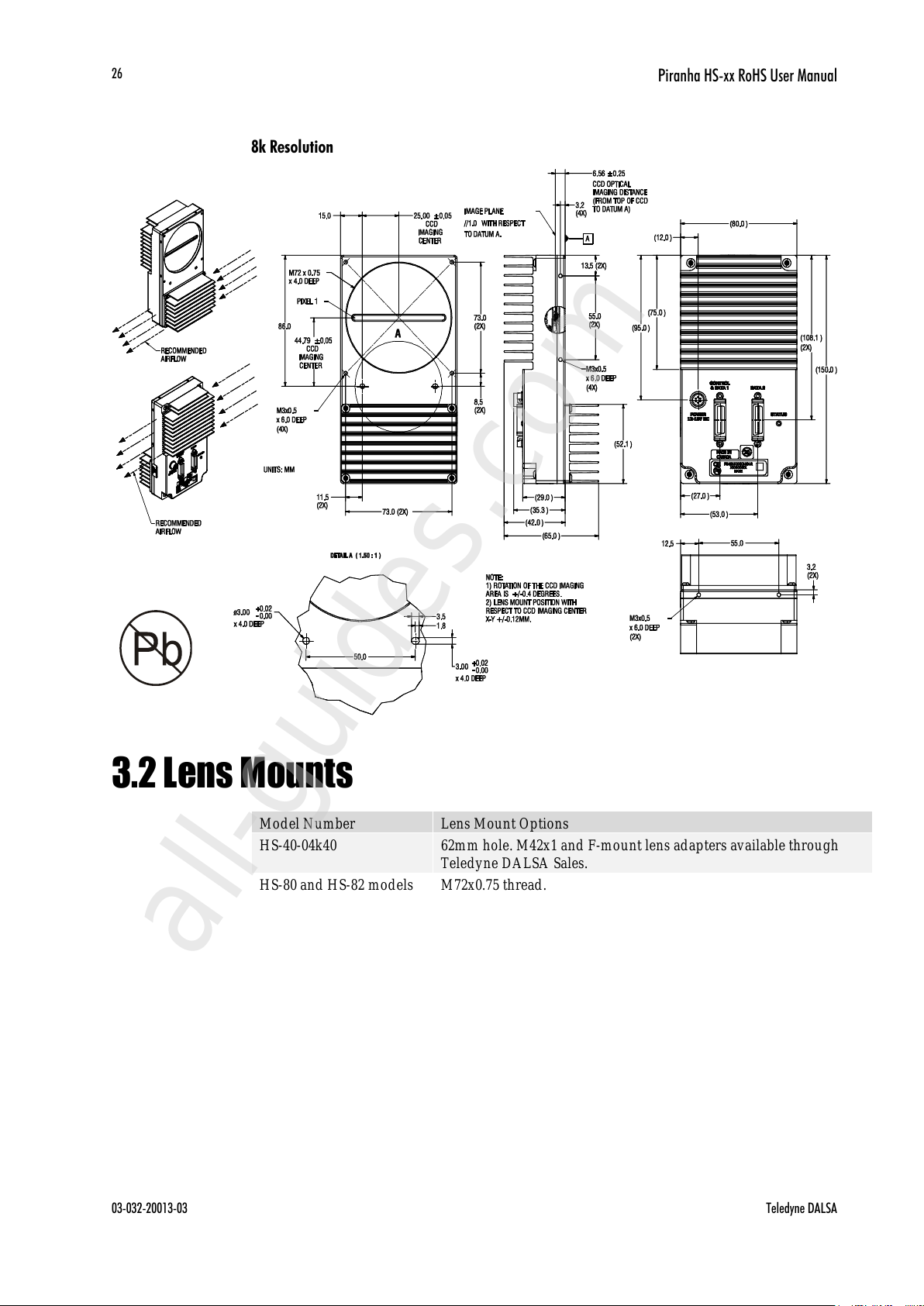
8k Resolution
3.2 Lens Mounts
Model Number
Lens Mount Options
HS-40-04k40
62mm hole. M42x1 and F-mount lens adapters available through
Teledyne DALSA Sales.
HS-80 and HS-82 models
M72x0.75 thread.
All manuals and user guides at all-guides.com
all-guides.com

Piranha HS-xx RoHS User Manual
Teledyne DALSA 03-032-20013-03
27
3.3 Optical Interface
Illumination
The amount and wavelengths of light required to capture useful images depend on the
particular application. Factors include the nature, speed, and spectral characteristics of
objects being imaged, exposure times, light source characteristics, environmental and
acquisition system specifics, and more.
It is often more important to consider exposure than illumination. The total amount of
energy (which is related to the total number of photons reaching the sensor) is more
important than the rate at which it arrives. For example, 5J/ cm2 can be achieved by
exposing 5mW/ cm2 for 1ms just the same as exposing an intensity of 5W/ cm2 for 1s.
Light Sources
Keep these guidelines in mind when setting up your light source:
LED light sources are relatively inexpensive, provide a uniform field, and longer life
span compared to other light sources. However, they also require a camera with
excellent sensitivity, such as the HS-xx camera.
Halogen light sources generally provide very little blue relative to infrared light (IR).
Fiber-optic light distribution systems generally transmit very little blue relative to IR.
Some light sources age; over their life span they produce less light. This aging may
not be uniform—a light source may produce progressively less light in some areas of
the spectrum but not others.
Filters
CCD cameras are extremely responsive to infrared (IR) wavelengths of light. To prevent
infrared from distortin g th e im a ges you sca n, use a ―h ot m irror ‖ or IR cutoff filter that
transmits visible wavelengths but does not transmit wavelengths over 750nm. Examples
are the Schn eider Op tics™ B+W 489, w h ich in clu d es a m ountin g rin g, th e CORIO N ™ LS-
750, which does not in clu d e a m ountin g rin g, an d the CORION ™ HR-750 series hot
mirror.
Lens Modeling
Any lens surrounded by air can be modeled for camera purposes using three primary
points: the first and second principal points and the second focal point. The primary
points for a lens should be available from the lens data sheet or from the lens
manufacturer. Primed quantities denote characteristics of the image side of the lens. That
is, h is the object height and h is the image height.
The focal point is the point at which the image of an infinitely distant object is brought to
focus. The effective focal length (f) is the distance from the second principal point to the
second focal point. The back focal length (BFL) is the distance from the image side of the
All manuals and user guides at all-guides.com

Piranha HS-xx RoHS User Manual
03-032-20013-03 Teledyne DALSA
28
lens surface to the second focal point. The object distance (OD) is the distance from the first
principal point to the object.
Figure 17: Primary Points in a Lens System
All manuals and user guides at all-guides.com
Piranha HS-xx RoHS User Manual
Teledyne DALSA 03-032-20013-03
29
4
Software Interface: How
to Control the Camera
All Piranha HS-xx camera features can be controlled through the serial interface. The
camera can also be used without the serial interface after it has been set up correctly.
Functions available include:
Controlling basic camera functions such as gain and sync signal source.
Flat field correction.
Mirroring and readout control.
Generating a test pattern for debugging.
The serial interface uses a simple ASCII-based protocol and the PC does not require any
custom software.
Note: This command set has changes from previous Teledyne DALSA cameras. Do not
assume that the Piranha HS commands perform similarly to older cameras.
Serial Protocol Defaults
8 data bits
1 stop bit
No parity
No flow control
9.6kbps
Camera does not echo characters
Command Format
i
This chapter outlines the
more commonly used
commands. See section
Commands for a list of all
available commands.
All manuals and user guides at all-guides.com
Piranha HS-xx RoHS User Manual
03-032-20013-03 Teledyne DALSA
30
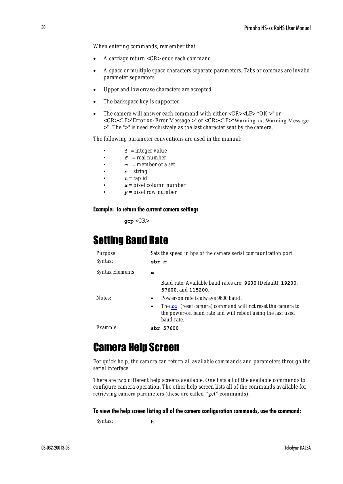
When entering commands, remember that:
A carriage return <CR> ends each command.
A space or multiple space characters separate parameters. Tabs or commas are invalid
parameter separators.
Upper and lowercase characters are accepted
The backspace key is supported
The camera will answer each command with either <CR><LF> ―OK >" or
<CR><LF>"Error xx: Error Message >" or <CR><LF>―Warn in g xx: Warn in g Message
>‖. The ">" is used exclusively as the last character sent by the camera.
The following parameter conventions are used in the manual:
• i = integer value
• f = real number
• m = member of a set
• s = string
• t = tap id
• x = pixel column number
• y = pixel row number
Example: to return the current camera settings
gcp <CR>
Setting Baud Rate
Purpose:
Sets the speed in bps of the camera serial communication port.
Syntax:
sbr m
Syntax Elements:
m
Baud rate. Available baud rates are: 9600 (Default), 19200,
57600, and 115200.
Notes:
Power-on rate is always 9600 baud.
The rc (reset camera) command will not reset the camera to
the power-on baud rate and will reboot using the last used
baud rate.
Example:
sbr 57600
Camera Help Screen
For quick help, the camera can return all available commands and parameters through the
serial interface.
There are two different help screens available. One lists all of the available commands to
configure camera operation. The other help screen lists all of the commands available for
retriev ing cam era p arameters (th ese are called ―get‖ command s).
To view the help screen listing all of the camera configuration commands, use the command:
Syntax:
h
All manuals and user guides at all-guides.com
Piranha HS-xx RoHS User Manual
Teledyne DALSA 03-032-20013-03
31
Command
Parameter Range
- = range
: = multiple parameter separator
/ = member of a set separator
NA = command not available in
current operating mode
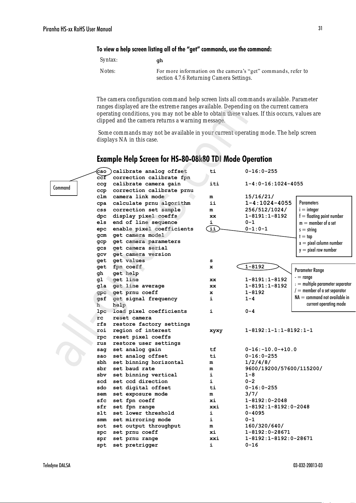
To view a help screen listing all of the ―get‖ commands, use the command:
Syntax:
gh
Notes:
For mor e in form ation on the camera’s ―get‖ com m and s, refer to
section 4.7.6 Returning Camera Settings.
The camera configuration command help screen lists all commands available. Parameter
ranges displayed are the extreme ranges available. Depending on the current camera
operating conditions, you may not be able to obtain these values. If this occurs, values are
clipped and the camera returns a warning message.
Some commands may not be available in your current operating mode. The help screen
displays NA in this case.
Example Help Screen for HS-80-08k80 TDI Mode Operation
cao calibrate analog offset ti 0-16:0-255
ccf correction calibrate fpn
ccg calibrate camera gain iti 1-4:0-16:1024-4055
ccp correction calibrate prnu
clm camera link mode m 15/16/21/
cpa calculate prnu algorithm ii 1-4:1024-4055
css correction set sample m 256/512/1024/
dpc display pixel coeffs xx 1-8191:1-8192
els end of line sequence i 0-1
epc enable pixel coefficients ii 0-1:0-1
gcm get camera model
gcp get camera parameters
gcs get camera serial
gcv get camera version
get get values s
get fpn coeff x 1-8192
gh get help
gl get line xx 1-8191:1-8192
gla get line average xx 1-8191:1-8192
gpc get prnu coeff x 1-8192
gsf get signal frequency i 1-4
h help
lpc load pixel coefficients i 0-4
rc reset camera
rfs restore factory settings
roi region of interest xyxy 1-8192:1-1:1-8192:1-1
rpc reset pixel coeffs
rus restore user settings
sag set analog gain tf 0-16:-10.0-+10.0
sao set analog offset ti 0-16:0-255
sbh set binning horizontal m 1/2/4/8/
sbr set baud rate m 9600/19200/57600/115200/
sbv set binning vertical i 1-8
scd set ccd direction i 0-2
sdo set digital offset ti 0-16:0-255
sem set exposure mode m 3/7/
sfc set fpn coeff xi 1-8192:0-2048
sfr set fpn range xxi 1-8192:1-8192:0-2048
slt set lower threshold i 0-4095
smm set mirroring mode i 0-1
sot set output throughput m 160/320/640/
spc set prnu coeff xi 1-8192:0-28671
spr set prnu range xxi 1-8192:1-8192:0-28671
spt set pretrigger i 0-16
Parameters
i = integer
f = floating point number
m = member of a set
s = string
t = tap
x = pixel column number
y = pixel row number
All manuals and user guides at all-guides.com
all-guides.com
Piranha HS-xx RoHS User Manual
03-032-20013-03 Teledyne DALSA
32
ssb set subtract background ti 0-16:0-4095
ssf set sync frequency f 3499.87-68610.6 [Hz]
ssg set system gain ti 0-16:0-65535
stg set stage m 16/32/48/64/80/96/
sut set upper threshold i 0-4095
svm set video mode i 0-2
tdi set area or TDI mode i 0-1
ugr update gain reference
vt verify temperature
vv verify voltage
wfc write FPN coefficients i 1-4
wpc write PRNU coefficients i 1-4
wus write user settings
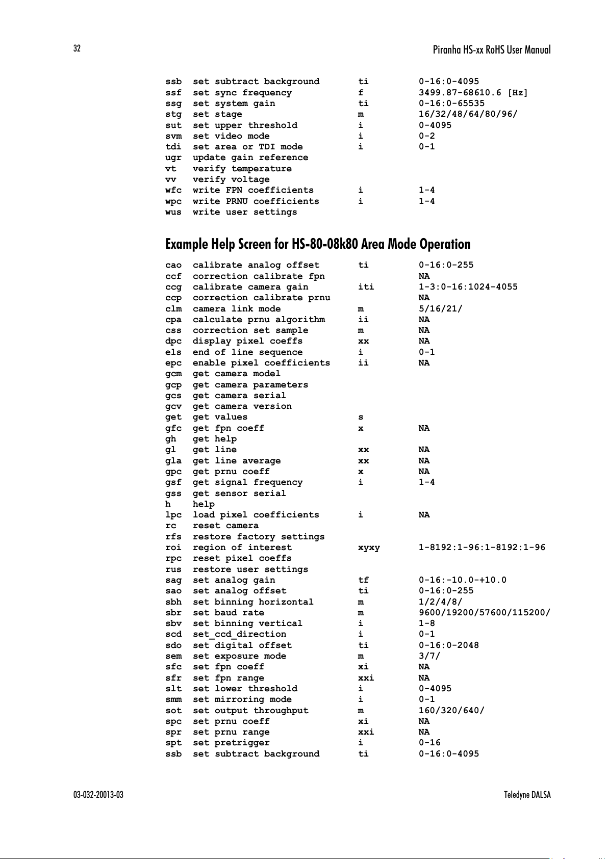
Example Help Screen for HS-80-08k80 Area Mode Operation
cao calibrate analog offset ti 0-16:0-255
ccf correction calibrate fpn NA
ccg calibrate camera gain iti 1-3:0-16:1024-4055
ccp correction calibrate prnu NA
clm camera link mode m 5/16/21/
cpa calculate prnu algorithm ii NA
css correction set sample m NA
dpc display pixel coeffs xx NA
els end of line sequence i 0-1
epc enable pixel coefficients ii NA
gcm get camera model
gcp get camera parameters
gcs get camera serial
gcv get camera version
get get values s
gfc get fpn coeff x NA
gh get help
gl get line xx NA
gla get line average xx NA
gpc get prnu coeff x NA
gsf get signal frequency i 1-4
gss get sensor serial
h help
lpc load pixel coefficients i NA
rc reset camera
rfs restore factory settings
roi region of interest xyxy 1-8192:1-96:1-8192:1-96
rpc reset pixel coeffs
rus restore user settings
sag set analog gain tf 0-16:-10.0-+10.0
sao set analog offset ti 0-16:0-255
sbh set binning horizontal m 1/2/4/8/
sbr set baud rate m 9600/19200/57600/115200/
sbv set binning vertical i 1-8
scd set_ccd_direction i 0-1
sdo set digital offset ti 0-16:0-2048
sem set exposure mode m 3/7/
sfc set fpn coeff xi NA
sfr set fpn range xxi NA
slt set lower threshold i 0-4095
smm set mirroring mode i 0-1
sot set output throughput m 160/320/640/
spc set prnu coeff xi NA
spr set prnu range xxi NA
spt set pretrigger i 0-16
ssb set subtract background ti 0-16:0-4095
All manuals and user guides at all-guides.com

Piranha HS-xx RoHS User Manual
Teledyne DALSA 03-032-20013-03
33
ssf set sync frequency f 1-6169.03 [Hz]
ssg set system gain ti 0-16:0-65535
stg set stage m 16/32/48/64/80/96/
sut set upper threshold i 0-4095
svm set video mode i 0-2
tdi set TDI or area mode i 0-1
ugr update gain reference
vt verify temperature
vv verify voltage
wfc write FPN coefficients i NA
wpc write PRNU coefficients i NA
wus write user settings
4.1 First Power Up Camera Settings
When the camera is powered up for the first time, it operates using the following factory
settings:
TDI mode
Left to right pixel readout
Forward CCD shift direction
96 integration stages
No binning
Camera Link Mode 4k: 15 (8 bit, 4 taps, 40MHz strobe rate)
8k: 21 (8 bit, 8 taps, 40MHz strobe rate)
Exposure mode 7
10kHz line rate
160 (HS-4k) or 320 (HS-8k) throughput
Factory calibrated analog gain and offset
Factory calibrated FPN and PRNU coefficients using the following process:
ssf
10000
(line rate of 10000Hz)
ccg
2 0 3280
(analog gain calibrated to an average pixel value of
3280)
ccf
(fpn calibration)
cpa
2 3920
(calculate PRNU algorithm)
ssg
0 4096
(set system gain)
All manuals and user guides at all-guides.com
Piranha HS-xx RoHS User Manual
03-032-20013-03 Teledyne DALSA
34
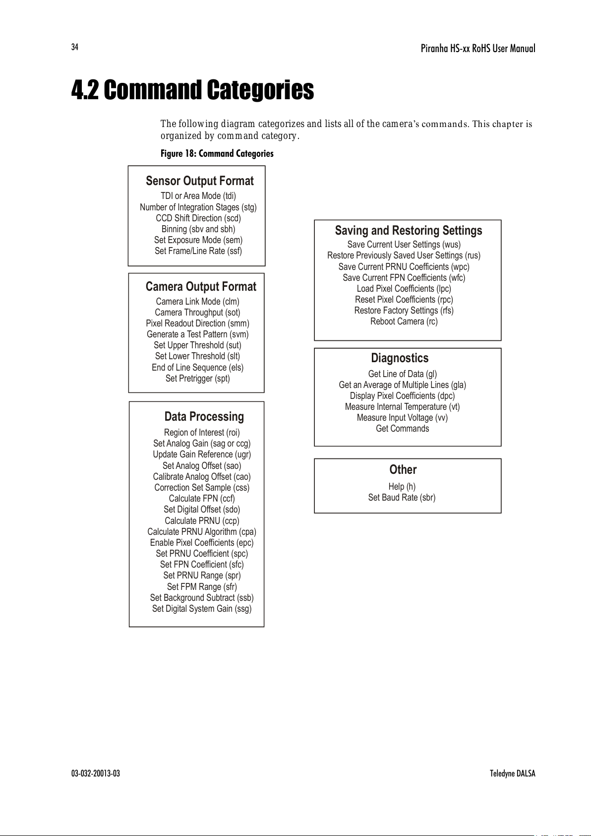
4.2 Command Categories
The following diagram categorizes and lists all of the camera’s commands. Th is ch apter is
organized by command category.
Figure 18: Command Categories
Sensor Output Format
Data Processing
Camera Output Format
TDI or Area Mode (tdi)
Number of Integration Stages (stg)
CCD Shift Direction (scd)
Binning (sbv and sbh)
Set Exposure Mode (sem)
Set Frame/Line Rate (ssf)
Region of Interest (roi)
Correction Set Sample (css)
Enable Pixel Coefficients (epc)
Set PRNU Coefficient (spc)
Set FPN Coefficient (sfc)
Set PRNU Range (spr)
Set FPM Range (sfr)
Set Analog Gain (sag or ccg)
Update Gain Reference (ugr)
Set Analog Offset (sao)
Calibrate Analog Offset (cao)
Calculate FPN (ccf)
Set Digital Offset (sdo)
Calculate PRNU (ccp)
Calculate PRNU Algorithm (cpa)
Set Background Subtract (ssb)
Set Digital System Gain (ssg)
Camera Link Mode (clm)
Camera Throughput (sot)
Pixel Readout Direction (smm)
Set Upper Threshold (sut)
Set Lower Threshold (slt)
Generate a Test Pattern (svm)
End of Line Sequence (els)
Set Pretrigger (spt)
Save Current User Settings (wus)
Restore Previously Saved User Settings (rus)
Save Current PRNU Coefficients (wpc)
Save Current FPN Coefficients (wfc)
Load Pixel Coefficients (lpc)
Reset Pixel Coefficients (rpc)
Restore Factory Settings (rfs)
Reboot Camera (rc)
Saving and Restoring Settings
Diagnostics
Get Line of Data (gl)
Get an Average of Multiple Lines (gla)
Display Pixel Coefficients (dpc)
Measure Internal Temperature (vt)
Measure Input Voltage (vv)
Get Commands
Other
Help (h)
Set Baud Rate (sbr)
All manuals and user guides at all-guides.com

Piranha HS-xx RoHS User Manual
Teledyne DALSA 03-032-20013-03
35
4.3 Sensor Output Format
4.3.1 Selecting TDI or Area Mode Operation
The Piranha HS-xx cameras have the ability to operate in both TDI and Area Mode.
In Area Mode, the camera operates as an area array camera using a two dimensional array
of pixels. Area Mode is useful for aligning the camera to your web direction or when you
need a rectangular 2D image and the lighting supports a full frame imager.
In TDI Mode, the camera operates as a TDI high sensitivity line scan camera and
combines multiple exposures of an object into one high -resolution result.
The camera stores user settings for Area Mode and TDI Mode separately, allowing you to
switch between Area and TDI mode without losing settings specific to each mode. See
section 4.6 Saving and Restoring Settings for an explanation on how user settings are
stored and retrieved.
NOTE: Sensor cosmetic specifications for Area Mode of operation are neither tested nor
guaranteed
Purpose:
Selects th e camera’s operatin g mod e. Area M od e is u seful for
aligning and focusing your camera.
Syntax:
tdi i
Syntax Elements:
i
0 Area mode
1
TDI mode
Notes:
Remember to save your user settings before changing mode.
Sending the tdi command always restores your last saved user
settings for the mode of operation requested even if you are
already operating in the requested mode. See section 4.6 Saving
and Restoring Settings for an explanation on how user settings
are stored and retrieved for each mode.
Flat field correction is not available in Area Mode
Example
tdi 1
All manuals and user guides at all-guides.com

Piranha HS-xx RoHS User Manual
03-032-20013-03 Teledyne DALSA
36
4.2 Selecting the Number of CCD Integration Stages
Purpose:
In TDI Mode, this command ad justs the sensitivity level in your
camera by setting the number of CCD integration stages. In Area
Mode, the vertical height of the image sensor is controlled by the
number of stages.
Syntax:
stg m
Syntax Elements:
m
Number of stages to use. Available values (not including the
HS-82 model) are 16, 32, 48, 64, 80, and 96. Factory setting is
96.
Available values for the HS-82 model are 8, 16, 24, 32, 40, and
48 (default).
Example
stg 64
A note on stage selection (stg) and the HS-82 model of camera:
The sensitivity level of a camera can be adjusted by setting the number of CCD
integration stages. For such purpose, the standard HS-80-08K80-00-R camera has six
different allowable settings: 16, 32, 48, 64, 80 and 96. With modifications to the binning
setup, the HS-82-04k80-00-R camera retains this feature of the standard camera, but the
number of stages is halved (8, 16, 24, 32, 40 and 48) to reflect this change.
All manuals and user guides at all-guides.com
all-guides.com

Piranha HS-xx RoHS User Manual
Teledyne DALSA 03-032-20013-03
37
4.3.3 Setting the Camera’s CCD Shift Direction
Purpose:
When in TDI Mode, selects the forward or reverse CCD shift
direction or external direction control. This accommodates object
direction change on a web and allows you to mount the camera
―u p side d ow n‖.
In Area Mode, selects the vertical readout direction. This allows
you to mirror the image vertically or mount the cam er a ―u psid e
dow n ‖.
Syntax:
scd i
Syntax Elements:
i
Readout direction. Allowable values are:
0 = Forward CCD shift direction.
1 = Reverse CCd shift direction.
2 = Externally controlled direction control via Camera Link
control CC3 (CC3=1 forward, CC3=0 reverse). Available only
in TDI Mode.
Notes:
The follow ing user settings are stored separately for forward
and reverse direction; analog gain, analog offset, digital gain,
digital offset, background subtract, and pixel coefficients.
These settings are automatically loaded when you switch
direction. All other settings are common to both directions.
See the following figures for an illustration of CCD shift
direction in relation to object movement.
Note that some commands that require longer processing
time, like ccg, delay implementation of an external direction
change.
Example
scd 1
Figure 19: Object Movement and Camera Direction Example using 4k Model and an Inverting Lens
Direction of
Object Movement
Camera should operate in
Reverse CCD Shift Direction
scd 1
Direction of
Object Movement
Camera should operate in
Forward CCD Shift Direction
scd 0
8K orientation reference
All manuals and user guides at all-guides.com

Piranha HS-xx RoHS User Manual
03-032-20013-03 Teledyne DALSA
38
4.3.4 Increasing Sensitivity with Binning
Binn ing increases th e camera’s light sensitivity by decreasing horizontal an d / or vertical
resolution—the charge collected by adjacent pixels is added together. Binning is also
useful for increasing frame rate (vertical binning) or increasing the pixel pitch. For
example, if you set your vertical binning to 2 and your horizontal binning to 2, your pixel
size increases from 7µm x 7µm (no binning) to 14µm x 14µm (2x2 binning).
Figure 20: 2x2 Binning in Area Mode
Setting Horizontal Binning
Purpose:
Increases the horizontal pixel pitch and light sensitivity by
decreasing horizontal resolution. The amount of data being sent
from the camera is reduced by the horizontal binning factor.
Different framegrabber files are needed for different horizontal
binning factors.
Syntax:
sbh m
Syntax Elements:
m
Horizontal binning value. Available values are 1 (factory
setting, no binning) 2, 4, or 8.
Notes:
If you are using horizontal binning, the min, max, and mean
statistics generated by the gl or gla command are for every
second pixel (or valid data) only (e.g., if sbh 2, every second
pixel).
For optimal flat field correction, you should rerun the ccp and
ccf commands after changing binning values.
Changing binning values does not automatically alter gain,
frame rate generation, or other functions of the camera.
Pixel numbering remains unchanged for the roi, gl, gla,
dpc, gfc, sfc, gpc, and spc commands. Refer to Figure 21
for an explanation of pixel numbering and pixel start and stop
values when using a region of interest.
Example:
sbh 2
All manuals and user guides at all-guides.com
Piranha HS-xx RoHS User Manual
Teledyne DALSA 03-032-20013-03
39
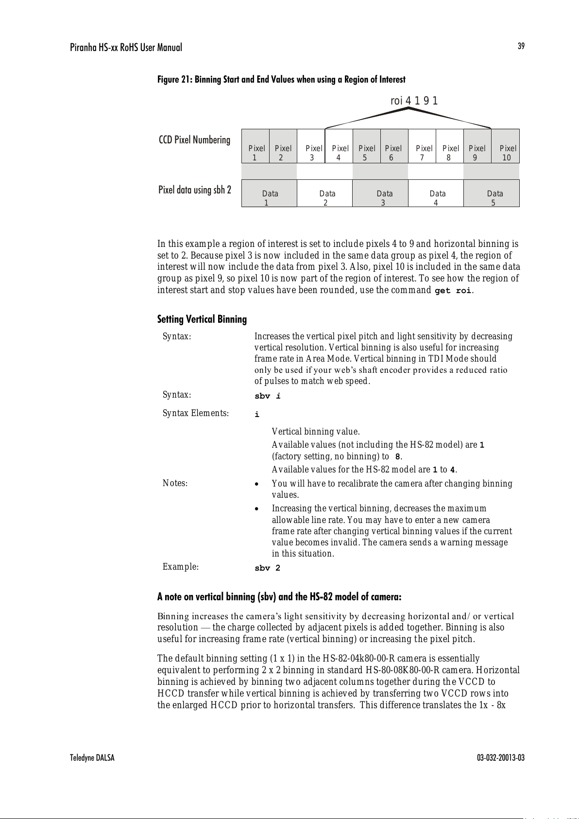
Figure 21: Binning Start and End Values when using a Region of Interest
In this example a region of interest is set to include pixels 4 to 9 and horizontal binning is
set to 2. Because pixel 3 is now included in the same data group as pixel 4, the region of
interest will now include the data from pixel 3. Also, pixel 10 is included in the same data
group as pixel 9, so pixel 10 is now part of the region of interest. To see how the region of
interest start and stop values have been rounded, use the command get roi.
Setting Vertical Binning
Syntax:
Increases the vertical pixel pitch and light sensitivity by decreasing
vertical resolution. Vertical binning is also useful for increasing
frame rate in Area Mode. Vertical binning in TDI Mode should
on ly be used if y ou r w eb’s shaft encod er p rovides a red uced ratio
of pulses to match web speed.
Syntax:
sbv i
Syntax Elements:
i
Vertical binning value.
Available values (not including the HS-82 model) are 1
(factory setting, no binning) to 8.
Available values for the HS-82 model are 1 to 4.
Notes:
You will have to recalibrate the camera after changing binning
values.
Increasing the vertical binning, decreases the maximum
allowable line rate. You may have to enter a new camera
frame rate after changing vertical binning values if the current
value becomes invalid. The camera sends a warning message
in this situation.
Example:
sbv 2
A note on vertical binning (sbv) and the HS-82 model of camera:
Binn ing increases th e camera’s light sensitivity by decreasing horizontal an d / or vertical
resolution — the charge collected by adjacent pixels is added together. Binning is also
useful for increasing frame rate (vertical binning) or increasing the pixel pitch.
The default binning setting (1 x 1) in the HS-82-04k80-00-R camera is essentially
equivalent to performing 2 x 2 binning in standard HS-80-08K80-00-R camera. Horizontal
binning is achieved by binning two adjacent columns together during the VCCD to
HCCD transfer while vertical binning is achieved by transferring two VCCD rows into
the enlarged HCCD prior to horizontal transfers. This difference translates the 1x - 8x
Pixel 1 Pixel 2 Pixel 3 Pixel 4 Pixel 5 Pixel 6 Pixel 7 Pixel 8 Pixel 9 Pixel
10
Data
1 Data 2 Data 3 Data 4 Data
5
CCD Pixel Numbering
Pixel data using sbh 2
roi 4 1 9 1
All manuals and user guides at all-guides.com

Piranha HS-xx RoHS User Manual
03-032-20013-03 Teledyne DALSA
40
binning capability of HS-80-08K80-00-R camera to 1x - 4x binning in the HS-82-04k80-00-R
camera.
4.3.5 Exposure Mode and Line/Frame Rate
How to Set Exposure Mode and Line/Frame Rate
You have a choice of operating the camera in one of two exposure modes. Depending on
your mode of operation, the camera’s line/ frame rate (synchronization) can be generated
internally through the software command ssf or set externally with an EXSYNC signal
(CC1). When operating in TDI Mode, it is important that the line rate used matches the
web speed. Failure to match the web speed will result in smearing.
To select how you want the camera’s line/frame rate to be generated:
1. You must first set the camera’s exposur e mode using the sem command. Refer to section
Setting the Exposure Mode below for details.
2. Next, if using mode 7, use the command ssf to set the line/ frame rate. Refer to section
Setting Frame Rate for details.
Setting the Exposure Mode
Purpose:
Sets the camera’s exp osure mod e allowing you to con trol your
sync and line/ frame rate generation.
Syntax:
sem m
Syntax Elements:
m
Exposure mode to use. Factory setting is 7.
Notes:
Refer to Table 10: Piranha HS Exposure Modes for a quick list
of available modes or to the following sections for a more
detailed explanation including timing diagrams.
To obtain the current value of the exposure mode, use the
command gcp or get sem.
When setting the camera to external signal modes,
EXSYNC must be supplied.
Refer to section 4.5.1 for more information on how to
operate your camera in TDI or Area Mode.
Exposure Modes are saved separately for TDI Mode and
Area Mode. Refer to section 4.6 Saving and Restoring
Settings for more information on how to save camera
settings.
Related Commands:
ssf
Example:
sem 3
All manuals and user guides at all-guides.com
Piranha HS-xx RoHS User Manual
Teledyne DALSA 03-032-20013-03
41
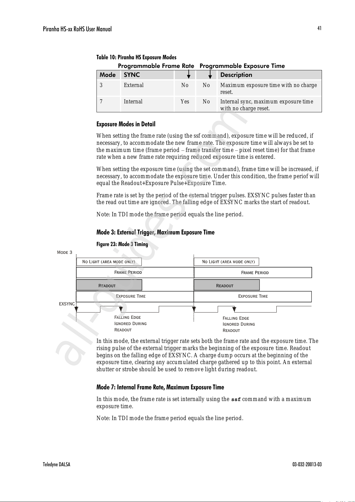
Table 10: Piranha HS Exposure Modes
Programmable Frame Rate Programmable Exposure Time
Mode
SYNC
Description
3
External
No
No
Maximum exposure time with no charge
reset.
7
Internal
Yes
No
Internal sync, maximum exposure time
with no charge reset.
Exposure Modes in Detail
When setting the frame rate (using the ssf command), exposure time will be reduced, if
necessary, to accommodate the new frame rate. The exposure time will always be set to
the maximum time (frame period – frame transfer time – pixel reset time) for that frame
rate when a new frame rate requiring reduced exposure time is entered.
When setting the exposure time (using the set command), frame time will be increased, if
necessary, to accommodate the exposure time. Under this condition, the frame periof will
equal the Readout+Exposure Pulse+Exposure Time.
Frame rate is set by the period of the external trigger pulses. EXSYNC pulses faster th an
the read out time are ignored. The falling edge of EXSYNC marks the start of readout.
Note: In TDI mode the frame period equals the line period.
Mode 3: External Trigger, Maximum Exposure Time
Figure 23: Mode 3 Timing
Frame Period
Exposure Time
Frame Period
Readout
Exposure Time
EXSYNC
Falling Edge
Ignored During
Readout
Readout
Mode 3
Falling Edge
Ignored During
Readout
In this mode, the external trigger rate sets both the frame rate and the exposure time. The
rising pulse of the external trigger marks the beginning of the exposure time. Readout
begins on the falling edge of EXSYNC. A charge dump occurs at the beginning of the
exposure time, clearing any accumulated charge gathered up to this point. An external
shutter or strobe should be used to remove light during readout.
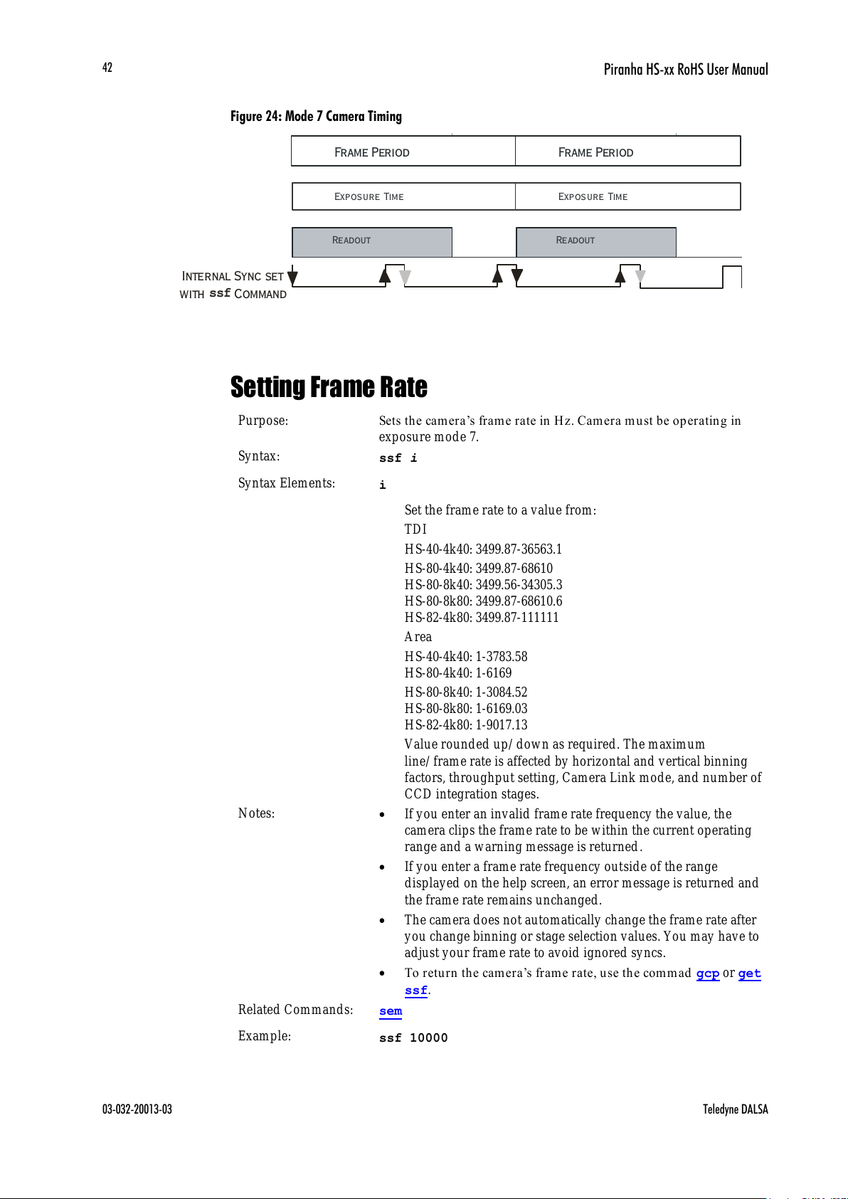
Mode 7: Internal Frame Rate, Maximum Exposure Time
In this mode, the frame rate is set internally using the ssf command with a maximum
exposure time.
Note: In TDI mode the frame period equals the line period.
All manuals and user guides at all-guides.com
all-guides.com
Piranha HS-xx RoHS User Manual
03-032-20013-03 Teledyne DALSA
42
Figure 24: Mode 7 Camera Timing
Exposure Time
Readout
Internal Sync set
ssf
Frame Period
Exposure Time
Readout
Frame Period
Setting Frame Rate
Purpose:
Sets the camera’s frame rate in Hz. Cam er a m u st be op er ating in
exposure mode 7.
Syntax:
ssf i
Syntax Elements:
i
Set the frame rate to a value from:
TDI
HS-40-4k40: 3499.87-36563.1
HS-80-4k40: 3499.87-68610
HS-80-8k40: 3499.56-34305.3
HS-80-8k80: 3499.87-68610.6
HS-82-4k80: 3499.87-111111
Area
HS-40-4k40: 1-3783.58
HS-80-4k40: 1-6169
HS-80-8k40: 1-3084.52
HS-80-8k80: 1-6169.03
HS-82-4k80: 1-9017.13
Value round ed up/ down as required. The maximum
line/ frame rate is affected by horizontal and vertical binning
factors, throughput setting, Camera Link mode, and number of
CCD integration stages.
Notes:
If you enter an invalid frame rate frequency the value, the
camera clips the frame rate to be within the current operating
range and a warning message is returned.
If you enter a frame rate frequency outside of the range
displayed on the help screen, an error message is returned and
the frame rate remains unchanged.
The camera does not automatically change the frame rate after
you change binning or stage selection values. You may have to
adjust your frame rate to avoid ignored syncs.
To retu rn the cam era’s fram e rate, u se th e commad gcp or get
ssf.
Related Commands:
sem
Example:
ssf 10000
All manuals and user guides at all-guides.com

Piranha HS-xx RoHS User Manual
Teledyne DALSA 03-032-20013-03
43
4.4 Camera Output Format
4.4.1 How to Configure Camera Output
The Piranha HS cameras offer great flexibility when configuring your camera output.
Using the clm com m and, you determine th e cam era’s Cam era Lin k con figuration,
number of output taps, and bit depth. Using the sot command, you determine the
cam era’s ou tp u t rate. These tw o com m and s w ork together to determine your final camera
output configuration.
You can further configure your readout using the smm com m and to select the cam era’s
pixel readout direction.
The following tables summarize the possible camera configurations for each of the HS-xx
camera models. Refer to the figure below for a description on how to select your camera
output.
Figure 25: How to Read the Camera Link Tables
Camera Link Mode Configuration (Controlled by
clm
command)
Readout Direction(Controlled by
smm command)
Pixel Rate
Configuration
(Controlled by sot
command)
Command
Camera Link
Configuration
Camera Link Taps Bit
Depth
smm 0 increment =1
smm 1 increment =
-1
clm 2
Base
2 Camera Link taps
where:
1 = CCD taps 1 +2
2 = CCD taps 3+4
8
smm 0
=CL tap 1 (1-2048)
CL tap 2 (2049-4096)
smm 1 = CL tap 1
(4096-2049)
CL tap 2 (2048-1)
sot 160 = 80 MHz
strobe
(max line rate
36kHz)
sot 80 = 40 MHz
strobe
(Max line rate
18kHz)
Find the rows in the table
with a line rate greater than
or equal to your desired
line rate.
From the rows determined in part A,
find the values in the table
with a throughput greater than or equal
to your your required throughput.
sot
From the rows determined by
part B, find the Camera Link modes
with your desired bit depth.
From the remaining rows determined
in part C, select an acceptable Camera Link
configuration. If none of the remaining
configurations are acceptable for your system,
you will have to reduce your bit depth
or line rate.
Set the pixel readout direction.
Note: Horizontal binning reduces
the number of pixels sent to the
frame grabber by the binning factor.
Note: In the following tables, a CCD tap refers to the actual physical taps on the sensor,
while the Camera Link taps refer to the way the data is configured for output over
Camera Link. For a diagram illustrating sensor taps, see section 1.3 Image Sensor.
All manuals and user guides at all-guides.com

Piranha HS-xx RoHS User Manual
03-032-20013-03 Teledyne DALSA
44
Table 11: HS-40-04k40 Data Readout Configurations
Camera Link Mode Configuration (Controlled by clm
command)
Readout Direction
(Controlled by smm
command)
Pixel Rate
Configuration
(Controlled by sot
command)
Command
Camera Link
Configuration
Camera Link Taps
Bit
Depth
smm 0 increment =1
smm 1 increment = -1
clm 2
Base
2 Camera Link taps
where:
1 = CCD taps 1+2
2 = CCD taps 3+4
8
smm 0 =CL tap 1 (1-2048)
CL tap 2 (2049-4096)
smm 1 = CL tap 1 (4096-2049)
CL tap 2 (2048-1)
sot 160 = 80 MHz
strobe
(max line rate
36563Hz)
sot 80 = 40 MHz
strobe
(Max line rate
19166Hz)
clm 3
Base
2 Camera Link taps
where:
1 = CCD taps 1+2
2 = CCD taps 3+4
12
smm 0 = CL tap 1 (1-2048)
CL tap 2 (2049-4096)
smm 1 = CL tap 1 (4096-2049)
CL tap 2 (2048-1)
sot 160 = 80 MHz
strobe
(max line rate
36563Hz)
sot 80 = 40 MHz
strobe
(Max line rate
19166Hz)
clm 15
Medium
4 Camera Link taps
where:
1 = CCD tap 1
2 = CCD tap 2
3 = CCD tap 3
4 = CCD tap 4
8
smm 0 = CL tap 1 (1-1024)
CL tap 2 (1025-2048)
CL tap 3 (2049-3072)
CL tap 4 (3073-4096)
smm 1 =CL tap 1 (4096-3073)
CL tap 2 (3072-2049)
CL tap 3 (2048-1025)
CL tap 4 (1024-1)
sot 160 = 40 MHz
strobe
(max line rate
36563Hz)
clm 16
Medium
4 Camera Link taps
where:
1 = CCD tap 1
2 = CCD tap 2
3 = CCD tap 3
4 = CCD tap 4
12
smm 0 = CL tap 1(1-1024)
CL tap 2(1025-2048)
CL tap 3(2049-3072)
CL tap 4(3073-4096)
smm 1 = CL tap 1(4096-3073)
CL tap 2(3072-2049)
CL tap 3(2048-1025)
CL tap 4(1024-1)
sot 160 = 40 MHz
strobe
(max line rate
36563Hz)
All manuals and user guides at all-guides.com

Piranha HS-xx RoHS User Manual
Teledyne DALSA 03-032-20013-03
45
Table 12: HS-80-04k40 Configurations
Camera Link Mode Configuration (Controlled by clm command)
Readout Direction (Controlled by
smm command)
Pixel Rate Configuration (Controlled by
sot command)
Command
Camera Link
Configuration
Camera Link Taps
Bit
Depth
clm 15
Medium
4 Camera Link taps
where:
1 = CCD tap 1+2
2 = CCD tap 3+4
3 = CCD tap 5+6
4 = CCD tap 7+8
8
smm 0 = CL tap 1(1-1024)
CL tap 2(1025-2048)
CL tap 3(2049-3072)
CL tap 4(3073-4096)
smm 1 = CL tap 1(4096-3073)
CL tap 2(3072-2049)
CL tap 3(2048-1025)
CL tap 4(1024-1)
sot 160 = 40 MHz strobe
(max line rate 37629Hz)
sot 320 = 80 MHz strobe
(max line rate 68610Hz)
clm 16
Medium
4 Camera Link taps
where:
1 = CCD tap 1+2
2 = CCD tap 3+4
3 = CCD tap 5+6
4 = CCD tap 7+8
12
smm 0 = CL tap 1(1-1024)
CL tap 2(1025-2048)
CL tap 3(2049-3072)
CL tap 4(3073-4096)
smm 1 = CL tap 1(4096-3073)
CL tap 2(3072-2049)
CL tap 3(2048-1025)
CL tap 4(1024-1)
sot 160 = 40 MHz strobe
(max line rate 37629Hz)
sot 320 = 80 MHz strobe
(max line rate 68610Hz)
clm 21
Full
8 Camera Link taps
where:
1 = CCD tap 1
2 = CCD tap 2
3 = CCD tap 3
4 = CCD tap 4
5 = CCD tap 5
6 = CCD tap 6
7 = CCD tap 7
8 = CCD tap 8
8
smm 0 = CL tap 1(1-512)
CL tap 2(513-1024)
CL tap 3(1025-1536)
CL tap 4(1537-2048)
CL tap 5(2049-2560)
CL tap 6(2561-3072)
CL tap 7(3073-3584)
CL tap 8(3585-4096)
smm 1 = CL tap 1(4096-3585)
CL tap 2(3584-3073)
CL tap 3(3072-2561)
CL tap 4(2560-2049)
CL tap 5(2048-1537)
CL tap 6(1536-1025)
CL tap 7(1024-513)
CL tap 8(512-1)
sot 320 = 40 MHz strobe
(max line rate 68610Hz)
All manuals and user guides at all-guides.com

Piranha HS-xx RoHS User Manual
03-032-20013-03 Teledyne DALSA
46
Table 13: HS-80-08k40 Configurations
Camera Link Mode Configuration (Controlled by clm command)
Readout Direction (Controlled by
smm command)
Pixel Rate
Configuration
(Controlled by sot
command)
Command
Camera Link
Configuration
Camera Link Taps
Bit
Depth
clm 15
Medium
4 Camera Link taps
where:
1 = CCD tap
1+2+3+4
2 = CCD tap
5+6+7+8
3 = CCD tap
9+10+11+12
4 = CCD tap
13+14+15+16
8
smm 0 = CL tap 1(1-2048)
CL tap 2(2049-4096)
CL tap 3(4097-6144)
CL tap 4(6145-8192)
smm 1 = CL tap 1(8192-6145)
CL tap 2(6144-4097)
CL tap 3(4096-2049)
CL tap 4(2048-1)
sot 80 = 20 MHz
strobe
(max line rate
9583Hz)
sot 160 = 40 MHz
strobe
(max line rate
19157Hz)
clm 16
Medium
4 Camera Link taps
where:
1 = CCD tap
1+2+3+4
2 = CCD tap
5+6+7+8
3 = CCD tap
9+10+11+12
4 = CCD tap
13+14+15+16
12
smm 0 = CL tap 1(1-2048)
CL tap 2(2049-4096)
CL tap 3(4097-6144)
CL tap 4(6145-8192)
smm 1 = CL tap 1(8192-6145)
CL tap 2(6144-4097)
CL tap 3(4096-2049)
CL tap 4(2048-1)
sot 80 = 20 MHz
strobe
(max line rate
9583Hz)
sot 160 = 40 MHz
strobe
(max line rate
19157Hz)
clm 21
Full
8 Camera Link taps
where:
1 = CCD tap 1+2
2 = CCD tap 3+4
3 = CCD tap 5+6
4 = CCD tap 7+8
5 = CCD tap 9+10
6 = CCD tap 11+12
7 = CCD tap 13+14
8 = CCD tap 15+16
8
smm 0 = CL tap 1(1-1024)
CL tap 2(1025-2048)
CL tap 3(2049-3072)
CL tap 4(3073-4096)
CL tap 5(4097-5120)
CL tap 6(5121-6144)
CL tap 7(6145-7168)
CL tap 8(7169-8192)
smm 1 = CL tap 1(8192-7169)
CL tap 2(7168-6145)
CL tap 3(6144-5121)
CL tap 4(5120-4097)
CL tap 5(4096-3073)
CL tap 6(3072-2049)
CL tap 7(2048-1025)
CL tap 8(1024-1)
sot 160 = 20 MHz
strobe
(max line rate
18814Hz)
sot 320 = 40 MHz
strobe
(max line rate
34305Hz)
All manuals and user guides at all-guides.com
all-guides.com

Piranha HS-xx RoHS User Manual
Teledyne DALSA 03-032-20013-03
47
Table 14: HS-80-08k80 Configurations
Camera Link Mode Configuration (Controlled by clm command)
Readout Direction (Controlled by
smm command)
Pixel Rate
Configuration
(Controlled by sot
command)
Command
Camera Link
Configuration
Camera Link Taps
Bit
Depth
clm 15
Medium
4 Camera Link taps
where:
1 = CCD tap
1+2+3+4
2 = CCD tap
5+6+7+8
3 = CCD tap
9+10+11+12
4 = CCD tap
13+14+15+16
8
smm 0 = CL tap 1(1-2048)
CL tap 2(2049-4096)
CL tap 3(4097-6144)
CL tap 4(6145-8192)
smm 1 = CL tap 1(8192-6145)
CL tap 2(6144-4097)
CL tap 3(4096-2049)
CL tap 4(2048-1)
sot 320 = 80 MHz
strobe
(max rate 38314Hz)
sot 160 = 40 MHz
strobe
(max line rate
19166Hz)
clm 16
Medium
4 Camera Link taps
where:
1 = CCD tap
1+2+3+4
2 = CCD tap
5+6+7+8
3 = CCD tap
9+10+11+12
4 = CCD tap
13+14+15+16
12
smm 0 = CL tap 1(1-2048)
CL tap 2(2049-4096)
CL tap 3(4097-6144)
CL tap 4(6145-8192)
smm 1 = CL tap 1(8192-6145)
CL tap 2(6144-4097)
CL tap 3(4096-2049)
CL tap 4(2048-1)
sot 320 = 80 MHz
strobe
(max line rate
38314Hz)
sot 160 = 40 MHz
strobe
(max line rate
19166Hz)
clm 21
Full
8 Camera Link taps
where:
1 = CCD tap 1+2
2 = CCD tap 3+4
3 = CCD tap 5+6
4 = CCD tap 7+8
5 = CCD tap 9+10
6 = CCD tap 11+12
7 = CCD tap 13+14
8 = CCD tap 15+16
8
smm 0 = CL tap 1(1-1024)
CL tap 2(1025-2048)
CL tap 3(2049-3072)
CL tap 4(3073-4096)
CL tap 5(4097-5120)
CL tap 6(5121-6144)
CL tap 7(6145-7168)
CL tap 8(7169-8192)
smm 1 = CL tap 1(8192-7169)
CL tap 2(7168-6145)
CL tap 3(6144-5121)
CL tap 4(5120-4097)
CL tap 5(4096-3073)
CL tap 6(3072-2049)
CL tap 7(2048-1025)
CL tap 8(1024-1)
sot 640 = 80 MHz
strobe (HS-80-08k80
only)
(max line rate
68610Hz)
sot 320 = 40 MHz
strobe
(max line rate
37629Hz)
All manuals and user guides at all-guides.com
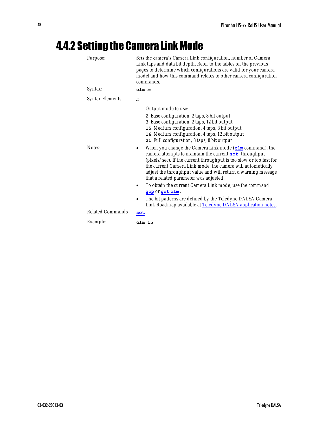
Piranha HS-xx RoHS User Manual
03-032-20013-03 Teledyne DALSA
48
4.4.2 Setting the Camera Link Mode
Purpose:
Sets the camera’s Camera Link con figuration, number of Camera
Link taps and data bit depth. Refer to the tables on the previous
pages to determine which configurations are valid for your camera
model and how this command relates to other camera configuration
commands.
Syntax:
clm m
Syntax Elements:
m
Output mode to use:
2: Base configuration, 2 taps, 8 bit output
3: Base configuration, 2 taps, 12 bit output
15: Medium configuration, 4 taps, 8 bit output
16: Medium configuration, 4 taps, 12 bit output
21: Full configuration, 8 taps, 8 bit output
Notes:
When you change the Camera Link mode (clm command), the
camera attempts to maintain the current sot throughput
(pixels/ sec). If the current throughput is too slow or too fast for
the current Camera Link mode, the camera will automatically
adjust the throughput value and will return a warning message
that a related parameter was adjusted.
To obtain the current Camera Link mode, use the command
gcp or get clm.
The bit patterns are defined by the Teledyne DALSA Camera
Link Roadmap available at Teledyne DALSA application notes.
Related Commands
sot
Example:
clm 15
All manuals and user guides at all-guides.com

Piranha HS-xx RoHS User Manual
Teledyne DALSA 03-032-20013-03
49
4.4.3 Setting the Camera Throughput
Purpose:
Works in conjunction with the clm command (see previous) and
determines the throughput of the camera. Refer to the tables in
section 4.4.1 How to Configure Camera Output to determine which
configurations are valid for your camera model and how this
command relates to other camera configuration commands.
Syntax:
sot m
Syntax Elements:
m
Output throughput. Allowable values are:
80 = 4 taps at 20MHz or 2 taps at 40MHz
160 = 2 taps at 80MHz or 4 taps at 40MHz
320 = 4 taps at 80MHz or 8 taps at 40MHz
640 = 8 taps at 80MHz
Notes:
Throughput is calculated as:
Throughput= (Number of Camera Link Taps) x (Camera Link
Pixel Rate in MHz)
To obtain the throughput setting, use the command gcp or get
clm.
Throughput values are clipped if the camera is unable to
maintain the current throughput setting and a warning
message is displayed.
Refer to the tables in section 4.4.1 How to Configure Camera
Output to determine which configurations are valid for your
camera model.
Related Commands
clm
Example:
sot 160
4.4.4 Setting the Pixel Readout Direction
Purpose:
Sets the tap readout from left to right or from right to left. This
command is useful if the camera must be mounted upside down.
Syntax:
smm i
Syntax Elements:
i
Readout direction. Allowable values are:
0 = All pixels are read out from left to right.
1 = All pixels are read out from right to left.
Notes:
To obtain the current readout direction, use the command gcp
or get smm.
This command is available in both TDI and Area Mode.
Refer to the following figures and tables for an explanation of
pixel readout and mirror direction.
Refer to section 1.3 Image Sensor for sensor architecture
diagrams that illustrate sensor readout direction.
All manuals and user guides at all-guides.com
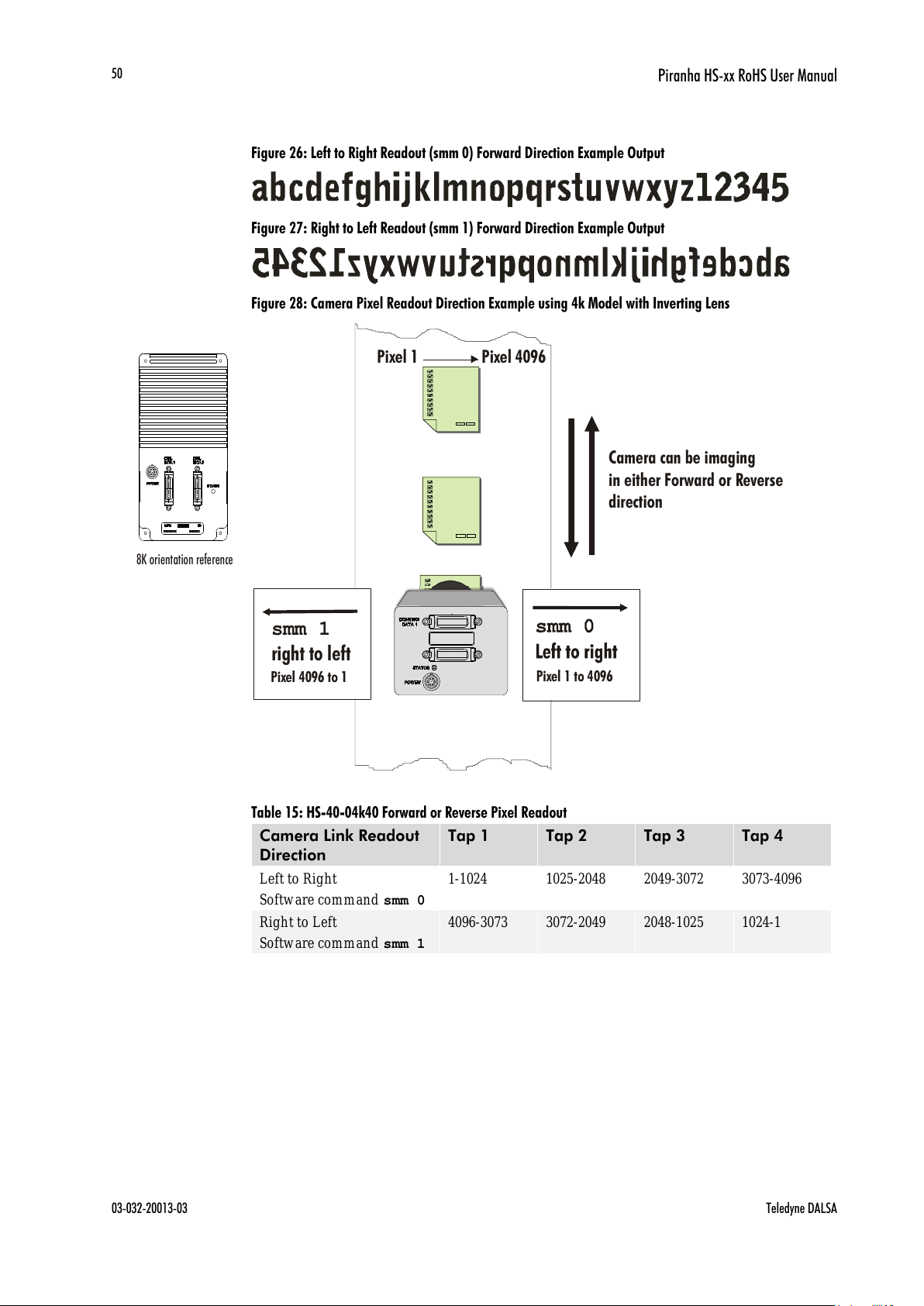
Piranha HS-xx RoHS User Manual
03-032-20013-03 Teledyne DALSA
50
Figure 26: Left to Right Readout (smm 0) Forward Direction Example Output
Figure 27: Right to Left Readout (smm 1) Forward Direction Example Output
Figure 28: Camera Pixel Readout Direction Example using 4k Model with Inverting Lens
smm 1
right to left
Pixel 1 to 4096
Pixel 4096 to 1
Camera can be imaging
in either Forward or Reverse
direction
Pixel 1
Pixel 4096
Table 15: HS-40-04k40 Forward or Reverse Pixel Readout
Camera Link Readout
Direction
Tap 1
Tap 2
Tap 3
Tap 4
Left to Right
Software command smm 0
1-1024
1025-2048
2049-3072
3073-4096
Right to Left
Software command smm 1
4096-3073
3072-2049
2048-1025
1024-1
8K orientation reference
All manuals and user guides at all-guides.com

Piranha HS-xx RoHS User Manual
Teledyne DALSA 03-032-20013-03
51
Table 16: HS-80-04k40 Forward or Reverse Pixel Readout
Readout Direction
Tap 1
Tap 2
Tap 3
Tap 4
Tap 5
Tap 6
Tap 7
Tap 8
Left to Right
Software command
smm 0
1-512
513-1024
1025-1536
1537-2048
2049-2560
2561-3072
3073-3584
3585-
4096
Right to Left
Software command
smm 1
4096-3585
3584-3073
3072-2561
2560-2049
2048-1537
1536-1025
1024-513
512-1
Table 17: HS-80-08k40, HS-80-08k80 Forward or Reverse Pixel Readout
Readout Direction
Tap 1
Tap 2
Tap 3
Tap 4
Tap 5
Tap 6
Tap 7
Tap 8
Left to Right
Software command
smm 0
1-1024
1025-2048
2049-3072
3073-4096
4097-5120
5121-6144
6145-7168
7169-
8192
Right to Left
Software command
smm 1
8192-7169
7168-6145
6144-5121
5120-4097
4096-3073
3072-2049
2048-1025
1024-1
4.4.5 Setting a Pretrigger
Purpose:
A pretrigger may be required for some frame grabbers.
Syntax:
spt i
Syntax Elements:
i
Pretrigger in a range from 0 to 16.
4.5 Data Processing
4.5.1 Setting a Region of Interest
Purpose:
Sets the pixel range used to collect the end -of-line statistics and
sets the region of pixels used in the ccg, cao, cpa, gl, gla, ccf,
and ccp commands.
In most applications, the field of view exceeds the required object
size and these extraneous areas should be ignored. It is
recommended that you set the region of interest a few pixels
inside the actual useable image.
Syntax:
roi x1 y1 x2 y2
Syntax Elements:
x1
Column start number. Must be less than or equal to the
column end number in a range from 1 to (column resolution –
1).
y1
Row start number. Must be less than or equal to the row end
number in a range from 1 to (row end number – 1) except in
TDI Mode where y1 must be 1.
x2
Column end number. Must be greater than or equal to the
All manuals and user guides at all-guides.com
all-guides.com
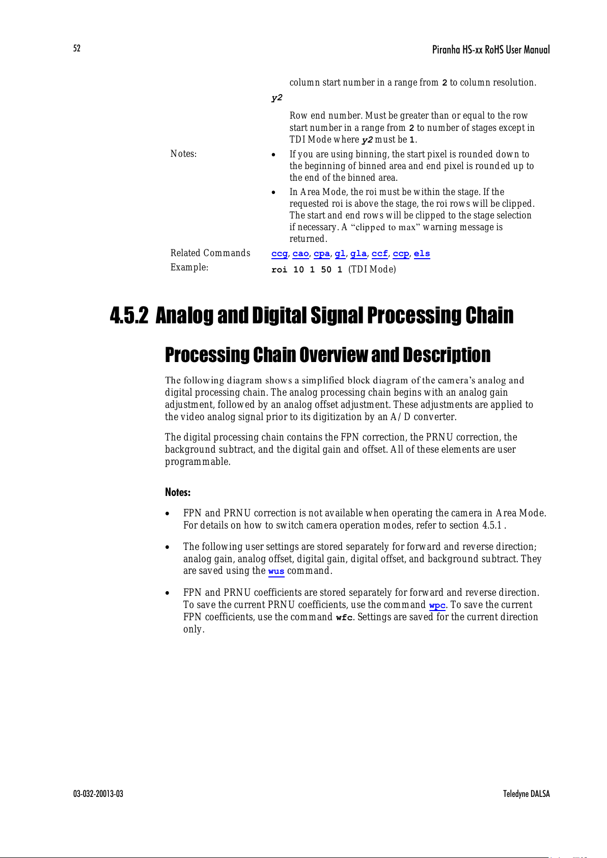
Piranha HS-xx RoHS User Manual
03-032-20013-03 Teledyne DALSA
52
column start number in a range from 2 to column resolution.
y2
Row end number. Must be greater than or equal to the row
start number in a range from 2 to number of stages except in
TDI Mode where y2 must be 1.
Notes:
If you are using binning, the start pixel is rounded down to
the beginning of binned area and end pixel is round ed up to
the end of the binned area.
In Area Mode, the roi must be within the stage. If the
requested roi is above the stage, the roi rows will be clipped.
The start and end rows will be clipped to the stage selection
if necessary. A ―clip ped to m ax‖ warning message is
returned.
Related Commands
ccg, cao, cpa, gl, gla, ccf, ccp, els
Example:
roi 10 1 50 1 (TDI Mode)
4.5.2 Analog and Digital Signal Processing Chain
Processing Chain Overview and Description
The follow in g diagram sh ow s a sim p lified block d iagram of the cam era’s analog and
digital processing chain. The analog processing chain begins with an analog gain
adjustment, followed by an analog offset adjustment. These adjustments are applied to
the video analog signal prior to its digitization by an A/ D converter.
The digital processing chain contains the FPN correction, the PRNU correction, the
background subtract, and the digital gain and offset. All of these elements are user
programmable.
Notes:
FPN and PRNU correction is not available when operating the camera in Area Mode.
For details on how to switch camera operation modes, refer to section 4.5.1 .
The following user settings are stored separately for forward and reverse direction;
analog gain, analog offset, digital gain, digital offset, and background subtract. They
are saved using the wus command.
FPN and PRNU coefficients are stored separately for forward and reverse direction.
To save the current PRNU coefficients, use the command wpc. To save the current
FPN coefficients, use the command wfc. Settings are saved for the current direction
only.
All manuals and user guides at all-guides.com

Piranha HS-xx RoHS User Manual
Teledyne DALSA 03-032-20013-03
53
Figure 29: Signal Processing Chain
Analog Processing
Optimizing offset performance and gain in the analog domain allows you to achieve a
better signal-to-noise ratio and dynamic range than you would achieve by trying to
optimize the offset in the digital domain. As a result, perform all analog adjustments prior
to any digital adjustments.
1. Analog gain is multiplied by the analog signal to increase the signal strength before
the A/ D conversion. It is used to take advantage of the full dynamic range of the
A/ D converter. For example, in a low light situation the brightest part of the image
may be consistently coming in at only 50% of the DN. An analog gain of 6 dB (2x) will
ensure full use of the dynamic range of the A/ D converter. Of course the noise is also
increased.
2. The an alog offset or black lev el is an ―artifi cial‖ offset introd u ced into the vid eo path
to ensure that the A/ D will function properly. The analog offset should be set so that
it is at least 3 times the rms noise value at the current gain.
Digital Processing
To optimize camera performance, digital signal processing should be completed after any
analog adjustments.
1. Fixed pattern noise (FPN) calibration (calculated using the ccf command) is used to
subtract away individual pixel dark current.
2. The digital offset (sdo command) enables the su b tr action of th e ―artificial‖ A/ D offset
(th e analog offset) so t hat ap p lication of the PRN U coefficient d oesn ’t resu lt in
artifacts at low light levels due to the offset value. You may want to set the sdo value
if you are not using FPN correction but want to perform PRNU correction.
3. Photo-Response Non-Uniformity (PRNU) coefficients are used to correct the
difference in responsivity of individual pixels (i.e. given the same amount of light
different pixels will charge up at different rates) and the change in light intensity
across the image either because of the light source or due to optical aberrations (e.g.
there many be more light in the center of the image). PRNU coefficients are
All manuals and user guides at all-guides.com
Piranha HS-xx RoHS User Manual
03-032-20013-03 Teledyne DALSA
54
multipliers and are defined to be of a value greater than or equal to 1. This ensures
that all pixels will saturate together. When using PRNU correction, it is important
that the A/ D offset and Fixed Pattern Noise (FPN) or per pixel offsets are subtracted
prior to the multiplication by the PRNU coefficient. The subtraction of these 2
components ensure that the video supplied to the PRNU multiplier is nominally zero
and zero multiplied by anything is still zero resulting in no PRNU coefficient induced
FPN. If the offset is not subtracted from the video then there will be artifacts in the
video at low light caused by the multiplication of the offset value by the PRNU
coefficients.
4. Background subtract (ssb command) and system (digital) gain (ssg command) are
used to increase image contrast after FPN and PRNU calibration. It is useful for
systems that process 8-bit data but w ant to take ad v antage of the camera’s 12-bit
digital processing chain. For example, if you find that your image is consistently
between 128 and 255DN(8-bit), you can subtract off 128 (ssb 2048) and then
multiply by 2 (ssg 0 8192) to get an output range from 0 to 255.
The following sections are organized as follows:
1. Section Analog Signal Processing provides a detailed description of all analog
processing chain commands.
2. Section Calibrating the Camera to Remove Non-Uniformity (Flat Field
Correction) provides an overview of how to perform flat field calibration.
3. Section Digital Signal Processing provides a detailed description of all digital
processing chain commands.
Analog Signal Processing: Setting Analog Gain and
Offset
All analog signal processing chain commands should be performed prior to FPN and
PRNU calibration and prior to digital signal processing commands.
Setting Analog Gain
Purpose:
Sets the camera’s an alog gain v alue. An alog gain is m u ltiplied by
the analog signal to increase the signal strength before the A/ D
conversion. It is used to take advantage of the full dynamic range
of the A/ D converter.
Syntax:
sag t f
Syntax Elements:
t
Tap selection. Use 0 for all taps or 1 to number of CCD taps
for individual tap selection.
f
Gain value in a range from –10 to +10dB.
Example:
sag 0 5.2
All manuals and user guides at all-guides.com
Piranha HS-xx RoHS User Manual
Teledyne DALSA 03-032-20013-03
55
Calibrating Camera Gain
Purpose:
Instead of manually setting the analog gain to a specific value, the
camera can determine appropriate gain values. This command
calculates and sets the analog gain according to the algorithm
determined by the first parameter.
Syntax:
ccg i t i
Syntax Elements:
i
Calibration algorithm to use.
1 = This algorithm adjusts analog gain so that 8% to 13% of
tap ROI pixels are above the specified target value.
2 = This algorithm adjusts analog gain so that the average
pixel value in tap’s ROI is equal to the specified target value.
3 = This algorithm adjusts digital gain so that the average
pixel value in tap’s ROI is equal to the specified target.
4 = This algorithm adjusts the analog gain so that the peak
tap ROI pixels are adjusted to the specified target.
t
Tap value. Use 0 for all taps or 1 to number of CCD taps for
individual tap selection.
i
Calculation target value in a range from 1024 to 4055DN
(12 bit LSB).
Notes:
All digital settings (digital offset, FPN and PRNU
coefficients), digital gain, background subtract) should be
turned off before calibrating analog gain to avoid
unpredictable results.
This function requires constant light input while executing.
To use this command, the CCD shift direction (scd) should
be set to forward (0) or reverse (1).
If very few tap pixels are within the ROI, gain calculation
may not be optimal.
When all taps are selected, taps outside of the ROI are set to
the average gain of the taps that are within the ROI.
Perform analog gain algorithms before performing FPN and
PRNU calibration.
Example:
ccg 2 0 3040
The following diagrams summarize and provide an example of how analog gain is
calibrated when using a region of interest.
In the following example, analog gain is being set for a tap inside the region of interest.
The peak value of the tap is calibrated to the specified target value and all other taps
remain unchanged.
All manuals and user guides at all-guides.com

Piranha HS-xx RoHS User Manual
03-032-20013-03 Teledyne DALSA
56
Figure 30: Calculating Analog Gain for a Tap inside the Region of Interest
Tap
1
Video
Scenario 2:
ccg 1 8 3040
Since tap 8 is within the region of interest, tap 8 gain is adjusted
so that the peak value is set to 3040. Gain values for all other
taps are left unchanged.
Video
0
8192
2600
6400
3040
0
4095
P i x e l N u m b e
r
Tap
2
Tap
3
Region of Interest
Tap
4
Tap
5
Tap
6
Tap
7
Tap
8
Tap
9
Tap
10
Tap
11
Tap
12
Tap
13
Tap
14
Tap
15
Tap
16
After analog gain calibration
Before analog gain calibration
All manuals and user guides at all-guides.com
all-guides.com

Piranha HS-xx RoHS User Manual
Teledyne DALSA 03-032-20013-03
57
In the following example, analog gain is set for all taps. The peak value of each tap within
the region of interest is calibrated to the specified target value. All taps completely
outside the region of interest are calibrated to the average analog gain value of the taps
inside the region of interest.
Figure 31: Calculating Analog Gain for all Taps
Video
Region of Interest
V
i
d
e
o
0
81922600
6400
3040
After analog gain calibration
Before analog gain calibration
0
4095
Scenario 3:
ccg 1 0 3040
When calibrating all taps, taps completely outside the region
of interest (in this example, taps 1to 4 and 14 to 16) are calibrated to the
average analog gain of taps within the region of interest. Taps
within the region of interest calibrate to the target value. Note: Seams
between taps will be visible until you perform PRNU calculation using
the ccp command.
Pixel Number
Setting Analog Offset
Purpose:
Sets the analog offset. The analog offset should be set so that it is
at least 3 times the rms noise value at the current gain. Teledyne
DALSA configures the analog offset for the noise at the maximum
specified gain and as a result you should not need to adjust the
analog offset.
Syntax:
sao t i
Syntax Elements:
t
Tap selection. Use 0 for all taps or 1 to number of CCD taps
for individual tap selection.
i
Offset value in a range from 0 to 255DN (12 bit LSB).
Example:
sao 3 35
All manuals and user guides at all-guides.com

Piranha HS-xx RoHS User Manual
03-032-20013-03 Teledyne DALSA
58
Calibrating Analog Offset
Purpose:
Instead of manually setting the analog offset to a specific value,
the camera can determine appropriate offset values.This
command calculates and aver ag es each tap ’s pixels w ithin the
ROI and sets the offset to achieve the specified average target
value.
Syntax:
cao t i
Syntax Elements:
t
Tap selection. Use 0 for all taps or 1 to number of CCD taps
for individual tap selection.
i
Average target value in a range from 1 to 255DN (12 bit
LSB).
Notes:
Perform analog offset calibration before performing FPN and
PRNU coefficients.
To use this command, CCD shift direction should be
controlled internally, either scd 0 or 1
Example:
cao 1 50
Updating the Gain Reference
To update the analog gain reference:
Purpose:
Sets the current analog gain setting to be the 0dB point. This is
useful after tap gain matching allowing you to change the gain on
all taps by the same amount.
Syntax:
ugr
Calibrating the Camera to Remove Non-Uniformity
(Flat Field Correction)
Flat Field Correction Overview
This camera has the ability to calculate correction coefficients in order to remove non-
uniformity in the image when operating in TDI Mode. This video correction operates on a
pixel-by-pixel basis and implements a two point correction for each pixel. This correction
can reduce or eliminate image distortion caused by the following factors:
Fixed Pattern Noise (FPN)
Photo Response Non Uniformity (PRNU)
Lens and light source non-uniformity
Correction is implemented such that for each pixel:
V
output
=[(V
input
- FPN( pixel ) - digital offset) * PRNU(pixel) – Background Subtract] x System Gain
where
V
outpu t
=
digital output pixel value
V
input
=
digital input pixel value from the CCD
All manuals and user guides at all-guides.com

Piranha HS-xx RoHS User Manual
Teledyne DALSA 03-032-20013-03
59
PRNU( pixel)
=
PRNU correction coefficient for this pixel
FPN( pixel )
=
FPN correction coefficient for this pixel
Background Subtract
=
background subtract value
System Gain
=
digital gain value
The algorithm is performed in two steps. The fixed offset (FPN) is determined first by
performing a calculation without any light. This calibration determines exactly h ow much
offset to subtract per pixel in order to obtain flat output when the CCD is not exposed.
The white light calibration is performed next to determine the multiplication factors
required to bring each pixel to the required value (target) for flat, white output. Video
output is set slightly above the brightest pixel (depending on offset subtracted).
Flat Field Correction Restrictions
It is important to do the FPN correction first. Results of the FPN correction are used in the
PRNU procedure. We recommend that you repeat the correction when a temperature
change greater than 10°C occurs or if you change the analog gain, integration time,
binning, or number of integration stages.
PRNU correction requires a clean, white reference. The quality of this reference is
important for proper calibration. White paper is often not sufficient because the grain in
the white paper will distort the correction. White plastic or white ceramic will lead to
better balancing.
For best results, ensure that:
1. 60 Hz ambient light flicker is sufficiently low not to affect camera
performance and calibration results.
2. For best results, the analog gain should be adjusted for the expected operating
conditions and the ratio of the brightest to darkest pixel in a tap should be
less than 3 to 1 where:
The camera is capable of operating under a range of 8 to 1, but will clip values
larger than this ratio.
3. The brightest pixel should be slightly below the target output.
4. When 6.25% of pixels from a single row within the region of interest are
clipped, flat field correction results may be inaccurate.
5. Correction results are valid only for the current stage selection. If you change
the number of stages, it is recommended that you recalculate your
coefficients.
6. Correction results are valid only for the current analog gain and offset values.
If you change these values, it is recommended that you recalculate your
coefficients.
How to Perform Flat Field Correction
3>
Brightest Pixel (per tap)
Darkest Pixel (per tap)
Note: If your
illumination or white
reference does not
extend the full field of
view of the camera,
the camera will send a
warning.
All manuals and user guides at all-guides.com

Piranha HS-xx RoHS User Manual
03-032-20013-03 Teledyne DALSA
60
Set up the camera operating environment
(i.e. line rate, CCD shift direcion, exposure,
offset, gain, etc.)
Set the calibration sample size using
the command css
Perform FPN correction. FPN correction
should be performed before PRNU correction.
Perform PRNU correction
1. Stop all light from entering the camera. (Tip: Cover lens with a lens cap.)
2. Verify that the output signal level is within range by issuing the command
or . If there are too many zeros in the output data (more than 6.25%
of output data within the roi) , increase the analog offset ( ) or use the
automated algorithm . If the average of the pixels is more than 25%
of the maximum signal swing, ensure that no light is entering the camera and
reduce the analog offset or gain level ( ).
3. Issue the command . The camera will respond with OK> if no error occurs.
FPN correction automatically calibrates FPN coefficients.
4. After the correction is complete, you must save these settings to non-volatile
memory so they will be remembered and be reusable. To do so, issue the
commands where is the coefficient set to save and .
Forward and reverse direction settings are stored separately and coefficients must
be saved before switching direction.
5. If you will be operating the camera in the opposite camera shift direction,
repeat steps 2 through 4 after changing direction.
6. To verify output, enable the FPN coefficients using the command .
You should see close to zero output.
gl gla
sao
cao
sag
ccf
wfc wus
epc 1 0
ti
ii
1. Place a white reference in front of the camera and remove lens cap.
2. Verify that the output signal level is within range by issuing the command
or . If the signal level is too low, adjust the analog gain ( ) or use the
automated algorithm .
DALSA recommends a target value of about 80% of maximum signal swing
per tap. If you change the gain, FPN coefficients should be recalculated.
3. Issue the command or where i is equal to or greater than the maximum
pixel in the image. The camera will respond with OK> if no error occurs.
4.
6
gl
gla sag
ccg 0
ccp cpa 2
ii
i
After the correction is complete, you must save these settings to non-volatile
memory so they will be remembered and be reusable. To do so, issue the
commands where is the coefficient set to save and .
Forward and reverse direction settings are stored separately and coefficients must
be saved before switching direction.
5. If you will be operating the camera in the opposite camera shift direction,
repeat steps 2 through 4 after changing direction.
. Enable the coefficients using the command, . You should see a flat line
with a couple of DN peak to peak residual patterns. It is necessary to average
many lines to see the residual FPN/PRNU.
wpc wus
epc 1 1
ii
Perform PRNU correction next to determine the multiplication
factors required to bring each pixel to the required value (balance target) for
flat, white output.
Set the region of interest to include all
of the image’s pixels of importance using
the command roi x1 y1 x2 y2.
1
2
3
4
5
All manuals and user guides at all-guides.com
Piranha HS-xx RoHS User Manual
Teledyne DALSA 03-032-20013-03
61
Digital Signal Processing
Subtracting Background
Purpse:
Use the background subtract command after performing flat field
correction if you want to improve your image in a low contrast
scene. You should try to make your darkest pixel in the scene
equal to zero.
Sytax
ssb t i
Syntax Elements:
t
Tap selection. Allowable range is 1 to number of CCD taps,
or 0 for all taps.
i
Subtracted value in a range in DN from 0 to 4095 (12 bit LSB).
Notes:
See the following section for details on the ssg command.
Related Commands
ssg
Example
ssb 0 500
Setting Digital Gain
Purpose:
Improves signal output swing after a background subtract. When
subtracting a digital value from the digital video signal, using the
ssb command, the output can no longer reach its maximum. Use
the this command to correct for this where:
ssg value =
max output value
max output value - ssb value
Syntax:
ssg t i
Syntax Elements:
t
Tap selection. Allowable range is 1 to number of CCD
taps, or 0 for all taps.
i
Gain setting. The gain ranges are 0 to 65535. The digital
video values are multiplied by this value where:
Digital Gain=
i
4096
Notes:
Use this command in conjunction with the ssb command
(described above).
Teledyne DALSA recommends that i is never set below 4096.
Setting i to 0 will result in only 0 output data.
Digital offset is set to zero after sending the ccf command
Related Commands:
ssb, sdo
Example:
ssg 1 4500
All manuals and user guides at all-guides.com
all-guides.com

Piranha HS-xx RoHS User Manual
03-032-20013-03 Teledyne DALSA
62
Setting Digital Offset
Purpose:
Sets the digital offset. Digital offset is set to zero when you
perform FPN correction (ccf command). If you are unable to
perform FPN correction, you can partially remove FPN by
adjusting the digital offset.
Syntax:
sdo t i
Syntax Elements:
t
Tap selection. Allowable range is 1 to number of CCD taps,
or 0 for all taps.
i
Subtracted offset value in a range from 0 to 511 (12-bit LSB).
Notes:
When subtracting a digital value from the digital video
signal, the output can no longer reach its maximum unless
you apply digital gain using the ssg command. See the
previous section for details on the ssg command.
Related Commands:
ssg, ccf
Example:
sdo 0 100
Performing FPN Correction
Syntax:
Performs FPN correction and eliminates FPN noise by subtracting
away individual pixel dark current. For a complete description on
how to use this command, see the Flat Field Correction Overview
on page 58.
Syntax:
ccf
Notes:
Before performing this command, stop all light from
entering the camera. (Tip: cover lens with a lens cap.)
Perform all analog and digital adjustments before
performing FPN correction.
Perform FPN correction before PRNU correction.
The ccf command is not available when the CCD direction
is externally controlled (scd 2) (see Direction Control on
page 22). Direction control must be stable while the camera
is calculating coefficients.
Available in TDI Mode only.
Save coefficients before changing directions, changing
operating mode, or powering off.
Related Commands:
ccp, cpa
Example:
ccf
All manuals and user guides at all-guides.com

Piranha HS-xx RoHS User Manual
Teledyne DALSA 03-032-20013-03
63
Setting a Pixel’s FPN Coefficient
Purpose:
Sets an individual p ixel’s FPN coefficient.
Syntax
sfc x i
Syntax Elements:
x
The pixel number from 1 to sensor pixel count.
i
Coefficient value in a range from 0-511 (12-bit LSB).
Notes:
Available in TDI Mode only.
Example:
sfc 10 50
Returning FPN Coefficients
Purpose:
Retur ns a pixel’s FPN coefficient valu e in DN (12-bit LSB)
Syntax:
gfc i
Syntax Elements:
i
The pixel number to read in a range from 1 to sensor pixel
count.
Notes:
Available in TDI Mode only.
Example:
gfc 10
Setting a Range of FPN Coefficients
Purpose:
Sets a range of pixel FPN coefficients.
Syntax
sfr x1 x2 i
Syntax Elements:
x1
The first pixel number of the range.
x2
The last pixel number of the range.
i
Coefficient value in a range from 0-2048.
Notes:
The first pixel of the range must be less than the last.
Example:
sfr 1 100 80
All manuals and user guides at all-guides.com
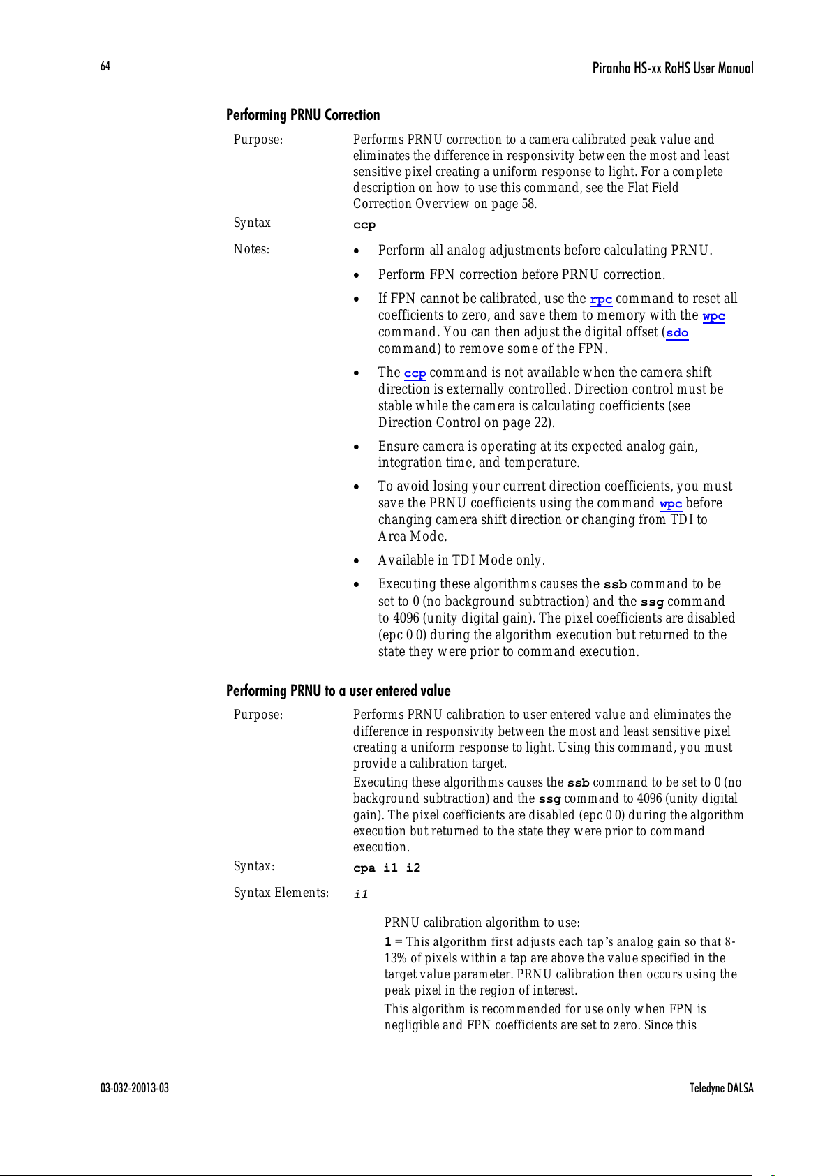
Piranha HS-xx RoHS User Manual
03-032-20013-03 Teledyne DALSA
64
Performing PRNU Correction
Purpose:
Performs PRNU correction to a camera calibrated peak value and
eliminates the difference in responsivity between the most and least
sensitive pixel creating a uniform response to light. For a complete
description on how to use this command, see the Flat Field
Correction Overview on page 58.
Syntax
ccp
Notes:
Perform all analog adjustments before calculating PRNU.
Perform FPN correction before PRNU correction.
If FPN cannot be calibrated, use the rpc command to reset all
coefficients to zero, and save them to memory with the wpc
command. You can then adjust the digital offset (sdo
command) to remove some of the FPN.
The ccp command is not available when the camera shift
direction is externally controlled. Direction control must be
stable while the camera is calculating coefficients (see
Direction Control on page 22).
Ensure camera is operating at its expected analog gain,
integration time, and temperature.
To avoid losing your current direction coefficients, you must
save the PRNU coefficients using the command wpc before
changing camera shift direction or changing from TDI to
Area Mode.
Available in TDI Mode only.
Executing these algorithms causes the ssb command to be
set to 0 (no background subtraction) and the ssg command
to 4096 (unity digital gain). The pixel coefficients are disabled
(epc 0 0) during the algorithm execution but returned to the
state they were prior to command execution.
Performing PRNU to a user entered value
Purpose:
Performs PRNU calibration to user entered value and eliminates the
difference in responsivity between the most and least sensitive pixel
creating a uniform response to light. Using this command, you must
provide a calibration target.
Executing these algorithms causes the ssb command to be set to 0 (no
background subtraction) and the ssg command to 4096 (unity digital
gain). The pixel coefficients are disabled (epc 0 0) during the algorithm
execution but returned to the state they w ere prior to command
execution.
Syntax:
cpa i1 i2
Syntax Elements:
i1
PRNU calibration algorithm to use:
1 = Th is algorith m first a d justs each tap ’s an alog gain so that 8 -
13% of pixels within a tap are above the value specified in the
target value parameter. PRNU calibration then occurs using the
peak pixel in the region of interest.
This algorithm is recommended for use only w hen FPN is
negligible and FPN coefficients are set to zero. Since this
All manuals and user guides at all-guides.com

Piranha HS-xx RoHS User Manual
Teledyne DALSA 03-032-20013-03
65
algorithm adjusts the analog gain, it also affects FPN. If FPN is
calibrated prior to running this algorithm, FPN will be
observable in dark conditions and an incorrect FPN value will be
used d uring PRNU calibration resulting in incorrect PRNU
coefficients.
2 = Calculates the PRNU coefficients using the entered target
value as shown below:
PRNU Coefficient =
Target
(AVG Pixel Value ) - (FPN + value)sdo
i
i
i
The calculation is performed for all sensor pixels but warnings
are only applied to pixels in the region of interest. This
algorithm is useful for achieving uniform output across multiple
cameras. Is is important that the target value (set with the next
parameter) is set to be at least equal to the highest pixel across all
cameras so that all pixels can reach the highest pixel value
during calibration.
3 = This algorithm includes an analog gain adjustment prior to
PRNU calibration. Analog gain is first adjusted so that the peak
pixel value in tap’s ROI is within 97 to 99% of the specified
target value. It then calculates the PRNU coefficients using the
target value as shown below:
PRNU Coefficient =
Target
(AVG Pixel Value ) - (FPN + value)sdo
i
i
i
The calculation is performed for all sensor pixels but warnings
are only applied to pixels in the region of interest. This
algorithm is useful for achieving uniform output across multiple
cameras.
This algorithm is useful for achieving uniform output across
multiple cameras by first adjusting analog gain and then
performing PRNU calibration. This algorithm is recommended
for use only when FPN is negligible and FPN coefficients are set
to zero. Since this algorithm adjusts the analog gain, it also
affects FPN. If FPN is calibrated prior to running this algorithm,
FPN will be observable in dark conditions and an incorrect FPN
value will be used during PRNU calibration resulting in
incorrect PRNU coefficients.
This algorithm is more robust and repeatable than algorithm 1
because it uses an average pixel value rather than a number
above target. However, this algorithm is slower.
4 = Calculates the PRNU coefficient in the same way as cpa 2
with the exception that this command only calculates PRNU for
pixels within the current Region of Interest (ROI).
i2
Peak target value in a range from 1024 to 4055DN. The target
value must be greater than the current peak output value.
Notes:
Perform all analog adjustments before calibrating PRNU.
This command performs the same function as the cpp
command but forces you to enter a target value.
Calibrate FPN before calibrating PRNU. If you are not
performing FPN calibration then issue the rpc (reset pixel
coefficients) command and set the sdo (set digital offset) value
All manuals and user guides at all-guides.com
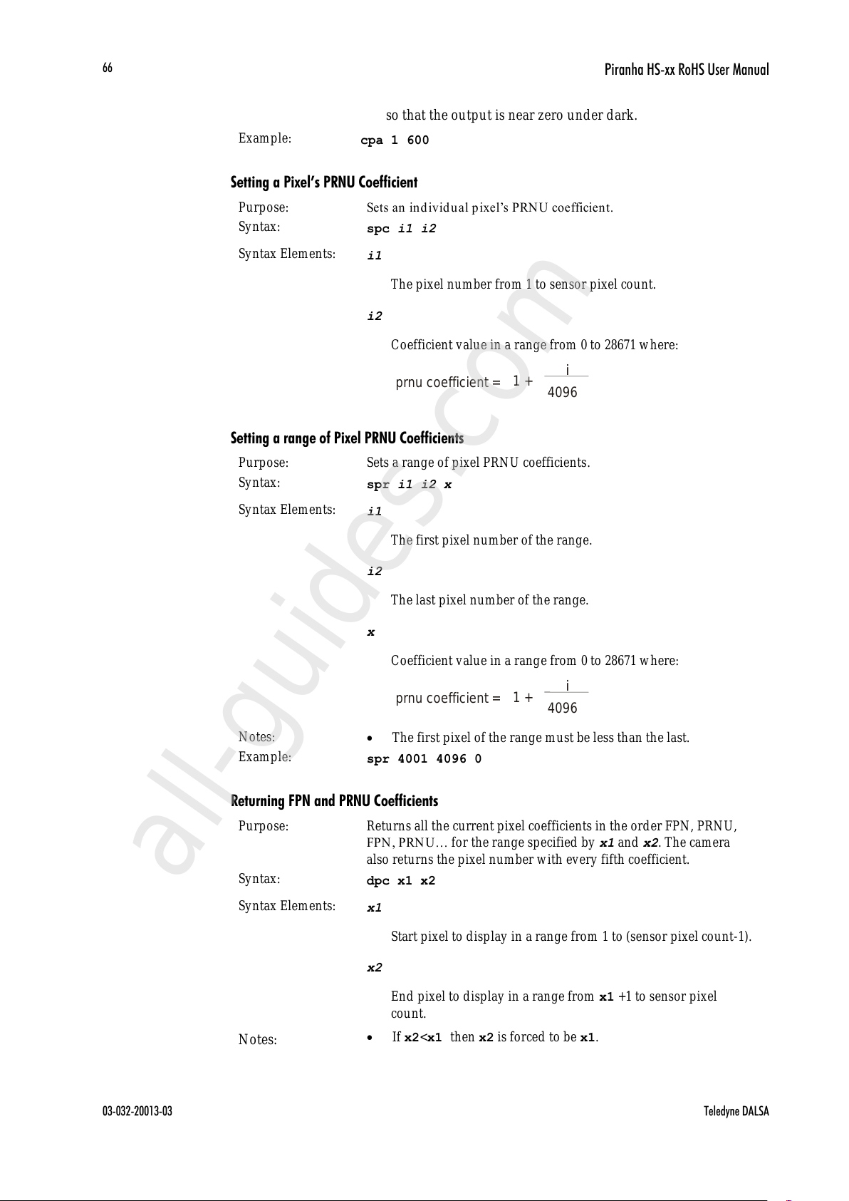
Piranha HS-xx RoHS User Manual
03-032-20013-03 Teledyne DALSA
66
so that the output is near zero under dark.
Example:
cpa 1 600
Setting a Pixel’s PRNU Coefficient
Purpose:
Sets an individual p ixel’s PRN U coefficient.
Syntax:
spc i1 i2
Syntax Elements:
i1
The pixel number from 1 to sensor pixel count.
i2
Coefficient value in a range from 0 to 28671 where:
Setting a range of Pixel PRNU Coefficients
Purpose:
Sets a range of pixel PRNU coefficients.
Syntax:
spr i1 i2 x
Syntax Elements:
i1
The first pixel number of the range.
i2
The last pixel number of the range.
x
Coefficient value in a range from 0 to 28671 where:
Notes:
The first pixel of the range must be less than the last.
Example:
spr 4001 4096 0
Returning FPN and PRNU Coefficients
Purpose:
Returns all the current pixel coefficients in the order FPN, PRNU,
FPN , PRNU… for the range specified by x1 and x2. The camera
also returns the pixel number with every fifth coefficient.
Syntax:
dpc x1 x2
Syntax Elements:
x1
Start pixel to display in a range from 1 to (sensor pixel count-1).
x2
End pixel to display in a range from x1 +1 to sensor pixel
count.
Notes:
If x2<x1 then x2 is forced to be x1.
prnu coefficient =
i
4096
1 +
prnu coefficient =
i
4096
1 +
All manuals and user guides at all-guides.com
all-guides.com
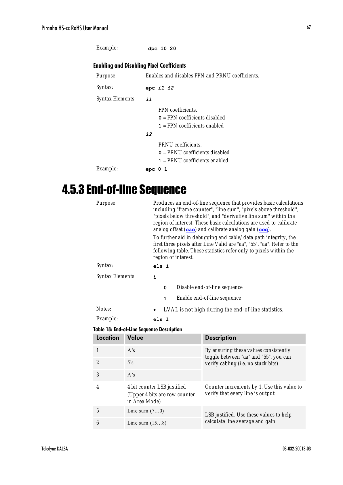
Piranha HS-xx RoHS User Manual
Teledyne DALSA 03-032-20013-03
67
Example:
dpc 10 20
Enabling and Disabling Pixel Coefficients
Purpose:
Enables and disables FPN and PRNU coefficients.
Syntax:
epc i1 i2
Syntax Elements:
i1
FPN coefficients.
0 = FPN coefficients disabled
1 = FPN coefficients enabled
i2
PRNU coefficients.
0 = PRNU coefficients disabled
1 = PRNU coefficients enabled
Example:
epc 0 1
4.5.3 End-of-line Sequence
Purpose:
Produces an end-of-line sequence that provides basic calculations
including "frame counter", "line sum", "pixels above threshold",
"pixels below threshold", and "derivative line sum" within the
region of interest. These basic calculations are used to calibrate
analog offset (cao) and calibrate analog gain (ccg).
To further aid in debugging and cable/ data path integrity, the
first three pixels after Line Valid are "aa", "55", "aa". Refer to the
following table. These statistics refer only to pixels within the
region of interest.
Syntax:
els i
Syntax Elements:
i 0
Disable end-of-line sequence
1 Enable end-of-line sequence
Notes:
LVAL is not high during the end-of-line statistics.
Example:
els 1
Table 18: End-of-Line Sequence Description
Location
Value
Description
1
A’s
By ensuring these values consistently
toggle between "aa" and "55", you can
verify cabling (i.e. no stuck bits)
2
5’s 3 A’s
4
4 bit counter LSB justified
(Upper 4 bits are row counter
in Area Mode)
Counter increments by 1. Use this value to
verify that every line is output
5
Line su m (7…0)
LSB justified. Use these values to help
calculate line average and gain
6
Line su m (15…8)
All manuals and user guides at all-guides.com

Piranha HS-xx RoHS User Manual
03-032-20013-03 Teledyne DALSA
68
Location
Value
Description
7
Line su m (23…16)
8
Line su m (31…24)
9
Line su m (39…32)
10
Pixels above threshold (7…0)
Monitor these values (either above or
below threshold) and adjust camera
digital gain and background subtract to
maximize scene contrast. This provides a
basis for automatic gain control (AGC)
11
Pixels above threshold
(15…8)
12
Pixels above threshold
(23…16)
13
Pixels below th resh old (7…0)
14
Pixels below th resh old (15…8)
15
Pixels below threshold
(23…16)
16
Differential line sum (7..0)
Use these values to focus the camera.
Generally, the greater the sum the greater
the image contrast and better the focus.
17
Differential line su m (15…8)
18
Differential line su m (23…16)
19
Differential line su m (31…24)
20
Differential line su m (39…32)
Setting Thresholds
Setting an Upper Threshold
Purpose:
Sets the upper threshold limit to report in the end -of-line
sequence.
Syntax:
sut i
Syntax Elements:
i
Upper threshold limit in range from 0 to 4095.
Notes:
LVAL is not high during the end-of-line statistics.
Related Commands:
els, slt
Example:
sut 1024
All manuals and user guides at all-guides.com

Piranha HS-xx RoHS User Manual
Teledyne DALSA 03-032-20013-03
69
Setting a Lower Threshold
Purpose:
Sets the lower threshold limit to report in the end -of-line
sequence.
Syntax:
slt i
Syntax Elements:
i
Upper threshold limit in range from 0 to 4095.
Notes:
LVAL is not high during the end-of-line statistics.
Related Commands:
els, sut
Example:
slt 1024
4.6 Saving and Restoring Settings
4.6.1 Saving and Restoring Factory and User Settings
Figure 32: Saving and Restoring Overview
Factory
Settings
Current
Session
wus wpc,wfc,
rus lpc,
rfs
User
Settings
Factory Settings
You can restore the original factory settings, including the factory calibrated pixel
coefficient set, at any time using the command rfs.
User Settings
There are two main sets of user settings: Area Mode user settings and TDI Mode user
settings. After issuing the user settings save command, wus, settings are saved depending
on which mode the camera is operating in when the command is issued. Also, when
operating in TDI Mode, analog gain and offset, digital gain and offset, and background
subtract values are saved as distinct values for Forward and Reverse directions. In other
words, you can program the camera to operate with an analog gain value of +5db in
Forward direction and an analog gain value of +3db in Reverse direction. Forward and
Reverse direction settings are saved simultaneously with the wus command. Note that
when you switch directions, the settings saved for that direction are automatically loaded.
All manuals and user guides at all-guides.com
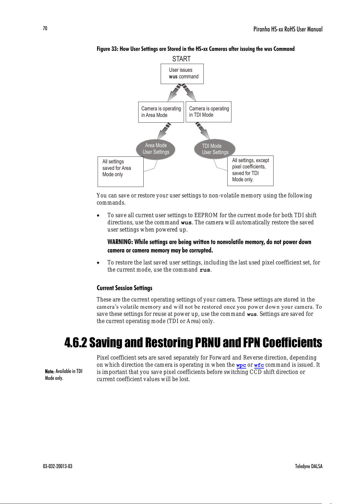
Piranha HS-xx RoHS User Manual
03-032-20013-03 Teledyne DALSA
70
Figure 33: How User Settings are Stored in the HS-xx Cameras after issuing the wus Command
Area Mode
User Settings
All settings
saved for Area
Mode only
Camera is operating
in TDI Mode
Camera is operating
in Area Mode
User issues
command
wus
START
TDI Mode
User Settings
All settings, except
pixel coefficients,
saved for TDI
Mode only.
You can save or restore your user settings to non -volatile memory using the following
commands.
To save all current user settings to EEPROM for the current mode for both TDI shift
directions, use the command wus. The camera will automatically restore the saved
user settings when powered up.
WARNING: While settings are being written to nonvolatile memory, do not power down
camera or camera memory may be corrupted.
To restore the last saved user settings, including the last used pixel coefficient set, for
the current mode, use the command rus.
Current Session Settings
These are the current operating settings of your camera. These settings are stored in the
cam era’s volatile m emory and will not be restored on ce y ou pow er dow n you r cam era. To
save these settings for reuse at power up, use the command wus. Settings are saved for
the current operating mode (TDI or Area) only.
4.6.2 Saving and Restoring PRNU and FPN Coefficients
Pixel coefficient sets are saved separately for Forward and Reverse direction, depending
on which direction the camera is operating in when the wpc or wfc command is issued. It
is important that you save pixel coefficients before switching CCD shift direction or
current coefficient values will be lost.
Note: Available in TDI
Mode only.
All manuals and user guides at all-guides.com

Piranha HS-xx RoHS User Manual
Teledyne DALSA 03-032-20013-03
71
Figure 34: How Pixel Coefficients are saved in the HS-xx Cameras after issuing the wpc or wfc Command
Coefficients saved
for forward direction
only
Camera is operating
in reverse direction
Camera is operating
in forward direction
User issues or command.
Note: Camera must be operating in TDI Mode
wpc wfc
START
Coefficients saved
for reverse direction
only.
Saving the Current PRNU Coefficients
Purpose:
Saves the current PRNU coefficients for the current direction.
Syntax:
wpc i
Syntax Elements:
i
PRNU coefficients set to save.
1 = Coefficient set one
2 = Coefficient set tw o
3 = Coefficient set three
4 = Coefficient set four
Notes:
Available in TDI mode only.
Available only when operating the camera in internal
direction contol (scd 0 or 1)
Example:
wpc 2
Saving the Current FPN Coefficients
Purpose:
Saves the current FPN coefficients for the current direction.
Syntax:
wfc i
Syntax Elements:
i
FPN coefficients set to save.
1 = Coefficient set one
2 = Coefficient set tw o
3 = Coefficient set three
4 = Coefficient set four
Notes:
Available in TDI mode only.
Available only when operating the camera in internal
direction contol (scd 0 or 1)
Example:
wfc 2
All manuals and user guides at all-guides.com
all-guides.com

Piranha HS-xx RoHS User Manual
03-032-20013-03 Teledyne DALSA
72
Loading a Saved Set of Coefficients
Purpose:
Loads a saved set of pixel coefficients for the current direction. A
factory calibrated set of coefficients is available.
Syntax:
lpc i
Syntax Elements:
i
FPN coefficients set to save.
0 = Factory calibrated pixel coefficients.
1 = Coefficient set one
2 = Coefficient set tw o
3 = Coefficient set three
4 = Coefficient set four
Notes:
Available in TDI mode only.
Available only when operating the camera in internal
direction contol (scd 0 or 1). When operating in external
direction control, you must switch to internal direction
control, load the coefficient set, and then return to external
direction contol.
Example:
lpc 0
Resetting the Current Pixel Coefficients
Purpose:
Resets the current pixel coefficients to zero. This command does not
reset saved coefficients.
Syntax:
rpc
Notes:
The digital offset is not reset.
4.6.3 Rebooting the Camera
The command rc reboots the camera. The camera starts up with the last saved settings
and the baud rate used before reboot. Previously saved pixel coefficients are also restored.
All manuals and user guides at all-guides.com

Piranha HS-xx RoHS User Manual
Teledyne DALSA 03-032-20013-03
73
4.7 Diagnostics
4.7.1 Generating a Test Pattern
Purpose:
Generates a test pattern to aid in system debugging. The test
patterns are useful for verifying proper timing and connections
between the camera and the frame grabber. The following tables
show each available test pattern.
Syntax:
svm i
Syntax Elements:
i 0
Video.
1 12 bit test pattern 1 (ramp)
2 8 bit test pattern 2 (step)
Notes:
When returning to video (svm 0) after viewing a test pattern,
the camera restores the saved user settings for digital offset
(sdo), enable pixel coefficients (epc), set subtract background
(ssb), and set system digital gain (ssg).
The follow ing diagrams show 12-bit pixel values. When
operating in 8-bit mode, pixel values will be 1/ 16th of pixel
values in the diagram.
Example:
svm 2
Table 19: 4k Test Patterns
4k Camera
Operating
Mode
Test Pattern
TDI Mode
Forward,
smm 0, svm
1
1
0
2
3
4
0
9
5
1
0
2
4
2
0
4
7
2
0
4
8
3
0
7
1
3
0
7
2
0
TDI Mode
Reverse, smm
0, svm 1
1
0
2
3
4
0
9
5
1
0
2
4
2
0
4
7
2
0
4
8
3
0
7
1
3
0
7
2
0
TDI Mode
Forward,
smm 1, svm
1
1
0
2
3
4
0
9
5
1
0
2
4
2
0
4
7
2
0
4
8
3
0
7
1
3
0
7
2
0
TDI Mode
Reverse, smm
1, svm 1
1
0
2
3
4
0
9
5
1
0
2
4
2
0
4
7
2
0
4
8
3
0
7
1
3
0
7
2
0
Area Mode
Forward,
smm 0, svm
1
1
0
3
0
6
1
0
3
1
2
0
5
4
2
0
5
5
3
0
7
8
3
0
7
9
7
All manuals and user guides at all-guides.com

Piranha HS-xx RoHS User Manual
03-032-20013-03 Teledyne DALSA
74
Area Mode
Reverse, smm
0, svm 1
1
0
3
0
7
1
0
3
1
2
0
5
4
2
0
5
5
3
0
7
8
3
0
7
8
7
Area Mode
Forward,
smm1, svm
1
1
0
3
0
6
1
0
3
1
2
0
5
4
2
0
5
5
3
0
7
8
3
0
7
9
7
Area Mode
Reverse,
smm1, svm
2
1
0
0
8
2
0
3
2
3
0
5
6
4
0
8
0
TDI or Area
Mode, smm
0, svm 2
1
0
0
8
2
0
3
2
3
0
5
6
4
0
8
0
Table 20: 8k Test Patterns
8k
Camera
Operating
Mode
Test Pattern
TDI Mode
Forward,
smm 0, svm
1
4
0
9
5
3
8
5
6
3
6
1
7
3
3
7
8
2
9
0
0
2
6
6
1
2
4
2
2
1
9
4
4
1
7
0
5
1
4
6
6
3
1
3
9
9
8
8
2
1
8
3
5
1
1
1
2
2
7
7
4
9
0
2
3
8
4
7
7
7
1
6
9
5
5
1
1
9
4
1
4
3
3
1
6
7
2
1
9
1
1
2
1
5
0
2
3
8
9
2
6
2
8
2
8
6
7
3
1
0
6
3
3
4
5
3
5
8
4
TDI Mode
Forward,
smm 1, svm
1
4
0
9
5
3
8
5
6
3
6
1
7
3
3
7
8
2
9
0
0
2
6
6
1
2
4
2
2
1
9
4
4
1
7
0
5
1
4
6
6
3
1
3
9
9
8
8
2
1
8
3
5
1
1
1
2
2
7
7
4
9
0
2
3
8
4
7
7
7
1
6
9
5
5
1
1
9
4
1
4
3
3
1
6
7
2
1
9
1
1
2
1
5
0
2
3
8
9
2
6
2
8
2
8
6
7
3
1
0
6
3
3
4
5
3
5
8
4
TDI Mode
Reverse, smm
1, svm 1
4
0
9
5
3
8
5
6
3
6
1
7
3
3
7
8
2
9
0
0
2
6
6
1
2
4
2
2
1
9
4
4
1
7
0
5
1
4
6
6
3
1
3
9
9
8
8
2
1
8
3
5
1
1
1
2
2
7
7
4
9
0
2
3
8
4
7
7
7
1
6
9
5
5
1
1
9
4
1
4
3
3
1
6
7
2
1
9
1
1
2
1
5
0
2
3
8
9
2
6
2
8
2
8
6
7
3
1
0
6
3
3
4
5
3
5
8
4
Area Mode
Forward,
smm 0, svm
1
6
3
6
2
4
3
3
8
5
2
9
0
7
2
6
6
8
2
4
2
9
1
9
5
1
1
7
1
2
3
1
4
6
2
1
9
0
5
1
7
1
2
3
4
7
5
6
7
2
4
5
4
8
4
7
3
0
1
2
0
1
1
4
4
0
1
6
7
9
1
9
1
8
2
1
5
7
2
3
9
6
2
6
3
5
2
8
7
4
3
1
1
3
3
3
5
2
3
5
9
1
Area Mode
Reverse, smm
0, svm 1
6
3
6
2
4
3
3
8
5
2
9
0
7
2
6
6
8
2
4
2
9
1
9
5
1
1
7
1
2
1
4
7
3
3
1
4
6
9
9
6
2
1
9
0
5
1
8
1
2
3
4
7
5
7
7
2
4
6
9
6
2
1
2
0
1
1
4
4
0
1
6
7
9
1
9
1
8
2
1
5
7
2
3
9
6
2
6
3
5
3
1
1
3
3
3
5
2
3
5
9
1
Area Mode
Forward,
smm 1, svm
1
6
3
8
6
3
3
6
2
4
3
3
8
5
2
9
0
7
2
6
6
8
2
4
2
9
1
9
5
1
1
4
7
3
3
1
4
6
9
9
6
2
1
9
0
5
1
8
1
2
3
4
7
5
7
7
2
4
6
7
3
0
9
6
2
1
2
0
1
1
4
4
0
1
9
1
8
2
1
5
7
2
3
9
6
2
6
3
5
2
8
7
4
3
3
5
2
3
5
9
1
All manuals and user guides at all-guides.com
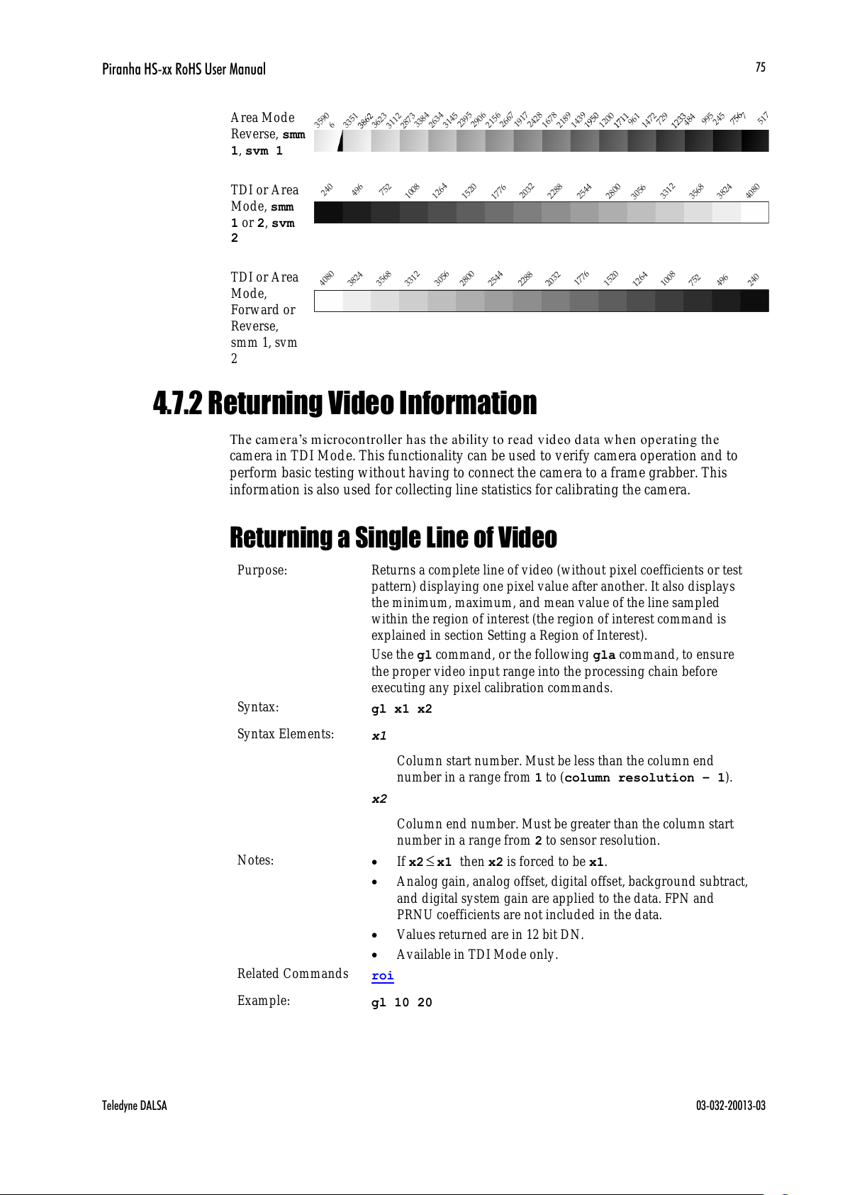
Piranha HS-xx RoHS User Manual
Teledyne DALSA 03-032-20013-03
75
Area Mode
Reverse, smm
1, svm 1
6
3
6
2
3
3
3
8
4
2
9
0
6
26
6
7
2
4
2
8
1
4
7
2
3
1
4
5
9
9
5
2
1
8
9
5
1
7
7
2
4
5
4
8
4
7
2
9
9
6
1
1
2
0
0
1
4
3
9
1
67
8
1
9
1
7
2
1
5
6
2
3
9
5
2
6
3
4
2
8
7
3
3
1
1
2
3
3
5
1
3
5
9
0
TDI or Area
Mode, smm
1 or 2, svm
2
2
4
0
4
9
6
7
5
2
1
2
6
4
1
5
20
1
7
7
6
2
0
3
2
2
2
8
8
2
5
4
4
2
8
0
0
3
0
5
6
3
3
1
2
3
5
6
8
3
8
2
4
4
0
8
0
1
0
0
8
TDI or Area
Mode,
Forward or
Reverse,
smm 1, svm
2
2
4
0
4
9
6
7
5
2
1
2
6
4
1
5
2
0
1
7
7
6
2
0
3
2
2
2
8
8
2
5
4
4
2
8
0
0
3
0
5
6
3
3
1
2
3
5
6
8
3
8
2
4
4
0
8
0
1
0
0
8
4.7.2 Returning Video Information
The cam era’s microcon troller has the ability to read video d ata w hen op eratin g th e
camera in TDI Mode. This functionality can be used to verify camera operation and to
perform basic testing without having to connect the camera to a frame grabber. This
information is also used for collecting line statistics for calibrating the camera.
Returning a Single Line of Video
Purpose:
Returns a complete line of video (without pixel coefficients or test
pattern) displaying one pixel value after another. It also displays
the minimum, maximum, and mean value of the line sampled
within the region of interest (the region of interest command is
explained in section Setting a Region of Interest).
Use the gl command, or the following gla command, to ensure
the proper video input range into the processing chain before
executing any pixel calibration commands.
Syntax:
gl x1 x2
Syntax Elements:
x1
Column start number. Must be less than the column end
number in a range from 1 to (column resolution – 1).
x2
Column end number. Must be greater than the column start
number in a range from 2 to sensor resolution.
Notes:
If x2x1 then x2 is forced to be x1.
Analog gain, analog offset, digital offset, background subtract,
and digital system gain are applied to the data. FPN and
PRNU coefficients are not included in the data.
Values returned are in 12 bit DN.
Available in TDI Mode only.
Related Commands
roi
Example:
gl 10 20
All manuals and user guides at all-guides.com

Piranha HS-xx RoHS User Manual
03-032-20013-03 Teledyne DALSA
76
Returning Averaged Lines of Video
Setting the Number of Lines to Sample
Purpose:
Sets the number of lines to sample when using the gla command
or for pixel coefficient calculations.
Syntax:
css i
Syntax Elements:
i
Number of lines to sample. Allowable values are 256, 512, or
1024 (factory setting).
Notes:
To return the current setting, use the gcp command.
Related Commands:
gla
Example:
css 1024
Returning the Average of Multiple Lines of Video
Purpose:
Returns the average for multiple lines of video data (without pixel
coefficients or test pattern). The number of lines to sample is set
and adjusted by the css command. The camera displays the Min.,
Max., and Mean statistics for the pixels in the region of interest (the
region of interest command is explained in section Setting a Region
of Interest).
Syntax:
gla x1 x2
Syntax Elements:
x1
Column start number. Must be less than the column end
number in a range from 1 to (column resolution – 1).
x2
Column end number. Must be greater than the column start
number in a range from 2 to column resolution.
Notes:
If x2x1 then x2 is forced to be x1.
Analog gain, analog offset, digital offset, background subtract,
and digital system gain are applied to the data. FPN and
PRNU coefficients are not included in the data.
Values returned are in 12 bit DN.
Available in TDI Mode only.
Related Commands:
css, roi
Example:
gla 10 20
4.7.3 Temperature Measurement
The temperature of the camera can be determined by using the vt command. This
command will return the internal chip temperature in degrees Celsius. For proper
operation, this value should not exceed 75°C.
Note: If the camera reaches 75°C, the camera will shutdown and the LED will flash red.
If this occurs, the camera must be rebooted using the command, rc or can be powered
down manually. You will have to correct the temperature problem or the camera will
shutdown again.
All manuals and user guides at all-guides.com
all-guides.com
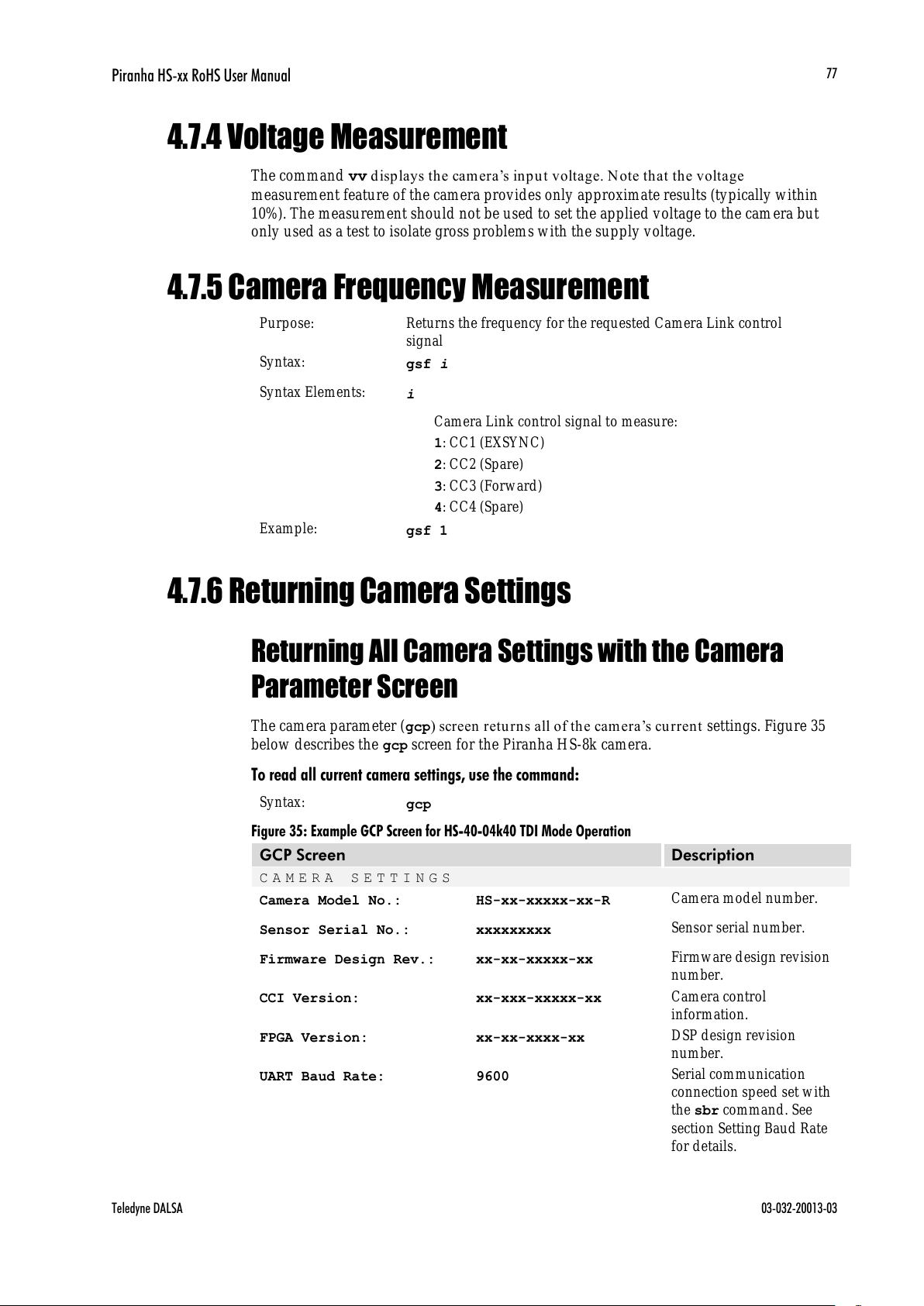
Piranha HS-xx RoHS User Manual
Teledyne DALSA 03-032-20013-03
77
4.7.4 Voltage Measurement
The command vv d isp la ys th e cam era’s in p u t voltage. Note that the voltage
measurement feature of the camera provides only approximate results (typically within
10%). The measurement should not be used to set the applied voltage to the camera but
only used as a test to isolate gross problems with the supply voltage.
4.7.5 Camera Frequency Measurement
Purpose:
Returns the frequency for the requested Camera Link control
signal
Syntax:
gsf i
Syntax Elements:
i
Camera Link control signal to measure:
1: CC1 (EXSYNC)
2: CC2 (Spare)
3: CC3 (Forward)
4: CC4 (Spare)
Example:
gsf 1
4.7.6 Returning Camera Settings
Returning All Camera Settings with the Camera
Parameter Screen
The camera parameter (gcp) screen retu rns all of the cam era’s cu rrent settings. Figure 35
below describes the gcp screen for the Piranha HS-8k camera.
To read all current camera settings, use the command:
Syntax:
gcp
Figure 35: Example GCP Screen for HS-40-04k40 TDI Mode Operation
GCP Screen
Description
CAMERA SETTINGS
Camera Model No.:
HS-xx-xxxxx-xx-R
Camera model number.
Sensor Serial No.:
xxxxxxxxx
Sensor serial number.
Firmware Design Rev.:
xx-xx-xxxxx-xx
Firmware design revision
number.
CCI Version:
xx-xxx-xxxxx-xx
Camera control
information.
FPGA Version:
xx-xx-xxxx-xx
DSP design revision
number.
UART Baud Rate:
9600
Serial communication
connection speed set with
the sbr command. See
section Setting Baud Rate
for details.
All manuals and user guides at all-guides.com
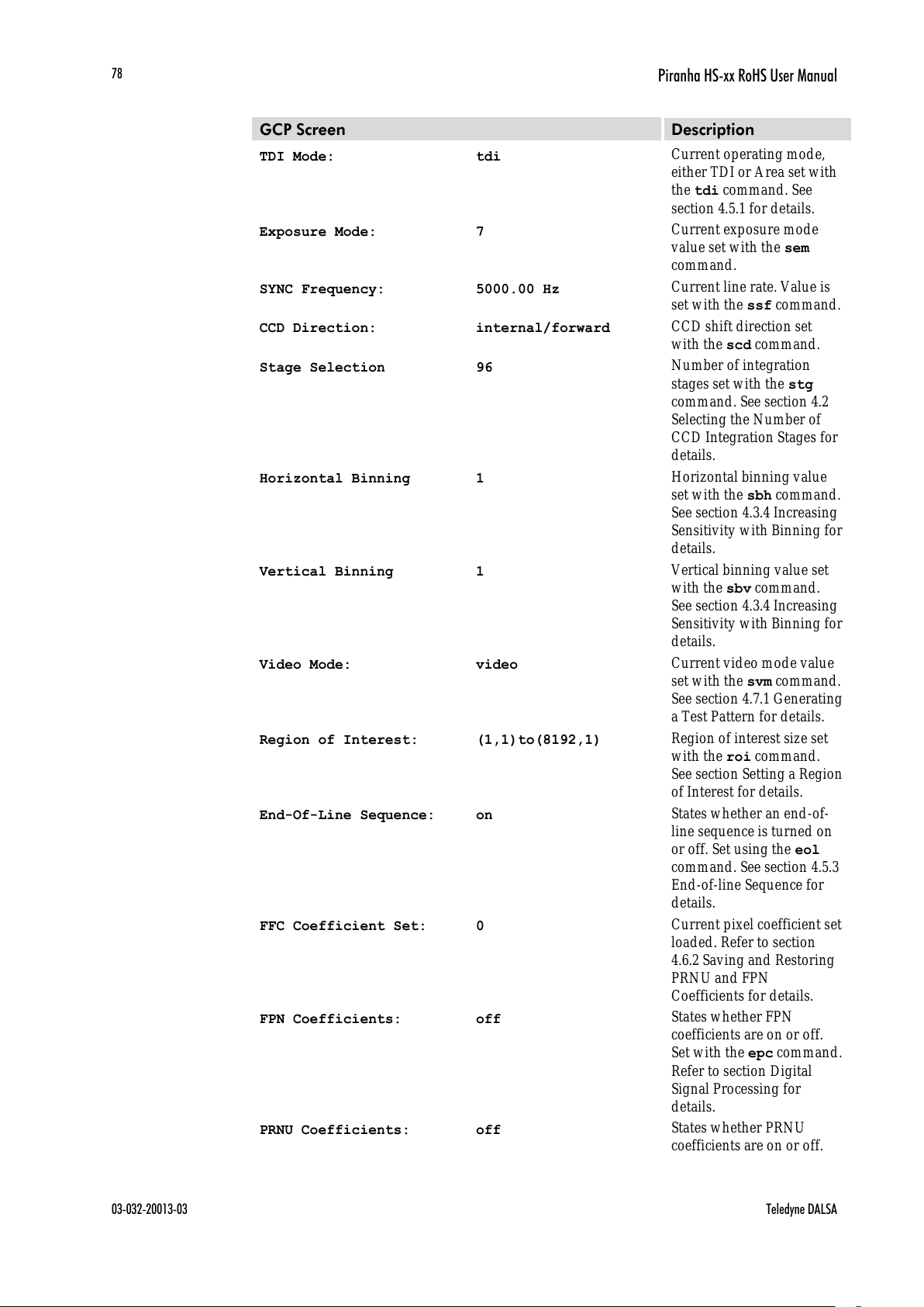
Piranha HS-xx RoHS User Manual
03-032-20013-03 Teledyne DALSA
78
GCP Screen
Description
TDI Mode:
tdi
Current operating mode,
either TDI or Area set with
the tdi command. See
section 4.5.1 for details.
Exposure Mode:
7
Current exposure mode
value set with the sem
command.
SYNC Frequency:
5000.00 Hz
Current line rate. Value is
set with the ssf command.
CCD Direction:
internal/forward
CCD shift direction set
with the scd command.
Stage Selection
96
Number of integration
stages set with the stg
command. See section 4.2
Selecting the Number of
CCD Integration Stages for
details.
Horizontal Binning
1
Horizontal binning value
set with the sbh command.
See section 4.3.4 Increasing
Sensitivity with Binning for
details.
Vertical Binning
1
Vertical binning value set
with the sbv command.
See section 4.3.4 Increasing
Sensitivity with Binning for
details.
Video Mode:
video
Current video mode value
set with the svm command.
See section 4.7.1 Generating
a Test Pattern for details.
Region of Interest:
(1,1)to(8192,1)
Region of interest size set
with the roi command.
See section Setting a Region
of Interest for details.
End-Of-Line Sequence:
on
States whether an end-of-
line sequence is turned on
or off. Set using the eol
command. See section 4.5.3
End-of-line Sequence for
details.
FFC Coefficient Set:
0
Current pixel coefficient set
loaded. Refer to section
4.6.2 Saving and Restoring
PRNU and FPN
Coefficients for details.
FPN Coefficients:
off
States whether FPN
coefficients are on or off.
Set with the epc command.
Refer to section Digital
Signal Processing for
details.
PRNU Coefficients:
off
States whether PRNU
coefficients are on or off.
All manuals and user guides at all-guides.com
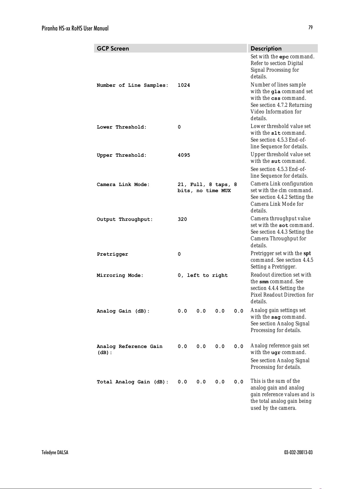
Piranha HS-xx RoHS User Manual
Teledyne DALSA 03-032-20013-03
79
GCP Screen
Description
Set with the epc command.
Refer to section Digital
Signal Processing for
details.
Number of Line Samples:
1024
Number of lines sample
with the gla command set
with the css command.
See section 4.7.2 Returning
Video Information for
details.
Lower Threshold:
0
Lower threshold value set
with the slt command.
See section 4.5.3 End-of-
line Sequence for details.
Upper Threshold:
4095
Upper threshold value set
with the sut command.
See section 4.5.3 End-of-
line Sequence for details.
Camera Link Mode:
21, Full, 8 taps, 8
bits, no time MUX
Camera Link configuration
set with the clm command.
See section 4.4.2 Setting the
Camera Link Mode for
details.
Output Throughput:
320
Camera throughput value
set with the sot command.
See section 4.4.3 Setting the
Camera Throughput for
details.
Pretrigger
0
Pretrigger set with the spt
command. See section 4.4.5
Setting a Pretrigger.
Mirroring Mode:
0, left to right
Readout direction set with
the smm command. See
section 4.4.4 Setting the
Pixel Readout Direction for
details.
Analog Gain (dB):
0.0 0.0 0.0 0.0
Analog gain settings set
with the sag command.
See section Analog Signal
Processing for details.
Analog Reference Gain
(dB):
0.0 0.0 0.0 0.0
Analog reference gain set
with the ugr command.
See section Analog Signal
Processing for details.
Total Analog Gain (dB):
0.0 0.0 0.0 0.0
This is the sum of the
analog gain and analog
gain reference values and is
the total analog gain being
used by the camera.
All manuals and user guides at all-guides.com

Piranha HS-xx RoHS User Manual
03-032-20013-03 Teledyne DALSA
80
GCP Screen
Description
Analog Offset:
80 80 80 80
Analog offset settings set
with the sao command.
See section Analog Signal
Processing for details.
Digital Offset:
80 80 80 80
Digital offset settings set
with the sdo command.
See section Digital Signal
Processing for details.
Background Subtract:
0 0 0 0
Background subtract
settings set with the ssb
command. See section
Digital Signal Processing
for details.
System Gain:
4096 4096 4096
4096
Digital gain settings set
with the ssg command.
See section Digital Signal
Processing for details.
Returning Camera Settings with Get Commands
You can also return individual camera settings by insertin g a ― get” in front of the
command that you want to query. If the command has a tap or pixel number parameter,
you must also insert the tap number or pixel number that you want to query. Refer to
Table 21 below for a list of available commands. To view a help screen listing the
following get commands, use the command gh.
Table 21: Get Commands
Syntax
Parameters
Description
get cao
t
Returns the analog offset for the tap indicated
t = tap selection, either 1 to number of CCD taps, or
0 for all taps
get ccf
x1 x2
Returns the FPN pixel coefficients for the pixel range
indicated.
x1 = Pixel start number
x2= Pixel end number
get ccp
x1 x2
Returns the PRNU pixel coefficients for the pixel range
indicated.
x1 = Pixel start number
x2= Pixel end number
get clm
Returns the current Camera Link mode.
get css
Returns the number of line samples averaged for pixel
coefficient calculations or for output of gla command.
get dpc
X1 X2
Returns the pixel coefficients in the order FPN, PRNU,
FPN , PRNU, …
x1 = Pixel start number
x2= Pixel end number
in a range from 1 to sensor pixel count.
All manuals and user guides at all-guides.com

Piranha HS-xx RoHS User Manual
Teledyne DALSA 03-032-20013-03
81
Syntax
Parameters
Description
get els
Returns whether the end-of-line statistics are turned off or
on.
0: Off
1: On
get epc
Returns whether pixel coefficients are enabled or
disabled.
The first parameter returns the FPN coefficients setting
where:
0 = FPN coefficients disabled
1 = FPN coefficients enabled
The second parameter returns the PRNU coefficients
setting where:
0 = PRNU coefficients disabled
1 = PRNU coefficients enabled
get gcm
Retur ns the cam er a’s m od el nu m ber
get gcs
Retur ns the cam er a’s serial n umber
get gcv
Retur ns the cam er a’s softw are version .
get gfc
x
Returns the FPN pixel coefficient for the pixel indicated.
get gl
x1 x2
Returns pixel values for the pixel range specified.
get gla
x1 x2
Returns the average of the pixel range indicated.
get gpc
x
Returns PRNU coefficient.
x = pixel number to read in a range from 1 – sensor pixel
count.
get gsf
i
Returns the frequency of the Camera Link control signal
indicated, either 1, 2, 3, or 4.
get h
Returns the onscreen help menu.
get lpc
Returns the current coefficient set number.
get rc
get rfs
Returns whether factory settings have been saved. The
camera always returns 1 (factory settings have been
saved).
get roi
Returns the current region of interest.
get rus
Returns whether user settings have been saved.
0 = No user settings saved
1 = User settings have been saved
get sag
t
Returns the analog gain in d B for the tap indicated
t = Tap value. 0 for all taps or 1-number of CCD taps
for individual tap selection.
get sao
t
Returns the analog offset for the tap indicated.
t = 0 for all taps or 1 to number of CCD taps for
individual tap selection.
get sbh
Returns the horizontal binning value.
get sbr
Returns the speed of camera serial communication port.
get sbv
Returns the vertical binning value.
All manuals and user guides at all-guides.com
all-guides.com

Piranha HS-xx RoHS User Manual
03-032-20013-03 Teledyne DALSA
82
Syntax
Parameters
Description
get scd
Returns the CCD shift direction where:
0 = Forward TDI shift direction.
1 = Reverse TDI shift direction.
2 = Externally controlled direction control via Camera
Link control CC3.
get sdo
t
Returns the digital offset value in DN for the tap
indicated.
t = Tap value. 0 for all taps or 1-number of CCD taps
for individual tap selection.
get sem
Returns the current exposure mode:
3 = External SYNC, maximum exposure time
7 = Internal programmable SYNC, maximum exposure
time. Factory setting.
get sfc
x
Returns the FPN coefficient for the pixel number idicated.
x =pixel number within the range 1 to sensor pixel
count.
get sfr
xx
Returns a range of pixel FPN coefficients
x1=first pixel number of the range.
x2=last pixel number of the range
i=coefficient value in a range from 0 to 2048.
get slt
Returns the current lower threshold value.
get smm
Retur ns the cam er a’s m irror m od e:
0: Pixels readout left to right (1 to 4096 or 8192)
1: Pixels readout right to left (8092 or 4096 to 1)
get sot
Returns the Camera Link strobe rate.
get spc
x
Returns the PRNU coefficient for the specified pixel
number.
x=pixel number within the range 1 to sensor pixel
count.
get spr
xx
Returns a range of pixel PRNU coefficients
i1=first pixel number of the range
i2=last pixel number of the range
x=coefficient value in a range from 0 to 28671.
get spt
Returns the current pretrigger setting.
get ssb
t
Returns the current background subtract value.
t = Tap value. 0 for all taps or 1 to number of CCD
taps for individual tap selection.
get ssf
Returns the current line/ frame rate in Hz.
get ssg
t
Returns the current digital gain setting.
t = tap selection, either 1 to number of CCD taps, or
0 for all taps
get stg
Returns the current number of CCD integration stages.
get sut
Returns the current uppder threshold value.
All manuals and user guides at all-guides.com
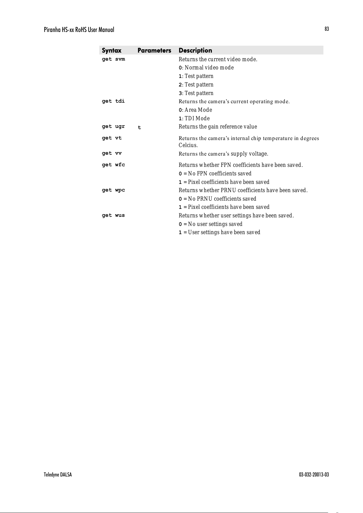
Piranha HS-xx RoHS User Manual
Teledyne DALSA 03-032-20013-03
83
Syntax
Parameters
Description
get svm
Returns the current video mode.
0: Normal video mode
1: Test pattern
2: Test pattern
3: Test pattern
get tdi
Retur ns the cam er a’s cu rrent op er ating m ode.
0: Area Mode
1: TDI Mode
get ugr
t
Returns the gain reference value
get vt
Retur ns the cam er a’s in tern al chip tem p erature in degrees
Celcius.
get vv
Retur ns the cam er a’s supply voltage.
get wfc
Returns whether FPN coefficients have been saved.
0 = No FPN coefficients saved
1 = Pixel coefficients have been saved
get wpc
Returns whether PRNU coefficients have been saved.
0 = No PRNU coefficients saved
1 = Pixel coefficients have been saved
get wus
Returns whether user settings have been saved.
0 = No user settings saved
1 = User settings have been saved
All manuals and user guides at all-guides.com

Piranha HS-xx RoHS User Manual
03-032-20013-03 Teledyne DALSA
84
All manuals and user guides at all-guides.com

Piranha HS-xx RoHS User Manual
Teledyne DALSA 03-032-20013-03
85
Appendix A
Error Handling and
Command List
Error Handling
The following table lists warning and error messages and provides a description and
possible cause. Warning messages are returned when the camera cannot meet the full
value of the request; error messages are returned when the camera is u nable to complete
the request.
Table 22: Warning and Error Messages
Warning Messages
Camera Response
Comment
OK>
Camera executed command
Warning 01: Outside of specification>
Parameter accepted was outside of specified
operating range (e.g. gain greater than ±10 dB of
factory setting, or SSF below specification).
Warning 02: Clipped to min>
Parameter was clipped to the current operating
range. Use GCP or GET to see value used.
Warning 03: Clipped to max>
Parameter was clipped to the current operating
range. Use GCP or GET to see value used.
Warning 04: Related parameters
adjusted>
Internal operating condition is adjusted to
accommodate the entered command. E.g.
requesting exposure time longer than line time
automatically adjusts the line time to meet the
exposure time requirement.
Warning 07: Coefficient may be
inaccurate A/ D clipping has occurred>
In the region of interest (ROI) greater than 6.251%
single or 1% of averaged pixel values were zero or
saturated.
Warning 08: Greater than 1% of
coefficients have been clipped
Greater than 1% of FPN or PRNU coefficients have
been calculated to be greater than the maximum
allowable and so were clipped.
Warning 09: Internal line rate
inconsistent with read out time>
Changing this param eter (e.g. vertical binning) has
changed read out time and that is greater than the
internal SYNC
All manuals and user guides at all-guides.com

Piranha HS-xx RoHS User Manual
03-032-20013-03 Teledyne DALSA
86
Error Messages
Camera Response
Comment
Error 01: Internal error xx>
Where xx is a code list below.
Only output during power up.
Customer should contact Teledyne DALSA customer
support.
Error 02: Unrecognized command>
Command is not valid.
Error 03: Incorrect number of
parameters>
Too many or too few parameters.
Error 04: Incorrect parameter value>
This response returned for:
Alpha received for numeric or visa versa
Float where integer expected
Not an element of the set of possible values. E.g., Baud
Rate
Outside the range limit
Error 05: Command unavailable in
this mode>
E.g. SSF when in SEM 3
Error 06: Timeout>
Command not completed in time. E.g. CCF or CCP in
SEM 3 when no external EXSYNC is present.
Error 07: Camera settings not saved>
Indicates that user settings have been corrupted by
turning off the power while executing the WUS
command. Must build up new settings from factory
and re-save with WUS.
Error 08: Unable to calibrate - tap
outside ROI>
Cannot calibrate a tap that is not part of the end of line
statistics.
Error 09: The camera's temperature
exceeds the specified operating
range>
Indicates that the camera has shut itself down to
prevent damage from further overheating. (flashing
red)
Shuts down at internal temperature of 75˚C and will
not r estart until below 65˚C (equivalent to 50˚C at fron t
plate).
Error 10: FPGA Flash Program Failed
FCS failed either because of communication error or a
bad file was sent.
All manuals and user guides at all-guides.com
all-guides.com

Piranha HS-xx RoHS User Manual
Teledyne DALSA 03-032-20013-03
87
Commands: Quick Reference
As a quick reference, the following table lists all of the camera configuration commands
available to the camera user. For detailed information on using these commands, refer to
Ch apter 3. Note: This table d oes n ot list ―get‖ comman d s. Refer to section 4.7.6 Returning
Camera Settings for a list of these commands.
Table 23: Command Quick Reference
Mnemonic
Syntax
Parameters
Description
calibrate analog offset
cao
t i
Calibrates the analog gain and averages
each tap ’s pixels within the ROI to the
specified average target value.
t = tap selection, either 1 to number
of CCD taps, or 0 for all taps
i = target value in a range from 0 to
255DN (12-bit LSB)
Refer to Analog Signal Processing:
Setting Analog Gain and Offset for
details.
correction calibrate fpn
ccf
Performs FPN calibration and
eliminates FPN noise by subtracting
away individual pixel dark current.
Refer to Digital Signal Processing and
Processing Chain Overview and
Description for details.
calculate camera gain
ccg
i1 t i2
Calculates the camera gain according to
the selected algorithm.
i1 = Calibration algorithm to use.
1 = This algorithm adjusts analog
gain so that 8% to 13% of tap ROI
pixels are above the specified target
value.
2 = This algorithm adjusts analog
gain so that the average pixel value
in tap’s ROI is equal to the
specified target value.
3 = This algorithm adjusts digital
gain so that the average pixel value
in tap’s ROI is equal to the
specified target.
4 = This algorithm adjusts the
analog gain so that the peak tap
ROI pixels are adjusted to the
specified target.
t = Tap value. Use 0 for all taps or 1
to number of CCD taps for individual
tap selection.
i2 = Calibration target value in a range
from: 1024 to 4055DN (12 bit LSB).
Parameters:
t = tap id
i = integer value
f = float
m = member of a set
s = string
x = pixel column number
y = pixel row number
All manuals and user guides at all-guides.com

Piranha HS-xx RoHS User Manual
03-032-20013-03 Teledyne DALSA
88
Mnemonic
Syntax
Parameters
Description
correction calibrate prnu
ccp
Performs PRNU calibration and
eliminates the difference in responsivity
between the most and least sensitive
pixel creating a uniform response to
light.
Refer to Digital Signal Processing and
Processing Chain Overview and
Description for details.
camera link mode
clm
m
Sets the Camera Link configuration,
number of Camera Link taps, and data
bit depth.
2: Base configuration, 2 taps, 8 bit
output
3: Base configuration, 2 taps, 12 bit
output
15: Medium configuration, 4 taps, 8 bit
output
16: Medium configuration, 4 taps, 12 bit
output
21: Full configuration, 8 taps, 8 bit
output
Refer to section 4.4.2 Setting the Camera
Link Mode for details.
All manuals and user guides at all-guides.com
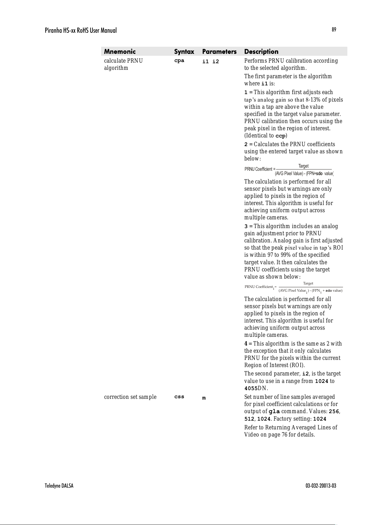
Piranha HS-xx RoHS User Manual
Teledyne DALSA 03-032-20013-03
89
Mnemonic
Syntax
Parameters
Description
calculate PRNU
algorithm
cpa
i1 i2
Performs PRNU calibration according
to the selected algorithm.
The first parameter is the algorithm
where i1 is:
1 = This algorithm first adjusts each
tap’s analog gain so th at 8-13% of pixels
within a tap are above the value
specified in the target value parameter.
PRNU calibration then occurs using the
peak pixel in the region of interest.
(Identical to ccp)
2 = Calculates the PRNU coefficients
using the entered target value as show n
below:
PRNU Coefficient =
Target
(AVG Pixel Value) - (FPN+ value)sdo
The calculation is performed for all
sensor pixels but warnings are only
applied to pixels in the region of
interest. This algorithm is useful for
achieving uniform output across
multiple cameras.
3 = This algorithm includes an analog
gain adjustment prior to PRNU
calibration. Analog gain is first adjusted
so that the peak pixel valu e in tap ’s ROI
is within 97 to 99% of the specified
target value. It then calculates the
PRNU coefficients using the target
value as shown below:
PRNU Coefficient =
Target
(AVG Pixel Value ) - (FPN + value)sdo
i
i
i
The calculation is performed for all
sensor pixels but warnings are only
applied to pixels in the region of
interest. This algorithm is useful for
achieving uniform output across
multiple cameras.
4 = This algorithm is the same as 2 with
the exception that it only calculates
PRNU for the pixels within the current
Region of Interest (ROI).
The second parameter, i2, is the target
value to use in a range from 1024 to
4055DN.
correction set sample
css
m
Set number of line samples averaged
for pixel coefficient calculations or for
output of gla command. Values: 256,
512, 1024. Factory setting: 1024
Refer to Returning Averaged Lines of
Video on page 76 for details.
All manuals and user guides at all-guides.com

Piranha HS-xx RoHS User Manual
03-032-20013-03 Teledyne DALSA
90
Mnemonic
Syntax
Parameters
Description
display pixel coeffs
dpc
x1 x2
Displays the pixel coefficients in the
ord er FPN , PRNU, FPN, PRN U, …
x1 = Pixel start number
x 2= Pixel end number
in a range from 1 to sensor pixel
count.
Refer to Setting a range of Pixel PRNU
Coefficients for details.
end of line sequence
els
i
Sets the end-of-line sequence:
0: Off
1: On
Refer to Refer to 4.5.3 End-of-line
Sequence for details.
enable pixel coefficients
epc
i i
Sets whether pixel coefficients are
enabled or disabled.
The first parameter sets the FPN
coefficients where i is:
0 = FPN coefficients disabled
1 = FPN coefficients enabled
The second parameter sets the PRNU
coefficients where i is:
0 = PRNU coefficients disabled
1 = PRNU coefficients enabled
Refer to section Enabling and Disabling
Pixel Coefficients on page 67 for details.
get camera model
gcm
Reads the camera model number.
get camera parameters
gcp
Reads all of the camera parameters.
get camera serial
gcs
Read the camera serial number.
get camera version
gcv
Displays the firmware version and
FPGA version.
get values
get
s
Retrieves camera values.
get fpn coeff
gfc
x
Read the FPN coefficient
x = pixel number to read in a range
from 1 – sensor pixel count.
Refer to Returning FPN Coefficients on
page 62 for details.
get help
gh
Returns the help screen.
get line
gl
x1 x2
Gets a line of raw video (no digital
processing or test pattern) displaying
one pixel value after another and the
minimum, maximum, and mean value
of the sampled line.
x1 = Pixel start number
x2 = Pixel end number
in a range from 1 to sensor pixel
count.
Refer to Returning a Single Line of
Video on page 75 for details.
All manuals and user guides at all-guides.com
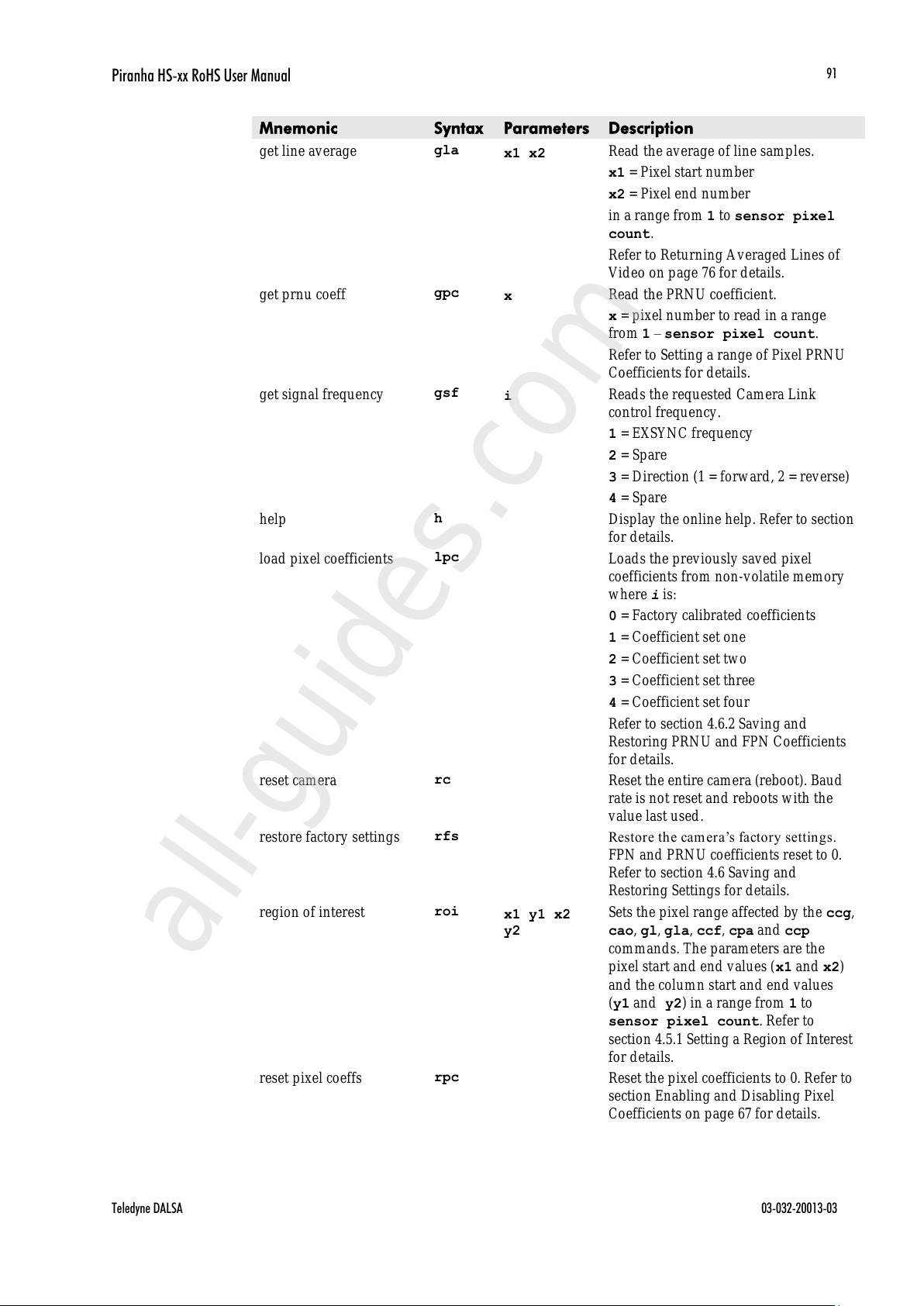
Piranha HS-xx RoHS User Manual
Teledyne DALSA 03-032-20013-03
91
Mnemonic
Syntax
Parameters
Description
get line average
gla
x1 x2
Read the average of line samples.
x1 = Pixel start number
x2 = Pixel end number
in a range from 1 to sensor pixel
count.
Refer to Returning Averaged Lines of
Video on page 76 for details.
get prnu coeff
gpc
x
Read the PRNU coefficient.
x = pixel number to read in a range
from 1 – sensor pixel count.
Refer to Setting a range of Pixel PRNU
Coefficients for details.
get signal frequency
gsf
i
Reads the requested Camera Link
control frequency.
1 = EXSYNC frequency
2 = Spare
3 = Direction (1 = forward, 2 = reverse)
4 = Spare
help
h
Display the online help. Refer to section
for details.
load pixel coefficients
lpc
Loads the previously saved pixel
coefficients from non-volatile memory
where i is:
0 = Factory calibrated coefficients
1 = Coefficient set one
2 = Coefficient set two
3 = Coefficient set three
4 = Coefficient set four
Refer to section 4.6.2 Saving and
Restoring PRNU and FPN Coefficients
for details.
reset camera
rc
Reset the entire camera (reboot). Baud
rate is not reset and reboots with the
value last used.
restore factory settings
rfs
Restor e the cam er a’s factor y settin gs.
FPN and PRNU coefficients reset to 0.
Refer to section 4.6 Saving and
Restoring Settings for details.
region of interest
roi
x1 y1 x2
y2
Sets the pixel range affected by the ccg,
cao, gl, gla, ccf, cpa and ccp
commands. The parameters are the
pixel start and end values (x1 and x2)
and the column start and end values
(y1 and y2) in a range from 1 to
sensor pixel count. Refer to
section 4.5.1 Setting a Region of Interest
for details.
reset pixel coeffs
rpc
Reset the pixel coefficients to 0. Refer to
section Enabling and Disabling Pixel
Coefficients on page 67 for details.
All manuals and user guides at all-guides.com
all-guides.com

Piranha HS-xx RoHS User Manual
03-032-20013-03 Teledyne DALSA
92
Mnemonic
Syntax
Parameters
Description
restore user settings
rus
Restore the camera's last saved user
settings and FPN and PRNU
coefficients. Refer to section 4.6 Saving
and Restoring Settings for details.
set analog gain
sag
t f
Sets the analog gain in dB.
t = Tap value. 0 for all taps or 1-
number of CCD taps for individual
tap selection.
f= gain value specified from –10 to
+10
Refer to Analog Signal Processing:
Setting Analog Gain and Offset on page
54 for details.
set analog offset
sao
t i
Sets the analog offset.
t = 0 for all taps or 1 to number of
CCD taps for individual tap selection.
i= Offset value in a range from 0 to
255 (12-bit LSB). Offset increases w ith
higher values.
Refer to Analog Signal Processing:
Setting Analog Gain and Offset for
details.
set binning horizontal
sbh
m
Sets the horizontal binning value.
Available values are 1, 2, 4, or 8.
Refer to section 4.3.4 Increasing
Sensitivity with Binning on page 38 for
details.
set baud rate
sbr
i
Set the speed of camera serial
communication port. Baud rates: 9600,
19200, 57600, and 115200. Default:
9600. Refer to section Setting Baud Rate
on page 30 for details.
set binning vertical
sbv
m
Sets the vertical binning value.
Available values (not including the HS-
82 model) are 1 to 8.
Available values for the HS-82 model
are 1 to 4.
Refer to section 4.3.4 Increasing
Sensitivity with Binning on page 38 for
details.
set ccd direction
scd
i
Sets the CCD shift direction where:
0 = Forward TDI shift direction.
1 = Reverse TDI shift direction.
2 = Externally controlled direction
control via Camera Link control CC3.
Available only in TDI Mode
All manuals and user guides at all-guides.com

Piranha HS-xx RoHS User Manual
Teledyne DALSA 03-032-20013-03
93
Mnemonic
Syntax
Parameters
Description
set digital offset
sdo
t i
Subtracts the input value from the
video signal prior to FPN correction.
t = Tap value. 0 for all taps or 1-
number of CCD taps for individual
tap selection.
i = Offset in a range from 0 to 511DN.
Refer to
Setting Digital Offset on page62 for
details.
set exposure mode
sem
m
Set the exposure mode:
3 = External SYNC, maximum
exposure time
7 = Internal programmable SYNC,
maximum exposure time. Factory
setting.
set fpn coeff
sfc
x i
Set the FPN coefficient.
x =pixel number within the range 1 to
sensor pixel count.
i= FPN value within the range 0 to
2048 (12-bit LSB).
Refer to Performing FPN Correctionon
page 62 for details.
set fpn range
sfr
x1 x2 i
Set a range of pixel FPN coefficients
x1=first pixel number of the range.
x2=last pixel number of the range
i=coefficient value in a range from 0 to
2048.
Refer to Setting a Range of FPN
Coefficients on page 62 for details.
set low er threshold
slt
i
The pixels below the lower threshold
are checked for and reported in the
end-of-line sequence in a range from 0-
4095. Refer to section 4.5.3 End-of-line
Sequence for details.
set mirror mode
smm
i
Set the cam er a’s m ir ror mod e:
0: Pixels readout left to right (1 to 4096
or 8192)
1: Pixels readout right to left (8092 or
4096 to 1)
Refer to 4.4.4 Setting the Pixel Readout
Direction for details.
All manuals and user guides at all-guides.com
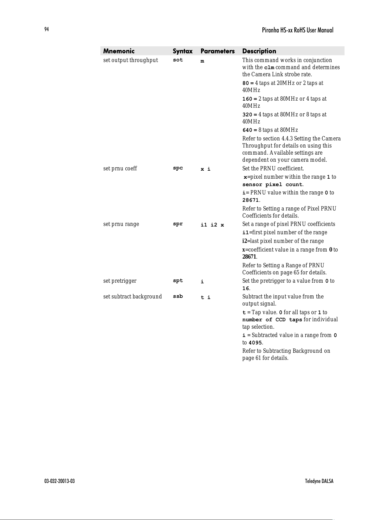
Piranha HS-xx RoHS User Manual
03-032-20013-03 Teledyne DALSA
94
Mnemonic
Syntax
Parameters
Description
set output throughput
sot
m
This command works in conjunction
with the clm command and determines
the Camera Link strobe rate.
80 = 4 taps at 20MHz or 2 taps at
40MHz
160 = 2 taps at 80MHz or 4 taps at
40MHz
320 = 4 taps at 80MHz or 8 taps at
40MHz
640 = 8 taps at 80MHz
Refer to section 4.4.3 Setting the Camera
Throughput for details on using this
command. Available settings are
dependent on your camera model.
set prnu coeff
spc
x i
Set the PRNU coefficient.
x=pixel number within the range 1 to
sensor pixel count.
i= PRNU value within the range 0 to
28671.
Refer to Setting a range of Pixel PRNU
Coefficients for details.
set prnu range
spr
i1 i2 x
Set a range of pixel PRNU coefficients
i1=first pixel number of the range
i2=last pixel number of the range
x=coefficient value in a range from 0 to
28671.
Refer to Setting a Range of PRNU
Coefficients on page 65 for details.
set pretrigger
spt
i
Set the pretrigger to a value from 0 to
16.
set subtract background
ssb
t i
Subtract the input value from the
output signal.
t = Tap value. 0 for all taps or 1 to
number of CCD taps for individual
tap selection.
i = Subtracted value in a range from 0
to 4095.
Refer to Subtracting Background on
page 61 for details.
All manuals and user guides at all-guides.com

Piranha HS-xx RoHS User Manual
Teledyne DALSA 03-032-20013-03
95
Mnemonic
Syntax
Parameters
Description
set sync frequency
ssf
i
Set the frame rate to a value from:
TDI
HS-40-4k40: 3499.87-36563.1
HS-80-8k40: 3499.56-34305.3
HS-80-8k80: 3499.87-68610.6
HS-82-4k80: 3499.87-111111
Area
HS-40-4k40: 1-3783.58
HS-80-8k40: 1-3084.52
HS-80-8k80: 1-6169.03
HS-82-4k80: 1-9017.13
Value round ed up/ down as required.
Refer to
Setting Frame Rate on page 42 for
details.
set system gain
ssg
t i
Set the digital gain.
t = tap selection, either 1 to number
of CCD taps, or 0 for all taps
i = Digital gain in a range from 0 to
65535. The digital video values are
multiplied by this number. Refer to
Setting Digital Gain on page 61 for
details.
stage select
stg
i
Sets the number of TDI stages.
Allowable values (not including the HS-
82 model) are:
16,32, 48, 64,80,96 (default)
Allowable HS-82 values are:
8,16,24,32, 40,48 (default)
Refer to 4.2 Selecting the Number of
CCD Integration Stages for details.
set upper threshold
sut
i
The pixels equal to or greater than the
upper threshold are checked for and
reported in the end-of-line sequence in
a range from 0-4095. Refer to 4.5.3
End-of-line Sequence for details.
set video mode
svm
i
Switch between normal video mode
and test patterns:
0: Normal video mode
1: Test pattern
2: Test pattern
3: Test pattern
Refer to section 4.7.1 Generating a Test
Pattern for details.
set TDI mode
tdi
i
Set the cam er a’s operating m od e.
0: Area Mode
1: TDI Mode
Refer to section 4.5.1 for details.
All manuals and user guides at all-guides.com

Piranha HS-xx RoHS User Manual
03-032-20013-03 Teledyne DALSA
96
Mnemonic
Syntax
Parameters
Description
update gain reference
ugr
Changes 0dB gain to equal the current
analog gain value set with the sag
command.
Refer to section Analog Signal
Processing: Setting Analog Gain and
Offset for details.
verify temperature
vt
Check the internal temperature of the
camera
verify voltage
vv
Ch eck th e camera’s in put voltages and
return OK or fail
write FPN coefficients
wfc
i
Write all current FPN coefficients to
EEROM where i is:
1 = FPN coefficient set one
2 = FPN coefficient set two
3 = FPN coefficient set one
4 = FPN coefficient set two
Refer to section 4.6.2 Saving and
Restoring PRNU and FPN Coefficients
for details.
write PRNU coeffs
wpc
i
Write all current PRNU coefficients to
EEROM where i is:
1 = PRNU coefficient set one
2 = PRNU coefficient set two
3 = PRNU coefficient set one
4 = PRNU coefficient set two
Refer to section 4.6.2 Saving and
Restoring PRNU and FPN Coefficients
for details.
write user settings
wus
Write all of the user settings to EEROM.
Refer to section 4.6.1 Saving and
Restoring Factory and User Settings for
details.
All manuals and user guides at all-guides.com
all-guides.com

Piranha HS-xx RoHS User Manual
Teledyne DALSA 03-032-20013-03
97
Appendix B
Camera Link™ Reference,
Timing, and Configuration Table
Camera Link is a communication interface for vision applications. It provides a
connectivity standard between cameras and frame grabbers. A standard cable connection
will red u ce man u factu rers’ support time an d greatly r ed u ce th e level of com plexity an d
time needed for customers to successfully integrate high speed cameras with frame
grabbers. This is particularly relevant as signal and data transmissions increase both in
complexity and throughput. A standard cable/ connector assembly will also enable
customers to take advantage of volume pricing, thus reducing costs.
The camera link standard is intended to be extremely flexible in order to meet the needs
of different camera and frame grabber manufacturers.
The Teledyne DALSA Camera Link Implementation Road Map (available from the
Knowledege Center on Teledyne DALSA website) details how Teledyne DALSA
standardizes its use of the Camera Link interface.
LVDS Technical Description
Low Voltage Differential Signaling (LVDS) is a high speed, low power, general purpose
interface standard. The standard, known as ANSI/ TIA/ EIA-644, was approved in March
1996. LVDS uses differential signaling, with a nominal signal swing of 350mV differential.
The low signal swing decreases rise and fall times to achieve a theoretical maximum
transmission rate of 1.923 Gbps into a loss-less medium. The low signal swing also means
that the standard is not dependent on a particular supply voltage. LVDS uses current -
mode drivers, which limit power consumption. The differential signals are immune to ±1
V common volt noise.
Camera Signal Requirements
This section provides definitions for the signals used in the Camera Link interface. The
standard Camera Link cable provides camera control signals, serial communication, and
video data.
Video Data
The Channel Link technology is integral to the transmission of video data. Image data and
image enable signals are transmitted on the Channel Link bus. Four enable signals are
defined as:
• FVAL—Frame Valid (FVAL) is defined HIGH for valid lines.
• LVAL—Line Valid (LVAL) is defined HIGH for valid pixels.
All manuals and user guides at all-guides.com
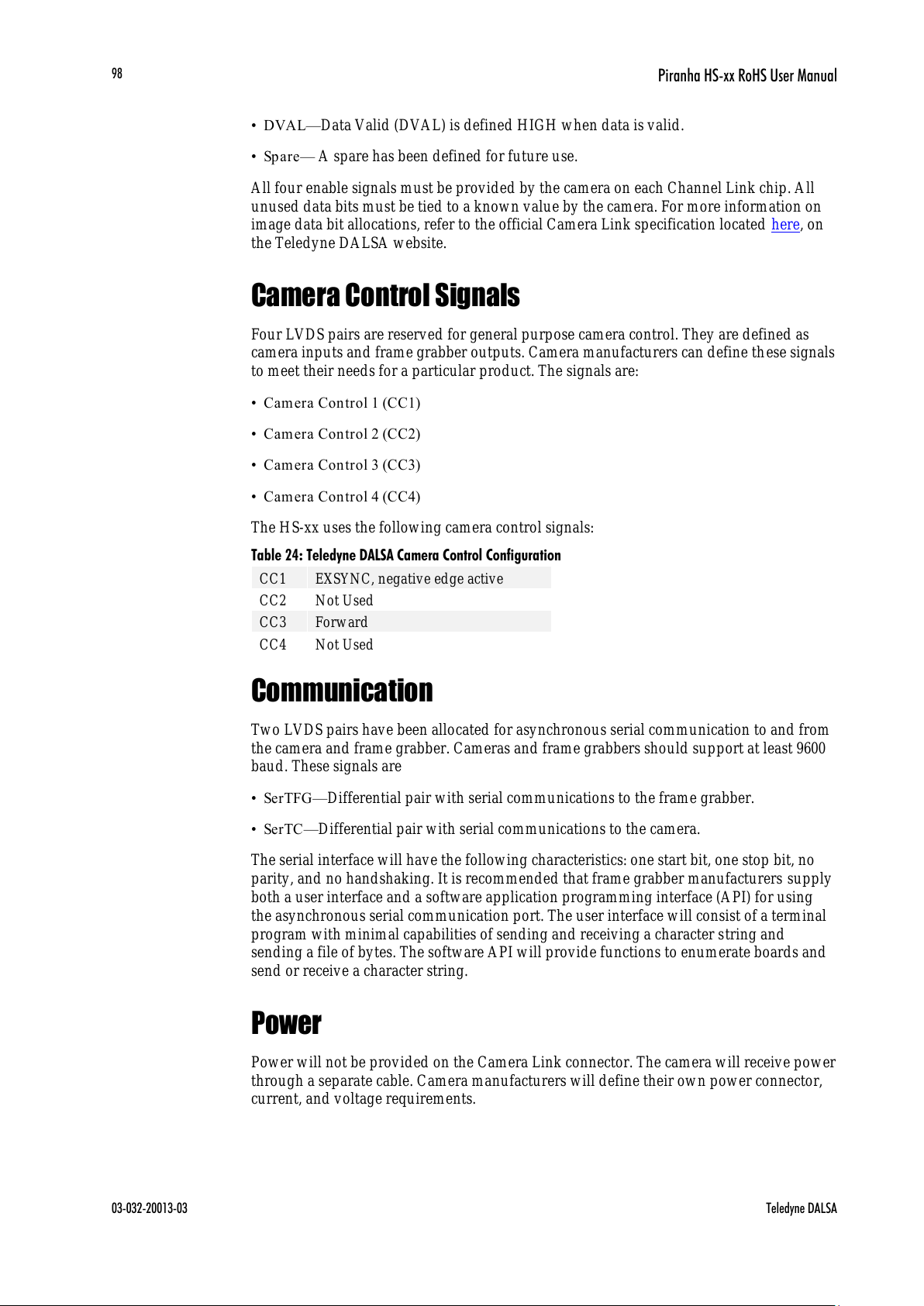
Piranha HS-xx RoHS User Manual
03-032-20013-03 Teledyne DALSA
98
• DVAL—Data Valid (DVAL) is defined HIGH when data is valid.
• Spa re— A spare has been defined for future use.
All four enable signals must be provided by the camera on each Channel Link chip. All
unused data bits must be tied to a known value by the camera. For more information on
image data bit allocations, refer to the official Camera Link specification located here, on
the Teledyne DALSA website.
Camera Control Signals
Four LVDS pairs are reserved for general purpose camera control. They are defined as
camera inputs and frame grabber outputs. Camera manufacturers can define these signals
to meet their needs for a particular product. The signals are:
• Camera Contr ol 1 (CC1)
• Camera Contr ol 2 (CC2)
• Camera Contr ol 3 (CC3)
• Camera Contr ol 4 (CC4)
The HS-xx uses the following camera control signals:
Table 24: Teledyne DALSA Camera Control Configuration
CC1
EXSYNC, negative edge active
CC2
Not Used
CC3
Forward
CC4
Not Used
Communication
Two LVDS pairs have been allocated for asynchronous serial communication to and from
the camera and frame grabber. Cameras and frame grabbers should support at least 9600
baud. These signals are
• SerTFG—Differential pair with serial communications to the frame grabber.
• SerTC—Differential pair with serial communications to the camera.
The serial interface will have the following characteristics: one start bit, one stop bit, no
parity, and no handshaking. It is recommended that frame grabber manufacturers supply
both a user interface and a software application programming interface (API) for using
the asynchronous serial communication port. The user interface will consist of a terminal
program with minimal capabilities of sending and receiving a character string and
sending a file of bytes. The software API will provide functions to enumerate boards and
send or receive a character string.
Power
Power will not be provided on the Camera Link connector. The camera will receive power
through a separate cable. Camera manufacturers will define their own power connector,
current, and voltage requirements.
All manuals and user guides at all-guides.com

Piranha HS-xx RoHS User Manual
Teledyne DALSA 03-032-20013-03
99
Camera Link Bit Definitions
BASE
Configuration
T0
T1 (Note: Entries imply double
frequency pixel rate data
transmission)
Mode
Port A
Bits 0 thru
7
Port B
Bits 0 thru 7
Port C
Bits 0 thru
7
Port A
Bits 0 thru
7
Port B
Bits 0 thru
7
Port C
Bits 0
thru 7
Mode 2
2 Tap 8 bit
Tap 1
LSB..Bit 7
Tap 2
LSB..Bit7
xxxxxxx
N/ A
N/ A
N/ A
Mode 3
2 Tap n bit Where
n=10,12
Tap 1 LSB..
Bit 7
Tap 1 Bits
8,9,10,11,
Tap 2 Bits
8,9,10,11
Tap 2 LSB..Bit
7
N/ A
N/ A
N/ A
Medium
Configuration
T0
Mode
Port A
Bits 0 thru
7
Port B
Bits 0 thru 7
Port C
Bits 0 thru
7
Port D
Bits 0 thru
7
Port E
Bits 0
thru 7
Port F
Bits 0
thru 7
Mode 15
4 Tap 8 bit
Tap 1
LSB..Bit 7
Tap 2 LSB..Bit
7
Tap 3 LSB..Bit
7
Tap 4
LSB...Bit 7
xxxxxxxx
Xxxxxxxx
Mode 16
4 Tap 10/ 12 bit
Tap 1
LSB.. Bit 7
Tap 1 Bits
8,9,10,11,
Tap 2 Bits
8,9,10,11
Tap 2 LSB..Bit
7
Tap 4
LSB…Bit 7
Tap 3
LSB…Bit
7
Tap 3
Bit
8,9,10,11
Tap 4 Bit
8,9,10,11
Full
Configuration
T0
Mode
Port A
LSB…
Bit 7
Port B
LSB…Bi
t 8
Port C
LSB…
Bit 8
Port D
LSB…
Bit 8
Port E
LSB…
Bit 8
Port F
LSB…
Bit 8
Port G
LSB…
Bit 8
Port H
LSB…
Bit 8
Mode 21
8 Tap 8 bit
Tap 1
LSB…
Bit 7
Tap 2
LSB…Bit
7
Tap 3
LSB…
Bit 7
Tap 4
LSB…
Bit 7
Tap 5
LSB…
Bit 7
Tap 6
LSB…
Bit 7
Tap 7
LSB…
Bit 7
Tap 8
LSB…
Bit 7
Camera Link Configuration Tables
The following table provides tap reconstruction information. Teledyne DALSA is working
with the machine vision industry to use this table as the basis for auto configuration. Visit
the Knowledge Center Web site and view the Teledyne DALSA Camera Link
Implementation Road Map document, 03-32-00450, for further details.
All manuals and user guides at all-guides.com
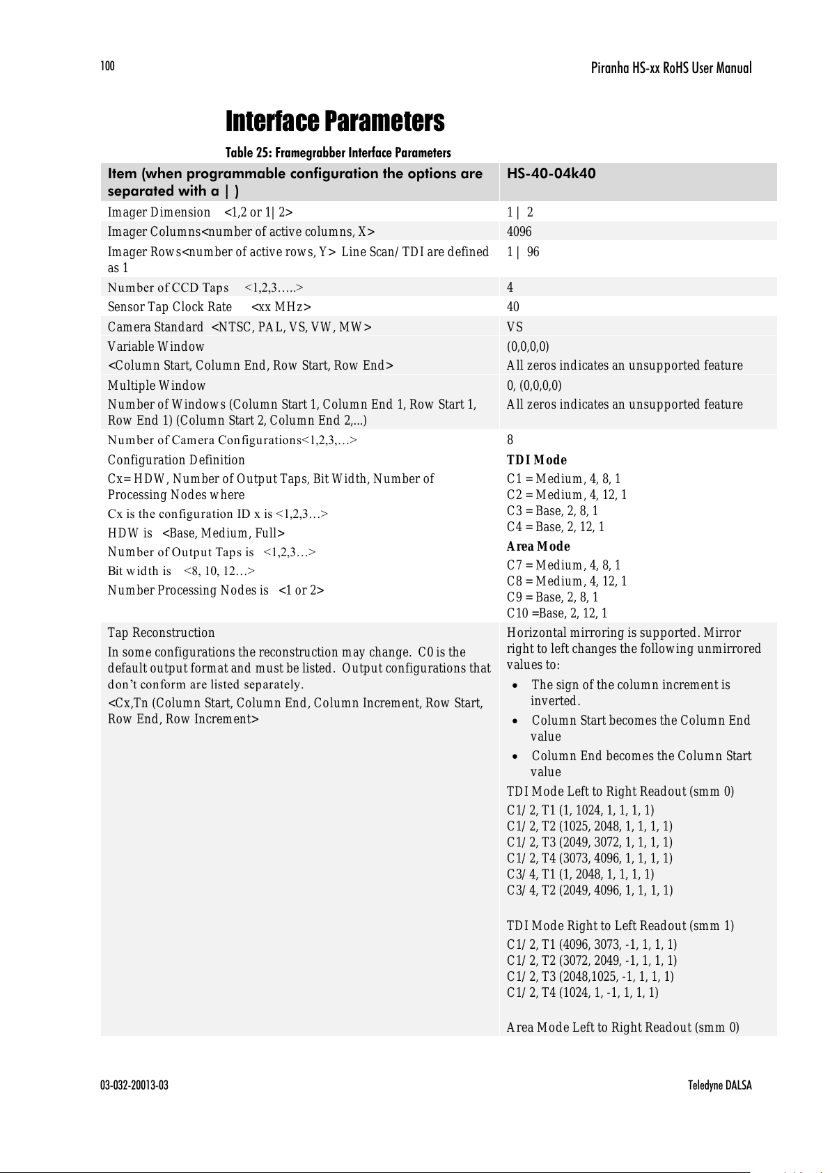
Piranha HS-xx RoHS User Manual
03-032-20013-03 Teledyne DALSA
100
Interface Parameters
Table 25: Framegrabber Interface Parameters
Item (when programmable configuration the options are
separated with a | )
HS-40-04k40
Imager Dimension <1,2 or 1| 2>
1 | 2
Imager Columns<number of active columns, X>
4096
Imager Rows<number of active rows, Y> Line Scan/ TDI are defined
as 1
1 | 96
Number of CCD Tap s <1,2,3…..>
4
Sensor Tap Clock Rate <xx MHz>
40
Camera Standard <NTSC, PAL, VS, VW, MW>
VS
Variable Window
<Column Start, Column End, Row Start, Row End>
(0,0,0,0)
All zeros indicates an unsupported feature
Multiple Window
Number of Windows (Column Start 1, Column End 1, Row Start 1,
Row End 1) (Column Start 2, Column End 2,...)
0, (0,0,0,0)
All zeros indicates an unsupported feature
Number of Cam era Con fig ura tions<1,2,3,…>
8
Configuration Definition
Cx= HDW, Number of Output Taps, Bit Width, Number of
Processing Nodes where
Cx is th e configu ration ID x is <1,2,3…>
HDW is <Base, Medium, Full>
Number of Ou tp u t Tap s is <1,2,3…>
Bit w id th is <8, 10, 12…>
Number Processing Nodes is <1 or 2>
TDI Mode
C1 = Medium, 4, 8, 1
C2 = Medium, 4, 12, 1
C3 = Base, 2, 8, 1
C4 = Base, 2, 12, 1
Area Mode
C7 = Medium, 4, 8, 1
C8 = Medium, 4, 12, 1
C9 = Base, 2, 8, 1
C10 =Base, 2, 12, 1
Tap Reconstruction
In some configurations the reconstruction may change. C0 is the
default output format and must be listed. Output configurations that
don ’t con form are listed separately.
<Cx,Tn (Column Start, Column End, Column Increment, Row Start,
Row End, Row Increment>
Horizontal mirroring is supported. Mirror
right to left changes the following unmirrored
values to:
The sign of the column increment is
inverted.
Column Start becomes the Column End
value
Column End becomes the Column Start
value
TDI Mode Left to Right Readout (smm 0)
C1/ 2, T1 (1, 1024, 1, 1, 1, 1)
C1/ 2, T2 (1025, 2048, 1, 1, 1, 1)
C1/ 2, T3 (2049, 3072, 1, 1, 1, 1)
C1/ 2, T4 (3073, 4096, 1, 1, 1, 1)
C3/ 4, T1 (1, 2048, 1, 1, 1, 1)
C3/ 4, T2 (2049, 4096, 1, 1, 1, 1)
TDI Mode Right to Left Readout (smm 1)
C1/ 2, T1 (4096, 3073, -1, 1, 1, 1)
C1/ 2, T2 (3072, 2049, -1, 1, 1, 1)
C1/ 2, T3 (2048,1025, -1, 1, 1, 1)
C1/ 2, T4 (1024, 1, -1, 1, 1, 1)
Area Mode Left to Right Readout (smm 0)
All manuals and user guides at all-guides.com
 Loading...