

Dalsa FA-80-12M1H-XX-R, FA-81-12M1H-XX-R, FA-80-8M100-XX-R, FA-81-8M100-XX-R, FA-80-4M180-XX-R User Manual
...
Falcon2
Camera User’s Manual
4M, 8M and 12M Area Imaging
P/N: 03-032-20107-04
www.teledynedalsa.com

Notice
© 2017 Teledyne DALSA
All information provided in this manual is believed to be accurate and reliable. No
responsibility is assumed by Teledyne DALSA for its use. Teledyne DALSA reserves the right
to make changes to this information without notice. Reproduction of this manual in whole or
in part, by any means, is prohibited without prior permission having been obtained from
Teledyne DALSA.
Microsoft and Windows are registered trademarks of Microsoft Corporation in the United
States and other countries. Windows, Windows 7, Windows 8 are trademarks of Microsoft
Corporation.
All other trademarks or intellectual property mentioned herein belong to their respective
owners.
Document Date: August 25, 2017
Document Number: 03-032-20107-04
Contact Teledyne DALSA
Teledyne DALSA is headquartered in Waterloo, Ontario, Canada. We have sales offices in
the USA, Europe and Asia, plus a worldwide network of representatives and agents to serve
you efficiently. Contact information for sales and support inquiries, plus links to maps and
directions to our offices, can be found here:
Sales Offices: http://www.teledynedalsa.com/corp/contact/offices/
Technical Support: http://www.teledynedalsa.com/imaging/support/
About Teledyne DALSA
Teledyne DALSA is an international high performance semiconductor and electronics
company that designs, develops, manufactures, and markets digital imaging products and
solutions, in addition to providing wafer foundry services.
Teledyne DALSA Digital Imaging offers the widest range of machine vision components in
the world. From industry-leading image sensors through powerful and sophisticated
cameras, frame grabbers, vision processors and software to easy-to-use vision appliances
and custom vision modules.
2 • The Falcon2 Cameras

Contents
Camera User’s Manual ___________________________________________________________________________________ 1
System Precautions ............................................................................................................................. 6
Precautions .......................................................................................................................... 6
Electrostatic Discharge and the CMOS Sensor ................................................................... 6
The Falcon2 Cameras ____________________________________________________________________________________ 7
Description ........................................................................................................................................... 7
Key Features ....................................................................................................................... 7
Programmability ................................................................................................................... 7
Applications ......................................................................................................................... 7
Part Numbers and Software Requirements ......................................................................................... 8
Camera Performance Specifications ................................................................................................... 9
Certifications ........................................................................................................................................ 10
Shock and Vibration ............................................................................................................................ 10
Supported Industry Standards ............................................................................................................. 11
GenICam ............................................................................................................................. 11
Responsivity & Quantum Efficiency ..................................................................................................... 12
Sensor Cosmetic Specifications .......................................................................................................... 15
Sensor Block Diagram and Pixel Readout .......................................................................................... 16
Mechanicals ......................................................................................................................................... 17
Software and Hardware Setup ______________________________________________________________________________ 18
Minimum Recommended System Requirements ................................................................ 18
Setup Steps: Overview ........................................................................................................................ 18
1. Install and Configure Frame Grabber and Software (including GUI) ............................... 18
2. Connect Camera Link Cables and Power ........................................................................ 18
3. Establish communicating with the camera ....................................................................... 18
4. Check camera LED, settings and test pattern ................................................................. 18
5. Operate the Camera ........................................................................................................ 18
Step 1. Install and configure the frame grabber and Software ............................................................ 19
Install Frame Grabber .......................................................................................................... 19
Install Sapera LT and CamExpert ........................................................................................ 19
Step 2. Connect Power, Data, and Trigger Cables ............................................................................. 19
Power Connector ................................................................................................................. 20
Camera Link Data Connector .............................................................................................. 21
Output Signals, Camera Link Clocking Signals ................................................................... 21
Input Signals, Camera Link .................................................................................................. 21
Frame Start Trigger (EXSYNC) ........................................................................................... 21
LEDs .................................................................................................................................... 21
Step 3. Establish Communication with the Camera ............................................................................ 22
Power on the camera ........................................................................................................... 22
Initialize the frame grabber .................................................................................................. 22
Initialize communication with the camera ............................................................................ 22
Check LED Status ............................................................................................................... 22
Software Interface ................................................................................................................ 22
The Falcon2 Cameras • 3

Camera Operation _______________________________________________________________________________________ 24
Camera Information Category ............................................................................................................. 24
Camera Information Feature Descriptions ........................................................................... 24
Factory Settings ................................................................................................................... 27
Saving and Restoring Camera Settings ............................................................................... 28
Acquisition and Transfer Control Category .......................................................................................... 29
Sensor Control Category ..................................................................................................................... 31
Sensor Control Feature Descriptions ................................................................................... 31
Gain and Black Level Control Details .................................................................................. 37
Set Aspect Ratio .................................................................................................................. 38
Pixel Digitization Bit Depth ................................................................................................... 38
Exposure Controls ............................................................................................................... 38
Exposure Time ..................................................................................................................... 40
Internal Frame Rate ............................................................................................................. 41
I ∕ O Control Category .......................................................................................................................... 42
Event Control Feature Descriptions ..................................................................................... 43
Trigger Modes ...................................................................................................................... 50
I/O Block Diagram ................................................................................................................ 50
CameraLink Control Lines ................................................................................................... 51
Opto-coupled Inputs ............................................................................................................ 51
Opto-Coupled Outputs ......................................................................................................... 52
Advanced Processing Control Category .............................................................................................. 52
Advanced Processing Control Feature Descriptions ........................................................... 54
Flat Field Correction and Defective Pixel Detection Overview ............................................ 66
How to do an FFC Setup in the Camera .............................................................................. 68
How to do a FFC Setup via Sapera CamExpert .................................................................. 70
Defective Pixel Detection and Replacement ........................................................................ 75
Image Format Controls Category ........................................................................................................ 77
Test Patterns ....................................................................................................................... 81
Multiple AOI Mode ............................................................................................................... 84
Camera Link Transport Layer Category .............................................................................................. 85
Camera Link Transport Layer Feature Description .............................................................. 86
Serial Port Control Category ................................................................................................................ 89
Feature Description ............................................................................................................. 89
Automatic Serial Speed Detection ....................................................................................... 90
File Access Control Category .............................................................................................................. 90
File Access via the CamExpert Tool .................................................................................... 94
Appendix A: Camera Link _________________________________________________________________________________ 95
Appendix B: Camera, Frame Grabber Communication ___________________________________________________________ 100
Appendix C: Cleaning the Sensor Window ____________________________________________________________________ 102
4 • The Falcon2 Cameras
Output Signals, Camera Link Clocking Signals ................................................................... 95
Camera Link cable quality and length .................................................................................. 95
Data Connector: Camera Link ............................................................................................. 95
Full Configuration ................................................................................................................. 97
Extended Configurations ..................................................................................................... 98
Setting Up Communication between the Camera and the Frame Grabber ......................... 100

Appendix D: Internal Flat Field Calibration Algorithms ___________________________________________________________ 103
Offset (FPN) Calibration ...................................................................................................................... 103
Pixel Replacement Calibration ............................................................................................................ 103
Gain (PRNU) Calibration ..................................................................................................................... 103
Appendix E: Three Letter Commands ________________________________________________________________________ 105
Putting Camera in TLC Mode .............................................................................................................. 105
Setting the Sapera’s COM Port Mapping ............................................................................................ 106
Getting Started .................................................................................................................................... 106
The Help Command (h or ?) ................................................................................................ 106
Getting Parameters (gcp or get) .......................................................................................... 107
Commands .......................................................................................................................................... 107
EMC Declaration of Conformity _____________________________________________________________________________ 122
Revision History _________________________________________________________________________________________ 123
Index _________________________________________________________________________________________________ 124
The Falcon2 Cameras • 5

System Precautions
Precautions
Read these precautions and this manual carefully before using the camera.
Confirm that the camera’s packaging is undamaged before opening it. If the packaging is
damaged please contact the related logistics personnel.
Do not open the housing of the camera. The warranty is voided if the housing is opened.
Keep the camera housing temperature in a range of 0 °C to +65 °C during operation.
Do not operate the camera in the vicinity of strong electromagnetic fields. In addition, avoid
electrostatic charging, violent vibration, and excess moisture.
To clean the device, avoid electrostatic charging by using a dry, clean absorbent cotton
cloth dampened with a small quantity of pure alcohol. Do not use methylated alcohol. To
clean the surface of the camera housing, use a soft, dry cloth. To remove severe stains use
a soft cloth dampened with a small quantity of neutral detergent and then wipe dry. Do not
use volatile solvents such as benzene and thinners, as they can damage the surface finish.
Further cleaning instructions are below.
Though this camera supports hot plugging, it is recommended that you power down and
disconnect power to the camera before you add or replace system components.
Electrostatic Discharge and the CMOS Sensor
Image sensors and the camera bodies housing are susceptible to damage from electrostatic
discharge (ESD). Electrostatic charge introduced to the sensor window surface can induce
charge buildup on the underside of the window that cannot be readily dissipated by the dry
nitrogen gas in the sensor package cavity. The charge normally dissipates within 24 hours
and the sensor returns to normal operation.
Additional information on cleaning the sensor window and protecting it against dust, oil,
blemishes, and scratches can be found in Appendix C: Cleaning the Sensor Window.
6 • The Falcon2 Cameras

The Falcon2 Cameras
Description
The Falcon2 4M, 8M, and 12M are Teledyne DALSA’s new generation of area scan cameras.
The Falcon2 cameras incorporate large resolutions and increased frame rates, enabling high
speed image capture with superb spatial resolution.
Features such as global shutter and improved image quality make the Falcon2 cameras the
camera of choice in applications where throughput, resolution, and dynamic range
matter. In addition, global shuttering removes unwanted smear and time displacement
artefacts related to rolling shutter CMOS devices.
Inside the Falcon2 cameras are our latest 4, 8 and 12 megapixel CMOS sensors which have
reduced dark noise levels and improved dark offset, FPN (fixed pattern noise) and PRNU
(Pixel Response Non-Uniformity) levels. In addition, region of interest features create
opportunities for higher frame rates and new applications.
The cameras are compliant with Camera Link™ specifications, delivering 8 or 10 bits of data
on 8 or 10 taps (frame rates are specified at 8 bits). Further, the M42x1 thread opening
allows the use of your lens of choice.
Key Features
• 12, 8 and 4 mega pixels
• Selectable 4:3 or 1:1 aspect ratios
• Global shutter
• Exposure control
• Faster frame rates through windowing
• Good NIR response
• Built-in FPN and PRNU correction
Programmability
• Adjustable digital gain and offset
• 8 or 10 bit selectable output
• Adjustable integration time and frame rate
• Test patterns and camera diagnostics
Applications
• Automated Optical Inspection (AOI)
• 3D imaging—laser profiling
• Semiconductor wafer inspection
• Solar panel inspection
• Electronics manufacturing
• Surface and bump inspection
• 3D solder paste inspection
• General machine vision
The Falcon2 Cameras • 7

Part Numbers and Software Requirements
Model Number
Description
Software
Product Number / Version Number
The camera is available in the following configurations.
Table 1: Camera Models Overview
FA-80-12M1H-XX-R 12M pixel monochrome Camera Link.
FA-81-12M1H-XX-R 12M pixel color Camera Link.
FA-80-8M100-XX-R 8M pixel monochrome Camera Link.
FA-81-8M100-XX-R 8M pixel color Camera Link.
FA-80-4M180-XX-R 4M pixel monochrome Camera Link.
FA-81-4M180-XX-R 4M pixel color Camera Link.
Table 2: Software
Camera firmware Embedded within camera
GenICam™ support (XML camera description file) Embedded within camera
Recommended: Sapera LT, including CamExpert GUI application and
GenICam for Camera Link imaging driver.
Version 7.20 or later
8 • The Falcon2 Cameras

Camera Performance Specifications
Specifications
Performance
Mechanicals
Compliance
Mono Operating Ranges
Units
Notes
Table 3: Camera Performance Specifications
Resolution 4 : 3 aspect ratio: 12M—4096 (H) x 3072 (V)
8M—3328 (H) x 2502 (V)
4M—2432 (H) x 1728 (V)
1 : 1 aspect ratio: 8M—2816 (H) x 2816 (V)
4M—2048 (H) x 2048 (V)
Pixel Rate 8 x 76 MHz or 10 x 76 MHz
Max. Frame Rate 12M—58 fps / 8M—90 fps / 4M—168 fps, 10 taps*
Pixel Size 6 µm x 6 µm
Exposure Time 20 µs minimum
Bit Depth 8 bits or 10 bits, Camera Link
Dynamic Range Mono** 58 dB, typical
Dynamic Range Color** 55 dB Green
50 dB Blue
51 dB Red
Output Format, Taps 8 or 10 tap interleaved
Operating Temp 0 °C to 50 °C, front plate temperature
Connectors and
Data Interface Full or Extended Camera Link—2 x SDR26
Power Connector Hirose 12-pin circular
Power Supply + 12 V to + 24 V DC
Power Dissipation 9.5 W, typical
Mini-USB connector Future use
Lens Mount M42 x 1 (F mount optional)
Sensor Alignment ± 0.2º in X-Y directions
Size 60 mm (H) x 60 mm (W) x 80.5 mm (D)
Mass < 300 g
Regulatory Compliance CE and RoHS
* Maximum frame rates are dependent on the aspect ratio used.
**Typical, 12M, 10 Bits per pixel (bpp), sensor bit depth
Random Noise DN rms 1.3* Typical, FFC enabled
Responsivity DN/(nJ/cm2) See graph Figure 1.
DC Offset DN 0 FFC enabled
Antiblooming >1000 x Saturation
FPN DN rms 1.7* Typical, FFC enabled
PRNU DN rms 2.6* Typical, FFC enabled
Integral non-linearity DN < 2 %
*12M, 10 bbp, 8 taps / 10 bits Camera Link
The Falcon2 Cameras • 9

Color Operating Ranges
Units
Notes
Random Dark Noise DN rms Green – 1.74*
Compliance
• Random vibration per MIL-STD-810F at 25 G2/HZ [Power Spectral
Density] or 5 RMS
Blue –3.06*
Red –2.72*
Broadband Responsivity DN/(nJ/cm2) See graph Figure 2.
DC Offset DN 0 FFC enabled
Antiblooming >1000 x Saturation
FPN DN rms Green –1*
Blue –1.8*
Red –1.5*
PRNU DN rms Green –2.2*
Blue –3.1*
Red –2.9*
Integral non-linearity DN < 2 %
*12M, 10bpp, 8taps/10bits Camera Link
Table 4: Frame Rates, Aspect Ratio, and Resolution Comparison
Resolution Aspect Ratio Maximum
Column
12M 4:3 4096 3072 58 58 58
8M 1:1 2816 2816 90 89 66
8M 4:3 3328 2502 86 86 74
4M 1:1 2048 2048 148 122 91
4M 4:3 2432 1728 168 145 108
* Sensor bits per pixel
An online frame rate calculator is available from the Falcon2 product page on the Teledyne
DALSA site, here
.
Maximum
Rows
Frame Rate
8 BPP*
Frame Rate
9 BPP*
Typical, FFC enabled
Typical, FFC enabled
Typical, FFC enabled
Frame Rate
10 BPP*
Certifications
EN 55011, CISPR 11, EN 55022, CISPR 22, FCC Part 15, and ICES-003 Class A Emissions Requirements.
EN 55024, and EN 61326-1 Immunity to Disturbance.
Shock and Vibration
The cameras meet or exceed the following specifications:
• Shock testing 75 G peak acceleration per MIL-STD-810F
10 • The Falcon2 Cameras

Supported Industry Standards
GenICam
The cameras are GenICam™ compliant. The cameras implement a superset of the GenICam
Standard Features Naming Convention specification V1.5. This description takes the form of
an XML device description file complying with the syntax defined by the GenApi module of
the GenICam specification. The camera uses the GenICam Generic Control Protocol (GenCP
V1.0) to communicate over the Camera Link serial port. Additional information on GenICam
can be found here: www.genicam.org
.
The Falcon2 Cameras • 11

Responsivity & Quantum Efficiency
The responsivity graph describes the camera’s response to different wavelengths of light
(excluding lens and light source characteristics).
Figure 1: Falcon2 Monochrome 8M Spectral Responsivity
Note: 8 Taps, 10 bits Camera Link, FFC on, 24 fps (except 400 nm, measured at 10 fps), ND 0.3 filtered light
12 • The Falcon2 Cameras

Figure 2: Falcon2 Color 12M (4096x3072) Spectral Responsivity
30
25
]
2
20
15
10
Red
GreenRed
GreenBlue
Blue
Responsivity [DN/nJ/cm
5
0
400 440 480 520 560 600 640 680 720 760 800 840 880
Wavelength (nm)
Note: 8 taps 10 bits Camera link, 9 Bit sensor digitization, FFC on, color corrected, 4 fps (except for color red, which used
different frame rate at wavelength 560nm and below: 400~480nm was done at 1.8 fps, 500 nm was done at 4 fps and 520~560),
BG 38 filtered light
The Falcon2 Cameras • 13

Figure 3: Quantum Efficiency
[INSERT QE GRAPH HERE]
14 • The Falcon2 Cameras

Sensor Cosmetic Specifications
Specification
The following table lists the current cosmetic specifications for the Teledyne DALSA sensor
used in the Falcon2 series.
Feature /
Unit
MIN TYP
MAX
Notes
Dark Pixel Definition absolute output level
Dark Pixel Count # 50
Light Pixel Definition deviates from frame
average
Average Frame
Output Level
Tolerated Count # 50
Detection Threshold - Groups of
Tolerated Count # 7 Based on estimation algorithm
Detection Threshold Groups of
Tolerated Count # - 0
Glass Spot Defect
Definition
DN > 500 4 frame average
% ± 30 4 frame average image
for scene & dark correction
% SAT 40 50 60 Illuminated with diffused
light source
combined dark and light pixel
dark and light pixels
Combined dark and light pixel
dark and light pixels
defects/kernel 8 / 3x3 8 / 3x3 Illuminated with aperture
defects
defects
(collimated) light source
Detection Threshold % of avage ± 8 4 frame average - any pixel
Tolerated Count # 1 1 spot of 9 pixels allowed. No limit
Column Defect
Definition
Column Defect Count # 0
Row Defect Definition defects/kernel > 8 / 12x1
Row Defect Count # 0
Table 5: Sensor Cosmetic Specifications
Definition of Blemishes
• Dark pixel defect: Pixel whose signal, in dark, exceeds 500 DN.
• Light pixel defect: Pixel whose signal, at nominal light (illumination at 50 % of the
linear range), deviates more than ±30 % from its neighbouring pixels.
The Falcon2 Cameras • 15
defects/kernel > 8 / 1x12
outside ± 8% of average
on spots below 9 pixels

• Cluster defect: A grouping of at most 2 to 5 pixel defects within a sub-area of 3*3
pixels.
• Glass Spot defect: A grouping of 9 pixel defects within a sub-area of 3*3 pixels.
• Column defect: A column that has more than 8 defect pixels in a 1*12 kernel.
• Row defect: A row that has more than 8 defects in a 12*1 kernel.
• Test conditions Temperature: 40 °C.
• Integration Time: 12 ms.
Sensor Block Diagram and Pixel Readout
Figure 4: 8 Tap Camera Link Configuration Sensor Block Diagram. 8M Color Camera at Aspect Ratio 4 : 3.
Notes:
• As viewed looking at the front of the camera without a lens. (The Teledyne DALSA
logo on the side of the case will be right-side up.)
• The monochrome camera uses the same layout, but without the color filters.
• The color camera model has a Bayer filter applied to the CMOS sensor to allow for
color separation. Each individual pixel is covered by either a red, green, or blue filter
as shown in the figure above. The camera outputs raw color data—no color
interpolation is performed. Full RGB images can be obtained by performing color
interpolation on the frame grabber or host PC. For reference the green pixels
horizontally adjacent to the red pixels will be referred to as Green-Red pixels while
Green-Blue will referred to the Green pixels next to the blue pixels.
16 • The Falcon2 Cameras

Mechanicals
Figure 5: Camera Mechanical
[ADD MECHANICAL PDF HERE]
The Falcon2 Cameras • 17

Software and Hardware Setup
Minimum Recommended System Requirements
To achieve best system performance, the following minimum requirements are
recommended:
• High bandwidth frame grabber, e.g. DALSA PX8 Full Camera link frame grabber (Part
# OR-X8CO-XPF00).
• PCI x8 slot.
• Operating system: Windows XP 32-bit.
Setup Steps: Overview
Take the following steps in order to setup and run your camera system. They are described
briefly below and in more detail in the sections that follow.
1. Install and Configure Frame Grabber and Software (including
GUI)
Install a frame grabber that supports the camera’s bandwidth.Follow the manufacturer’s
installation instructions.
A GenICam™ compliant XML device description file is embedded within the Falcon2 firmware
allowing GenCP compliant applications to know the camera’s capabilities immediately after
connection.
Installing SaperaLT gives you access to the CamExpert GUI, a GenCP compliant application.
The SaperaLT software is available from the Falcon2 page of the Teledyne DALSA Web site,
.
here
2. Connect Camera Link Cables and Power
• Connect the Camera Link cables from the camera to the computer.
• Connect a power cable from the camera to a +12 VDC to +24 VDC (±5 %) power
supply.
• Note: once powered down, the camera must remain off for a minimum of 10 seconds
before being turned on again in order to fully reboot.
3. Establish communicating with the camera
Start the software and establish communication with the camera.
4. Check camera LED, settings and test pattern
Ensure the camera is operating properly by checking the LED, the current, active settings,
and by acquiring a test pattern.
5. Operate the Camera
18 • Software and Hardware Setup

At this point you will be ready to start operating the camera in order to acquire images, set
!
camera functions, and save settings.
Step 1. Install and configure the frame grabber
and Software
Install Frame Grabber
Install a compatible Camera link frame grabber according to the manufacturer’s description.
We recommend the X64 Xcelera-CL PX8 frame grabber or equivalent, described in detail on
the teledynedalsa.com site here
Install Sapera LT and CamExpert
Communicate with the camera using a Camera Link-compliant interface. We recommend
you use CamExpert. CamExpert is the camera interfacing tool supported by the Sapera
library and comes bundled with SaperaLT. Using CamExpert is the simplest and quickest
way to send commands to and receive information from the camera.
Camera link Environment
These cameras implement the Camera link specification, which defines the device
capabilities.
The Camera link XML device description file is embedded within the camera firmware
allowing Camera link-compliant applications to recognize the camera’s capabilities
immediately after connection.
.
Step 2. Connect Power, Data, and Trigger Cables
Note: the use of cables types and lengths other than those specified may result in increased
emission or decreased immunity and performance of the camera.
Figure 6: Input and Output, trigger, and Power Connectors
WARNING! Grounding Instructions
Software and Hardware Setup • 19

!
Static electricity can damage electronic components. It’s critical that you discharge any
Pin
Description
Pin
Description
1
3
4 5 6
9
10
11
!
static electrical charge by touching a grounded surface, such as the metal computer chassis,
before performing handling the camera hardware.
Power Connector
WARNING: It is extremely important that you apply the appropriate voltages to
your camera. Incorrect voltages may damage the camera. Input voltage
requirement: +12 VDC to +24 VDC (± 5 %), 2 Amps. Before connecting power to
the camera, test all power supplies.
Figure 7: 12-pin Hirose Circular Male Power Plug—Power Connector
Table 6. Power Plug Pinout
1 GND 7 OUT2+
2 +12 V to +24 V DC 8 OUT2-
3 OUT1- 9 NC
4 OUT1+ 10 NC
5 IN1-/Trigger 11 IN2+/Trigger
6 IN1+/Trigger 12 IN2-/Trigger
2
12
8
7
WARNING: When setting up the camera’s power supplies follow these guidelines:
• Apply the appropriate voltages.
• Protect the camera with a 2 amp slow-blow fuse between the power supply and
the camera.
• Do not use the shield on a multi-conductor cable for ground.
20 • Software and Hardware Setup

• Keep leads as short as possible in order to reduce voltage drop.
Color of Status LED
Meaning
• Use high-quality linear supplies in order to minimize noise.
Note: If your power supply does not meet these requirements, then the camera
performance specifications are not guaranteed.
Camera Link Data Connector
The cameras use two mini-Camera Link SDR-26 cables transmitting the Camera Link Full or
Extended configuration. For a description of the connectors and the Full and Extended
configurations refer here, Data Connector: Camera Link
.
Output Signals, Camera Link Clocking Signals
These signals indicate when data is valid, allowing you to clock the data from the camera to
your acquisition system. These signals are part of the Camera Link configuration and you
should refer to the Camera Link Implementation Road Map, available at our
Center, for the standard location of these signals.
Knowledge
Input Signals, Camera Link
The camera accepts control inputs through the mini-Camera Link SDR-26F connector.
The camera ships (factory setting) in internal sync, and internally triggered integration.
Frame Start Trigger (EXSYNC)
The EXSYNC signal tells the camera when to integrate and readout the image. It can be
either an internally generated signal by the camera, or it can be supplied externally via CC,
GPIO, and software command.
LEDs
The camera is equipped with an LED on the back to display the operational status of the
camera. The table below summarizes the operating states of the camera and the
corresponding LED states. When more than one condition is active, the LED indicates the
condition with the highest priority.
Off No power or hardware malfunction
Red solid Warning (e.g. temperature)
Red solid Fatal error state
Blue solid Upgrading internal firmware
Blue slow blinking Camera waiting for warm up to complete
Blue solid At initial power up and when acquisition is disabled. This happens when changing a
Green solid Free-running acquisition
camera feature that effects the image output (e.g. aoi, bit depth, etc.)
Software and Hardware Setup • 21

Step 3. Establish Communication with the Camera
Power on the camera
Turn on the camera’s power supply. You may have to wait up to 60 seconds for the camera
to warm up and prepare itself for operation. The camera must boot fully before it will be
recognized by the GUI—the LED turns green once the camera is ready.
Initialize the frame grabber
1. Start Sapera CamExpert (or an equivalent GenCP-compliant interface) by double
clicking the desktop icon created during the software installation.
2. CamExpert will search for Sapera devices installed on your system. In the Devices
list area on the left side of the GUI, the connected frame grabber will be shown.
3. Select the frame grabber device by clicking on its name.
Note: The first time you set up the camera you will need to establish a communication link
between the camera and frame grabber. Instructions are available in the appendix, here
Initialize communication with the camera
1. Start a new Sapera CamExpert application (or equivalent Camera Link compliant
interface) by double clicking the desktop icon created during the software
installation.
2. CamExpert will search for Sapera devices installed on your system. In the Devices
list area on the left side of the GUI, the connected Falcon2 camera will be shown.
3. Select the Falcon2 camera device by clicking on the camera’s user-defined name. By
default the camera is identified by its serial number.
.
Check LED Status
At this point, if the camera is operating correctly the diagnostic LED will flash blue for
approximately 10 seconds and then turn solid green.
Software Interface
All the camera features can be controlled through the GUI. For example, under the Sensor
Control menu in the camera window you can control the frame rate and exposure times.
Note: the camera uses two instances of CamExpert. One window controls the camera and
one displays the output received from the frame grabber.
Also Note: If CamExpert is running during a camera reset operation, then you will have to
reload the GUI window used to control the camera once the camera is powered up again. Do
this by either: 1) closing and reopening the CamExpert window, or 2) by going to “Image
Viewer” in the “Device” tab and selecting the camera again.
22 • Software and Hardware Setup

Figure 8: Two CamExpert windows shown: one connected to the frame grabber and one connected to the camera
At this point you are ready to start operating the camera in order to acquire images, set
camera functions, and save settings.
Software and Hardware Setup • 23

Camera Operation
Name
DeviceVendorName
Camera Information Category
The camera information group provides general information about the camera. Parameters
such as camera model and firmware version uniquely identify the connected device. As well,
temperature can be monitored and user sets can be save and loaded to and from the
camera’s non-volatile memory using the features grouped here.
In this category, the number of features shown is identical whether the view is Beginner,
Expert, or Guru. Features listed in the description table but tagged as Invisible are usually
for Teledyne DALSA or third party software usage—and not typically required by end-user
applications.
Figure 9: Camera Information Category in CamExpert
Camera Information Feature Descriptions
The following table describes these parameters along with their view attribute and in which
firmware version the feature was introduced.
Additionally, the Name category indicates which parameter is a member of the DALSA
Features Naming Convention (using the tag DFNC), versus the GenICam Standard Features
Naming Convention (SFNC), and which is a custom camera feature. As Falcon2 capabilities
evolve the firmware release tag will increase; thereby identifying the supported function
package.
Display Name [Device] Vendor Name
24 • Camera Operation

Name Space SFNC
Name
DeviceModelName
Name
DeviceFamilyName
Name
DeviceVersion
Name
DeviceFirmwareVersion
Name
DeviceTemperatureSelector
Firmware Release 00
Visibility Beginner
Access Read-only
Type String
Values Teledyne DALSA
Display Name [Device] Model Name
Name Space Standard
Firmware Release 00
Visibility Beginner
Access Read-only
Type String
Values e.g. ― FA_80_8M100_01
Display Name [Device] Family Name
Name Space Standard
Firmware Release 00
Visibility Beginner
Access Read-only
Type String
Values Falcon2
Display Name Device Version
Name Space Standard
Firmware Release 00
Visibility Beginner
Access Read-only
Type String
Values e.g. ―255.90.259
Notes This is an automatically generated number that specifically identifies the software build.
Display Name Firmware Version
Name Space Standard
Firmware Release 00
Visibility Beginner
Access Read-only
Type String
Values e.g. ― 03-081-20261-05
Notes The release number of the camera's firmware.
Display Name [Device] Temperature Selector
Name Space Standard
Firmware Release 00
Visibility Beginner
Access Read-Write
Camera Operation • 25

Type Enumeration
Name
DeviceTemperature
Name
DeviceUserID
Name
UserSetDefaultSelector
Name
UserSetSelector
Values Sensor - temperature sensor on sensor board
Notes Changing this value will force the camera to read and update the DeviceTemperature
Display Name Temperature ( C )
Name Space Standard
Firmware Release 00
Visibility Expert
Access Read-only
Type Float
Units degrees Celsius
Values 0 - 100 C
Notes Depending on the host application (e.g. GUI). This value is a polled value and may
Display Name Device User ID
Name Space Standard
Firmware Release 00
Visibility Beginner
Access Read-Write
Type String
Values e.g. ― My Camera
Notes This feature is automatically saved to the camera's non volatile memory when it is written.
Mainboard- temperature sensor on main board
Feature.
automatically be updated every second. Otherwise the value will only be updated upon
connection or when the temperature selector is changed.
Display Name [User Set Default Selector] Power-up Configuration
Name Space Standard
Firmware Release 00
Visibility Beginner
Access Read-Write
Type Enumeration
Values None - no default set is loaded. The camera uses model default values and no factory
Notes Selects the camera configuration set to load and make active on camera power-up or
Display Name User Set Selector
Name Space Standard
Firmware Release 00
Visibility Beginner
Access Read-Write
Type Enumeration
Values Factory - factory calibrated defaults
calibrated values
Factory - load factory calibrated defaults
UserSetx― load previously saved user set x (where x is number between 1 and 4)
reset. The camera configuration sets are stored in camera non-volatile memory.
The feature value automatically saved to the camera's non-volatile memory when it is
written.
26 • Camera Operation

UserSetx― previously saved user set x (where x is number between 1 and 4 )
Name
UserSetLoad
Name
UserSetSave
Name
deviceDFNCVersionMajor
Name
deviceDFNCVersionMajor
Notes Selects the camera configuration set to load feature settings from or save current feature
Display Name User Set Load
Name Space Standard
Firmware Release 00
Visibility Beginner
Access Read-Write
Type Command
Notes Loads the camera configuration set specified by the User Set Selector feature, from the
Display Name User Set Save
Name Space Standard
Firmware Release 00
Visibility Beginner
Access Read-Write
Type Command
Notes Saves the camera configuration set specified by the User Set Selector feature, to the
settings to. The Factory set contains default camera feature settings. Disabled when
flatfieldCorrectionMode = Calibration.
camera and makes it active. Disabled when flatfieldCorrectionMode = Calibration.
camera. Disabled when flatfieldCorrectionMode = Calibration or UserSetSelector = Factory.
Invisible Features
Display Name DFNC Major revision
Name Space DFNC
Firmware Release 00
Visibility Invisible
Access Read-only
Type Integer
Values 1
Notes Major revision of Dalsa Feature Naming Convention which was used to create the device’s
Display Name DFNC Major revision
Name Space DFNC
Firmware Release 00
Visibility Invisible
Access Read-only
Type Integer
Values 0
Notes Minor revision of Dalsa Feature Naming Convention which was used to create the device’s
XML.
XML.
Factory Settings
• The camera ships and powers up for the first time with the following factory settings:
Camera Operation • 27
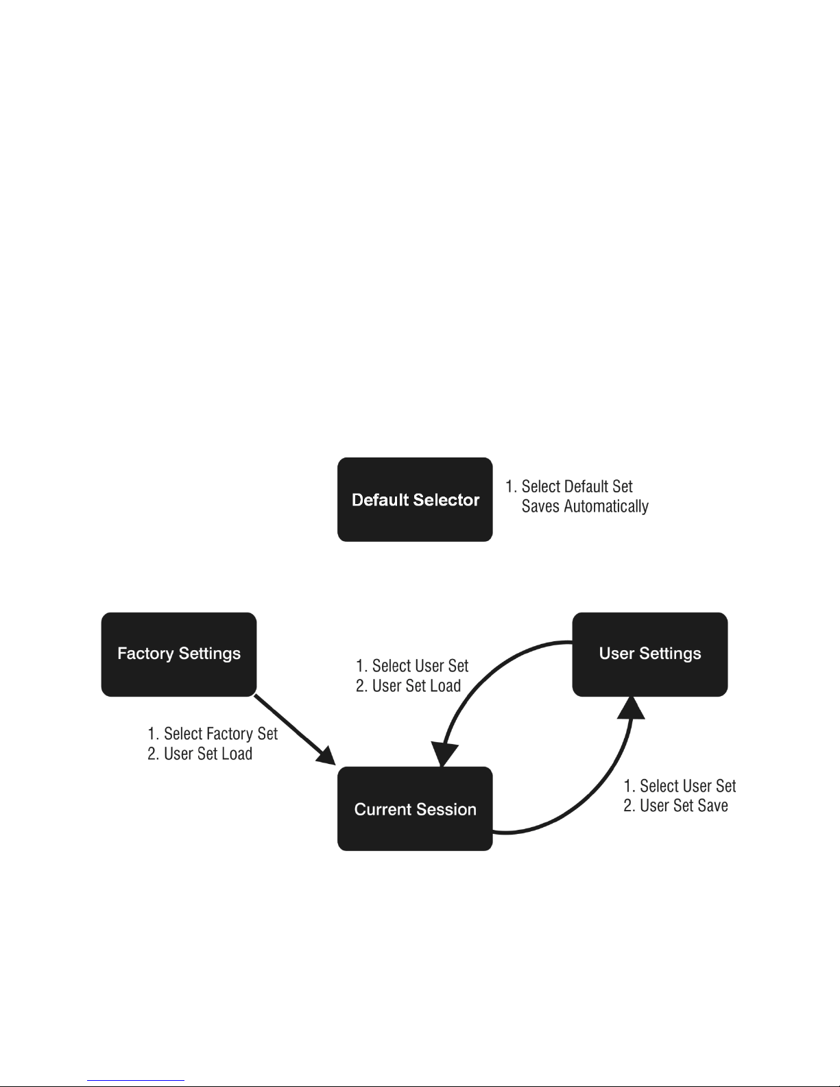
• Flat field coefficients enabled (calibrated in internal exposure mode, non-concurrent
readout and integration).
• Internal exposure mode (internal frame rate and exposure time).
• Maximum frame rate and exposure time.
• Extended Camera Link mode 10 taps, 8 bits, 76 MHz pixel rate.
• 4:3 aspect ratio.
Saving and Restoring Camera Settings
When the user changes a camera parameter, the settings are stored in the camera’s volatile
memory and will be lost if the camera resets or is powered down. To save these settings for
reuse, they must be saved to the camera’s non-volatile memory using the User Set Save
parameter. Previously saved user setting (User Set 1 to 4) or the factory settings can be
restored using the User Set Selector and User Set Load parameters.
Either the Factory or one of the User settings can be specified as the Default Set by
selecting it in the User Set Default Selector. The chosen set is automatically loaded when
the camera is reset or powered up. It should also be noted that the value of Default Selector
will automatically get save in non-volatile memory whenever it is changed
The relationship between these three settings is illustrated in Figure 10.
Note: If a test pattern is active when you save the User set, the camera will turn off all
digital processing upon restart. For example:
1. Set the test image selector to FPN Diagonal Pattern.
2. Do FPN Calibration and save the coefficient set.
3. Change the FFC mode to ActiveAll.
28 • Camera Operation
Figure 10: Relationship between the Camera Settings

4. Set the default selector to UserSet1.
Name
DeviceRegistersStreamingStart
5. Save User Set 1.
6. Power cycle the camera.
7. Reconnect to the camera through CamExpert.
8. The FFC mode will be Off when it should be ActiveAll.
Acquisition and Transfer Control Category
This category contains invisible registers that support feature streaming. Feature streaming
is the process where feature values are read from or written to the camera in a batch.
Validation of the data is postponed until the streaming is ended. See figure below.
Figure 11 Streaming Feature Data to the Camera
Feature Validation is turned off in this mode so that the order in which the feature values
are set is irrelevant. For example, if validation was on during this process A cqu i sit i on Fr am eRat e
would have to be set before ExposureTime because the maximum ExposureTime can be
limited by the camera’s frame rate.
CamExpert uses feature streaming when saving or loading the camera’s ccf file. This file can
be used to clone cameras so that they have the same settings. Most GUIs and SDKs will
hide this functionality.
Display Name Device Registers Streaming Start
Name Space SFNC
Firmware Release 05
Visibility Invisible
Access Read-Write
Type Command
Notes Announces the start of registers streaming without immediate checking for consistency.
Camera Operation • 29

Name
DeviceRegistersStreamingEnd
Display Name Device Registers Streaming End
Name
DeviceRegistersPersistenceStart
Name
DeviceRegistersPersistenceEnd
Name
DeviceRegistersCheck
Name
DeviceRegistersValid
Name Space SFNC
Firmware Release 05
Visibility Invisible
Access Read-Write
Type Command
Notes Announces end of registers streaming and performs validation for registers consistency
Display Name Device Registers Persistence Start
Name Space SFNC
Firmware Release 05
Visibility Invisible
Access Read-Write
Type Command
Notes Available and automatic with GenAPI 2.4. Called first before a camera configuration feature
Display Name Device Registers Persistence End
Name Space SFNC
Firmware Release 05
Visibility Invisible
Access Read-Write
Type Command
Notes Available and automatic with GenAPI 2.4. Called after a camera configuration feature save
before activating them.
save with third party SDK if it is not GenAPI 2.4 compliant.
with third party SDK if it is not GenAPI 2.4 compliant.
Display Name Registers Check
Name Space SFNC
Firmware Release 05
Visibility Invisible
Access Read-Write
Type Command
Notes Performs an explicit register set validation for consistency.
Display Name Registers Valid
Name Space SFNC
Firmware Release 05
Visibility Invisible
Access Read-Write
Type Boolean
Notes States if the current register set is valid and consistent.
30 • Camera Operation

Sensor Control Category
Name
DeviceScanType
Name
sensorColorType
The Falcon2 sensor controls, as shown by CamExpert, groups sensor specific parameters.
Parameters in gray are read only, either always or due to another parameter being disabled.
Parameters in black are user set in CamExpert or programmable via an imaging application.
Features listed in the description table but tagged as Invisible are usually for Teledyne DALSA
or third party software usage—not typically needed by end user applications.
Sensor Control Feature Descriptions
The following table describes these parameters along with their view attribute and minimum
camera firmware version required. Additionally the firmware column will indicate which
parameter is a member of the DALSA Features Naming Convention (DFNC) versus the
GenICam Standard Features Naming Convention (SFNC) or a custom camera feature.
Display Name Device Scan Type
Name Space Standard
Firmware Release 00
Visibility Beginner
Access Read-only
Type Enumeration
Values "Areascan"
Display Name Sensor Color Type
Name Space DFNC
Firmware Release 04
Visibility Beginner
Camera Operation • 31

Access Read-only
Name
SensorWidth
Name
SensorHeight
Name
AcquisitionFrameRate
Name
AcquistionFrameRateRaw
Type Enumeration
Values "Monochrome" for monochrome camera
Display Name Sensor Width
Name Space Standard
Firmware Release 00
Visibility Beginner
Access Read-only
Type Integer
Values See Table 9 for maximum width for given model and aspect ratios
Notes The maximum width (in pixels) of the AOI for the given aspect ratio
Display Name Sensor Height
Name Space Standard
Firmware Release 00
Visibility Beginner
Access Read-only
Type Integer
Values See Table 9 for maximum Height for given model and aspect ratios
Notes The maximum height (in pixels) of the AOI for the given aspect ratio
"CFA Bayer Sensor" for color camera (CFA = Color filter array)
(sensorResolutionAspectRatio)
(sensorResolutionAspectRatio)
Display Name Frame Rate
Name Space Standard
Firmware Release 00
Visibility Beginner
Access Read-Write (Read-only when TriggerMode equals "On"
Type Float
Units Hertz
Values 1 to x Hz (where x is a calculated maximum. See Notes.)
Notes Specifies the camera internal frame rate, in Hz.
Name Space Standard
Firmware Release 00
Visibility Invisible
Access Read-Write
Type Integer
Units Ns
Values 100 to 10, 000, 000 in 100 ns increments.
Notes This is actually the internal frame period.
Note that any user entered value is automatically adjusted
to a valid camera value.
The maximum value of the frame rate is the result of a complicated formula and is
dependant on the following features:
Width, Height, deviceTapCount, PixelFormat, pixelSizeInput
32 • Camera Operation

Name
ExposureMode
Display Name Exposure Mode
Name
ExposureTime
Name
GainSelector
Name
Gain
Name Space Standard
Firmware Release 00
Visibility Beginner
Access Read-Write
Type Enumeration
Values Timed - The exposure duration time is set using the ExposureTime feature
Notes Specifies the method to control the exposure time of the camera.
Display Name Exposure Time
Name Space Standard
Firmware Release 00
Visibility Beginner
Access Read-Write (Read-only when ExposureMode equals Timed)
Type Integer
Units µs
Values Internal Trigger:
Notes Sets the exposure time (in microseconds) when the ExposureMode feature is set to Timed.
TriggerWidth - Uses the width of the current Frame trigger signal pulse to control the
exposure duration (see TriggerSource feature). Valid only when TriggerMode is equal to On
and TriggerSource is not Software Controlled.
20 µs to (1/AquisitionFrameRate-overhead)
Bit Depth overhead
8 bpp 50
bpp 30
10 bpp 30
External Trigger:
20 µs to 1 second
Display Name Exposure Mode
Name Space SFNC
Firmware Release 00
Visibility Beginner
Access Read-Write
Type Enumeration
Values AnalogAll1 - Apply fine gain adjustment to all analog taps
AnalogAllRaw1 – Same as AnalogAll1 expressed in the sensor’s native format
AnalogAllRaw2 –Apply coarse gain adjustment to all analog taps (may require FFC
recalibration)
DigitalAll - Apply gain adjustment to all digital channels or taps.
DigitalRed -[color only] Apply gain adjustment to digital red channel.
DigitalBlue -[color only] Apply gain adjustment to digital blue channel.
DigitalGreenBlue -[color only] Apply gain adjustment to digital green-blue channel.
DigitalGreenRed -[color only] Apply gain adjustment to digital green-red channel
Notes Selects which gain is controlled when adjusting gain features.
Display Name Gain
Camera Operation • 33

Name Space SFNC
Name
BlackLevelSelector
Name
BlackLevel
Name
pixelSizeInput
Firmware Release 00
Visibility Beginner
Access Read-Write (Read-only when TriggerMode equals On)
Type Float
Values 0.001x to 8x (for digital), 1x to ~ 1.4x (for analog gain)
Notes Specifies the gain in terms of a multiplication factor.
Display Name Black Level Selector
Name Space SFNC
Firmware Release 00
Visibility Beginner
Access Read-Write
Type Enumeration
Values DigitalAll1 [Digital Before FFC] – Global FPN. Apply black level adjustment to all digital
Notes Selects which black level (i.e. dark offset) is controlled when adjusting the black level
For the color cameras, the camera stores color gain values for each pixelSizeInput value.
For example, the red gain for 8 bpp can be different than the red gain for 10 bpp. This is
to accommodate the way the gain (i.e. PRNU) coefficients are calibrated in flat field
correction.
For both color and monochrome cameras, the camera stores an analog gain value for each
pixelSizeInput value.
channels or taps, before flat field correction.
DigitalAll2 [Digital After FFC] – Background Subtract. Apply black level adjustment to all
digital channels or taps, after flat field correction.
AnalogAll1 [All analog channels] - Apply black level adjustment to all analog taps.
feature.
Display Name Black Level
Name Space SFNC
Firmware Release 00
Visibility Beginner
Access Read-Write (Read-only when TriggerMode equals "On")
Type Integer
Values For "Digital Before FFC": -Digital0ffsetReference to (255-DigitalOffsetReference), where
Notes Specifies the offset in ADC units. The camera stores an analog black level value for each
Display Name Input Pixel Size
Name Space DFNC
Firmware Release 00
Visibility Beginner
Access Read-Write
Type Enumeration
Values Bpp8 [8 BPP] - The sensor digitizes at 8 bits per pixel.
DigitalOffsetReference is factory calibrated "zero" value.
For"Digital After FFC": 0 to 1023
For "All Analog Channels": 0 to 1023-AnalogOffsetReference), where analog offset
reference is a factory calibrated "zero" value.
pixelSizeInput value. For example, the analog black level may change when changing the
pixelSizeInput feature from 8 bpp to 9 bpp.
Bpp9 [9 BPP] - The sensor digitizes at 9 bits per pixel.
Bpp10 [10 BPP] - The sensor digitizes at 10 bits per pixel.
34 • Camera Operation

Notes Specifies the size of the pixel that is output by the sensor.
Name
sensorResolutionAspectRatio
Name
sensorAntiBloomingValue
Name
sensorExposureControlMode
Name
sensorGlobalRowResetMode
Display Name Sensor Aspect Ratio
Name Space DFNC
Firmware Release 00
Visibility Beginner
Access Read-Write
Type Enumeration
Values Aspect4to3 [4:3 Aspect Ratio] - The aspect ratio (x:y) of the sensor is 4:3.
Notes
Display Name Anti-blooming Value
Name Space Custom
Firmware Release 05
Visibility Guru
Access Read-Write
Type Integer
Values 0 - 65535
Notes This feature should only be used by experts and is normally set to the factory calibrated
Aspect1to1 [1:1 Aspect Ratio] - The aspect ratio (x:y) of the sensor is 1:1.
Changing this value will cause the following features to update:
- SensorWidth, SensorHeight
- OffsetX, OffsetY, Width, Height
- multipleAOICount, multipleAOISelector, multipleAOIOffsetX, multipleAOIOffsetY,
multipleAOIWidth, multipleAOIHeight
default. Changing this value may result in unexpected image artefacts.
Display Name Exposure Control Mode
Name Space Custom
Firmware Release 05
Visibility Guru
Access Read-Write
Type Enumeration
Values Off – Exposure control is on
Notes This feature should only be used by experts and is normally set to On. If turned off the
Display Name Global Row Reset Mode
Name Space Custom
Firmware Release 05
Visibility Guru
Access Read-Write
Type Enumeration
Values Off – Global row reset is off
Notes This feature should only be used by experts and is normally set to On. Changing this value
On – Exposure control is off
exposure time is determined by the frame period. Changing this value may result in
unexpected image artefacts.
On – Global row reset is on
may result in unexpected image artefacts.
Camera Operation • 35

Name
sensorFirstFrameClearMode
Display Name Clear first frame
Name
sensorPRPTime
Name
streamingPixelSizeInputSelector
Name
streamingPixelSizeInput
Name
streamingPixelSizeInputSelector
Name
streamingAspectRatioSelector
Name Space Custom
Firmware Release 06
Visibility Guru
Access Read-Write
Type Enumeration
Values Off – No Extra First Frame Clear
On – Extra first frame clear applied
Notes This feature controls whether or not to boost the first frame clear function. The first frame
Display Name PR Pulsing Time
Name Space Custom
Firmware Release 06
Visibility Guru
Access Read-Write
Type Float
Values
Notes This feature should only be used by experts and is normally set to 9.99. Changing this
clear is designed to reduce charge that accumulates on the sensor when the camera is
idle.
While this feature boosts functionality it also has the potential to introduce additional
artefacts to the image. This feature should only be used by experts and is normally set to
Off. Changing this value may cause unexpected image artefacts.
7
0 to 4.3 × 10
value may cause unexpected image artefacts.
Invisible Features
Name Space Custom
Firmware Release 05
Visibility Invisible
Access Read-Write
Notes Hidden register to support feature streaming.
Name Space Custom
Firmware Release 05
Visibility Invisible
Access Read-Write
Notes Hidden register to support feature streaming.
Name Space Custom
Firmware Release 05
Visibility Invisible
Access Read-Write
Notes Hidden register to support feature streaming.
Name Space Custom
36 • Camera Operation

Firmware Release 05
Name
streamingAspectRatio
Visibility Invisible
Access Read-Write
Notes Hidden register to support feature streaming.
Name Space Custom
Firmware Release 05
Visibility Invisible
Access Read-Write
Notes Hidden register to support feature streaming.
Gain and Black Level Control Details
The Falcon2 series of cameras provide gain and black level adjustments. Depending on the
model of camera adjustments are available at the sensor as an analog variable and / or in
the digital domain. The gain and black level controls can make small compensations to the
acquisition in situations where lighting varies and the lens iris cannot be easily adjusted.
Optimal gain and black level adjustments maximizes the Falcon2 dynamic range for
individual imaging situations. The user can evaluate Gain and Black Level by using
CamExpert.
Features and limitations are described below:
• Analog Black Level offset is expressed as a digital number providing a ± offset from
the factory setting. The factory setting optimized the black level offset for maximum
dynamic range under controlled ideal dark conditions.
• Analog Gain is expressed as a multiplication factor applied at the sensor level, before
any FFC. The increased gain increases the sensor’s dynamic range but with a nonproportional increase in noise.
• Global FPN provides a constant component to the FPN Coefficients. This value is
calibrated in the factory but it can be adjusted relative to the factory setting. See the
BlackLevel register’s DigitalAll1 [Digital Before FFC] option.
• Color Gain (Color cameras only) is expressed as a multiplication factor applied after
the Analog Gain and any FFC stages. The camera stores a color gain value for each
color in the Bayer pattern (Red, Green-Red, Green-Blue and Blue) at each input bit
depth (8 bpp, 9 bpp, 10 bpp). This is to accommodate the PRNU FFC calibration.
Camera Operation • 37

• Background Subtract is a digital number that is used to reduce the baseline pixel
Description
Frame Rate
Exposure Time
Trigger Source
value. When combined with the system gain, this value is used to increase contrast
in the final output. See the BlackLevel register’s DigitalAll2 [Digital After FFC] option.
• System (Digital) Gain is expressed as a multiplication factor applied after the Analog
Gain and any FFC stages. When combined with the background subtract, this value is
used to increase contrast in the final output.
• Externally Controlled Gain the camera can be set up to apply a (2x, 4x, 8x) gain that
is controlled by external input signals. For example, this allows the user to control
digital gain (in factors of 2) on a frame-by-frame basis.
Set Aspect Ratio
The 4M and 8M models of the Falcon2 camera provide the user with the ability to switch
between a 1 : 1 and a 4 : 3 sensor aspect ratio (sensor width vs. height (x : y)). Each
aspect ratio maintains its own area of interest (AOI); therefore, switching back and forth
will not change the AOI for a given aspect ratio. Additionally, the Aspect Ratios are centered
on the same point so switching will not cause the image to move significantly.
Pixel Digitization Bit Depth
The Falcon2 camera allows the user to control the size of the pixel that is digitized by the
sensor in bits per pixel (i.e. 8, 9 or 10 bpp). The pixel size (
of the analog gain, analog black level, factory calibrated FFC, and color gain. Note that this
is different than the PixelFormat which defines the size of the pixel that is output from the
camera. Generally increasing the bpp value will result in a lower maximum frame rate but
better dark noise performance and dynamic range.
pixelSizeInput) affects the values
Exposure Controls
Exposure Control modes define the method and timing of how to control the sensor
integration period. The integration period is the amount of time the sensor is exposed to
incoming light before the video frame data is transmitted to the controlling computer.
• Exposure control is defined as the start of exposure and exposure duration.
• The start of exposure can be an internal timer signal (free-running mode), an
external trigger signal, or a software function call trigger.
• The exposure duration can be programmable (such as the case of an internal timer)
or controlled by the external trigger pulse width.
The Falcon2 camera can grab images in one of three ways. The three imaging modes are
determined using a combination of the Exposure Mode parameters (including I/O
parameters), Exposure Time and Frame Rate parameters.
Table 7: Exposure Controls
Internal frame rate and exposure
time
External frame rate and exposure
time
EXSYNC pulse controlling the frame
rate. Programmed exposure time.
Internal, programmable Internal programmable Internal
Controlled by external
pulse
Controlled by external
pulse
External External
Internal programmable External
38 • Camera Operation
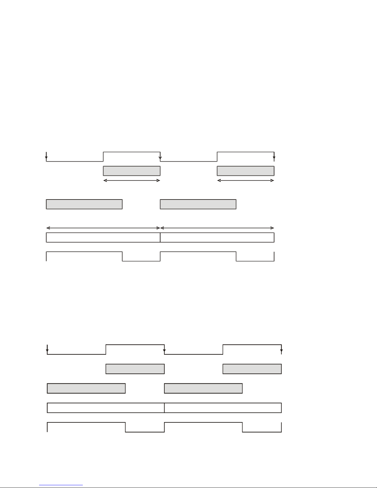
Internally Programmable Frame Rate and Internally Programmable Exposure Time (Default)
Frame Time Frame Time
Readout Time
Readout Time
Exposure Time
Exposure Time
User Exsync
FVAL
Frame Time
Frame Time
Readout Time
Readout Time
Exposure Time
Exposure Time
Programmable
Programmable
Exsync
Programmable
Programmable
FVAL
Frame rate is the dominant factor when adjusting the frame rate or exposure time. When
setting the frame rate, exposure time will decrease, if necessary, to accommodate the new
frame rate. When adjusting the exposure time the range is limited by the frame rate.
Note: The camera will not set frame periods shorter than the readout period.
Camera Features:
• TriggerMode = Off
• AcquisitionFrameRate = 30 (for example)
• ExposureMode = Timed
• ExposureTime = 10000 (for example)
Internally-generated
Figure 12: Internally Programmable Frame Rate and Internally Programmable Exposure Time (Default)
External Frame Rate and External Exposure Time (Trigger Width)
In this mode, EXSYNC sets both the frame period and the exposure time. The rising edge of
EXSYNC marks the beginning of the exposure and the falling edge initiates readout.
Camera Features:
• TriggerMode = On
• ExposureMode = Trigger Width
Camera Operation • 39

Figure 13: External Frame Rate and External Exposure Time (Trigger Width)
Frame Time
Frame Time
Readout Time
Exposure Time
Programmable
FVAL
Exposure Time
Programmable
Internally-generated Exsync
External Frame Rate, Programmable Exposure Time
In this mode, the frame rate is set externally with the falling edge of EXSYNC generating the
rising edge of a programmable exposure time.
Camera Features:
• TriggerMode = On
• ExposureMode = Timed
• ExposureTime = 10000 (for example)
User Exsync
Figure 14: External Frame Rate, Programmable Exposure Time
Exposure Time
Exposure time is the amount of time that the sensor is allowed to accumulate charge before
being read. The user can set the exposure time when the ExposureMode feature is set to
Timed. The limitations on the maximum exposure time are listed below:
• External Exposure Time: 20 µs (min) to 1 second (max).
• Internal Exposure Time: (1 / frame rate) – X
Table 8: Exposure Time Padding
Pixel Size Value of ”X”
8 bits per pixel 50
9 bits per pixel 30
10 bits per pixel 30
Note: The maximum exposure time is dependent on the frame rate. To increase maximum
exposure time, decrease the frame rate.
40 • Camera Operation

Internal Frame Rate
Size)
Size)
The frame rate is dependent on the window size, and the exposure times are dependent on
the frame rate. For example, decreasing the frame rate allows for a longer exposure time.
To increase the frame rate decrease the window size. Frame rate takes priority over
exposure time. Maximum exposure time can be increased by lowering frame rate.
Faster frame rates can be achieved using by decreasing the number of horizontal pixels (x,
columns) and / or the number of vertical lines (y, rows).
The following chart shows maximum camera speed in fps for different combinations of
resolutions aspect ratios and sensor bit depths (input pixel size).
In addition, an online frame rate calculator is available from the Falcon2 product page on
the Teledyne DALSA site, here
Table 9 Maximum Frame rate for 10 Tap Cameralink Configuration
Resolution Aspect
Ratio
12M 4:3 4096 3072 58 58 58
8M 1:1 2816 2816 90 89 66
8M 4:3 3328 2502 86 86 74
4M 1:1 2048 2048 148 122 91
4M 4:3 2432 1728 168 145 108
Maximum
Column
Table 10 Maximum Frame Rate for 8 Tap Cameralink Configuration
Resolution Aspect
Ratio
Maximum
Column
.
Maximum
Rows
Maximum
Rows
Frame Rate
(8 Bit Pixel Size)
Frame Rate
(8 Bit Pixel Size)
Frame Rate
(9 Bit Pixel
Frame Rate
(9 Bit Pixel
Frame Rate
(10 Bit Pixel Size)
Frame Rate
(10 Bit Pixel Size)
12M 4:3 4096 3072 46 46 46
8M 1:1 2816 2816 75 74 57
8M 4:3 3328 2502 71 71 63
4M 1:1 2048 2048 137 122 91
4M 4:3 2432 1728 140 132 101
Camera Operation • 41

I ∕ O Control Category
The Falcon2 I/O controls, as shown by CamExpert, group features used to configure
external inputs and acquisition actions based on those inputs, plus camera output signals to
other devices. Parameters in gray are read only, either always or due to another parameter
being disabled. Parameters in black are user set in CamExpert or programmable via an
imaging application.
Features listed in the description table but tagged as Invisible are usually for Teledyne
DALSA or third party software usage—not typically needed by end user applications.
Figure 15: I / O Category in CamExpert
42 • Camera Operation

Event Control Feature Descriptions
Name
TriggerSelector
Name
TriggerMode
Name
TriggerSource
Name
TriggerSoftware
The following table describes these parameters along with their view attribute and minimum
camera firmware version required. Additionally, the table will indicate which parameter is a
member of the DALSA Features Naming Convention (DFNC), versus the GenICam Standard
Features Naming Convention
Display Name Trigger Selector
Name Space SFNC
Firmware Version 00
Visibility Beginner
Access Read-Only
Type Enumeration
Values FrameStart
Display Name Trigger Mode
Name Space SFNC
Firmware Release 00
Visibility Beginner
Access Read-Write
Type Enumeration
Values On – Use external trigger.
Off - Use internal trigger.
Notes Enables and disables external frame trigger.
Display Name Trigger Source
Name Space SFNC
Firmware Release 00
Visibility Beginner
Access Read-Write
Type Enumeration
Values CC1 – Cameralink Control Line 1
CC2– Cameralink Control Line 2
CC3– Cameralink Control Line 2
CC4– Cameralink Control Line 2
Line1 – General Purpose Input Line 1
Line2– General Purpose Input Line 1
Software- Software trigger
Notes Specifies the internal signal or input line to use as the trigger source. The trigger mode
Display Name Trigger Software
Name Space SFNC
Firmware Release 00
Visibility Beginner
Access Read-Write
Type Command
must be set to On.
Camera Operation • 43

Notes Generate an internal trigger. Available when the trigger mode is enabled and the trigger
Name
TriggerOverlap
Name
TriggerDelay
Name
LineSelector
Name
LineMode
Name
lineName
Display Name Trigger Overlap
Name Space SFNC
Firmware Release 00
Visibility Beginner
Access Read-Only
Type Enumeration
Values Off – No Trigger overlap is allowed.
Notes Specify the type of trigger overlap permitted with the previous frame. This feature defines
Name Space Trigger Delay
Firmware Release SFNC
Visibility 00
Access Beginner
Type Float
Units µs
Values 0 - 281474976710655 µs
Notes
source is equal to ‘Software’.
when a valid trigger will be accepted (or latched) for a new frame.
Specifies the delay in microseconds (μs) to apply after the trigger reception before
activating it.
Display Name Line Selector
Name Space SFNC
Firmware Release 00
Visibility Beginner
Access Read-Write
Type Enumeration
Values CC1, CC2, CC3, CC4 – Cameralink Camera Control Line 1, 2, 3, or 4
Line1, Line2 - General Purpose Input 1 or 2
Line3, Line4 - General Purpose Output 1 or 2
Notes Selects the logical line of the device to configure.
Display Name Line Mode
Name Space SFNC
Firmware Release 00
Visibility Beginner
Access Read-Only
Type Enumeration
Values Input – the line is an input
Output – the line is an output
Notes Specifies if the selected physical pin is used as an input or output signal.
Display Name Line Name
Name Space DFNC
Firmware Release 00
44 • Camera Operation

Visibility Beginner
Name
linePinAssociation
Name
lineDetectionLevel
Name
lineDebouncingPeriod
Access Read-Only
Type Enumeration
Values Input 1, Input 2, Input 3, Input 4, Input 5, Input 6
Output 1, Output 2
Notes Description of the physical pin associate with the logical line.
Display Name Line Pinout
Name Space DFNC
Firmware Release 00
Visibility Beginner
Access Read-Only
Type Enumeration
Values H1_Pin6Pos_Pin5Neg, H1_Pin11Pos_Pin12Neg, H1_Pin3_Pin4, H1_Pin7_Pin8
C1_Pin22Pos_Pin9Neg, C1_Pin10Pos_Pin23Neg, C1_Pin24Pos_Pin11Neg,
C1_Pin12Pos_Pin25Neg
The H1 prefix refers to the Hirose Power and input cable (See Figure 7) while the C1 refers
to the Cameralink 1 connector( See Figure 36 )
Notes Physical pin location associated with the logical line.
Display Name Line Detection Level
Name Space DFNC
Firmware Release 00
Visibility Beginner
Access Read-Write
Type Enumeration
Values Threshold_2_4 - [2.4V] – for TTL inputs
Threshold_6_0- [ 6V] – for 12 V input
Threshold_12_0 – [12V] – for 24 V input
Notes The voltage at which the signal is treated as a logical high. Available when the Line
selector is set to a general purpose input (GPI).
Note: This value is for both general purpose inputs (i.e. setting this value sets it for both
Line 1 and Line 2).
Display Name Line Debouncing Period
Name Space DFNC
Firmware Release 00
Visibility Beginner
Access Read-Write
Type Enumeration
µs
Values 1 to 255 µs
Notes Specifies the minimum length of an input line voltage transition before recognizing a signal
transition. Available when the Line selector is set to an input. Each input line stores its own
debouncing period.
Name LineInverter
Display Name Line Inverter
Camera Operation • 45

Name Space SFNC
Name
LineStatus
Name
LineStatusAll
Name
outputLineSource
Firmware Release 00
Visibility Beginner
Access Read-Write
Type Boolean
Values True – invert signal
False – don’t invert signal
Notes Controls whether to invert the selected input or output line signal.
Display Name Line Status
Name Space SFNC
Firmware Release 00
Visibility Beginner
Access Read-Only
Type Boolean
Values True – the selected signal is high
False – the selected signal is low
Notes Returns the current status of the selected input or output line. This is a polled feature that
Display Name Line Status All
Name Space SFNC
Firmware Release 00
Visibility Beginner
Access Read-Only
Type Integer
Values The order is Line1(LSB), Line2, Line3, Line4, CC1, CC2, ...
Notes Returns the current status of all available line signals, at time of polling, in a single bitfield.
requires the host to poll the camera for the latest value.
7 6 5 4 3 2 1 0
CC4(MSB) CC3 CC2 CC1 Line 4 Line 3 Line 2 Line 1(LSB)
This is a polled feature that requires the host to poll the camera for the latest value.
Display Name Output Line Source
Name Space DFNC
Firmware Release 00
Visibility Beginner
Access Read-Write
Type Enumeration
46 • Camera Operation

Values Off – The output line is open
Name
outputLinePulseDelay
Name
outputLinePulseDuration
SoftwareControlled – The value of the output line is determined by outputLineValue,
outputLineSoftwareLatchControl and/or outputLineSoftwareCmd.
PulseOnStartofInternalEXSYNC – Generate pulse on start of EXSYNC signal to sensor
PulseOnEndOfInternalEXSYNC – Generate pulse on end of EXSYNC signal to sensor
PulseOnStartofExposure – Generate a pulse when the sensor actually starts exposing its
pixels. (Slight delay after EXSYNC)
PulseOnEndofExposure– Generate a pulse when the sensor stops exposing its pixels
PulseOnStartofReadout– Generate a pulse when the sensor starts reading its pixels
PulseOnEndofReadout– Generate a pulse when the sensor stops reading its pixels
PulseOnStartOfLineActive – Generate a pulse when the Line Valid (LVAL) from the sensor
goes active
PulseOnInput1 – Generate a pulse when the CC1 goes active
PulseOnInput2 – Generate a pulse when the CC2 goes active
PulseOnInput3 – Generate a pulse when the CC3 goes active
PulseOnInput4 – Generate a pulse when the CC4 goes active
PulseOnInput5 – Generate a pulse when the General Purpose Input 1 goes active
PulseOnInput6 – Generate a pulse when the General Purpose Input 2 goes active
PulseOnEndOfLineActive – Generate a pulse when the Line Valid (LVAL) from the sensor
goes inactive
Notes Selects which internal signal or software control state to output on the selected line. The
Display Name Output Line Pulse Delay
Name Space DFNC
Firmware Release 00
Visibility Beginner
Access Read-Write
Type Integer
Units µs
Values 0 to 8388608 µs
Notes Sets the delay before the output line pulse duration is output.
pulse is defined by outputLinePulseDelay and outputLinePulseDuration.
Note: the LineMode feature must be set to Output.
Note: LineMode feature must be set to Output and outputLineSource is not equal to Off or
SoftwareControlled.
Display Name Output Line Pulse Duration
Name Space DFNC
Firmware Release 00
Visibility Beginner
Access Read-Write
Type Integer
Units µs
Values 0 to 8388608 µs
Notes Sets the duration of the output pulse.
Note: LineMode feature must be set to Output and outputLineSource is not equal to Off or
SoftwareControlled.
Camera Operation • 47

Name
outputLineSoftwareLatchControl
Display Name Output Line Software Latch Control
Name
outputLineValue
Name
outputLineSoftwareCmd
Name Space DFNC
Firmware Release 00
Visibility Beginner
Access Read-Write
Type Enumeration
Values
Off –
changes to the output line value are applied immediately.
Latch –
changes to the output line value are applied when the Output Line
Software Command is triggered.
Notes The software latch allows the user to set more than 1 output simultaneously
OutputLine that are currently in Software Latch control will only set with the value in
OutputLineValue with the outputLineSoftwareCmd feature.
Display Name Output LineValue
Name Space DFNC
Firmware Release 00
Visibility Beginner
Access Read-Write
Type Enumeration
Values Active - Sets the Output circuit to close.
Inactive - Sets the Output circuit to open.
Notes Selects the state of the output on the selected line. The Value will be applied immediately
if the outputLineSoftwareLatchControl feature is equal to OFF.
The Value will be applied when the outputLineSoftwareCmd feature is set if the
outputLineSoftwareLatchControl feature is equal to LATCH.
Note: LineMode feature must be set to Output and outputLineSource is set
SoftwareControlled.
Display Name Output Line Software Command
Name Space DFNC
Firmware Release 00
Visibility Beginner
Access Read-Write
Type Integer
Values 0 to 3
Notes Contains a bit field representing whether to apply to cached outputLineValue values.
Value
0 Don’t apply any value
1 Apply outputLineValue of Output1
2 Apply outputLineValue of Output2
3 Apply outputLineValue of Output1 and Output2
Note: LineMode feature must be set to Output and outputLineSource is set
SoftwareControlled.
48 • Camera Operation

Name
externalControlledGainMode
Display Name External Gain Mode
Name
externalControlledGainLineActivation
Name
externalControlledGainSampleSource
Name
externalControlledGainMSBSource, externalControlledGainLSBSource
Name Space Custom
Firmware Release 05
Visibility Beginner
Access Read-Write
Type Enumeration
Values Off – disable external line controlled gain
On – enable external line controlled gain
Notes Enables and disables the gain that is controlled by the digital input lines
Display Name External Gain Line Activation
Name Space Custom
Firmware Release 05
Visibility Beginner
Access Read-Write
Type Enumeration
Values FallingEdge – Sample when the source goes low
RisingEdge – Sample when the source goes high
Notes Specifies the signal transition on the source line (externalControlledGainSampleSource)
Display Name External Gain Sample Source
Name Space Custom
Firmware Release 05
Visibility Beginner
Access Read-Write
Type Enumeration
Values CC1, CC2, CC3,CC4, Line1, Line2
Notes Use the selected line to trigger gain sampling. The sampling occurs on the rising or falling
that causes the gain to be sampled.
edge of the signal. This is determined by externalControlledGainLineActivation.
Display Name External Gain [LSB/MSB] Source
Name Space Custom
Firmware Release 05
Visibility Beginner
Access Read-Write
Type Enumeration
Values CC1, CC2, CC3,CC4, Line1, Line2
Camera Operation • 49

Notes Specifies the most and least significant bits that define the externally controlled gain
Name
streamingGPIOLineSelector
Name
streamingGPIO
Name
streamingGPOLineSelector
factor.
MSB LSB Gain Factor
0 0 1x
0 1 2x
1 0 4x
1 1 8x
Invisible Features
Name Space Custom
Firmware Release 04
Visibility Invisible
Notes Internal use. To implement feature streaming.
Name Space Custom
Firmware Release 04
Visibility Invisible
Notes Internal use. To implement feature streaming.
Name Space Custom
Firmware Release 04
Visibility Invisible
Notes Internal use. To implement feature streaming.
Trigger Modes
The camera’s image exposures are initiated by a trigger signal The trigger event is either a
programmable internal signal used in free running mode, an external input used for
synchronizing exposures to external triggers, or a programmed function call message by the
controlling computer. These triggering modes are described below.
• Free running (trigger disabled): The camera free-running mode has a programmable
internal timer for frame rate and a programmable exposure period.
• External trigger: Exposures are controlled by an external trigger signal. The external
trigger signal can be either a Camera Link control line (i.e. CC [4 : 1]) or a general
purpose input (e.g. GPIO [2 : 1]. General purpose inputs are isolated by an optocoupler input with a time programmable debounce circuit.
• Software trigger: An exposure trigger is sent as a control command via the Camera
Link serial communications interface. Software triggers cannot be considered time
accurate due to communications latency and sequential command jitter.
I/O Block Diagram
The following diagram describes the Input/Output features of the camera and how they are
related.
50 • Camera Operation

Figure 16 I/O Module Block Diagram
CameraLink Control Lines
Falcon2 can use the four CameraLink control lines to trigger frames or output pulses. These
signals are located in the CameraLink 1 cable (See Appendix A: Camera Link) and bypass
the Line detection level.
Opto-coupled Inputs
Falcon2 provides two sets of Opto-isolated input signals. These can be used as external
trigger sources. The signals should be in range from 2.4 V to 24 V, 5 V typical. See
lineDetectionLevel.
The delay between signals at the I/O pin and the internal timing core is a function of the
signal swing and the typical latency @ 5V swing is 3.5 µs.
Refer to Figure 7: 12-pin Hirose Circular Male Power Plug—Power Connector for the
connector pin out and electrical information. The cable shell and shield should electrically
connect the camera chassis to the computer chassis for maximum EMI protection.
Camera Operation • 51

Figure 17 Opto-Coupled Input
Each input incorporates a signal debounce circuit (following the opto-coupler) to eliminate
short noise transitions that could incorrectly be interpreted as a valid pulse. The duration is
user programmable from 1 µs to 255 µs using CamExpert.
Opto-Coupled Outputs
The outputs are unpowered devices and require external power. The simplified diagram
below demonstrates the need for a pull-up resistor when using the outputs.
Figure 18: Simplified General Purpose Output Diagram
Advanced Processing Control Category
The Falcon2 Advanced Processing controls, as shown by CamExpert, groups parameters
used to configure Defective Pixel Detection, Flat Field calibration. Parameters in gray are
read only, either always or due to another parameter being disabled. Parameters in black
are user set in CamExpert or programmable via an imaging application.
Note that the features listed in the description table but tagged as Invisible are usually for
Teledyne DALSA Support or third party software usage—and not typically required by enduser applications.
52 • Camera Operation

Figure 19 Advanced Processing Control
Camera Operation • 53

Advanced Processing Control Feature Descriptions
Name
flatfieldCorrectionMode
Name
flatfieldCorrectionAlgorithm
Name
flatfieldCorrectionGainMode
The following table describes these parameters along with their view attribute and the
minimum camera firmware version required.
Display Name Flat field Correction Mode
Name Space DFNC
Firmware Release 00
Visibility Beginner
Access Read/Write
Type Enumeration
Values Off - Flat Field correction disabled
Notes Sets the mode for the flatfield correction.
Display Name Flat field Correction Algorithm
Name Space DFNC
Firmware Release 00
Visibility Expert
Access Read Only
Type Enumeration
Values Method1(monochrome camera)
Notes The following formula is used to calculate the flatfield corrected pixel:
ActiveAll - FPN and PRNU correction is active
ActiveFPNOnly - FPN correction is active
ActivePRNUOnly - PRNU correction is active
Calibration - The camera is configured to calibration mode(Only available when
TriggerMode=Off, flatfielCorrectionCurrenActiveSet is not FactoryFlatfield, and width and
height are maximized). The device may automatically adjust some features in the camera
when calibration mode is enabled. The features that are automatically adjusted are device
specific. The device will not restore these features when the flat field correction mode is
changed from calibration mode to another mode. For example, width and height may be set
to the maximum sensor size when the flat field calibrate mode is enable.
Method2(color camera)
Mono camera:
newPixelValue
= (sensorPixelValue
x,y
– FFCOffset
x,y
) * FFCGain
x,y
[x][y]
Color camera:
newPixelValue
= (sensorPixelValue
x,y
– FFCOffset
x,y
) * FFCGain
x,y
* gain per color
x,y
Display Name Gain Correction Mode
Name Space Custom
Firmware Release 05
Visibility Expert
Access Read Only
Type Enumeration
Values HighGain -The set was calibrated using high gain and lower resolution
HighResolution - The set was calibrated using high resolution and lower gain
Notes Displays the flatfield gain mode that will was used in calibration.
High gain mode can apply a correction gain between 1 and 2 with reduced (9 bit) resolution.
High resolution can apply a correction gain between 1 and 1.5 with maximum (10 bit)
resolution
Refreshes when flatfieldCorrectionCurrentActiveSet, flatfieldCalibrationPRNU,
flatfieldCalibrationClearCoefficient, or flatfieldCoefficientsCopyInCurrent changes.
54 • Camera Operation

Name
flatfieldCorrectionType
Display Name Correction Type
Name
flatfieldCorrectionCurrentActiveSet
Name
flatfieldCorrectionPixelYCoordinate
Name
flatfieldCorrectionPixelXCoordinate
Name
flatfieldCorrectionGain
Name Space DFNC
Firmware Release 00
Visibility Expert
Access Read Only
Type Enumeration
Values AreaBase
Notes Flatfield correction is based on an entire image (array).
Display Name Current Active Set
Name Space DFNC
Firmware Release 00
Visibility Expert
Access Read-Write (Read-Only when in Calibration Mode)
Type Enumeration
Values FactoryFlatfield - Factory calibrated flat field. This set actual consists of three sets calibrated
Notes Specifies the current set of flat field coefficients to use. This feature cannot be changed while
for a given pixelInputSize. When the pixelInputSize changes, the camera will automatically
change the set in use.
UserFlatField1 to UserFlatField4 - User configurable flat field sets. They can only be calibrated
to 1 pixelInputSize value.
the camera is in flat field calibration mode.
Display Name Pixel Y Coordinate
Name Space DFNC
Firmware Release 00
Visibility Expert
Access Read-Write when in Calibration Mode
Type Enumeration
Values 1 to SensorHeight
Notes Vertical Indexer into the array of FFC coefficients.
Display Name Pixel X Coordinate
Name Space DFNC
Firmware Release 00
Visibility Expert
Access Read-Write when in Calibration Mode
Type Enumeration
Values 1 to SensorWidth
Notes Horizontal Indexer into the array of FFC coefficients.
Display Name Pixel Gain(PRNU)
Name Space DFNC
Firmware Release 00
Visibility Beginner
Access Read-Write when in Calibration Mode
Camera Operation • 55

Type Float
Name
flatfieldCorrectionOffset
Name
flatfieldCalibrationClearCoefficient
Name
flatfieldCalibrationSampleSize
Name
flatfieldCalibrationFPN
Name
flatfieldCalibrationTarget
Values 1 to 2 (when flatfieldCorrectionGainMode = HighGain).
Notes Sets the gain to apply to the currently selected pixel.
Display Name Pixel Offset(FPN)
Name Space DFNC
Firmware Release 00
Visibility Beginner
Access Read-Write when in Calibration Mode
Type Integer
Values 0 to 127
Notes Sets the offset to apply to the currently selected pixel.
Display Name Clear Coefficients
Name Space DFNC
Firmware Release 00
Visibility Expert
Access Read-Write when in Calibration Mode
Type Command
Notes This feature is used to clear all the current FPN and PRNU coefficients in the selected Active
1 to 1.5 (when flatfieldCorrectionGainMode = HighResolution).
Set.
Display Name Calibration Sample Size
Name Space DFNC
Firmware Release 00
Visibility Beginner
Access Read-Only
Type Integer
Values 64
Notes The number of images to average to perform the calibration.
Display Name Offset(FPN) Calibration
Name Space DFNC
Firmware Release 00
Visibility Expert
Access Read-Write when in Calibration Mode
Type Command
Notes Performs fixed pattern noise (FPN) calibration. FPN calibration eliminates fixed pattern noise
Display Name Gain Calibration Target
Name Space DFNC
Firmware Release 00
Visibility Expert
Access Read-Write when in Calibration Mode
by subtracting all non-uniformities and dark current to obtain near 0 DN output in the dark
(no light exposed to the sensor).
56 • Camera Operation

Type Float
Name
flatfieldCalibrationPRNU
Name
flatfieldCalibrationGainMode
Name
flatfieldCalibrationSave
Name
flatfieldCoefficientsCopySource
Name
flatfieldCoefficientsCopyInCurrent
Units %
Values 0 to 100
Notes Sets the target pixel value for the gain (PRNU) calibration. It is specified as a percentage of
Display Name Gain(PRNU) Calibration
Name Space DFNC
Firmware Release 00
Visibility Expert
Access Read-Write when in Calibration Mode
Type Command
Notes Performs photo response non-uniformity (PRNU) calibration.. PRNU calibration eliminates the
Display Name Gain Calibration Mode
Name Space Custom
Firmware Release 05
Visibility Guru
Access Read-Write when in Calibration Mode
Type Enumeration
Values HighGain - Calibrate using high gain and lower resolution
Notes Selects the flatfield gain mode that will be used in calibration.
the output range (for example, 1023 DN for 10 bits).
difference in responsivity between the most and least sensitive pixel, creating a uniform
response to light. See the Gain (PRNU) Calibration section in
Calibration Algorithms.
HighResolution - Calibrate using high resolution and lower gain
High gain mode can apply a correction gain between 1 and 2 with reduced resolution.
High resolution can apply a correction gain between 1 and 1.5 with maximum resolution.
Appendix D: Internal Flat Field
Display Name Save Calibration
Name Space DFNC
Firmware Release 00
Visibility Expert
Access Read-Write when in Calibration Mode
Type Command
Notes Saves the current flat field coefficients in the Active Set.
Display Name Copy Source
Name Space DFNC
Firmware Release 00
Visibility Expert
Access Read-Write when in Calibration Mode
Type Enumeration
Values FactoryFlatfield - Factory Calibrated flatfield.
UserFlatField1 to UserFlatField4 - User configurable flat field sets.
Notes Selects the flatfield coefficients set to copy to the current Active Set
Display Name Copy Coefficient to Active
Camera Operation • 57

Name Space DFNC
Name
flatfieldCorrectionPixelReplacementThreshold
Name
flatfieldCorrectionPixelReplacementMode
Name
flatfieldCorrectionPixelReplacementAlgorithm
Corrected
“Hot” Pixels Replaced
0
(
flatfieldCorrectionPixelReplacementThreshold
)
Flat Field Offset(FPN) Values
Offset(FPN) Correction
127
64
32
96
Firmware Release 00
Visibility Expert
Access Read-Write when in Calibration Mode
Type Command
Notes Copies the currently selected flat field coefficients in the Active Set.
Display Name Pixel Replacement Threshold
Name Space Custom
Firmware Release 00
Visibility Guru
Access Read-Write
Type Integer
Values 1 to 127
Notes The FFC offset value (FPN) above which pixel replacement occurs (See Figure 20). This value
can be adjusted to replace more or fewer pixels.
Figure 20 Pixel Replacement Threshold
Display Name Pixel Replacement Mode
Name Space Custom
Firmware Release 05
Visibility Expert
Access Read-Write
Type Enumeration
Values Off - Disable pixel replacement
Active - Enable defective pixel replacement
Notes Enable or disable pixel replacement.
If Active: If FPN
Pixel
= (Pixel
x,y
> flatfieldCorrectionPixelReplacementThreshold OR PRNU
x,y
x+1,y
+ Pixel
) / 2 ' replace
x-1,y
Display Name Pixel Replacement Algorithm
Name Space DFNC
Firmware Release 05
Visibility Expert
Access Read-Only
Type Enumeration
> 510, then
x,y
58 • Camera Operation

Values Method1 (Average/Copy Adjacent) – the algorithm consists of averaging the adjacent pixels
Name
flatfieldCalibrationPixelReplacement
Name
flatfieldCalibrationPixelReplacementOffsetThreshold
when replacing a single defect and copying the nearest pixel when replacing two consecutive
defects or a defect at the beginning or end of a line, i.e.
A= pixel A
B= pixel B
X= defect
AXB is corrected to ACB where:
C= (A+B)/2
AXXB is corrected to AABB
XA is corrected to AA
BX is corrected to BB
Method3 (Average/Weighted Average) is a custom enumeration. algorithm consists of
averaging the adjacent pixels when replacing a single defect and performing a weighted
average when replacing two consecutive defects. A defect at the beginning or end of a line
is not corrected, i.e.
A= pixel A
B= pixel B
X= defect
AXB is corrected to ACB where:
C= (A+B)/2
AXXB is corrected to ACDB where
C = (11 *A + 5*B)/16
D = (5*A + 11*B)/16
XA is not corrected
BX is not corrected
Notes Selects the pixel replacement algorithm.
Display Name Pixel Replacement Calibration
Name Space Custom
Firmware Release 05
Visibility Guru
Access Read-Write when flatfieldCorrectionMode = "Calibration"
Type Command
Notes Performs pixel defects calibration. This is a cumulative function (i.e. defects are added to the
current defect map).
For each pixel:
If ABS (AveragedDarkValue
then FPN
= 127 ' mark as bad
x,y
- FPN
x,y
) > flatfieldCalibrationPixelReplacementOffsetThreshold
x,y
Display Name Pixel Replacement Calibration Threshold
Name Space Custom
Firmware Release 05
Visibility Guru
Access Read-Write when flatfieldCorrectionMode = Calibration
Type Integer
Values 1 to 127
Notes Specifies the offset (FPN) value above which the pixel is marked as defective.
Camera Operation • 59

Name
flatfieldCalibrationPixelReplacementGainThreshold
Display Name Pixel Replacement Calibration Threshold
Name
flatfieldCalibrationHotPixelsReplaced
Name
flatfieldCalibrationUncorrectableHotPixels
Name
flatfieldCalibrationDeadPixelsReplaced
Name Space Custom
Firmware Release 05
Visibility Guru
Access Read-Write when flatfieldCorrectionMode = "Calibration"
Type Float
Values 1.5 to 9 (when flatfieldCalibrationGainMode = High Resolution)
2 to 17 (when flatfieldCalibrationGainMode = High Gain)
Notes Specifies the gain (PRNU) value, above which the pixel is marked as defective. Only used in
Display Name Hot Pixels Replaced
Name Space Custom
Firmware Release 05
Visibility Guru
Access Read-Only
Type Integer
Values 0 to (Width * Height)
Notes Displays the number of hot pixels (i.e. with uncorrectable FPN) that have been replaced.
calibration.
Use flatfieldCalculatePixelStatistics to calculate this value.
Display Name Uncorrectable Hot Pixels
Name Space Custom
Firmware Release 06
Visibility Guru
Access Read
Type Integer
Values 0 to (Width * Height)
Notes Reports the number of hot pixels (i.e. with uncorrectable FPN) that can not replaced. The
Display Name Dead Pixels Replaced
Name Space Custom
Firmware Release 05
Visibility Guru
Access Read
Type Integer
Values 0 to (Width * Height)
Notes Displays the number of dead pixels (i.e. with uncorrectable PRNU) that have been replaced
camera cannot correct any more than two horizontally adjacent pixels (i.e. only the pixels on
the ends of a horizontal cluster will get corrected) .
Note: Hot Pixels and dead pixel will interact. For example if there are 2 hot pixels in a row,
followed by a dead pixel, then the middle hot pixel will be uncorrectable.
Use flatfieldCalculatePixelStatistics to calculate this value.
Use flatfieldCalculatePixelStatistics to calculate this value.
60 • Camera Operation

Name
flatfieldCalibrationUncorrectableDeadPixels
Display Name Uncorrectable Dead Pixels
Name
flatfieldCalibrationOffsetPixelsClipped
Name
flatfieldCalibrationDeadPixelsNotReplaced
Name
flatfieldCalibrationGainPixelsClipped
Name Space Custom
Firmware Release 06
Visibility Guru
Access Read
Type Integer
Values 0 to (Width * Height)
Notes Reports the number of dead pixels (i.e. with uncorrectable PRNU) that cannot be replaced.
Display Name Offset Pixels Clipped
Name Space Custom
Firmware Release 05
Visibility Guru
Access Read-Only
Type Integer
Values 0 to (Width * Height)
Notes Displays the number of pixels that have an FPN coefficient of 0. This can be result of setting
The camera cannot correct any more than two horizontally adjacent pixels (i.e. only the
pixels on the ends of a horizontal cluster will get corrected) .
Note: Hot Pixels and dead pixel will interact. For example if there are 2 hot dead in a row,
followed by a hot pixel, then the middle dead pixel will be uncorrectable.
Use flatfieldCalculatePixelStatistics to calculate this value.
the black offset value too high.
Display Name Dead Pixels NOT Replaced
Name Space Custom
Firmware Release 05
Visibility Guru
Access Read-Only
Type Integer
Values 0 to (Width * Height)
Notes Displays the number of dead pixels (i.e. with uncorrectable PRNU) that have been set to the
Display Name Gain Clipped Pixels
Name Space Custom
Firmware Release 05
Visibility Guru
Access Read-Only
Type Integer
Values 0 to (Width * Height)
Notes Specifies the number of pixels that have a correction factor of less than 1. If this number is
maximum gain but not replaced. This would include any pixel value that exceeds the
maximum gain (i.e. either 1.5 or 2, depending on flatfieldCalibrationGainMode) but less than
flatfieldCalibrationPixelReplacementGainThreshold.
too high, it means that the Gain target is set too low.
Camera Operation • 61

Name
flatfieldCalculatePixelStatistics
Display Name Calculate Pixel Statistics
Name
defectivePixelDetectionAlgorithmSelector
Name
defectivePixelDetectionMode
Name
defectivePixelDetectionMinBrightThreshold
Name
simpleFeedThroughCoeff1, simpleFeedThroughCoeff2, simpleFeedThroughCoeff3
Name Space Custom
Firmware Release 06
Visibility Guru
Access Read-Write
Type Command
Values
Notes This command calculates the pixel statistics.
Display Name Dynamic Replacement Algorithm
Name Space Custom
Firmware Release 05
Visibility Expert
Access Read-Write
Type Enumeration
Values Method3 (Pre-Correction Median Filter) - Horizontal Median Filter. Before FFC Correction.
Method4 (Post-Correction Median Filter) - Horizontal Median Filter. After FFC Correction.
Notes Enables or disables dynamic defective pixel detection and replacement. Note that each filter
can be active at the same time.
Display Name Dynamic Replacement Mode
Name Space DFNC
Firmware Release 05
Visibility Expert
Access Read-Write
Type Enumeration
Values Active - Enable dynamic defective pixel replacement.
Off - Disable dynamic defective pixel replacement.
Notes Enables or disables the dynamic defective pixel detection and replacement for the selected
algorithm.
If (ABS (Pixel
Pixel
Pixel
) ) > defectivePixelDetectionMinBrightThreshold ) THEN Pixel
x+1, y
, Pixel
x,y ,
x,y
x+1,y
- Pixel
)
> defectivePixelDetectionMinBrightThreshold AND ABS ( Pixel
x-1,y)
= Median (Pixel
x,y
x,y
x-1,y
Note: both the Pre and Post filters can be active at the same time.
,
Display Name Dynamic Replacement Min Threshold
Name Space DFNC
Firmware Release 05
Visibility Guru
Access Read-Write
Type Integer
Values 1 to 255
Notes Defines the maximum threshold value that a pixel can achieve before being corrected.
Display Name Simple Feedthrough Correction Coeff 1 - Coeff 3
62 • Camera Operation

Name Space Custom
Name
feedThroughCorrectionMode
Name
flatfieldAlgorithmBufferFormat
Name
flatfieldAlgorithmBufferWidth
Name
flatfieldAlgorithmBufferHeight
Name
flatfieldAlgorithmGainDivisor
Firmware Release 00
Visibility Guru
Access Read-Write
Type Integer
Values -127 to 127
Notes Retrieves and sets the simple feed through correction coefficient.
Display Name Feed Through Correction Apply
Firmware Release 00
Name Space Custom
Visibility Guru
Access Read-Write
Type Enumeration
Values Off - Disable feedthrough correction
Notes Apply the feed through correction.
On - Enable feedthrough correction
Invisible Features
Name Space DFNC
Firmware Release 05
Visibility Invisible
Access Read Only
Type Enumeration
Values Mono8
Notes Each flat field coefficient is stored as an 8 bit number. This feature is used for Sapera FFC
support.
Name Space DFNC
Firmware Release 05
Visibility Invisible
Access Read Only
Type Integer
Values SensorWidth
Notes The width of the flat field correction buffer in pixels. Used for Sapera FFC Support.
Name Space DFNC
Firmware Release 05
Visibility Invisible
Access Read Only
Type Integer
Values SensorHeight
Notes The height of the flat field correction buffer in pixels. Used for Sapera FFC Support.
Name Space DFNC
Camera Operation • 63

Firmware Release 05
Name
flatfieldAlgorithmGainBase
Name
flatfieldAlgorithmOffsetMax
Name
flatfieldAlgorithmOffsetMin
Name
flatfieldAlgorithmOffsetFactor
Name
flatfieldAlgorithmGainMax
Visibility Invisible
Access Read Only
Type Integer
Values 512
Notes The camera uses this value to calculate the FFC gain factor. Used for Sapera FFC Support.
Name Space DFNC
Firmware Release 05
Visibility Invisible
Access Read Only
Type Integer
Values 1
Notes The off camera uses this value to calculate the FFC gain factor. Used for Sapera FFC
Name Space DFNC
Firmware Release 05
Visibility Invisible
Access Read Only
Type Integer
Values 126
Notes The maximum valid offset coefficient value. Used for Sapera FFC Support.
This is equivalent to the high gain setting with the in-camera calibration. In other words
when you calibrate the camera in the host, it can only be a High Gain PRNU calibration. See
formula.
Support. See formula.
Name Space DFNC
Firmware Release 05
Visibility Invisible
Access Read Only
Type Integer
Values 1
Notes The minimum valid offset coefficient value. Used for Sapera FFC Support.
Name Space DFNC
Firmware Release 05
Visibility Invisible
Access Read Only
Type Integer
Values 1.0
Notes The multiplier applied to the FFC offset values. Used for Sapera FFC Support. See formula
Name Space DFNC
Firmware Release 05
Visibility Invisible
Access Read Only
64 • Camera Operation

Type Integer
Name
flatfieldAlgorithmGainMin
complexFeedThroughCoeff3
Values 510
Notes The maximum valid gain coefficient value. Used for Sapera FFC Support.
Name Space DFNC
Firmware Release 05
Visibility Invisible
Access Read Only
Type Integer
Values 0
Notes The minimum valid gain coefficient value. Used for Sapera FFC Support.
Name complexFeedThroughCoeff1, complexFeedThroughCoeff2,
Display Name Complex Feedthrough Correction Coeff 1 - Coeff 3
Firmware Release 00
Name Space Custom
Visibility Invisible
Access Read-Write
Type Integer
Values -127 to 127
Notes Gets and sets the simple feed through correction coefficient. For internal use.
Camera Operation • 65

Flat Field Correction and Defective Pixel Detection Overview
The Flat Field correction function consists of using two coefficients per pixel which correct
the gain and offset of the corresponding pixel. These corrections compensate for the Photoresponse Non-uniformity (PRNU) and Fixed Pattern noise (FPN) attributes unique to each
camera sensor. In addition, the camera supports replacement of defective pixels (hot, dead,
blinking) with a value based on neighborhood pixels.
Correction Function Block Diagram
The following simplified block diagram shows the processing chain that is applied to the
image data (the flat field and defective pixel blocks are highlighted). Note that each
processing block can be activated and deactivated independently. For example, the FPN and
PRNU coefficients can be applied independently or together using the
flatfieldCorrectionMode.
Figure 21 Flat field and defective pixel processing
Flat Field Correction Algorithm Description
Flat Field Correction Algorithm–Method1 (feature: flatfieldCorrectionAlgorithm) applies the
following FFC formula for correcting pixel values:
newPixelValue
= (sensorPixelValue
x,y
where:
• x & y are the Flat Field Correction Pixel coordinates.
• See the flatfieldCorrectionPixelXCoordinate and flatfieldCorrectionPixelYCoordinate
features.
• newPixelValue is the pixel value after Flat Field Correction is applied.
• sensorPixelValue is the pixel value before Flat Field correction is applied.
• FFCOffset is the offset coefficient value to subtract from the sensorPixelValue.
• FFCGain is the gain coefficient value that is multiplied with the sensorPixelValue.
The implementation of this formula requires that both the FPN and PRNU coefficient are
stored in 16 bits. For the Falcon2 we reserve 7 bits for the FFCOffset (FPN) coefficient and 9
bits for the FFCGain (PRNU) coefficient. The FFCGain can be calculated as follows:
FFCGain
= (FFCGainRaw
x,y
where:
• x & y are the Flat Field Correction Pixel coordinates.
• FFCGain is the floating point multiplier of the sensorPixelValue.
• FFCGainRaw is the stored 9 bit value representing the FFC gain value.
– FFCOffset
x,y
/ GainDivisor) + 1.0
x,y
x,y
) * FFCGain
x,y
66 • Camera Operation

• GainDivisor is either 512 or 1024 depending on whether the camera was calibrated
in High resolution or high gain mode. See flatfieldCalibrationGainMode and
flatfieldCorrectionGainMode.
General Notes on FFC calibration
The camera comes calibrated with three factory sets, one for each sensor bit depth. These
sets switch automatically when the user changes pixelSizeInput. In addition to the factory
calibrations, the camera provides four user configurable FFC sets. These can be calibrated
and saved in the camera. For more information on this, see “How to do an FFC Setup in the
Camera”.
Another option is to perform the flat field correction in the frame grabber. See the section
How to do a FFC Setup via Sapera CamExpert for more information.
In either case, we recommend that you repeat the correction when a temperature change of
greater than 10 °C occurs.
For best results, ensure that:
1. Gain (PRNU) calibration has a clean, white reference. The quality of this reference is
important for proper calibration. White paper is often not sufficient because the grain
in the white paper will distort the correction. White plastic or white ceramic will lead
to better balancing.
2. Ambient light flicker (e.g. fluorescent lights) is sufficiently low not to affect camera
performance and calibration results.
3. The average pixel should be at least 20 % below the target output. If the target is
too close, then some pixels may not be able to reach full swing due to correction
applied by the camera.
4. When 6.25 % of pixels from a single row within the region of interest are clipped, flat
field correction results may be inaccurate.
5. Correction results are valid only for the current black offset values. If you change
this value, it is recommended that you recalculate your coefficients.
An important note on window blemishes:
When flat field correction is performed, window cleanliness is paramount. The figure below
shows an example of what can happen if a blemish is present on the sensor window when
flat field correction is performed. The blemish will cast a shadow on the wafer. FFC will
compensate for this shadow by increasing the gain. Essentially FFC will create a white spot
to compensate for the dark spot (shadow). As long as the angle of the incident light remains
unchanged then FFC works well. However when the angle of incidence changes significantly
(i.e. when a lens is added) then the shadow will shift and FFC will makes things worse by
not correcting the new shadow (dark spot) and overcorrecting where the shadow used to be
(white spot). While the dark spot can be potentially cleaned, the white spot is an FFC
artefact that can only be corrected by another FFC calibration.
Camera Operation • 67

Figure 22. Spectral distribution of light source used during calibration of color cameras only. This corresponds roughly to a 5200
K color temperature.
How to do an FFC Setup in the Camera
CamExpert has a default timeout of 20 seconds per command, which is too
short for the FFC calibration to run fully. You can change the default timeout by
setting a command line argument in the short-cut:
• Right click on the short-cut in the start menu and select properties.
• Add –timeout 60 to increase the command timeout to 60 seconds (See
below)
• Repeat for desktop short-cut
Figure 23: Setting the camera’s timeout value
The calibration is performed in two steps. The fixed offset (FPN) is determined first by
performing an averaging without any light. This calibration determines exactly how much
offset to subtract per pixel in order to obtain flat output when the sensor is not exposed.
68 • Camera Operation

If the camera is run at exposure time that is significantly higher than the calibration
exposure, an additional Pixel Replacement Calibration may be require
The gain (PRNU) calibration is performed next to determine the multiplication factors
required to bring each pixel to the required value (target) for flat, white output. For the
monochrome cameras, the target is determined by the user (See flatfieldCalibrationTarget).
The color camera requires a separate target for each color which is calculated as 23 %
higher than the average pixel for the given color.
It is important to do the FPN correction first. Results of the FPN correction are used in the
PRNU procedure.
Let’s work through a flat field calibration example:
1. The camera is placed in internal exposure and frame rate. Make sure that the
area of interest (AOI) is set to the full window (i.e. Width=SensorWidth and
Height=SensorHeight). No other exposure mode or AOI configuration will allow FFC
calibration. See ExposureMode, TriggerMode, OffsetX, OffsetY, Width, Height.
2. Settings such as frame rate, exposure time, etc. are set as close as possible to the
actual operating conditions. Set system gain to 1 and background subtract to 0,
as these are the defaults during FFC calibration. See GainSelector, Gain,
BlackLevelSelector, and BlackLevel.
3. Select correction active set to user flat field 1. Go to flat field correction
mode, select calibration. See flatfieldCorrectionCurrentActiveSet, and
flatfieldCorrectionMode.
4. Clear existing coefficients. See flatfieldCalibrationClearCoefficient.
5. Place the camera in the dark (i.e. cover lens) and run FPN calibration. This
performs the FPN correction and saves the FPN coefficients to temporary memory.
See flatfieldCalibrationFPN.
6. Calibration mode enables both FPN and PRNU correction. Verify signal output is close
to 0 DN.
7. Illuminate the sensor to 65 % saturation, using a high quality white reference.
8. Set flat field target to 80 % saturation (monochrome only). See
flatfieldCalibrationTarget.
9. Select Gain Calibration Mode as either High Gain or High Resolution
10. Run Gain (PRNU) calibration. See flatfieldCalibrationPRNU.
11. [Optional] Set the exposure time to {X % longer than} the longest value that will be
required by the user’s system. Set the pixel replacement calibration threshold to 60.
Run pixel replacement calibration. See “Hot Pixels and Long Exposure Times” for
more information about why this is necessary. See ExposureTime,
flatfieldCalibrationPixelReplacementThreshold and,
flatfieldCalibrationPixelReplacement
12. Save the flat field calibration: flatfieldCalibrationSave.
Here is the factory calibration procedure for the 8M camera:
1. The camera is placed in full internal, 8 taps, 10 bits, active window (3328 x 2816,
only available to factory), system gain 1, color gain 1, background subtract 0, global
FPN calibrated such that dark FPN is 30 DN (10 bit) 50 fps, 1500 µs exposure. For
color, use 20 fps, 25000 µs exposure. This last part is important (mono: 50 fps,
1500 µs exposure. Color: 20fps 25000 µs exposure) and ensures that the camera is
in non-concurrent mode. In non-concurrent mode, readout and integration do not
overlap thus eliminating some residual artefacts.
Camera Operation • 69

2. The camera is placed in the dark and FPN Calibration is run.
3. With FPN correction on the sensor is illuminated (Light Source: Broadband Quartz
Halogen, 3250 K, with a 750 nm cut-off filter) with a light level of 26.4 µW/cm
BPP). This ensures each camera will have the same responsivity since the light level
and target value are always the same. Typical output levels for the camera at this
light level are 680 DN (10 bit).
4. The sensor window at this point has been cleaned thoroughly such that there are no
significant blemishes present.
5. For the monochrome camera only, PRNU target is set to 840 DN (82.11 % peak).
6. PRNU calibration is run.
How can one match gain and offset values on multiple cameras?
One way is of course to use flat field correction. All cameras would be set up under the
same conditions, including lighting, and then calibrated with FPN and PRNU. This process
can be time-consuming and complicated (especially the white target). Another way is to use
global FPN (Sensor Control > Black Level Selector > DigitalAll1):
1. Starting from factory settings (factory flat field), take note what the highest dark
offset is among the set of cameras. If the highest dark offset is higher than about 16
DN (10 bit) you might want to consider recalibrating the FPN correction. You can use
the histogram feature in CamExpert to determine this value see Figure 24. Large
differences in dark offset between the factory and user are typically caused by
differences in temperature from factory to user. Large dark offsets will result in
PRNU-correction-induced FPN and should therefore be avoided.
2. Decrease global FPN (increase the offset in dark) on all cameras until they are the
same and reach at least 4 DN (10 bit).
3. Illuminate to about 80 % saturation (820 DN, 10 bit) and note the highest signal
level among the set of cameras.
4. Increase the system gain (Sensor Control > Gain Selector > DigitalAll1) on the
cameras until they all reach the same output level (highest of all cameras).
5. Place camera in the dark and repeat step 2 to 4 until both dark offset and 80 % sat
signal levels are equal on all cameras.
2
(10
Hot Pixels and Long Exposure Times
The camera is calibrated and optimized for an exposure time of 1500 microseconds
providing peak FPN and PRNU performance are at this setting. This FPN correction also
manages hot pixels for the same exposure time. Changing the exposure time to very long
times, such as 60000 microseconds, can introduce additional uncorrected hot pixels in the
image. The user can eliminate these pixels by performing a user pixel replacement
calibration which will capture and correct these pixels. This correction eliminates hot pixels
at long exposure time while maintaining the same FPN characteristics.
How to do a FFC Setup via Sapera CamExpert
The Sapera LT CamExpert tool provides an easy GUI based method for a user to perform a
Flat Field Calibration. The process first requires the user to plan acquisitions in dark and
bright conditions, followed by the FFC process itself. Please review the list of best practices
in the Gener al N ot es on FF C cal i br at ion section. The steps to perform a FFC calibration using
CamExpert are detailed below.
Verify a dark acquisition
70 • Camera Operation

Close the camera lens iris and cover the lens with a lens cap. Using CamExpert, click on the
Important: In this example, the average pixel value for the frame is close to black.
dynamic range specified for that sensor).
grab button and then the histogram button. The following figure shows a typical histogram
for a Falcon2 grabbing a very dark image.
Figure 24 CamExpert histogram of a dark scan (8 bit output)
Also note that most sensors will show a much higher maximum pixel value due
to one or more "hot pixels". The sensor specification accounts for a small
number of hot or stuck pixels (pixels that do not react to light over the full
Verify bright image
Aim the camera at the PRNU reference. Using CamExpert, click on the grab button and then
the histogram button. Use the lens iris to adjust for a bright gray approximately around a
pixel value of 200 (for 8-bit pixels). The following figure shows a typical histogram for a
Falcon2 grabbing a bright gray image.
Camera Operation • 71

Important: In this example, the average pixel value for the frame is bright gray.
that do not react to light over the full dynamic range specified for that sensor).
Also note that sensors may show a much higher maximum or a much lower
minimum pixel value due to one or more "hot or dead pixels". The sensor
specification accounts for a small number of hot, stuck, or dead pixels (pixels
Once the bright gray acquisition setup is done, note the camera position and lens iris
position so as to be able to repeat it during the calibration procedure.
Start the flat field calibration tool via the CamExpert menu bar
Pre-processing > Flat Field Correction > Calibration.
The Flat Field calibration window provides a three step process to acquire two reference
images and then save the flat field correction data for the camera used. To aid in
determining if the reference images are valid, a histogram tool is provided so that the user
can review the images used for the correction data. Note that it is important to follow the
instructions in the preceding section to prepare for the dark and light acquisition steps
required for calibration.
72 • Camera Operation

1. Click on the Advanced Setting button to change the default number of frames averaged
for each calibration step. The default value is 10 frames (as performed by
CamExpert).
Camera Operation • 73

2. Setup the camera to capture a uniform dark image. Black paper with no illumination
and the camera lens’ iris closed to minimum can provide such a dark image. Or cover
the lens with a black lens cap.
3. Click on Acquire Black Image. The flat field calibration tool will grab video frames,
analyze the pixel gray level spread, and present the statistics. The desired black
reference image should have pixel values less then 20. If the results are acceptable,
accept the image as the black reference.
4. Setup the camera to acquire a uniform white image (but not saturated white). Even
illumination on white paper can be used, with a gray level of minimum of 128 (8-bit
mode). It is preferable to prepare for the white level calibration step before starting
the calibration procedure (see the previous section for information).
5. Click on Acquire White Image. The flat field demo will grab video frames, analyze the
pixel gray level spread, and present the statistics. The captured gray level for all
pixels should be greater than 128 but not saturated. If the histogram shows a good
grab accept the image as the white reference.
74 • Camera Operation

6. Click on Save. The flat field correction data is saved as a TIF image with a file name
of your choice (suggestions are the camera name and its serial number).
Using Flat Field Correction
When using CamExpert, from the menu bar enable Flat Field correction (Pre-Processing >
Flat Field Correction > Hardware). Now when doing a live grab or snap, the incoming image
is corrected by the current flat field calibration data for each pixel. Use the CamExpert menu
function Tools > Flat Field Correction > Load to load in a flat field correction image from
previously saved calibration data. CamExpert allows saving and loading calibration data for
all cameras used with the imaging system.
Uploading Coefficient to the Camera
Flat field coefficients can uploaded to the camera via the file access control features. The
Flat Field Coefficients File is a standard TIF file. A Sapera application (such as CamExpert)
creates a new SapBuffer object of the same width as the image buffer but with twice the
number of lines. This provides the room to store both offset and gain Flat Field data. The
Flat Field offset data is contained in the top half of the new buffer, while the gain buffer is in
the bottom half.
A Sapera application saves the new buffer using SapBuffer::Save with the "-format tiff"
option, which allows saving data without loss of significant bits.
Defective Pixel Detection and Replacement
The camera has two methods of replacing pixels. Static pixel replacement uses the FFC
coefficients to mark pixels that will be replaced. Dynamic pixel replacement consists of a
median filter that is applied when the given pixel is above a threshold when compared to
adjacent pixels.
Static Pixel Replacement
This is a technique for the elimination of dead or hot pixels. A pixel on the left edge
(beginning of the line) would be replaced with the pixel to its right, while a pixel on the right
edge (end of the line) is replaced with the pixel to its left. Any pixel within a line is replaced
with the average of its neighboring pixels (on the same line). For color sensors, the same
algorithm is used except the replacement pixel is of the same color. Note that three
horizontally adjacent defective pixel cannot be replaced.
The camera uses the FFC coefficients to indicate which pixels need to be replaced. If a pixel
has a Gain (PRNU) coefficient that is equal to the maximum gain (i.e. approx 1.5 for High
resolution and 2 for High Gain mode then the pixel will be marked for replacement.
Additionally, a pixel will be replaced if has an Offset (FPN) coefficient that is greater than
the pixel replacement threshold (flatfieldCorrectionPixelReplacementThreshold). Lowering
this threshold will remove more pixels with high offset coefficients.
Most hot and dead pixels will be identified when a FPN or PRNU calibration is performed in
camera. The user can also manually mark a pixel for replacement by setting its Offset
Coefficient to 127. After the flat field calibration has been performed, the user can increase
the exposure time, cover the sensor, and run a pixel replacement calibration
(flatfieldCalibrationPixelReplacement). See the section entitled Hot Pixels and Long Exposure
Times for more information on why this needs to be done.
Camera Operation • 75

The pixel replacement calibration algorithm adds the new found hot pixels to the pixel
90
90 130 120 200 140 130 150 90 160 220 225 220215
Pix1 Pix2 Pix3 Pi x4 Pix6 Pix7 Pix8 Pix9 Pix10 Pix 11 Pi x12 Pix13 Pix14
90
90 140 120 200 140 130 150 90 160 220 225 220215
90
90 140 120 140
140 130 150 150 160 220 225 220215
120 200140 15090 160
Abs(120-200) > threshold &&
Abs(200-140) > threshold
Abs(150-90) > threshold &&
Abs(90-160) > threshold
Raw Line
Data
Data after
Median filter
Leave Edge
alone
90
90
130
120
200
140 130
150
90
160
220
225
220215
Pix1
Pix2 Pix3 Pix4 Pix6
Pix7
Pix8
Pix9 Pix10 P i x11
Pix12 Pix13 Pix14
90
90
140
120
200
140
150
150
90
160
220
225
220
215
90
90
140
120
150
140
150
150
150
160
220
225
220
215
140
200
150
150
90
220
Abs(140-200) > threshold &&
Abs(200-150) > threshold
Abs(150-90) > threshold &&
Abs(90-220) > threshold
Raw Line
Data
Data after
Median filter
Leave Edge
alone
defect map and must be run after an offset calibration. If the difference between the
average pixel value and the stored offset value (FPN coefficient) is greater than the
calibration threshold (i.e. flatfieldCalibrationPixelReplacementOffsetThreshold) then the
pixel is marked for replacement. Typically, the pixel replacement calibration should be run
at the highest exposure time used in the target system. See Appendix D: Internal Flat Field
Calibration Algorithms for more information on the algorithm.
Dynamic Pixel Replacement
Dynamic pixel replacement does not require calibration. It compares a given pixel with its
horizontally adjacent neighbors. If the difference between the pixel and each neighbor is
greater than the defined threshold (defectivePixelDetectionMinBrightThreshold), then the
pixel is replaced by the median of the three pixels.
Figure 25 Monochrome Median Filter
Figure 26 Color Median Filter
76 • Camera Operation

Image Format Controls Category
Name
Width
Name
Height
The camera Image Format controls, as shown by CamExpert, group parameters used to
configure camera pixel format, and image cropping. Additionally, a feature control to select
and output an internal test image simplifies qualifying a camera setup without a lens.
Parameters in gray are read only, either always or due to another parameter being disabled.
Parameters in black are user set in CamExpert or programmable via an imaging application.
Features listed in the description table but tagged as Invisible are usually for Teledyne
DALSA Support or third party software usage—not typically required by end user
applications.
Figure 27 Image Format Controls as shown in CamExpert
The following table describes these parameters along with their view attribute and minimum
camera firmware version required. Additionally the table will indicate which parameter is a
member of the DALSA Features Naming Convention (DFNC), GenICam Standard Features
Naming Convention or custom camera feature.
Display Name Width
Name Space SFNC
Firmware Release 00
Visibility Beginner
Access Read-Write
Type Integer
Values Minimum: 512
Maximum: SensorWidth - OffsetX
Increment: 128
Display Name Height
Camera Operation • 77

Name Space SFNC
Name
OffsetX
Name
OffsetY
Name
PixelFormat
Name
PixelColorFilter
Firmware Release 00
Visibility Beginner
Access Read-Write
Type Integer
Values Minimum: 2
Maximum: SensorHeight - OffsetY
Increment: 2
Display Name Offset X
Name Space SFNC
Firmware Release 00
Visibility Beginner
Access Read-Write
Type Integer
Values Minimum: 0
Maximum: SensorWidth – Width
Increment: 128
Display Name Offset Y
Name Space SFNC
Firmware Release 00
Visibility Beginner
Access Read-Write
Type Integer
Values Minimum: 0
Maximum: SensorHeight – Height
Increment: 2
Display Name Pixel Format
Name Space SFNC
Firmware Release 00
Visibility Beginner
Access Read-Write
Type Enumeration
Values Mono8 – The camera outputs 8 bits per pixel
Mono10 – The camera outputs 10 bits per pixel. Available only when camera set to
output 8 Camera link taps
Display Name Pixel Color Filter
Name Space SFNC
Firmware Release 00
Visibility Beginner
Access Read-Only
Type Enumeration
Values None
Notes No color filtering is available
78 • Camera Operation

Name
PixelCoding
Display Name Pixel Color Filter
Name
PixelSize
Name
TestImageSelector
Name
testImageStaticValue
Name
multipleAOIMode
Name Space SFNC
Firmware Release 00
Visibility Beginner
Access Read-Only
Type Enumeration
Values Mono – Monochrome pixel data
Notes Output image pixel coding format of the sensor.
Display Name Pixel Color Filter
Name Space SFNC
Firmware Release 00
Visibility Beginner
Access Read-Only
Type Enumeration
Values Bpp8 – 8 bits per pixel
Bpp10 - 10 bits per pixel
Display Name Test Image Selector
Name Space SFNC
Firmware Release 00
Visibility Beginner
Access Read-Write
Type Enumeration
Values Off - Image is from the camera sensor.
GreyHorizontalRamp, GreyVerticalRamp, Purity, GrayDiagonalRamp.,FPNDiagonalRamp.,
PRNU,SensorStaticPattern1, SensorDynamicPattern1,StaticValue., FPNCoefficients, Color
Notes
See the Test Patterns section for more information. Flatfield correction will be disabled if
the user selects the FPNCoefficients value
Display Name Test Image Static Value
Name Space Custom
Firmware Release 00
Visibility Beginner
Access Read-Write when TestImageSelector is either PRNU, or StaticValue
Type Integer
Values 0 to 1023
Notes This feature allows the user to input a specific numeric value for use with the currently
Display Name [Enable] Multiple AOI Mode
Name Space Custom
Firmware Release 00
Visibility Guru
Access Read-Write
Type Enumeration
selected test image pattern, if it is needed
Camera Operation • 79

Values Active – Multiple area of interest mode is active
Name
multipleAOICount
Name
multipleAOISelector
Name
multipleAOIWidth
Name
multipleAOIHeight
Name
multipleAOIOffsetX
Off – Multiple area of interest mode is not active. Use single AOI.
Notes [Preliminary] Enables or disables the multiple area of interest mode
Display Name Multiple AOI Count
Name Space Custom
Firmware Release 00
Visibility Guru
Access Read-Write when multipleAOIMode is Active
Type Integer
Values 2 to 16
Notes [Preliminary] Gets/Sets the number of areas of interest
Display Name Multiple AOI Selector
Name Space Custom
Firmware Release 00
Visibility Guru
Access Read-Write when multipleAOIMode is Active
Type Integer
Values 1 to 16
Notes [Preliminary] Selects which area of interest to view/modify.
Display Name [Mulitple] AOI Width
Name Space Custom
Firmware Release 00
Visibility Guru
Access Read-Write when multipleAOIMode is Active
Type Integer
Values Minimum: 0
Maximum: (SensorWidth – multipleAOIOffsetX)
Increment: 128
Notes [Preliminary] Specifies the width for all of the multiple areas of interest.
Display Name [Mulitple] AOI Height
Name Space Custom
Firmware Release 00
Visibility Guru
Access Read-Write when multipleAOIMode is Active
Type Integer
Values Minimum: 0
Maximum: (SensorHeight – multipleAOIOffsetY)
Increment: 2
Notes [Preliminary] Specifies the height of the area of interest specified by
multipleAOISelector.
Display Name [Mulitple] AOI Offset X
Name Space Custom
80 • Camera Operation

Firmware Release 00
Name
multipleAOIOffsetY
Name
streamingWidth, streamingHeight, streamingOffsetX, streamingOffsetY
Name
streamingPixelFormat
Visibility Guru
Access Read-Write when multipleAOIMode is Active
Type Integer
Values Minimum: 0
Maximum: (SensorHeight – multipleAOIWidth)
Increment: 2
Notes Preliminary] Specifies the horizontal offset for all of the areas of interest.
Display Name [Mulitple] AOI Offset Y
Name Space Custom
Firmware Release 00
Visibility Guru
Access Read-Write when multipleAOIMode is Active
Type Integer
Values Minimum: 0
Maximum: (SensorHeight – multipleAOIHeight)
Increment: 2
Notes [Preliminary] Specifies the vertical offset of the area of interest specified by
multipleAOISelector.
Invisible Features
Name Space Custom
Firmware Release 04
Visibility Invisible
Access Read-Write
Type Integer
Values Same as corresponding feature without the streaming prefix(e.g. Width)
Notes Internal use. To implement feature streaming
Name Space Custom
Firmware Release 04
Visibility Invisible
Access Read-Write
Type Enumeration
Values Same as Pixel Format
Notes Internal use. To implement feature streaming
Test Patterns
When setting test patterns, the camera set the digital gains to 1x, the digital offsets to 0,
and deactivates the flat field correction. This ensures that the test patterns appear as they
should. At the same time, the camera saves the last set of values that were used for video
processing and restores them when video output is restored.
Description
Camera Operation • 81

Grey Horizontal Ramp: Image is filled horizontally with an image that goes from the darkest
possible value to the brightest. The ramp repeats every 1024 horizontal pixels.
Figure 28 Gray Horizontal Ramp (not to scale)
Grey Vertical Ramp: Image is filled vertically with an image that goes from the darkest
possible value to the brightest. The ramp repeats every 1024 vertical pixels.
Figure 29 Gray Vertical Ramp (not to scale)
Purity: Image is filled with an image that goes from the darkest possible value to the
brightest by 1 DN increment per frame (10-bit output).
Gray Diagonal Ramp: This test pattern is the sum of the horizontal and vertical test
patterns.
Figure 30 Gray Horizontal Ramp (not to scale)
FPN Diagonal Ramp: This is the sum of a horizontal test pattern that repeats every 64 pixels
and a vertical test pattern that repeats every 62 lines. This test pattern can be used to test
FPN correction.
82 • Camera Operation

PRNU: This test pattern is the sum of 2*(FPN diagonal ramp) + testImageStaticValue.
This test pattern can be used to test PRNU correction.
SensorStaticPattern1: This test pattern originates in the sensor and consists of two
alternating vertical lines. The value depends on the PixelFormat and pixelSizeInput.
SensorDynamicPattern1: This test pattern originates in the sensor and consists of two
interleaved vertical ramps. The first ramp increases by 1 DN to the maximum. The second
ramp decreases by 1 DN until it reaches 0. The starting values are determined by the
sensor so changing the area of interest will change these values..
Static Value: All pixels are set to testImageStaticValue
FPN Coefficients: The flatfield Offset (FPN) values of the currently selected flatfield set are
displayed.
Color: The image is tiled with squares that are 64 pixels wide. Each square tile is filled
horizontally and vertical with pixels of each colors increasing at different rates. Additionally
Bayer decoding may modify the values at the edges of the tile.
Camera Operation • 83

Multiple AOI Mode
Use the Multiple AOI commands to define multiple areas of interest. Once defined, each
of the AOIs shares a common width and x-offset value. That is, all the allowable windows
you define will have the same pixel width and the same starting coordinate (x-offset value).
Within these defined parameters you are free to set the height and y-offset values,
including overlapping height values. Up to 16 windows are permitted. The maximum frame
rate will be dependent on the total size of the selected AOIs (See Figure 31).
To specify multiple areas of interest:
GenICam parameters > Image Format Controls:
1. Set the Multiple AOI Mode > Active.
2. In the Multiple AOI Count > set to the total number of windows you want (minimum
of 2, maximum of 16).
3. Select one of the AOIs from Step 2 to define, using the Multiple AOI Selector.
4. Set the Width and Height of the selected AOI, using the Multiple AOI Width and
Height parameters.
5. Set the Offset X and Offset Y values of the select AOI, using the Multiple AOI Offset X
and Offset Y parameters.
6. Choose another AOI to define, using the Multiple AOI Selector.
7. Repeat Steps 4 to 6 for each AOI. Note: the Width and the Offset X parameters are
constant for each AOI. Changing them for one of the select AOIs will automatically
change them for the others in the set.
Note that the defined AOI must have a width that is a multiple of 128 columns and a height
that is a multiple of 2 rows and that all the AOIs must have the same width (and all the
AOIs must be on the same columns). In other words, the defined AOI must be an even
number of rows and columns divisible by 128.
84 • Camera Operation
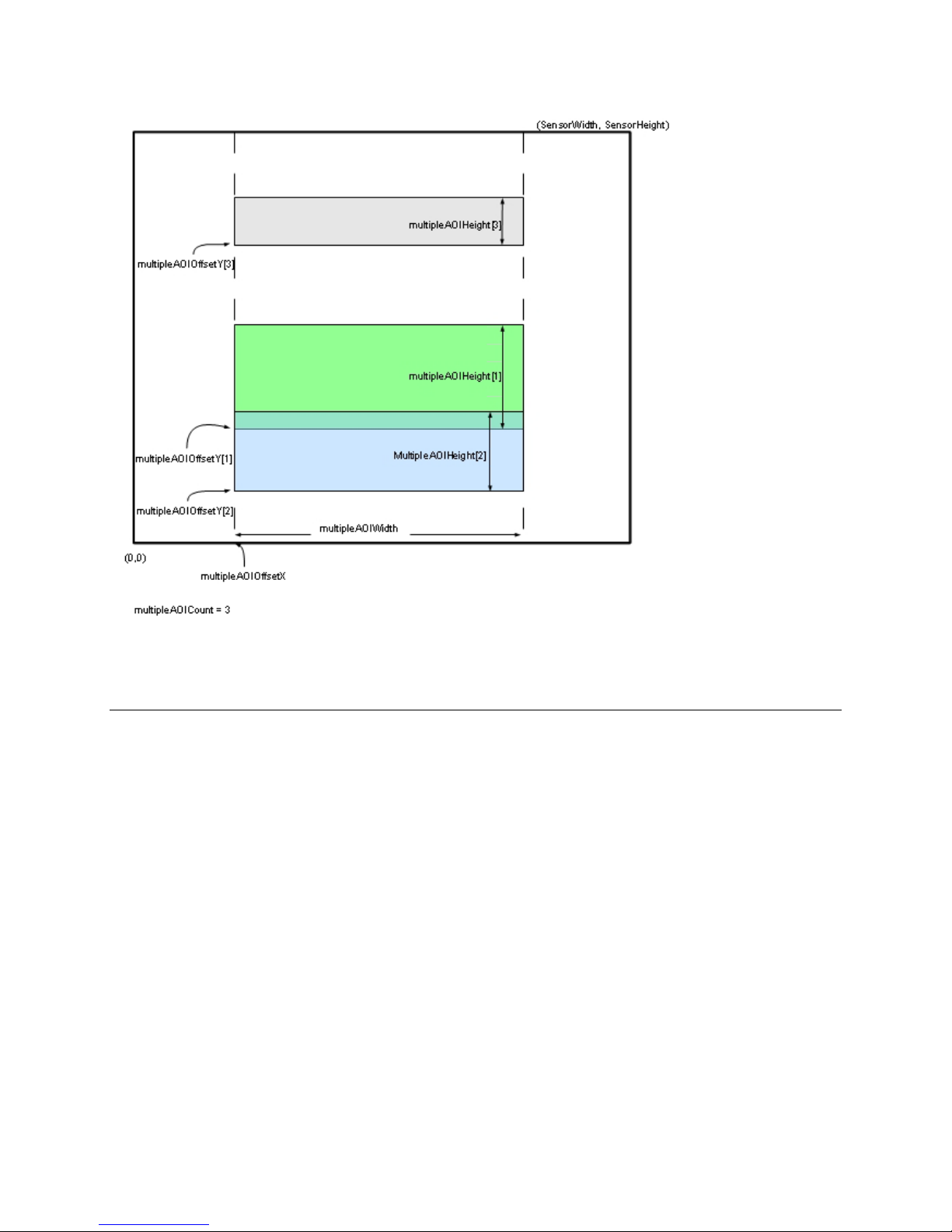
Figure 31 Multiple Areas of Interest
Note: Overlapping regions will be combined.
Camera Link Transport Layer Category
The camera’s Camera Link Transport Layer category groups parameters used to document
and configure the Camera Link output of the camera.
Parameters in gray are read only, either always or due to another parameter being disabled.
Parameters in black are user set in CamExpert or programmable via an imaging application.
Features listed in the description table but tagged as Invisible are usually for Teledyne
DALSA Support or third party software usage—and are not typically required by end user
applications.
Camera Operation • 85

Name
ClConfiguration
Name
ClTimeSlotsCount [TBC]
Figure 32 Camera Link Transport Layer as shown in CamExpert
Camera Link Transport Layer Feature Description
The following table describes the category’s parameters along with their view attribute and
minimum camera firmware version required. Additionally the table will indicate which
parameter is a member of the DALSA Features Naming Convention (DFNC), GenICam
Standard Features Naming Convention, or a custom camera feature.
Display Name CameraLink Configuration
Name Space DFNC
Firmware Release 00
Visibility Beginner
Access Read-Only
Type Enumeration
Values Full - Standard full configuration described by the Camera Link standard.</Description>.
Deca - Standard Deca configuration with 10 taps / 8-bit, as described by the Camera Link
Standard.
Notes Describes the camera's current CameraLink configuration.
Display Name CameraLink TimeSlots
Name Space DFNC
Firmware Release 00
Visibility Beginner
Access Read-Only
Type Enumeration
Values One – All camera tap data is sent in one time slot.
Notes Displays the number of consecutive time slots required for one complete data transfer of
all camera taps. For example, when sending 4 taps over a 2 tap configuration, the required
number of timeslots is 2.
86 • Camera Operation

Name
deviceTapCount
Display Name CameraLink Taps
Name
clDeviceClockFrequency
Name
clFrameValidPreTrigger
Name
clSmoothLineValidTiming
Name
DeviceTapGeometry
Name Space DFNC
Firmware Release 00
Visibility Beginner
Access Read-Write
Type Enumeration
Values Eight – The camera outputs 8 Taps
Ten – The camera outputs 10 Taps
Notes Number of physical Camera Link taps in the camera in the current configuration.
Display Name CameraLink Pixel Clock Frequency
Name Space DFNC
Firmware Release 00
Visibility Beginner
Access Read-Only
Type Integer
Units Hz
Values 76000000
Notes The frequency of the clock on the Camera Link cables.
Display Name Frame Valid PreTrigger
Name Space Custom
Firmware Release 05
Visibility Guru
Access Read-Write
Type Integer
Values 0 to 15
Notes Some third party frame grabbers require that the FVAL and the first LVAL are separated by
a given amount of time. This feature sets the number of clocks to add to the FVAL
transition before the LVAL goes high.
This feature is not necessary for Teledyne DALSA frame grabbers.
Display Name Smooth Line Valid Timing
Name Space Custom
Firmware Release 05
Visibility Guru
Access Read-Write
Type Enumeration
Values Disable - Line Valid signal is not regulated
Enable - Line Valid signal is regulated to come out of the camera at regular intervals.
Notes Some third party frame grabbers require that the LVAL signal be at regular intervals. This
Display Name Device Tap Geometry
feature regulates the sensor’s LVAL signal to produce a regular signal train.
This feature is not necessary for Teledyne DALSA frame grabbers.
Camera Operation • 87

Name Space SFNC
Name
DeviceReset
Name
streamingDeviceTapCount
Firmware Release 00
Visibility Beginner
Access Read-Write
Type Enumeration
Values Geometry_1X8_1Y - 8 tap area scan, with 1 zone in X with 8 alternating taps & 1 zone in
Notes The tap geometry describes the geometrical properties characterizing the different taps of
Display Name Device Reset
Name Space SFNC
Firmware Release 00
Visibility Beginner
Access Read-Write
Type Command
Notes Currently the camera will send a response to this command because it is resetting itself.
Y.
Tap 1 starts with pixel coordinate (1,1), extending to the image width -1 and height, using
a step of 8 (that is x = 1, 9, 17,…).
Tap 2 starts with pixel coordinate (2,1), extending to the image width and height, using a
step of 8 (that is, x = 2, 10, 18, …).
Etc.
Geometry_1X10_1Y - 10 tap area scan, with 1 zone in X with 10 alternating taps & 1 zone
in Y.
Tap 1 starts with pixel coordinate (1,1), extending to the image width -1 and height, using
a step of 10 (that is x = 1, 11, 21,…).
Tap 2 starts with pixel coordinate (2,1), extending to the image width and height, using a
step of 10 (that is, x = 2, 12, 22, …).
Etc.
a multi-tap camera.
This will result in an error in the host application.
Invisible Features
Name Space Custom
Firmware Release 05
Visibility Invisible
Access Beginner
Type Enumeration
Values Same as deviceTapCount
Notes Internal use. Used to support streaming
88 • Camera Operation

Serial Port Control Category
Name
DeviceSerialPortBaudRate
Parameters in gray are read only, either always or due to another parameter being disabled.
Parameters in black are user set in CamExpert or programmable via an imaging application.
Figure 33 Serial Port control Category in CamExpert
Feature Description
The following table describes the category’s parameters along with their view attribute and
minimum camera firmware version required. Additionally the table will indicate which
parameter is a member of the DALSA Features Naming Convention (DFNC), GenICam
Standard Features Naming Convention or a custom camera feature.
Display Name Serial Port Baud Rate
Name Space DFNC
Firmware Release 00
Visibility Beginner
Access Read-Write
Type Enumeration
Values 9600
19200
57600
115200
230400
460800
Notes The Falcon2 camera will always boot in 9600 baud.
In firmware version 4 and later, the camera automatically saves the baud rate in nonvolatile memory and will try to use that speed to communicate after the next power cycle.
See A ut o m at i c Seri al Sp eed D etect io n for information about how the serial speed is
Camera Operation • 89

determined.
Name
deviceSerialPortDataSize
Name
deviceSerialPortParity
Name
deviceSerialPortNumberOfStopBits
Display Name Serial Port Data Size
Name Space DFNC
Firmware Release 00
Visibility Beginner
Access Read-Only
Type Enumeration
Values bcp8 -8 bits per character
Notes The number of bits that transmit a single character
Display Name Serial Port Parity
Name Space DFNC
Firmware Release 00
Visibility Beginner
Access Read-Only
Type Enumeration
Values None – no partiy
Notes
Display Name Serial Port Number Of StopBits
Name Space DFNC
Firmware Release 00
Visibility Beginner
Access Read-Only
Type Enumeration
Values Stopbits1 – stop bit
Notes The number of bits used to indicate that a character has been transmitted.
Automatic Serial Speed Detection
In order for the camera and the frame grabber to communicate they both must be set to
the same baud rate (serial speed).
The serial protocol automatically detects the speed of camera by the following steps:
1. Set the serial speed of the frame grabber and send a command to the camera
2. If the camera doesn’t respond after a defined time, then repeat step 1.
3. Once communication has been established the camera will set the serial speed to the
maximum value that both the camera and frame grabber can support (firmware
versions 0 to 3).
In firmware version 4 or later, the maximum value will be the previously set value of the
DeviceSerialPortBaudRate feature.
File Access Control Category
The File Access control in CamExpert allows the user to quickly upload various data files to
the connected Falcon2. The supported data files are for Falcon2 firmware updates, Flat Field
coefficients, and files to debug the camera.
90 • Camera Operation

Name
FileSelector
Name
FileOperationSelector
Figure 34 File Access Control Category in CamExpert
Display Name File Selector
Name Space SFNC
Firmware Release 00
Visibility Beginner
Access Read-Write
Type Enumeration
Values Firmware: [Write-Only] Writing a new firmware here will update the camera.
UserFlatfieldCoefficients1: Previously saved flat field coefficients (i.e. gain and offset).
UserFlatfieldCoefficients2: Previously saved flat field coefficients (i.e. gain and offset).
UserFlatfieldCoefficients3: Previously saved flat field coefficients (i.e. gain and offset).
UserFlatfieldCoefficients4: Previously saved flat field coefficients (i.e. gain and offset).
Logs: [Read-Only] Download camera logs. This is a zipped file.
CameraSettings: [Read-Only] Download camera settings. This is a html file. Please save
with a htm extension.
TestFile: Dummy read and write file.
Notes Selects the file to access. The file types which are accessible are device dependent.
Display Name File Operation Selector
Name Space SFNC
Firmware Release 00
Visibility Beginner
Access Read-Write
Type Enumeration
Values Open: Select the Open operation - executed by FileOperationExecute.
Close: Select the Close operation - executed by FileOperationExecute.
Read: Select the Read operation - executed by FileOperationExecute.
Write: Select the Write operation - executed by FileOperationExecute
Delete: Select the Delete operation - executed by FileOperationExecute
Notes Selects the target operation for the selected file in the device. This operation is executed
when the File Operation Execute feature is called.
Camera Operation • 91

Name
FileOperationExecute
Display Name File Operation Execute
Name
FileOpenMode
Name
FileAccessBuffer
Name
FileAccessOffset
Name
FileAccessLength
Name
File Operation Status
Name Space SFNC
Firmware Release 00
Visibility Beginner
Access Read-Write
Type Command
Notes Executes the operation selected by File Operation Selector on the selected file.
Display Name File Open Mode
Name Space SFNC
Firmware Release 00
Visibility Beginner
Access Read-Write
Type Enumeration
Values Read: Select READ only open mode
Write: Select WRITE only open mode
Notes Selects the access mode used to open a file on the device.
Display Name File Access Buffer
Name Space SFNC
Firmware Release 00
Visibility Beginner
Access Read-Write
Type Enumeration
Notes Defines the intermediate access buffer that allows the exchange of data between the
device file storage and the application.
Display Name File Access Offset
Name Space SFNC
Firmware Release 00
Visibility Beginner
Access Read-Write
Type Enumeration
Values 0 to (FileSize-1) or 16777216, whichever value is smaller.
Notes Controls the mapping offset between the device file storage and the file access buffer.
Display Name File Access Length
Name Space SFNC
Firmware Release 00
Visibility Beginner
Access Read-Write
Type Enumeration
Values 1 to Maximum size of FileAccessBuffer
Notes Controls the mapping length between the device file storage and the file access buffer.
Display Name File Operation Status
92 • Camera Operation

Name Space SFNC
Name
FileOperationResult
Name
FileSize
Firmware Release 00
Visibility Beginner
Access Read-Only
Type Enumeration
Values Success: The last file operation has completed successfully.
Failure:The last file operation has completed unsuccessfully for an unknown reason.
FileUnavailable:The last file operation has completed unsuccessfully because the file is
currently unavailable.
FileInvalid: The last file operation has completed unsuccessfully because the selected file in
not present in this camera model.
Notes Selects the access mode used to open a file on the device.
Display Name File Operation Result
Name Space SFNC
Firmware Release 00
Visibility Beginner
Access Read-Only
Type Enumeration
Notes Displays the file operation result. For Read or Write operations, the number of successfully
Display Name File Size
Name Space SFNC
Firmware Release 00
Visibility Beginner
Access Read-Write
Type Enumeration
Notes Represents the size of the selected file in bytes.
read/written bytes is returned.
Camera Operation • 93
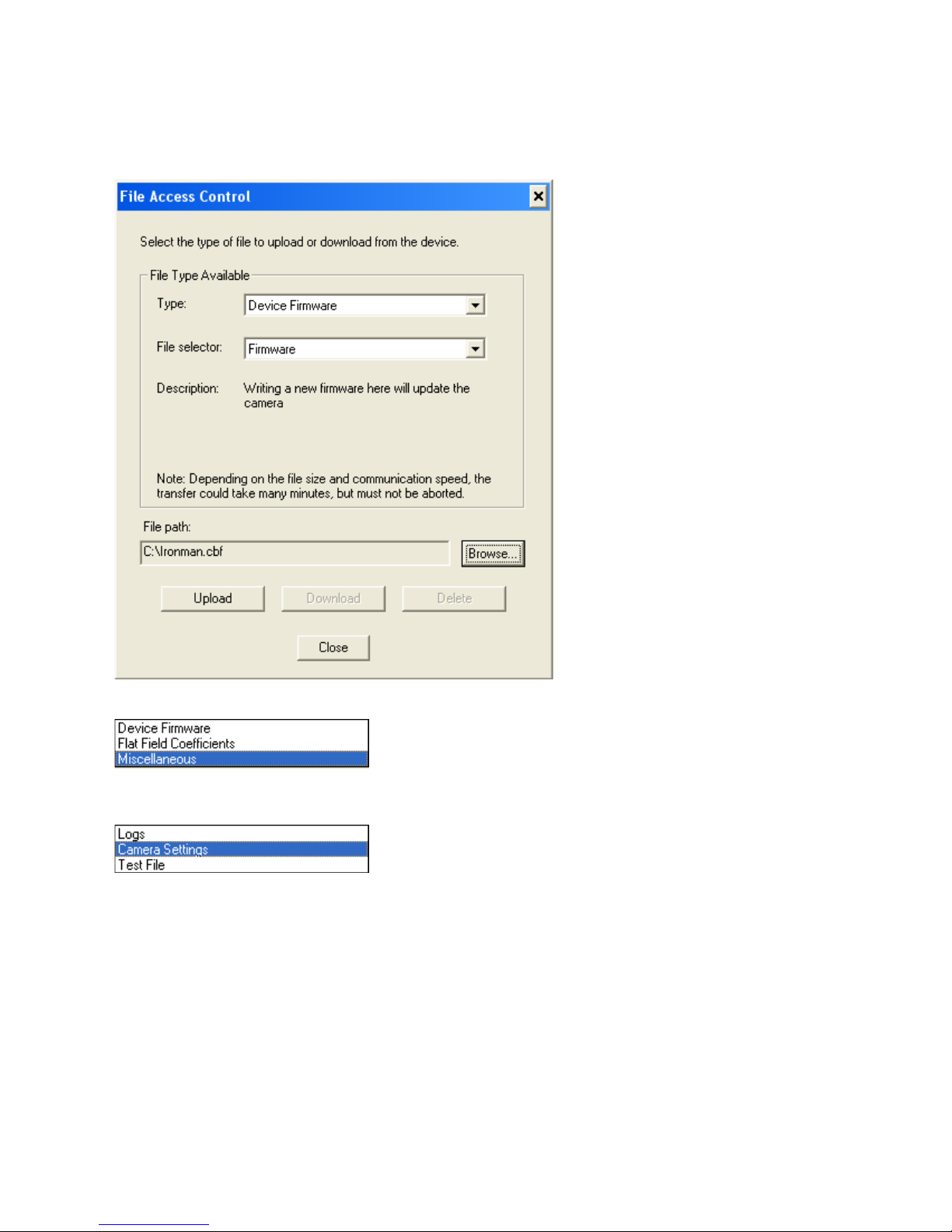
File Access via the CamExpert Tool
1. Click on the “Setting…” button to show the file selection menu.
Figure 35 Initial File Access Control Dialog
2. From the Type drop menu, select the file type that will be uploaded to the camera.
3. From the File Selector drop menu, select the camera memory location for the
uploaded data. This menu presents only the applicable data locations for the selected
file type.
4. Click the Browse button to open a typical Windows Explorer window.
5. Select the specific file from the system drive or from a network location.
6. Click the Download button to execute the file transfer from the Falcon2.
7. Note that firmware changes require a device reset command.
94 • Camera Operation

Appendix A: Camera Link
Clocking Signal
Indicates
Output Signals, Camera Link Clocking Signals
These signals indicate when data is valid, allowing you to clock the data from the camera to
your acquisition system. These signals are part of the Camera Link configuration and you
should refer to the Camera Link Implementation Road Map, available at our
Center, for the standard location of these signals.
LVAL (high) Outputting valid line
DVAL Not used, stuck low
STROBE (rising edge) Valid data
FVAL (high) Outputting valid frame
The sensor internally digitizes to 10, 9, or 8 bits. The camera outputs the 8 most significant
bits (MSB’s) or all 10-bits depending on the Camera Link mode that the camera is
operating in.
Camera Link cable quality and length
The maximum allowable Camera Link cable length depends on the quality of the cable used
and the Camera Link strobe frequency. Cable quality degrades over time as the cable is
flexed. In addition, as the Camera Link strobe frequency is increased the maximum
allowable cable length will decrease.
The cameras are capable of driving cables less than 7 metres in length. We do not
guarantee good imaging performance with low quality cables of any length. In general, we
recommend the use of high quality cables for any cable length.
Knowledge
Recommended Cables
We recommend the use of high-quality mini-CL cables. Teledyne DALSA has 3 meter and 5
meter cables available as accessories. Contact Customer Support.
Data Connector: Camera Link
The camera uses two mini-Camera Link SDR-26 cables transmitting the Camera Link Full or
Extended configuration. The figure below shows the SDR-26 mini Camera Link Connector
and the tables that follow list the Camera Link Full and Extended configurations.
For detailed information on Camera Link please refer to the Camera Link Road Map available
from the Knowledge Center on the Teledyne DALSA Web site:
(http://www.teledynedalsa.com/mv/knowledge/appnotes.aspx
• 95
).

Figure 36: SDR-26 Mini Camera Link Connector
Data 2
Control / Data 1
Connector
Connector
Camera
Connector
1 1 inner shield 1 1 inner shield
14 14 inner shield 14 14 inner shield
2 25 Y0- 2 25 X0-
15 12 Y0+ 15 12 X0+
3 24 Y1- 3 24 X1-
16 11 Y1+ 16 11 X1+
4 23 Y2- 4 23 X2-
17 10 Y2+ 17 10 X2+
5 22 Yclk- 5 22 Xclk-
18 9 Yclk+ 18 9 Xclk+
6 21 Y3- 6 21 X3-
19 8 Y3+ 19 8 X3+
7 20 100 ohm 7 20 SerTC+
20 7 terminated 20 7 SerTC-
8 19 Z0- 8 19 SerTFG-
21 6 Z0+ 21 6 SerTFG+
9 18 Z1- 9 18 CC1-
22 5 Z1+ 22 5 CC1+
10 17 Z2- 10 17 CC2+
23 4 Z2+ 23 4 CC2-
11 16 Zclk- 11 16 CC3-
24 3 Zclk+ 24 3 CC3+
12 15 Z3- 12 15 CC4+
25 2 Z3+ 25 2 CC4-
13 13 inner shield 13 13 inner shield
26 26 inner shield 26 26 inner shield
Right Angle
Frame Grabber
Channel Link
Signal
Camera
Connector
Right Angle
Frame Grabber
Channel Link
Signal
*Exterior Overshield is connected to the shells of the connectors on both ends. Unused pairs
should be terminated in 100 ohms at both ends of the cable. Inner shield is connected to
signal ground inside camera
96 • Appendix A: Camera Link

Full Configuration
Connector 1: Channel link X
Connector 2: Channel link Y
Connector 3: Channel link Z
Grabber Pin
Bit Name
Grabber Pin
Bit Name
Grabber Pin
Bit Name
Tap 1 bits are D0(x)…Tap 8 bits are D7(x)
8 taps 8 bits Camera link Full configuration
Camera/Frame
Tx0/Rx0 D0(0) Tx0/Rx0 D3(0) Tx0/Rx0 D6(0)
Tx1/Rx1 D0(1) Tx1/Rx1 D3(1) Tx1/Rx1 D6(1)
Tx2/Rx2 D0(2) Tx2/Rx2 D3(2) Tx2/Rx2 D6(2)
Tx3/Rx3 D0(3) Tx3/Rx3 D3(3) Tx3/Rx3 D6(3)
Tx4/Rx4 D0(4) Tx4/Rx4 D3(4) Tx4/Rx4 D6(4)
Tx5/Rx5 D0(7) Tx5/Rx5 D3(7) Tx5/Rx5 D6(7)
Tx6/Rx6 D0(5) Tx6/Rx6 D3(5) Tx6/Rx6 D6(5)
Tx7/Rx7 D1(0) Tx7/Rx7 D4(0) Tx7/Rx7 D7(0)
Tx8/Rx8 D1(1) Tx8/Rx8 D4(1) Tx8/Rx8 D7(1)
Tx9/Rx9 D1(2) Tx9/Rx9 D4(2) Tx9/Rx9 D7(2)
Tx10/Rx10 D1(6) Tx10/Rx10 D4(6) Tx10/Rx10 D7(6)
Tx11/Rx11 D1(7) Tx11/Rx11 D4(7) Tx11/Rx11 D7(7)
Tx12/Rx12 D1(3) Tx12/Rx12 D4(3) Tx12/Rx12 D7(3)
Tx13/Rx13 D1(4) Tx13/Rx13 D4(4) Tx13/Rx13 D7(4)
Tx14/Rx14 D1(5) Tx14/Rx14 D4(5) Tx14/Rx14 D7(5)
Tx15/Rx15 D2(0) Tx15/Rx15 D5(0) Tx15/Rx15 Not Used
Tx16/Rx16 D2(6) Tx16/Rx16 D5(6) Tx16/Rx16 Not Used
Tx17/Rx17 D2(7) Tx17/Rx17 D5(7) Tx17/Rx17 Not Used
Tx18/Rx18 D2(1) Tx18/Rx18 D5(1) Tx18/Rx18 Not Used
Tx19/Rx19 D2(2) Tx19/Rx19 D5(2) Tx19/Rx19 Not Used
Tx20/Rx20 D2(3) Tx20/Rx20 D5(3) Tx20/Rx20 Not Used
Tx21/Rx21 D2(4) Tx21/Rx21 D5(4) Tx21/Rx21 Not Used
Tx22/Rx22 D2(5) Tx22/Rx22 D5(5) Tx22/Rx22 Not Used
Tx23/Rx23 Not Used Tx23/Rx23 Not Used Tx23/Rx23 Not Used
Tx24/Rx24 LVAL Tx24/Rx24 LVAL Tx24/Rx24 LVAL
Tx25/Rx25 FVAL Tx25/Rx25 FVAL Tx25/Rx25 FVAL
Tx26/Rx26 Not Used Tx26/Rx26 Not Used Tx26/Rx26 Not Used
Tx27/Rx27 D0(6) Tx27/Rx27 D3(6) Tx27/Rx27 D6(6)
Camera/Frame
Camera/Frame
Appendix A: Camera Link • 97

Extended Configurations
Connector 1: Channel link X
Connector 1: Channel link Y
Connector 1: Channel link Z
Grabber Pin
Bit Name
Grabber Pin
Bit Name
Grabber Pin
Bit Name
10 taps 8 bits Camera link Extended configuration
Camera/Frame
Tx0/Rx0 D0(0) Tx0/Rx0 D3(2) Tx0/Rx0 D6(5)
Tx1/Rx1 D0(1) Tx1/Rx1 D3(3) Tx1/Rx1 D6(6)
Tx2/Rx2 D0(2) Tx2/Rx2 D3(4) Tx2/Rx2 D6(7)
Tx3/Rx3 D0(3) Tx3/Rx3 D3(5) Tx3/Rx3 D7(0)
Tx4/Rx4 D0(4) Tx4/Rx4 D3(6) Tx4/Rx4 D7(1)
Tx5/Rx5 D0(5) Tx5/Rx5 D3(7) Tx5/Rx5 D7(2)
Tx6/Rx6 D0(6) Tx6/Rx6 D4(0) Tx6/Rx6 D7(3)
Tx7/Rx7 D0(7) Tx7/Rx7 D4(1) Tx7/Rx7 D7(4)
Tx8/Rx8 D1(0) Tx8/Rx8 D4(2) Tx8/Rx8 D7(5)
Tx9/Rx9 D1(1) Tx9/Rx9 D4(3) Tx9/Rx9 D7(6)
Tx10/Rx10 D1(2) Tx10/Rx10 D4(4) Tx10/Rx10 D7(7)
Tx11/Rx11 D1(3) Tx11/Rx11 D4(5) Tx11/Rx11 D8(0)
Tx12/Rx12 D1(4) Tx12/Rx12 D4(6) Tx12/Rx12 D8(1)
Tx13/Rx13 D1(5) Tx13/Rx13 D4(7) Tx13/Rx13 D8(2)
Tx14/Rx14 D1(6) Tx14/Rx14 D5(0) Tx14/Rx14 D8(3)
Tx15/Rx15 D1(7) Tx15/Rx15 D5(1) Tx15/Rx15 D8(4)
Tx16/Rx16 D2(0) Tx16/Rx16 D5(2) Tx16/Rx16 D8(5)
Tx17/Rx17 D2(1) Tx17/Rx17 D5(3) Tx17/Rx17 D8(6)
Tx18/Rx18 D2(2) Tx18/Rx18 D5(4) Tx18/Rx18 D8(7)
Tx19/Rx19 D2(3) Tx19/Rx19 D5(5) Tx19/Rx19 D9(0)
Tx20/Rx20 D2(4) Tx20/Rx20 D5(6) Tx20/Rx20 D9(1)
Tx21/Rx21 D2(5) Tx21/Rx21 D5(7) Tx21/Rx21 D9(2)
Tx22/Rx22 D2(6) Tx22/Rx22 D6(0) Tx22/Rx22 D9(3)
Tx23/Rx23 D2(7) Tx23/Rx23 D6(1) Tx23/Rx23 D9(4)
Tx24/Rx24 LVAL Tx24/Rx24 D6(2) Tx24/Rx24 D9(5)
Tx25/Rx25 FVAL Tx25/Rx25 D6(3) Tx25/Rx25 D9(6)
Tx26/Rx26 D3(0) Tx26/Rx26 D6(4) Tx26/Rx26 D9(7)
Tx27/Rx27 D3(1) Tx27/Rx27 LVAL Tx27/Rx27 LVAL
Camera/Frame
Camera/Frame
98 • Appendix A: Camera Link

Connector 1: Channel link X
Connector 1: Channel link Y
Connector 1: Channel link Z
Grabber Pin
Bit Name
Grabber Pin
Bit Name
Grabber Pin
Bit Name
8 taps 10 bits Camera link Extended configuration
Camera/Frame
Tx0/Rx0 D0(2) Tx0/Rx0 D3(2) Tx0/Rx0 D6(2)
Tx1/Rx1 D0(3) Tx1/Rx1 D3(3) Tx1/Rx1 D6(3)
Tx2/Rx2 D0(4) Tx2/Rx2 D3(4) Tx2/Rx2 D6(4)
Tx3/Rx3 D0(5) Tx3/Rx3 D3(5) Tx3/Rx3 D6(5)
Tx4/Rx4 D0(6) Tx4/Rx4 D3(6) Tx4/Rx4 D6(6)
Tx5/Rx5 D0(9) Tx5/Rx5 D3(9) Tx5/Rx5 D6(9)
Tx6/Rx6 D0(7) Tx6/Rx6 D3(7) Tx6/Rx6 D6(7)
Tx7/Rx7 D1(2) Tx7/Rx7 D4(2) Tx7/Rx7 D7(2)
Tx8/Rx8 D1(3) Tx8/Rx8 D4(3) Tx8/Rx8 D7(3)
Tx9/Rx9 D1(4) Tx9/Rx9 D4(4) Tx9/Rx9 D7(4)
Tx10/Rx10 D1(8) Tx10/Rx10 D4(8) Tx10/Rx10 D7(8)
Tx11/Rx11 D1(9) Tx11/Rx11 D4(9) Tx11/Rx11 D7(9)
Tx12/Rx12 D1(5) Tx12/Rx12 D4(5) Tx12/Rx12 D7(5)
Tx13/Rx13 D1(6) Tx13/Rx13 D4(6) Tx13/Rx13 D7(6)
Tx14/Rx14 D1(7) Tx14/Rx14 D4(7) Tx14/Rx14 D7(7)
Tx15/Rx15 D2(2) Tx15/Rx15 D5(2) Tx15/Rx15 D2(1)
Tx16/Rx16 D2(8) Tx16/Rx16 D5(8) Tx16/Rx16 D5(1)
Tx17/Rx17 D2(9) Tx17/Rx17 D5(9) Tx17/Rx17 D6(0)
Tx18/Rx18 D2(3) Tx18/Rx18 D5(3) Tx18/Rx18 D3(0)
Tx19/Rx19 D2(4) Tx19/Rx19 D5(4) Tx19/Rx19 D3(1)
Tx20/Rx20 D2(5) Tx20/Rx20 D5(5) Tx20/Rx20 D4(0)
Tx21/Rx21 D2(6) Tx21/Rx21 D5(6) Tx21/Rx21 D4(1)
Tx22/Rx22 D2(7) Tx22/Rx22 D5(7) Tx22/Rx22 D5(0)
Tx23/Rx23 D0(1) Tx23/Rx23 D2(0) Tx23/Rx23 D7(1)
Tx24/Rx24 LVAL Tx24/Rx24 LVAL Tx24/Rx24 LVAL
Tx25/Rx25 FVAL Tx25/Rx25 D1(0) Tx25/Rx25 D6(1)
Tx26/Rx26 D0(0) Tx26/Rx26 D1(1) Tx26/Rx26 D7(0)
Tx27/Rx27 D0(8) Tx27/Rx27 D3(8) Tx27/Rx27 D6(8)
Camera/Frame
Camera/Frame
Appendix A: Camera Link • 99

Appendix B: Camera, Frame
Grabber Communication
Setting Up Communication between the Camera and the Frame
Grabber
Teledyne DALSA Camera Link cameras support the GenCP CameraLink standards.
To configure Teledyne DALSA GenCP Camera Link Cameras:
1. Install the Teledyne DALSA frame grabber in the host computer; refer to the
hardware installation manual
2. Install Sapera LT and the Teledyne DALSA frame grabber driver.
3. Connect the camera to the frame grabber; refer to the camera installation manual.
4. Run the Sapera Configuration utility, select the frame grabber serial port connected
to the camera, and set the Enable camera detection parameter to Yes.
5. Start the CamExpert application. In the Device tab, select either the camera or frame
grabber to adjust their parameters; currently, for GenCP cameras, the camera and
100 • Appendix B: Camera, Frame Grabber Communication
 Loading...