


Configuration and Data
Hybrid audio and video recorder
English
DMS 80
DMS 160
DMS 240
DMS 240 HSR
Rev. 5.0.1 / 2010-06-22

DMS 80 / DMS 160 / DMS 240 / DMS 240 HSR
Information about copyright, trademarks, design patents
© 2010 Dallmeier electronic
The reproduction, distribution and utilization of this document as well as the communication of
its contents to others without express authorization is prohibited. Offenders will be held liable for
the payment of damages. All rights reserved in the event of the grant of a patent, utility model or
design.
We reserve the right to make technical modications.
The manufacturer accepts no liability for damage to property or pecuniary damages arising due
to minor defects of the product or documentation, e.g. print or spelling errors, and for those not
caused by intention or gross negligence of the manufacturer.
Dallmeier electronic GmbH & Co.KG
Cranachweg 1
93051 Regensburg, Germany
www.dallmeier.com
info@dallmeier.com
All trademarks identied by ® are registered trademarks of Dallmeier electronic.
All trademarks identied by *) are trademarks or registered trademarks of the following owners:
Adobe and Flash of Adobe Systems Incorporated headquartered in San José, California, USA
Sony, EXview HAD and Super HAD of Sony Corporation headquartered in Tokyo, Japan
Third-party trademarks are named for information purposes only.
Dallmeier electronic respects the intellectual property of third parties and always attempts to ensure the complete identication of third-party
trademarks and indication of the respective holder of rights. In case that protected rights are not indicated separately, this circumstance is
no reason to assume that the respective trademark is unprotected.
www.dallmeier.com 2

DMS 80 / DMS 160 / DMS 240 / DMS 240 HSR
Table of contens
1 This document ..............................................................................................8
1.1 Validity .............................................................................................................8
1.2 Documents ......................................................................................................8
1.2 Conventions ....................................................................................................8
2 Safety instructions......................................................................................10
3 General instructions ...................................................................................12
3.1 Scope of delivery ..........................................................................................12
3.2 Transportation and packaging ......................................................................12
3.3 Warranty ......................................................................................................12
4 Start and Login............................................................................................13
5 Basic settings..............................................................................................15
5.1 Language ......................................................................................................15
5.2 System time ..................................................................................................15
5.2.1 Setting ...........................................................................................................16
5.2.2 Time server ...................................................................................................16
5.2.3 Radio clock ...................................................................................................16
5.3 System security.............................................................................................17
5.4 Options..........................................................................................................17
5.4.1 Alarm duration...............................................................................................18
5.4.2 Test modes....................................................................................................18
5.4.2.1 Compare .......................................................................................................19
5.4.2.2 Performance .................................................................................................20
5.4.2.3 Tracking ........................................................................................................20
5.4.3 Keyboard mode.............................................................................................21
5.4.4 Single split replay ..........................................................................................21
5.4.5 Playback monitor ..........................................................................................22
5.4.6 System messages.........................................................................................23
5.4.7 Assistant mode .............................................................................................24
5.4.8 Recording timeout .........................................................................................24
5.4.8.1 Max. recording pause ...................................................................................25
5.4.8.2 Min. Storage period.......................................................................................25
5.4.9 OSD texts......................................................................................................26
5.4.10 Logging .........................................................................................................28
5.4.11 Recording monitor.........................................................................................29
5.4.12 Simple Export................................................................................................29
5.4.13 Audio deactivation.........................................................................................30
6 Recording setting .......................................................................................31
6.1 Track mode ...................................................................................................31
6.1.1 Standard .......................................................................................................32
6.1.1.1 Recording......................................................................................................32
6.1.1.2 Modications .................................................................................................32
6.1.1.3 Track types ...................................................................................................32
6.1.1.4 Recording modes ..........................................................................................33
6.1.2 Manual ..........................................................................................................33
6.1.2.1 Recording......................................................................................................33
www.dallmeier.com 3

DMS 80 / DMS 160 / DMS 240 / DMS 240 HSR
6.1.2.2 Modications .................................................................................................34
6.1.2.3 Track types ...................................................................................................34
6.1.2.4 Recording modes ..........................................................................................34
6.1.3 Automatic ......................................................................................................34
6.1.3.1 Recording......................................................................................................35
6.1.3.2 Modications .................................................................................................35
6.1.3.3 Track types ...................................................................................................35
6.1.3.4 Recording modes ..........................................................................................35
6.1.4 Change .........................................................................................................36
6.2 Connection ....................................................................................................37
6.2.1 Analogue cameras ........................................................................................37
6.2.2 IP cameras ....................................................................................................37
6.2.2.1 Dallmeier IP and HD cameras ......................................................................37
6.2.2.2 Other IP cameras ..........................................................................................38
6.3 Basic conguration........................................................................................39
6.3.1 Camera and track name ...............................................................................39
6.3.2 Camera timer ................................................................................................40
6.3.3 Tracks timer ..................................................................................................42
6.3.4 Areas.............................................................................................................42
6.3.4.1 Active areas ..................................................................................................42
6.3.4.2 Private Zones ................................................................................................43
6.4 Recording mode............................................................................................45
6.4.1 Manual and automatic mode.........................................................................45
6.4.1.1 Permanent ....................................................................................................46
6.4.1.2 Motion ...........................................................................................................47
6.4.1.3 Contact..........................................................................................................48
6.4.1.4 Switching by motion ......................................................................................49
6.4.1.5 Switching by contact .....................................................................................50
6.4.1.6 Switching by timer .........................................................................................50
6.4.2 Standard mode .............................................................................................52
6.4.2.1 Permanent ....................................................................................................52
6.4.2.2 Motion ...........................................................................................................53
6.4.2.3 Contact..........................................................................................................54
6.4.2.4 Sensor...........................................................................................................56
6.5 Video quality .................................................................................................56
6.5.1 Manual and automatic mode.........................................................................56
6.5.1.1 Analogue cameras ........................................................................................56
6.5.1.2 Dallmeier IP and HD cameras ......................................................................57
6.5.1.3 Other IP cameras ..........................................................................................59
6.5.2 Standard mode .............................................................................................60
6.5.2.1 Analogue cameras ........................................................................................60
6.5.2.2 Dallmeier IP and HD cameras ......................................................................60
6.5.2.3 Other IP cameras ..........................................................................................61
6.5.3 Optional conguration ...................................................................................62
6.5.3.1 Direct conguration .......................................................................................62
6.5.3.2 Auto conguration .........................................................................................62
6.5.3.3 B-Frames ......................................................................................................63
6.6 Activation ......................................................................................................63
6.7 Video memory ...............................................................................................64
6.7.1 Standard .......................................................................................................64
www.dallmeier.com 4

DMS 80 / DMS 160 / DMS 240 / DMS 240 HSR
6.7.1.1 Longplay tracks .............................................................................................64
6.7.1.2 Secure tracks ................................................................................................65
6.7.1.3 Fixed recording duration ...............................................................................66
6.7.2 Manual ..........................................................................................................66
6.7.3 Automatic ......................................................................................................67
6.8 Other functions..............................................................................................67
6.8.1 Audio .............................................................................................................67
6.8.2 Dual Streaming .............................................................................................67
6.8.3 SEDOR .........................................................................................................68
6.8.4 SmartFinder ..................................................................................................71
6.8.5 Camera control .............................................................................................72
7 Display settings ..........................................................................................74
7.1 Splitter ...........................................................................................................75
7.1.1 Automatic assignment...................................................................................76
7.1.2 Manual assignment .......................................................................................76
7.2 Sequencer.....................................................................................................77
7.2.1 VGA display sequence ..................................................................................77
7.2.2 CVBS display sequence ...............................................................................79
7.2.3 Display frame rate .........................................................................................79
7.2.4 OSD display ..................................................................................................80
8 Network and PAS ........................................................................................81
8.1 Ethernet ........................................................................................................81
8.1.1 Manual conguration.....................................................................................82
8.1.2 DHCP ............................................................................................................82
8.2 PSTN/Terminal-Adapter ................................................................................83
8.3 Alarm hosts ...................................................................................................83
8.3.1 Selection and name ......................................................................................83
8.3.2 Connection ....................................................................................................84
8.3.3 Alternative alarm host ...................................................................................85
8.3.4 Connection check .........................................................................................86
8.3.5 Messages......................................................................................................87
8.3.6 Timer .............................................................................................................90
8.3.7 Activation ......................................................................................................91
8.3.8 EBueS ...........................................................................................................91
8.4 Parameter backup.........................................................................................92
8.4.1 Export............................................................................................................92
8.4.2 Import ............................................................................................................93
9 Serial Interface ............................................................................................94
9.1 Setting ...........................................................................................................94
9.2 Functions ......................................................................................................94
10 Contact IN ....................................................................................................96
10.1 Global and camera-related contacts .............................................................96
10.2 Make and break contact functions ................................................................96
10.3 Setting ...........................................................................................................97
10.4 Functions ......................................................................................................98
10.5 Conguration of camera-related contacts ...................................................100
www.dallmeier.com 5

DMS 80 / DMS 160 / DMS 240 / DMS 240 HSR
11 Relay OUT ..................................................................................................101
11.1 Setting .........................................................................................................101
11.2 Functions ....................................................................................................101
12 Optional periphery ....................................................................................105
12.1 Printers........................................................................................................105
12.1.1 Create printer ..............................................................................................105
12.1.2 Set printer ...................................................................................................107
12.2 DIS control ..................................................................................................107
12.3 Storage .......................................................................................................108
12.4 Weather server ...........................................................................................108
12.5 DNI ..............................................................................................................109
12.5.1 DNI - external system .................................................................................109
12.5.2 DNI - camera control ...................................................................................110
12.6 UPS.............................................................................................................112
12.7 Card reader .................................................................................................113
12.8 VSC.............................................................................................................113
12.9 Serial PTZ cameras ....................................................................................114
12.10 UTC camera................................................................................................116
12.10.1 Required settings ........................................................................................ 116
12.10.2 Conrol panel................................................................................................118
12.10.3 Zoom function .............................................................................................118
12.10.3.1 Save zoom factor and position....................................................................119
12.10.3.2 Enter name for position ...............................................................................119
12.10.4 Congure camera .......................................................................................119
12.10.4.1 Functions ....................................................................................................121
12.10.4.2 Close menu and save conguration............................................................122
12.10.4.3 Save camera conguration for direct selection ...........................................122
12.10.5 Reset camera settings ................................................................................123
12.10.6 End UTC camera conguration...................................................................123
13 Optional functions ....................................................................................124
13.1 Signal loop through .....................................................................................124
13.2 PRemote .....................................................................................................124
14 HDD management .....................................................................................126
15 User management .....................................................................................128
15.1 Edit groups ..................................................................................................128
15.1.1 Issuing permissions ....................................................................................129
15.1.2 Change group name or login ......................................................................129
15.1.3 Dene or change passwords ......................................................................130
15.1.4 Dual-control login ........................................................................................130
15.1.5 Access restriction ........................................................................................131
15.2 Login as User ..............................................................................................131
15.2.1 Create users ...............................................................................................132
15.2.2 User rights...................................................................................................132
15.2.3 Change user password ...............................................................................133
15.2.4 Delete users ................................................................................................133
15.2.5 User options ................................................................................................134
www.dallmeier.com 6

DMS 80 / DMS 160 / DMS 240 / DMS 240 HSR
16 Service .......................................................................................................136
16.1 Activation ....................................................................................................136
16.2 Update ........................................................................................................136
17 System parameter .....................................................................................138
17.1 Default system parameters .........................................................................138
17.2 Parameter export ........................................................................................138
17.3 Parameter import ........................................................................................139
18 HDD replacement ......................................................................................140
18.1 Conditions ...................................................................................................140
18.2 Localization of the HDD ..............................................................................141
18.3 Replace the HDD ........................................................................................141
19 Technical data ...........................................................................................144
www.dallmeier.com 7

1 This document
1.1 Validity
This document applies to the hybrid audio and video recorder DMS 80 / 160 / 240 / 240 HSR.
It has been produced on the basis of version 7.0.0 (software).
The descriptions in this document apply to all above-mentioned models. For simplication
reasons, the term “DMS” is thus used. If text passages require distinctions to be made between the devices, the complete device name will be mentioned.
1.2 Documents
Commissioning
The document entitled Commissioning contains the most important steps for the connection and commissioning of the device.
Main Functions
The document entitled Main Functions contains descriptions on how to operate the essential functions of the device. The target audience of this document is the operator. No
special technical knowledge is required.
DMS 80 / DMS 160 / DMS 240 / DMS 240 HSR
Operation
The document entitled Operation contains detailed descriptions on how to operate the
unit. General information on the appropriate use and maintenance is also provided.
The target audience of this document is the operator of the unit. No special technical knowledge is required.
Conguration and data (this document)
The document entitled Conguration contains detailed descriptions conguration of the
unit. Safety notes, general information and technical data are additionally provided.
The target audience of this document is exclusively specially trained and authorized professionals (“installers”).
1.2 Conventions
This document contains various warning words and symbols that indicate potential sources
of danger.
DANGER
DANGER indicates a hazardous situation which, if not avoided, will result
in death or serious injury.
WARNING
WARNING indicates a hazardous situation which, if not avoided, could
result in death or serious injury.
www.dallmeier.com 8

DMS 80 / DMS 160 / DMS 240 / DMS 240 HSR
CAUTION
CAUTION indicates a hazardous situation which, if not avoided, could
result in minor or moderate injury.
NOTICE
NOTICE indicates practices for preventing property damage, incorrect congurations or faulty operations.
Expressions in bold/italics generally indicate a control element on the device (switches or
labels) or on its user interface (buttons, menu entries).
Paragraphs in italics provide information on basic principles, special features and efcient
procedure as well as general recommendations.
www.dallmeier.com 9

2 Safety instructions
Only use this unit if it is technically in proper working order, to the intended purpose and
while keeping safety and potential dangers in mind.
Qualied personnel
Installation, mounting, connection, commissioning and conguration of the unit may only
be carried out by qualied personnel. This also applies to the maintenance, testing and repair, whereat the regulations of the DIN VDE 0701 series of standards (repair, modication
and inspection of electrical appliances) must be followed.
Regulations
The use of video and audio surveillance systems in general is strictly regulated. Inform
yourself about the applicable laws and regulations regarding data, working and environmental protection before using the unit and ensure compliance with them.
System components
Only use internal components that have been tested and approved by Dallmeier. Inappropriate internal components can cause malfunctions, damages and data loss and can result
in loss of warranty.
DMS 80 / DMS 160 / DMS 240 / DMS 240 HSR
Modications
Do not make any modications to the hardware or software that has not been tested and
approved by Dallmeier. Inappropriate modications can cause malfunctions, damages and
data loss and can result in loss of warranty.
Documentation
Carefully and completely read the documents included in delivery. Always observe the
contained instructions, notes and warnings.
Condensation water
If the unit is brought from a cold to a warm environment, resulting condensation water
can cause malfunctions and damages. In this case wait (up to 8 hours) until the unit has
reached room temperature before commissioning.
Operating conditions
Unfavourable operating conditions can shorten the life of the unit and can cause malfunctions, damages and data los s and can result in loss of warranty. Observe the specications
given in the technical data, the operating condition requirements and the maintenance
instructions.
Shocks
Shocks can cause malfunctions and damages. The unit may not be moved while in operation.
Foreign bodies
If objects or liquids get into the unit, immediately disconnect it from the power supply (pull
out the power plug). Contact the sales partner responsible for your area.
www.dallmeier.com 10

DMS 80 / DMS 160 / DMS 240 / DMS 240 HSR
Burnt smell
If you notice burnt smell or formation of smoke from the unit, immediately disconnect it from
the power supply (pull out the power plug). Contact the sales partner responsible for your
area.
Opening
The housing of the unit may only be opened by qualied personnel for inspection, maintenance and repair.
Disposal
Disconnect the unit from the power supply. Remove all connected devices. Return the unit
to your respective sales partner.
www.dallmeier.com 11

3 General instructions
3.1 Scope of delivery
Included in the standard scope of delivery is:
1x Recorder including HDDs (as ordered)
1x Dallmeier mouse (optical, small version)
1x Power cable
1x Audio IN cable set (as ordered)
2x 9-pin D-SUB interfaces with housing
5x 8-pin Weidmüller plug connector
1x 10-pin Weidmüller plug connector
1x Spare set of lters (5 lters)
1x DVD +R1x
1x Dokumentation Conguration and Data (CD)
1x Documentation Operation (CD)
1x Documentation Commissioning (printed)
1x Documentation Main Functions (printed)
DMS 80 / DMS 160 / DMS 240 / DMS 240 HSR
The scope of delivery may differ depending on the ordered equipment or device variant.
The device’s range of functions depends on the ordered equipment or device variant and
may therefore not correspond with this document’s content. Certain functions and features
may require an activation that is subject to costs.
3.2 Transportation and packaging
Store the original packaging for transportation at a later date. Dallmeier electronic is not
responsible for damage resulting from unprofessional/improper transportation. The goods
should only be shipped in their original packaging.
If the original packaging is no longer available, ensure that the packaging used sufciently
protects the unit against damage, moisture, heat and cold.
3.3 Warranty
The terms and conditions valid at the signing of the contract shall apply.
www.dallmeier.com 12

4 Start and Login
Observe the documentation Commissioning. It contains detailed instructions on mounting, connection assignment and commissioning of the device.
¾ Connect the recorder and relevant peripherals to the voltage supply.
¾ Ensure that the VGA monitor and a mouse are connected to the recorder.
¾ Switch on the VGA monitor, the peripherals and the recorder.
The connected analogue cameras 1 - 4 are displayed after the start.
DMS 80 / DMS 160 / DMS 240 / DMS 240 HSR
Fig. 4-1
In the initial state it is possible to login without password. The rights of the Administrator group are valid.
Note that the denition of the passwords and of the network parameters is necessary
for remote access (Dallmeier PView or DMS WebCong).
¾ Left-click the background.
The Recorder login dialogue is displayed.
Fig. 4-2
¾ Click Later to login without changing a password.
www.dallmeier.com 13

DMS 80 / DMS 160 / DMS 240 / DMS 240 HSR
The graphical operation and conguration interface will be displayed.
Fig. 4-3
www.dallmeier.com 14

5 Basic settings
5.1 Language
The graphical user interface can be displayed in various languages.
¾ Open the Language dialog using Setup > System > Language.
DMS 80 / DMS 160 / DMS 240 / DMS 240 HSR
Fig. 5-1 : Language dialog
¾ Select a Language.
¾ Conrm with OK.
5.2 System time
The system time be set or retrieved from an external time emitter (time server or radio
clock). The Date format and the Time zone must be adopted in any case.
¾ Open the Time dialog via Setup > System > System Time.
Fig. 5-2 : Set the time manually
www.dallmeier.com 15

¾ Set the Datum format.
¾ Set the Time zone.
¾ Congure the system time as described on the following pages.
5.2.1 Setting
The system time is provided by the internal RTC (Real Time Clock), if no external time
emitter is activated.
¾ Set the Time.
¾ Set the Date.
¾ Finally conrm with OK.
5.2.2 Time server
The recorder supports the Network Time Protocol (NTP). It can retrieve the system time
from an external time server via network.
Other NTP capable devices (e.g. IP cameras, recorders) always can use the recorder as a
time server in the network. This function is independent from the local settings.
DMS 80 / DMS 160 / DMS 240 / DMS 240 HSR
¾ Activate the Use external time server check-box.
¾ Enter the IP address of the time server.
¾ Check the connection to the time server with Ping.
¾ Finally conrm with OK.
The time of the external time server is taken over as system time after the restart of the
recorder.
5.2.3 Radio clock
The recorder can retrieve the system time from an external radio clock.
The USB radio clock DFM-1-USB is available for all Dallmeier recorders.
¾ Note the separate documentation for the radio clock.
¾ Ensure that the radio clock is connected.
¾ Activate the relevant interface in the Radio Clock section.
¾ Finally conrm with OK.
The time of the external radio clock is taken over as system time after the restart of the
recorder.
Status LED of the DFM-1-USB
Glowing red no reception
Blinking red/green in a circle of one second good reception
Blinking red/green in a unsteady circle bad reception
www.dallmeier.com 16

5.3 System security
Some functions require the external access via the network interface and therefore the
opening of the corresponding ports of the system.
For system security reasons, the number of open ports should be kept to a minimum. Ports
denitely not required for Dallmeier systems are closed ex factory and can not be opened.
Relevant ports are open to ensure full compatibility. Relevant ports that are not required
can be closed in the System Security dialog.
¾ Open the System Security dialog via Setup > System > System Security.
DMS 80 / DMS 160 / DMS 240 / DMS 240 HSR
Fig. 5-3 System Security dialog
¾ Activate the required protocols/ports.
¾ Deactivate the not required protocols/ports.
¾ Conrm with OK.
5.4 Options
The basic functions of the recorder can be set in the Options dialog.
¾ Open the Options dialog using Setup > System > Options.
Fig. 5-4 : Options dialog
www.dallmeier.com 17

5.4.1 Alarm duration
The recorder can be congured in such a way that it is set to alarm status by a Contact IN
function. In this case various actions are carried out automatically.
• The Secure or Hold-up tracks are saved
• The Longplay tracks declared (system parameters) as alarm track are blocked
• Recording with different settings for the duration of the alarm status
The alarm status is ended either by triggering the opposite Contact IN function or after the
elapse of the Alarm duration.
¾ Set the Alarm duration, if necessary.
¾ Conrm with OK.
5.4.2 Test modes
The test modes are designed to check the recording performance of the recorder and the
selected function for analog cameras. Please note that the evaluation is only possible on
the actual recorder (not, for example, via DMS NetCong).
DMS 80 / DMS 160 / DMS 240 / DMS 240 HSR
Fig. 5-5 : Options/Test modes dialog
The test results will be displayed in a separate window. This will be shown both in sequencer/live mode and in playback/live mode over the current splits.
Fig. 5-6 : Example output of test results (compare)
www.dallmeier.com 18

5.4.2.1 Compare
The Compare test mode shows the results of the picture comparison (motion detection)
function in four different views.
The output alternates between all the analog cameras that are congured for Picture com-
parison recording mode.
DMS 80 / DMS 160 / DMS 240 / DMS 240 HSR
A
Fig. 5-7 : Example of test mode Compare (without detection)
Please note that the numbering (A) of the cameras starts at 0 (camera 1 = 0, camera 2 =
1, etc.).
CB
Fig. 5-8 : Example of test mode Compare (with detection)
If a motion is detected, the area of the motion is shown in four additional views and marked
(B). In addition the number of detection motions will also be displayed (C).
www.dallmeier.com 19

5.4.2.2 Performance
The Performance test mode displays the recording performance of the recorder in table
form. All the tracks earmarked for recording from analog cameras will be shown on the rst
line (track 1 = a, track 2 = b, etc.).
Fig. 5-9 : Example Performance test mode
If recording is taking place in a track, the frame rate (Fp/1s) and bit rate (BRate) will be
shown in the following two lines. The last line contains the total frame rate (FTot) and bit
rate (BRTot) for the recording.
DMS 80 / DMS 160 / DMS 240 / DMS 240 HSR
5.4.2.3 Tracking
The Tracking setting ensures that the coordinates of a motion that is relevant for SmartFin-
der will be shown in the live picture in addition to being saved to the database.
Fig. 5-10 : Example Tracking test mode
Please note that only one camera may be activated for SmartFinder. The camera numbers
and displayed views correspond to the properties of Compare test mode.
D
www.dallmeier.com 20

5.4.3 Keyboard mode
If an external keyboard (TA-24 MS) is used for track saving and camera switching, the
TAC-18 / TA-24 / TA-24 MS entry in the Keyboard Mode eld must be selected.
Fig. 5-11 : Options dialog / Keyboard mode
Please note that the serial interface must also be congured.
5.4.4 Single split replay
DMS 80 / DMS 160 / DMS 240 / DMS 240 HSR
To replay a track in a single split, the whole of the split size is not used by the smaller
formats (QCIF, CIF, DCIF, 2CIF). It is possible to enlarge the picture, however, using the
Single split replay option.
Original format Maintain the resolution QCIF, CIF, DCIF, 2CIF
Always 4 CIF Scale the resolution to 4CIF (704 x 576 pixels)
Fig. 5-12 : Single split replay in original CIF
www.dallmeier.com 21

DMS 80 / DMS 160 / DMS 240 / DMS 240 HSR
Fig. 5-13 : Single split reply with scaling to 4 CIF
Please note that the Options dialog can be opened even during playback using the context
menu on the blank area of the control panel.
5.4.5 Playback monitor
At standard settings the recorded images will be displayed on the VGA monitor in playback
mode. The Monitor option allows to switch playback to on of the two CVBS monitors M1
or M2.
Fig. 5-14
In this case the VGA monitor will display a live image in playback mode. But the panel for
playback control displayed on the VGA monitor is used further on.
www.dallmeier.com 22

5.4.6 System messages
The automatic storage of the system messages cannot be deactivated. The evaluation of
these status messages is made in the Setup > System > System Messages dialog.
Certain system messages can be indicated additionally with a warning dialog (or warning
tone).
¾ Open the System Messages dialog via Setup > System > Options > System Messa-
ges.
DMS 80 / DMS 160 / DMS 240 / DMS 240 HSR
Fig. 5-15 : System Messages dialog
¾ Activate the required message categories.
¾ Deactivate the not required message categories.
¾ Finally conrm with OK.
Deactivated messages will be indicated nevertheless by the corresponding LED on the
front of the recorder.
www.dallmeier.com 23

5.4.7 Assistant mode
Assistant mode provides a user with the setup dialogs dened for his user group in a dened order.
Assistant mode can be switched on in playback/live mode by clicking on Setup if it has
been activated for the relevant user group.
¾ To activate and set assistant mode click on Assistant Mode….
The Dialog Selection for Setup Assistant Mode dialog will be displayed.
DMS 80 / DMS 160 / DMS 240 / DMS 240 HSR
Fig. 5-16 : Dialog selection for assistant mode
¾ Activate Assistant Mode for the group(s) by checking the appropriate checkbox.
¾ Dene the relevant setup dialogs for the user group by checking the appropriate check-
box.
¾ Finally conrm with OK.
Please note that a user group must by authorized to congure the relevant setup dialogs
(see User management).
5.4.8 Recording timeout
The Recording Timeout function can be used to monitor the recording of cameras / tracks
with Motion Detection or Contact recording mode.
¾ Open the conguration dialog via Setup > System > Options > Recording Timeout.
www.dallmeier.com 24

5.4.8.1 Max. recording pause
The Max. recording pause function is relevant for the recording modes Motion and Contact.
The function assumes an error (e. g. unsuitable conguration of motion detection or faulty
contact sensor) if no recording had been triggered in a dened period. This error can trigger
displaying of a System Message and / or sending of a Alarm Host message.
No error will be assumed when a monitored recoding has been stopped in the Recording
Settings dialog.
¾ Select the Max. recording pause function (Tab).
DMS 80 / DMS 160 / DMS 240 / DMS 240 HSR
Fig. 5-17 : Recording monitoring dialog/ Max. recording pause tab
¾ Set the Maximum recording pause for the relevant cameras/tracks.
¾ Conrm with OK.
5.4.8.2 Min. Storage period
The Min. Storage period is relevant for all recording modes.
A track/recording can be dened to cover a certain period normally. Various events can
cause a situation when more images have to be recorded or more memory capacity is
required.
Recording mode Event
Motion More motion than expected
Contact More contacts than expected
All recording modes Elevated memory capacity required because of poor image quality
If these events occur permanently the dened period Min. storage period can be underrun. The function assumes an error in this case and can trigger displaying of a System
Message and / or sending of an Alarm Host message.
No error will be assumed when a track is dened too small in the Recording Settings
dialog.
www.dallmeier.com 25

DMS 80 / DMS 160 / DMS 240 / DMS 240 HSR
¾ Select the Min. Storage period function (Tab).
Fig. 5-18 : Recording monitoring dialog / Min. storage period tab
¾ Set the minimum storage period for the relevant cameras / tracks.
¾ Conrm with OK.
5.4.9 OSD texts
Eight text boxes for 40 characters each can be dened using the OSD Text option. These
will be displayed in the live picture and will be saved with the picture.
¾ Click on Set OSDText… to open the OSD Text Conguration dialog.
Fig. 5-19 : OSD Text Conguration dialog
Enter text
¾ To enter texts in boxes 1 – 8, click in section A.
The virtual keyboard will be displayed.
¾ Enter the text.
¾ Conrm with OK.
The text will be displayed in the appropriate line in the OSD Text Conguration dialog.
www.dallmeier.com 26

DMS 80 / DMS 160 / DMS 240 / DMS 240 HSR
Please note...
... the text may be 40 characters in length and be extended by inserted variables (see
below).
... no line breaks or special characters are possible.
Enter variables
In addition to pure text, a text box can also output values such as the camera name or the
current time. These values are available in the form of variables (for example „%C“) and
can be integrated in any position in a text box.
The available variables are displayed in the OSD Text Conguration dialog in the form of
a table header tool tip.
Fig. 5-20 : Tool tip with the available variables
Adjust position
¾ To adjust the position of text boxes 1 - 8, click in section B.
The current camera picture will be displayed. The text boxes are positioned one on top of
the other in the top left-hand corner.
Fig. 5-21 : Positionierung OSD Text
¾ Move the relevant text boxes to the required positions using drag & drop.
¾ Conrm with OK.
Please note ...
... the text boxes are dummies. Their length is not the same as the text length.
... it is possible that the text will be cut out at the right-hand edge of the split window.
www.dallmeier.com 27

DMS 80 / DMS 160 / DMS 240 / DMS 240 HSR
Adjust display
¾ Click in section C to adjust the display of the text box.
The context menu will be displayed.
Fig. 5-22 : Context menu to adjust the display
¾ Click on Set brightness value… to enter the value.
¾ Click on Set transparency value… to enter the value.
¾ Check the Auto change color option to automatically adjust the brightness and trans-
parency to the camera picture.
¾ Set an enlargement of the text box, if required, in Zoom (horiz./vert.).
¾ Finally, conrm the OSD Text Conguration… dialog with OK.
5.4.10 Logging
In addition to system messages the recorder also allows user actions to be logged. The
analysis of the log data is done in the System messages dialog as well.
¾ Open the Congure logging dialog via Setup > System > Options > Setup Logging.
Fig. 5-23 Congure logging dialog
¾ Set the protocol level with Low, Medium or High.
¾ Activate the required Logging Settings.
¾ Deactivate the not required Logging Settings.
¾ Finally conrm with OK.
www.dallmeier.com 28

5.4.11 Recording monitor
If the Recording monitor option is activated an information eld will be displayed in the
live mode(see Operation documentation, part Sequencer / Live mode).This info eld displays recording activity, recording duration and the occupancy of the video memory (track
or HDD). The detailed display with single tracks will be displayed after a left-click.
Note that this function will be updated every 15 minutes and on activation of the live mode.
Operation in the Sequencer / Live mode can be noticeably delayed during the update operation.
Fig. 5-24 : Recording monitor (live mode) checkbox
DMS 80 / DMS 160 / DMS 240 / DMS 240 HSR
¾ Activate the Recording monitor option, if required.
¾ Finally conrm with OK.
5.4.12 Simple Export
The regular export function is activated in the recorder’s default conguration. The user
has to select the relevant sequences / images in the single tracks manually before the
export.
The Simple Export option allows switching to a simplied export function. The user
only has to select one relevant image in one track manually before the export. The function
saves the same fraction of every track to the export medium, starting with the image’s point
in time.
Note that...
... the Simple Export function is available for storage on an internal or external DVD/
CD-RW drive only.
... the Simple Export function can not be used parallel to the regular export function.
Fig. 5-25 : Checkbox Simple Export
¾ Observe the following explanations.
¾ Activate the Simple Export option.
www.dallmeier.com 29

¾ Activate the Track lter for simple export option, if required.
¾ Activate the Eject after export option, if required.
¾ Finally conrm with OK.
Track lter for simple export
If this option is activated the Cameras dialogue will be displayed before the execution of the
export. It allows the restriction of the simple export on the selected cameras.
Eject after export
If this option is activated the export medium (DVD / CD) will be ejected after the export is
completed. Note that this option is also valid for the regular export function.
5.4.13 Audio deactivation
This option relates to audio reproduction in the live mode.
In the recorder’s default conguration the audio reproduction is deactivated when the camera is changed or a new split is selected. If the No audio deactivation option is activated,
audio reproduction is continued corresponding to the selected camera.
DMS 80 / DMS 160 / DMS 240 / DMS 240 HSR
Fig. 5-26
¾ Activate the No audio deactivation, option if required.
¾ Conrm with OK.
www.dallmeier.com 30

6 Recording setting
¾ The complete conguration for the recording and the setting of the track mode is made
in the Recoding Settings dialog.
¾ Open the dialog via Setup > Recording > Cameras.
DMS 80 / DMS 160 / DMS 240 / DMS 240 HSR
A B
Fig. 6-1 : Recording Settings dialog / Standard mode
Each line of the dialog represents a camera with a distinction being made between analog
cameras and IP cameras.
In the Camera Name (A) column a button is displayed for each camera. Under Recording
(B), the recording of each camera can be activated in the appropriate track (recording
buttons). The recording is congured in the next columns (C). The size of the recording
track (LP track) can then be dened under Storage Settings (D). Finally, various recording
options can be activated and congured in Other Settings (E).
Note that the available recoding options and functions depend on the track mode and the
type of camera (analogue / IP / HD).
6.1 Track mode
The recorder can be operated in three different track modes. These differ basically in regard to the storage concept and therefore in regard to the options of the recording settings.
NOTE
C
D E
When changing the track mode all recordings and various settings (e. g.
video quality, camera timer) have to be deleted.
www.dallmeier.com 31

6.1.1 Standard
In the Standard track mode every camera / track is assigned a particular part of the entire
video memory manually (track size). Thereby static tracks will be dened. When the size
of one track is modied the recordings in all tracks have to be deleted.
Fig. 6-2 : Track mode Standard
DMS 80 / DMS 160 / DMS 240 / DMS 240 HSR
6.1.1.1 Recording
The recordings will be saved into the corresponding track continuously. The oldest image
will be overwritten, when the memory is used up (ring memory).
6.1.1.2 Modications
The size of the tracks can be modied. In this case all recordings in all tracks have to be
deleted.
Tracks can be dropped and new tracks can be created. In this case all recordings in all
tracks have to be deleted.
The video quality settings can be modied. In this case normally the recordings in the
corresponding track have to be deleted.
6.1.1.3 Track types
Longplay tracks
LP tracks are generally large ring memories. They are used for ongoing recording. One LP
track is available for each camera.
Secure tracks
Secure tracks are generally relatively small ring memories. One S track can be assigned to
each camera. Different recording modes can be dened for the LP track and the S tracks.
In certain circumstances (for example if the recording is stopped, the alarm status is activated or other Contact IN functions), the secure tracks will be saved. This ensures that current
images cannot be overwritten. The recording is then continued in a new secure track.
Saved tracks
Secure tracks that have been protected before being overwritten are known as saved
tracks. Several saved tracks may exist for each camera.
www.dallmeier.com 32

Reference track
Only individual camera images are saved in the reference track. These can be used to
compare the current camera settings and positions with the original situation. Reference
tracks are therefore not used for recording purposes and neither can they be played back
(see documentation Operation).
6.1.1.4 Recording modes
The following recording modes can be used with the various camera types in the Standard
track mode:
Analogue cameras
• Permanent
• Motion
• Contact
Dallmeier IP and HD cameras
• Permanent
• Motion
• Contact
DMS 80 / DMS 160 / DMS 240 / DMS 240 HSR
Other IP cameras
• Permanent
• Contact
6.1.2 Manual
In the manual track mode the entire video memory will be segmented into memory units
automatically. Every camera / track is assigned a particular number of the memory units
manually (track size). Thereby static tracks will be dened. The size of the tracks can be
modied anytime without the need to delete recordings.
Fig. 6-3 : Track mode manual
6.1.2.1 Recording
The recordings will be saved into a memory unit of the corresponding track continuously.
When the memory unit is lled, the track’s next empty memory unit will be used.
When no empty memory unit of the track is available, the track’s oldest memory unit will be
deleted and used for the current recording.
www.dallmeier.com 33

6.1.2.2 Modications
The size of the tracks can be increased by adding memory units anytime. The recordings
do not have to be deleted.
The size of the tracks can be decreased by removing memory units anytime.
Empty memory units will be removed rst. If no empty memory units are available, the oldest will be deleted and removed. Further recordings in the track do not have to be deleted.
Tracks can be dropped and new tracks can be created, without deleting other tracks or
recordings.
The video quality settings can be modied anytime. The recordings in the corresponding
track do not have to be deleted.
6.1.2.3 Track types
One LP track (see above) can be dened manually as a ring memory for each camera.
One reference track (see above) is available independent from the recording settings.
6.1.2.4 Recording modes
The following recording modes can be used with the various camera types in the manual
track mode:
DMS 80 / DMS 160 / DMS 240 / DMS 240 HSR
Analogue cameras
• Permanent
• Motion
• Contact
• Permanent with switching of recording mode/quality by timer
• Permanent with quality switching by motion
• Permanent with quality switching by contact
Dallmeier IP and HD cameras
• Permanent
• Motion
• Contact
• Switching through timer
Other IP cameras
• Permanent
• Contact
6.1.3 Automatic
In the automatic track mode the entire video memory will be segmented into memory units
automatically. When required, every camera / track is assigned one or more memory units
automatically (dynamic track size). Thereby dynamic tracks will be dened. These modications are made automatically and without need to delete recordings.
In the automatic track mode all tracks cover approximately the same period (depending
on the recording mode).
www.dallmeier.com 34

Fig. 6-4 : Track mode automatic
6.1.3.1 Recording
The recordings will be saved into a memory unit of the corresponding track continuously.
When the memory unit is lled the track will be assigned the next empty memory unit. It will
then be used for the current recording.
If no empty memory unit is available, the oldest memory unit of all tracks will be searched.
Decisive is the timestamp of the last recorded image in the unit. This (oldest) memory unit
will be deleted and assigned to the corresponding track. It will then be used for the current
recording.
DMS 80 / DMS 160 / DMS 240 / DMS 240 HSR
6.1.3.2 Modications
The size of the tracks can not be modied manually. It will be adopted automatically. No
recordings have to be deleted.
Tracks can be dropped and new tracks can be created, without deleting other tracks or
recordings.
The video quality settings can be modied anytime. The recordings in the corresponding
track do not have to be deleted.
6.1.3.3 Track types
One LP track (see above) is dened automatically as a ring memory for each camera.
One reference track (see above) is available independent from the recording settings.
6.1.3.4 Recording modes
The following recording modes can be used with the various camera types in the automatic
track mode:
Analogue cameras
• Permanent
• Motion
• Contact
• Permanent with switching of recording mode/quality by timer
• Permanent with quality switching by motion
• Permanent with quality switching by contact
www.dallmeier.com 35

Dallmeier IP and HD cameras
• Permanent
• Motion
• Contact
• Switching through timer
Other IP cameras
• Permanent
• Contact
6.1.4 Change
The track mode should be set before the recording conguration. In principle it can be
changed anytime, whereat all recordings have to be deleted.
When changing the track mode all recordings and various settings (e. g.
video quality, camera timer) have to be deleted.
DMS 80 / DMS 160 / DMS 240 / DMS 240 HSR
NOTE
¾ Open the Recording Settings dialog via Setup > Recording > Camera/Tracks.
¾ Observe the explanations above.
¾ Set the required Track Mode.
Fig. 6-5 :Setting Track Mode
The Auto Conguration Options dialog will be displayed:
Fig. 6-6 : Default settings
¾ Observe the explanations below.
¾ Modify the default settings for Analog or IP Cameras if necessary.
¾ Conrm with OK.
www.dallmeier.com 36

The default settings will be adopted for all connected cameras. The memory will be assigned in equal parts to every camera. Recording (permanent) will be activated for all connected cameras.
¾ Congure the recording as described below if required.
6.2 Connection
The recording conguration mostly can be done before the connection to the single cameras is established (pre conguration). Exceptions exist for some conguration options (e.g.
preview image, SEDOR®, SmartFinder) and camera types (other IP cameras).
6.2.1 Analogue cameras
The connection to analogue cameras is established with the physical connection to the corresponding video input. In the Recording Settings dialog all connected analogue cameras
will be labeled with a yellow symbol (column Camera Name).
6.2.2 IP cameras
The connection to IP cameras is realized via a network. Therefore the connection data (IP
address, password) has to be entered.
DMS 80 / DMS 160 / DMS 240 / DMS 240 HSR
¾ Right-click in the Recording Settings dialog on the relevant recording button.
The IP Camera Setup dialog will be displayed.
Fig. 6-7 : IP camera Setup dialog
¾ Select the relevant character of the IP camera.
¾ Conrm with OK.
¾ Proceed as described in the following.
The following dialogs have a different design in the various track modes. The conguration
procedure always is the same.
6.2.2.1 Dallmeier IP and HD cameras
After corresponding selection and conrmation of the IP Camera Setup dialog, the dialog
for conguration of a Dallmeier IP camera will be displayed.
www.dallmeier.com 37

Fig. 6-8 : Dallmeier IP camera
¾ Select the Login tab.
¾ Enter the IP-Address.
¾ Enter the Password.
¾ Enter the User name, if required.
¾ Conrm with OK.
¾ Make a Test of the settings.
¾ Conrm the Recording Settings dialog with OK.
DMS 80 / DMS 160 / DMS 240 / DMS 240 HSR
After reopening Recording Settings dialog, the IP camera will be labeled with a yellow
symbol (column Camera Name).
Note that some of the camera’s conguration dialogs (e. g. encoder, motion detection) will
be locked (browser conguration) as long as it is connected to an active recorder..
6.2.2.2 Other IP cameras
After corresponding selection and conrmation of the IP Camera Setup dialog, the dialog
for conguration of another IP camera will be displayed.
Fig. 6-9 : Other IP camera
¾ Note the explanations given below.
¾ Enter the HTTP request string.
www.dallmeier.com 38

DMS 80 / DMS 160 / DMS 240 / DMS 240 HSR
¾ Enter the User name if required.
¾ Enter the Password.
Before saving the settings have to be checked by transferring a test image.
¾ Click test.
When the transmission is successful, the test image will be displayed in a separate dialog.
¾ Conrm with OK.
¾ Conrm the recording conguration dialog with OK.
¾ Conrm the Recording Settings dialog with OK.
After reopening Recording Settings dialog, the IP camera will be labeled with a yellow
symbol (column Camera Name).
HTTP request string
The relevant IP camera is dened by means of the HTTP request string since this contains
the IP address. The request string expressions differ by manufacturer and model.l.
The request string expression is provided in the documentation supplied with the camera.
Example:
Axis: http://xxx.xxx.xxx.xxx/jpg/image.jpg
IQEye: http://xxx.xxx.xxx.xxx /now.jpg?snap=post
6.3 Basic conguration
The basic conguration normally is independent from the track mode, the camera type and
other settings. Exceptions will be pointed out.
6.3.1 Camera and track name
In the Camera Name column all cameras are displayed as buttons. Connected analogue
cameras and congured IP cameras are labeled with a yellow symbol.
Fig. 6-10 : Camera name
The recording of every camera is done in a dedicated track. Therefore camera and track
name are the same. The camera or track name initially is the number of the corresponding
video input. IP Cameras are labeled with an addition in the camera name.
Preview image
It is possible to display the current image of a camera for verication.
¾ Right-click on a camera button.
The Preview Camera x dialog will be displayed.
www.dallmeier.com 39

¾ Check the image.
¾ Conrm with OK.
Camera name
The camera name may consist of 2 x 8 alphanumeric characters (connected with a minus
sign).
¾ Left-click on a camera button.
The virtual keyboard will be displayed.
¾ Enter the camera name.
¾ Conrm with OK.
6.3.2 Camera timer
The Camera Timer allows the time-based recording of a camera in the LP-track and in
the S-track.
Note that . . .
... the camera timer always is activated (without inactive times) in default conguration.
... the camera timer can be activated or deactivated in a camera’s recording settings dia-
log.
DMS 80 / DMS 160 / DMS 240 / DMS 240 HSR
¾ Open the Camera Timer dialog via Setup > Recording > Camera Timer.
Fig. 6-11 : Camera timer dialog
¾ Select the relevant camera in the Cameras section.
¾ Set Active and Inactive times as described in the following.
¾ Set Exceptions as described in the following.
¾ Proceed analogous for all relevant cameras.
¾ Conrm with OK.
When changing the track mode, the camera timer will be reset.
Active und inactive times
The timer is based on a week schedule that is divided into 15 minute periods. In default
conguration no inactive times are dened.
¾ Ensure that the Standard option is selected.
www.dallmeier.com 40

¾ Select setting of active or inactive periods (A).
Fig. 6-12 : Inactive times
¾ Mark one period (15 minutes) with a left-click.
DMS 80 / DMS 160 / DMS 240 / DMS 240 HSR
or
¾ Mark several periods by drawing a rectangle (B).
Exceptions
The Standard settings are valid for all 52 weeks of a year. Exceptions can be dened for
single days.
¾ Select the Exception option.
¾ Use the schedule (C) to select the relevant week.
Fig. 6-13 : Exceptions
¾ Set active and inactive periods (D) for the relevant day as described above.
The relevant day will be displayed in the Exceptions list.
¾ Proceed analogous for all relevant days.
¾ Conrm with OK.
www.dallmeier.com 41

The Exception will replace, not complement, the Standard setting of the relevant day.
6.3.3 Tracks timer
The Tracks Timer also allows the time-based recording. Unlike the camera timer the
Tracks Timer is always referring to a track or track type. It enables independent timer
settings for the recording in all S-Tracks and in the LP-Track of a particular camera.
The Tracks Timer is relevant in the Standard track mode only. When overlapping, the
Camera Timer will be preferred.
¾ Open the Tracks Timer dialog via Setup > Recording > Tracks Timer.
DMS 80 / DMS 160 / DMS 240 / DMS 240 HSR
Fig. 6-14 : Tracks timer dialog
¾ Select all S-tracks (s) or the relevant LP-track in the Tracks section.
¾ Set Active and Inactive periods as described above.
¾ If necessary set Exceptions as described above.
¾ Conrm with OK.
The Tracks Timer will be reset when the track mode is changed.
6.3.4 Areas
The Areas dialog enables the denition of active (relevant) image areas for motion detection.
Furthermore privacy zones for critical image areas can be dened.
This function is available for analogue cameras only.
6.3.4.1 Active areas
In default conguration the entire image is relevant for motion detection. Inactive areas can
be dened if motion in specic image areas should not be taken into account.
¾ Open the Areas dialog via Setup > Recording > Areas.
www.dallmeier.com 42

DMS 80 / DMS 160 / DMS 240 / DMS 240 HSR
Fig. 6-15 : Areas dialog / Active Areas
¾ Select the relevant camera in the Cameras section.
¾ Ensure that the Active Areas option is selected.
¾ Select the setting of Inactive areas.
¾ Mark one or more inactive areas by drawing a rectangle.
Fig. 6-16 : Inactve areas
¾ Proceed analogous for all active and inactive areas.
¾ Proceed analogous for all relevant cameras.
¾ Conrm with OK.
6.3.4.2 Private Zones
In default conguration the entire image will be displayed and recorded. Private zones can
be dened if specic image areas should not be visible. A black area will be displayed and
recorded instead of these zones.
¾ Open the Areas dialog via Setup > Recording > Areas.
www.dallmeier.com 43

DMS 80 / DMS 160 / DMS 240 / DMS 240 HSR
Fig. 6-17 : Areas dialog / Private Zones
¾ Ensure that the Private Zones option is selected.
¾ Mark one or more private zones by drawing a rectangle.
Fig. 6-18 : Private Zones
¾ Adopt the zones if necessary.
Position ð Left click + Drag&Drop
Size ð Left click on the border + Drag&Drop
Delete ð Right click
¾ Proceed analogous for all private zones.
¾ Proceed analogous for all relevant cameras.
¾ Conrm with OK.
Private zones do not represent an overlay. These image areas will not be saved. Private
zones can not be rebuilt.
www.dallmeier.com 44

6.4 Recording mode
Recording conguration is done separately for every camera / track.
Note that the Standard track mode differs basically from the modes manual and automa-
tic in regard to the storage concept. That is why not all recordings modes are available in
the Standard track mode. Additionally there are differences in regard to the options of the
various recording modes and their conguration dialogs.
¾ Rightclick in the Recording Settings dialog on the relevant recording button.
The recording conguration dialog for the corresponding camera will be displayed.
DMS 80 / DMS 160 / DMS 240 / DMS 240 HSR
Fig. 6-19 : Recording conguration
6.4.1 Manual and automatic mode
The following recording modes can be used with the various camera types in the manual
and automatic track modes:
Analogue cameras
• Permanent
• Motion
• Contact
• Permanent with switching of recording mode/quality by timer
• Permanent with quality switching by motion
• Permanent with quality switching by contact
Dallmeier IP and HD cameras
• Permanent
• Motion
• Contact
• Switching through timer
Other IP cameras
• Permanent
• Contact
www.dallmeier.com 45

Note that one recording mode may offer different recording options depending on the camera type.
6.4.1.1 Permanent
In the Permanent recording mode every image sent by the camera will be recorded.
¾ Ensure that the Expert Mode option is activated.
¾ Set the Permanent recording mode.
¾ Observe the explanations given below.
DMS 80 / DMS 160 / DMS 240 / DMS 240 HSR
Fig. 6-20 : Permanent recording mode
¾ Congure Private Zones if required (see section Basic conguration).
¾ Activate / congure the Camera Timer if required (see section Basic conguration).
¾ Activate the Use Database option if required.
¾ Activate the Set marker on Camera Contact option if required.
¾ Conrm with OK.
Database
In the default conguration it is possible to save certain information with the pictures in the
track (for example indices set using the Set marker on Camera Contact option). When the
Use Database option is activated this information additionally will be saved in a database.
The advantage of the database is demonstrated when playing back or searching within a
large track. A search for certain events is generally faster. This relates to the index search
and extended search functions.
The database is mandatory to save position date when the SmartFinder is used. The Use
Database checkbox for the appropriate camera will be checked automatically in this case
and cannot be unchecked.
Set marker on Camera Contact
A marker (index) will be saved to the track when a camera related contact IN function is
triggered. While playing back theses markings can be searched (index search and exten-
ded search).
www.dallmeier.com 46

6.4.1.2 Motion
The Motion recording mode analyzes every image send by the camera. If a change of a
certain proportion of the picture content is detected between two consecutive images, an
image comparison event (event) has taken place. This picture comparison event triggers
the recording.
Recording will be stopped when the Post-Event time is expired and no further motion is
detected.
¾ Ensure that the Expert Mode option is activated.
¾ Set the Motion recording mode.
¾ Observe the explanations given below.
DMS 80 / DMS 160 / DMS 240 / DMS 240 HSR
Fig. 6-21 : Motion recording mode
¾ Congure Private Zones if required (see section Basic conguration).
¾ Activate / congure the Camera Timer if required (see section Basic conguration).
¾ Activate the Use Database option if required.
¾ Congure the Active Areas if required (see section Basic conguration).
¾ Set the Sensitivity of the motion detection.
¾ Set the Pre-Event time and the Post-Event time.
¾ Set the Motion Estimation for the memory calculation.
¾ Conrm with OK.
Sensitivity
The more sensitive the image comparison is, the less the proportion of the picture contents
must change to trigger an image comparison event.
Pre-Event time
This option enables you to set a period during which the latest images from the camera are
retained in a buffer. If an event occurs these images are saved together with the recording
in the track. This allows the situation prior to the event to the evaluated.
Post-Event time
The Post-Event time species how long a picture comparison event is valid. Whilst it is
valid all subsequent picture comparison events will be assigned to it without triggering a
new event. The Post-Event time is used to prevent an excessive number of events.
www.dallmeier.com 47

Motion Estimate
This value species the estimated percentage of images with motion. It affects only the
estimated recording duration (Estimate) in the track.
6.4.1.3 Contact
In the Contact recording mode the recording is triggered by the recorder’s contact IN functions. Contrary contact functions or completion of an Option will stop the recording.
Note that a contact input must be congured for the relevant camera (see section Contact
IN).
¾ Ensure that the Expert Mode option is activated.
¾ Set the Contact recording mode.
¾ Observe the explanations given below.
DMS 80 / DMS 160 / DMS 240 / DMS 240 HSR
Fig. 6-22 : Contact recording mode
¾ Congure Private Zones if required (see section Basic conguration).
¾ Activate / congure the Camera Timer if required (see section Basic conguration).
¾ Activate the Use Database option if required.
¾ Set the Pre-Event time (see above).
¾ Set the Contact Recording Duration if required.
¾ Set the Options for contact recording.
¾ Conrm with OK.
Normal Single
A contact triggers the recording of an individual picture.
Normal sequencer
The recording is triggered by the contact switching. It continues until the contact is released
again.
Start
The recording is triggered by the contact switching. The recording is stopped by an opposite contact function (Stop recording (Contact recording mode) or Stop recording
camera (Contact recording mode)).
www.dallmeier.com 48

Timer
The recording is started by the contact switching. Recording is stopped After the Contact
Recording Duration expired.
Toggle
The recording is triggered by the contact switching. It is stopped again by the same contact
switching again.
Mark
A marker (index) will be saved to the track when the contact is triggered. While playing back
theses markings can be searched (index search and extended search).
6.4.1.4 Switching by motion
In the recording mode Switching by motion recording initially is done with normal video
quality. Thereby every image send by the camera will be analyzed. If a change of a certain
proportion of the picture content is detected between two consecutive images, an image
comparison event (event) has taken place. This picture comparison event triggers the switching to permanent recording with high video quality.
Recording with high video quality will be stopped when the Switching Duration is expired and no further motion is detected.
DMS 80 / DMS 160 / DMS 240 / DMS 240 HSR
¾ Ensure that the Expert Mode option is activated.
¾ Set the Switching by motion recording mode.
¾ Observe the explanations given below.
Fig. 6-23 : Switching by motion recording mode
¾ Congure Private Zones if required (see section Basic conguration).
¾ Activate / congure the Camera Timer if required (see section Basic conguration).
¾ Activate the Use Database option if required (see above).
¾ Congure the Active Areas if required (see section Basic conguration).
¾ Set the Sensitivity of the motion detection (see above).
¾ Set the Switching Duration.
¾ Set the Motion Estimation for the memory calculation (see above).
¾ Conrm with OK.
www.dallmeier.com 49

Switching Duration
The Switching Duration sets the minimal duration of recording with high quality. If a new
motion event is detected in this period, the expiration of the Switching Duration will be restarted.
6.4.1.5 Switching by contact
In the recording mode Switching by contact recording initially is done with normal video
quality. The recorder’s contact IN functions can trigger the switching to permanent recor-
ding with high video quality.
Recording with high video quality will be stopped when the Switching Duration is expired
and no further contact is triggered.
Note that a contact input must be congured for the relevant camera (see section Contact
IN).
¾ Ensure that the Expert Mode option is activated.
¾ Set the Switching by contact recording mode.
¾ Observe the explanations given below.
DMS 80 / DMS 160 / DMS 240 / DMS 240 HSR
Fig. 6-24 : Switching by contact recording mode
¾ Congure Private Zones if required (see section Basic conguration).
¾ Activate / congure the Camera Timer if required (see section Basic conguration).
¾ Activate the Use Database option if required (see above).
¾ Activate the Set marker on Camera Contact option if required.
¾ Set the Switching Duration.
¾ Conrm with OK.
Switching Duration
The Switching Duration sets the minimal duration of recording with high quality. If a new
contact is triggered in this period, the expiration of the Switching Duration will be restarted.
6.4.1.6 Switching by timer
In the recording mode Switching by timer the corresponding camera timer will be extended. Besides inactive times it now is possible to congure time based recording with the
Permanent, Motion and Contact recording modes (always in combination with normal
and high video quality).
www.dallmeier.com 50

DMS 80 / DMS 160 / DMS 240 / DMS 240 HSR
¾ In default conguration recording will always be done with the Permanent recording
mode and normal video quality.
¾ Ensure that the Expert Mode option is activated.
¾ Set the Switching by timer recording mode.
¾ Observe the explanations given below.
Fig. 6-25 : Switching by timer recording mode
¾ Congure Private Zones if required (see section Basic conguration).
¾ Activate the Use Database option if required (see above).
¾ Set the parameters for the Motion recording mode (A) as described above.
¾ Set the parameters for the Contact recording mode (B) as described above.
Proceed as follows in order to congure the switching:
¾ Open the camera timer dialog with a click on Timer.
The extended Camera timer for camera x dialog will be displayed. The denition of periods
and exceptions is done as with the normal camera timer (see section Camera timer).
¾ Ensure that the Standard option is selected.
¾ Activate the setting of the relevant recording mode (A).
Fig. 6-26 : Extended camera timer
www.dallmeier.com 51

¾ Mark the relevant periods by drawing a rectangle (B).
¾ Proceed analogous for all relevant periods / recording modes.
¾ Congure Exceptions if required.
¾ Conrm with OK.
¾ Conrm the recording conguration dialog with OK.
6.4.2 Standard mode
In Standard track mode the images from a camera can be recorded in the LP track and
in the S track. Thereby different recording modes may be used. The video quality set-
tings and the connection data are always valid.
The following recording modes can be used with the various camera types in the Standard
track mode:
Analogue cameras
• Permanent
• Motion
• Contact
DMS 80 / DMS 160 / DMS 240 / DMS 240 HSR
Dallmeier IP and HD cameras
• Permanent
• Motion
• Contact
Other IP cameras
• Permanent
• Contact
6.4.2.1 Permanent
In the Permanent recording mode every image sent by the camera will be recorded.
¾ Set the Permanent recording mode.
¾ Observe the explanations given below.
Fig. 6-27 : Permanent recording mode
www.dallmeier.com 52

DMS 80 / DMS 160 / DMS 240 / DMS 240 HSR
¾ Congure Private Zones if required (see section Basic conguration).
¾ Activate / congure the Timer if required (see section Basic conguration).
¾ Activate the Use Database option if required.
¾ Set an option (Event, Save, Mark) if required.
¾ Conrm with OK.
Database
In the default conguration it is possible to save certain information with the pictures in the
track (for example indices set using the Mark option). When the Use Database option is
activated this information additionally will be saved in a database.
The advantage of the database is demonstrated when playing back or searching within a
large track. A search for certain events is generally faster. This relates to the index search
and extended search functions.
The database is mandatory to save position date when the SmartFinder is used. The Use
Database checkbox for the appropriate camera will be checked automatically in this case
and cannot be unchecked.
Options
Note that a contact input must be congured for the relevant camera (see chapter Contact
IN).
Save
This option is available for S tracks only. recording will be stopped when the contact has
been triggered.The S track will be locked. If an empty S track is available, recording will be
continued in it.
Event
The function of this option is the same as Save. It will not be executed at once when the
contact is triggered but after the Contact Recording Duration has expired.
Mark
A marker (index) will be saved to the track when a camera related contact IN function is
triggered. While playing back theses markings can be searched (index search and exten-
ded search)
6.4.2.2 Motion
The Motion recording mode analyzes every image send by the camera. If a change of a
certain proportion of the picture content is detected between two consecutive images, an
image comparison event (event) has taken place. This picture comparison event triggers
the recording.
Recording will be stopped when the Post-Event time is expired and no further motion is
detected.
¾ Set the Motion recording mode.
¾ Observe the explanations given below.
www.dallmeier.com 53

DMS 80 / DMS 160 / DMS 240 / DMS 240 HSR
Fig. 6-28 : Motion recording mode
¾ Congure the Active Areas if required (see section Basic conguration).
¾ Set the Sensitivity of the motion detection.
¾ Set the Motion Estimation for the memory calculation.
¾ Set the Pre-Event time and the Post-Event time.
¾ Congure Private Zones if required (see section Basic conguration).
¾ Activate / congure the Timer if required (see section Basic conguration).
¾ Activate the Use Database option if required.
¾ Set an option (Event, Save, Mark) if required (see above).
¾ Conrm with OK.
Sensitivity
The more sensitive the image comparison is, the less the proportion of the picture contents
must change to trigger an image comparison event.
Motion Estimate
This value species the estimated percentage of images with motion. It affects only the
estimated recording duration (Estimate) in the track
Pre-Event time
This option enables you to set a period during which the latest images from the camera are
retained in a buffer. If an event occurs these images are saved together with the recording
in the track. This allows the situation prior to the event to the evaluated.
Post-Event time
The Post-Event time species how long a picture comparison event is valid. Whilst it is
valid all subsequent picture comparison events will be assigned to it without triggering a
new event. The Post-Event time is used to prevent an excessive number of events.
6.4.2.3 Contact
In the Contact recording mode the recording is triggered by the recorder’s contact IN functions. Contrary contact functions or completion of an Option will stop the recording.
Note that a contact input must be congured for the relevant camera (see section Contact IN).
¾ Set the Contact recording mode.
¾ Observe the explanations given below.
www.dallmeier.com 54

DMS 80 / DMS 160 / DMS 240 / DMS 240 HSR
Fig. 6-29 : Contact recording mode
¾ Set the Pre-Event time (see above).
¾ Congure Private Zones if required (see section Basic conguration).
¾ Activate / congure the Timer if required (see section Basic conguration).
¾ Activate the Use Database option if required.
¾ Set the Options for contact recording.
¾ Set the Contact Recording Duration if required.
¾ Conrm with OK.
Normal Single
A contact triggers the recording of an individual picture.
Normal sequencer
The recording is triggered by the contact switching. It continues until the contact is released
again.
Start
The recording is triggered by the contact switching. The recording is stopped by an opposite contact function (Stop recording (Contact recording mode) or Stop recording
camera (Contact recording mode)).
Timer
The recording is started by the contact switching. Recording is stopped after the Contact
Recording Duration expired.
Toggle
The recording is triggered by the contact switching. It is stopped again by the same contact
switching again.
Mark
A marker (index) will be saved to the track when the contact is triggered. While playing back
theses markings can be searched (index search and extended search).
The options Event and Save are not relevant in the Contact recording mode.
www.dallmeier.com 55

6.4.2.4 Sensor
The Sensor recording mode is only relevant for devices equipped with a sensor board (e.g.
DVS 600). Observe the separate documentations.
6.5 Video quality
The options of the video quality conguration depend on the used camera type and track
mode.
Note that for technical reasons it is not possible to use every setting combination. There
are dependencies between the single settings. In addition they depend on the number of
channels (cameras) used, the recorder model and the video standard (PAL/NTSC).
Incorrect congurations will be compensated by automatically adjusting of the values. In
some cases the track size has to be reduced or the number of available channels adjusted.
¾ Right-click in the Recording Settings dialog on the relevant recording button.
The recording conguration dialog for the corresponding camera will be displayed.
¾ Proceed as described in the following.
DMS 80 / DMS 160 / DMS 240 / DMS 240 HSR
6.5.1 Manual and automatic mode
Recording modes with video quality switching are available in these track modes. In this
case the following settings have to be made on the corresponding tabs High Quality and
Normal Quality separately. The procedure is the same as described in the following.
Fig. 6-30 : Normal / High Quality
6.5.1.1 Analogue cameras
¾ Ensure that the Expert Mode option is activated.
¾ Observe the explanations given below.
www.dallmeier.com 56

Fig. 6-31 : Analogue cameras
¾ Set the Resolution.
¾ Set the Frame Rate.
¾ Set the Bit Rate.
¾ Activate Deinterlace if required.
¾ Conrm with OK.
DMS 80 / DMS 160 / DMS 240 / DMS 240 HSR
Resolution
The resolution denes the size of the saved images. The entries are made using H.261/CIF
(Common Intermediate Format) and dene length x width in pixels.
Frame Rate
The frame rate denes the number of individual images that are saved every second. The
higher the frame rate the more uid the playback.
Bit Rate
The bit rate is a measure of the degree of compression of video data. It thus has a direct
impact on the image quality of the recordings.
A low bit rate stands for a high degree of compression with a relatively small volume of
data. But the image quality also is poor. A high bit rate stands for a low degree of compression with a relatively large volume of data. The Image quality is very good.
Deinterlace
This function can be activated to increase the picture quality. It reduces the interlace effect
in images with fast movements.
Whether and to what extent the image quality can be improved depends on a large number
of variables. We recommend a check of the image quality after the recording has been
congured.
6.5.1.2 Dallmeier IP and HD cameras
¾ Ensure that the Expert Mode option is activated.
¾ Select the Quality tab.
¾ Observe the explanations given below.
www.dallmeier.com 57

DMS 80 / DMS 160 / DMS 240 / DMS 240 HSR
Fig. 6-32 : Dallmeier IP cameras
¾ Set the Resolution.
¾ Set the Frame Rate.
¾ Set the Bit Rate.
¾ Set the Bit Rate Mode.
¾ Activate Deinterlace if required.
¾ Set the Encoder Mode and GOP size if required and supported.
¾ Conrm with OK.
Resolution
(see above)
Frame Rate
(see above)
Bit Rate
(see above)
Bit Rate Mode
The bit rate mode allows you to congure video recording to occur at a constant or a variable bit rate. A variable bit rate makes better use of the available hard disk space.
The variable setting changes the bit rate in accordance with the activity (changes) in the
image. You can limit the uctuation of the bit rate by making the appropriate setting, which
is done as a percent
Example
With a set bit rate of 4 Mbps and a bit rate mode „variable by 50 %“, the bit rate can vary
from 6 Mbps to 2 Mbps during recording.
Audio Bit Rate
The audio bit rate is a measure of the degree of compression of audio data. It thus has a
direct impact on the audio quality of the recordings.
The higher the audio bit rate, the better the audio quality. A higher bit rate, however, requires more hard disk space than a lower bit rate.
www.dallmeier.com 58

This function is not integrated in the current version.
Deinterlace
(see above)
Encoding Mode
This setting denes the standard of the audio and video compression.
The current version only supports MPEG-4.
GOP Size
The GOP size (GOP = Group Of Pictures) denes the number of calculated MPEG images
between two frames.
The GOP size depends on the frame rate setting in the current version. It can not be set
separately.
6.5.1.3 Other IP cameras
DMS 80 / DMS 160 / DMS 240 / DMS 240 HSR
Most IP cameras from other manufacturers use proprietary protocols (protected by licenses) to transfer pictures. It is therefore not usually possible to implement them to record
the video stream.
The other feature that these cameras have in common, however, is that they supply single
pictures in JPEG format on demand. These can be received, encrypted and saved by the
recorder.
¾ Ensure that the Expert Mode option is activated.
¾ Observe the explanations given below.
Fig. 6-33 : Other IP cameras
¾ Set the Frame Rate.
¾ Set the Check Interval.
¾ Conrm with OK.
www.dallmeier.com 59

Frame Rate
The frame rate denes the number of individual pictures that are requested and saved every second. This value plays a major role in determining the uidity of the playback. For an
IP camera from another manufacturer, the frame rate is limited by the number of individual
JPEG pictures that can be requested by the camera (see manufacturer’s documentation).
Check Interval
An interval for checking whether the camera can be accessed via the network can be entered in this box. This function is independent of the request for pictures (HTTP request
string).
6.5.2 Standard mode
In the Standard track mode the video quality settings are valid for recording in the LP
track and in the s track.
6.5.2.1 Analogue cameras
Note that the settings on the Alarm and Pre Event tabs are not supported in this version.
¾ Observe the explanations given above.
DMS 80 / DMS 160 / DMS 240 / DMS 240 HSR
Fig. 6-34 : Analogue cameras
¾ Set the Resolution.
¾ Set the Frame Rate.
¾ Set the Bit Rate.
¾ Activate Deinterlace if required.
¾ Conrm with OK.
6.5.2.2 Dallmeier IP and HD cameras
Note that the settings on the Alarm and Pre Event tabs are not supported in this version.
¾ Observe the explanations given above.
www.dallmeier.com 60

DMS 80 / DMS 160 / DMS 240 / DMS 240 HSR
Fig. 6-35 : Dallmeier IP cameras
¾ Set the Resolution.
¾ Set the Frame Rate.
¾ Set the Bit Rate.
¾ Set the Bit Rate Mode.
¾ Activate Deinterlace if required.
¾ Set the Encoding Mode and GOP size if required and supported.
¾ Conrm with OK.
6.5.2.3 Other IP cameras
¾ Observe the explanations given above.
Fig. 6-36 :Other IP cameras
¾ Set the Frame Rate.
¾ Set the Check Interval.
¾ Conrm with OK.
www.dallmeier.com 61

6.5.3 Optional conguration
6.5.3.1 Direct conguration
The essential video quality settings (resolution, bit rate, frame rate) can be done directly in
the Recording Settings dialog.
¾ Left-click into the relevant eld.
A drop-down box will be displayed.
Fig. 6-37 : Direct conguration
¾ Select the required setting.
¾ Proceed analogous for all relevant settings / cameras.
¾ Finally conrm with OK.
DMS 80 / DMS 160 / DMS 240 / DMS 240 HSR
In the Standard track mode these settings are valid for recording in the LP track and in the
S track.
6.5.3.2 Auto conguration
After the track mode has been changed (see above) the Auto Conguration Options
dialog will be displayed. It can be used anytime in the Standard track mode and enables
the uniform conguration of all cameras with default settings.
NOTE
When using this function all recordings and various settings (e. g. video
quality, camera timer) have to be deleted..
¾ Deactivate the Delete only modied tracks option.
¾ Click Auto.
The Auto Conguration Options dialog will be displayed.
Fig. 6-38 : Auto Conguration Options dialog
www.dallmeier.com 62

¾ Observe the explanations given above.
¾ Change the default settings for Analog or IP Cameras if required.
¾ Conrm with OK.
The default settings will be adopted for all connected cameras. The memory will be assigned in equal parts to every camera. Recording (permanent) will be activated for all connected cameras.
¾ Congure the recording as described above.
6.5.3.3 B-Frames
The option B-Fr. (B frames) is available for all Dallmeier IP cameras in the Recording
Settings dialog. If the camera supports this function (Dallmeier IP cameras V. 2.3.0 or
higher) it can be set to encode the images with or without B frames.
¾ Observe the explanations given above.
DMS 80 / DMS 160 / DMS 240 / DMS 240 HSR
Fig. 6-39 : B-Frames
¾ Deactivate the B frame option if required.
¾ Proceed analogous for all relevant cameras.
¾ Finally conrm with OK.
B frames active
The camera is sending the video stream with B frames.
Encoding on the camera and decoding on the recorder require more time (min. 120 ms).
This results in an addition delay. But the video quality (depending on the bit rate) can be
increased in some cases.
B frames inactive
The camera is sending the video stream without B frames.
Encoding on the camera and decoding on the recorder do not result in an additional delay.
But the video quality (depending on the bit rate) can be reduced in some cases.
6.6 Activation
Recording in a camera’s LP-track or S-track can be activated anytime. When no recording
conguration is done (see above) the default settings of the Permanent recording mode
will be valid.
¾ Left-click the corresponding recording button.
The button will be displayed in a color corresponding to the set recording mode.
www.dallmeier.com 63

Fig. 6-40 : Recording buttons
¾ Proceed analogous for all relevant cameras.
¾ Finally conrm the Recording Settings dialog with OK.
6.7 Video memory
The recorder can be operated in three different track modes. These differ basically in
regard to the storage concept and therefore in regard to the conguration of the video
memory.
DMS 80 / DMS 160 / DMS 240 / DMS 240 HSR
No recording
Permanent
Motion
Contact
Switching by motion
Switching by Contact
Switching by timer
6.7.1 Standard
In the Standard track mode every camera / track is assigned a particular part of the entire
video memory manually (track size).
NOTE
In the Standard track mode all recordings need to be deleted if the video
memory conguration is modied.
6.7.1.1 Longplay tracks
The video memory for the single Longplay tracks is dened directly in the Recording
Settings dialog. This can be done with two variables:
HDD% = Share of the track from the entire video memory in percent
Estimate = Recording duration / storage duration of the images until overwriting
(ring memory)
¾ Ensure that the Delete only modied tracks option is deactivated.
Fig. 6-41 : LP tracks
www.dallmeier.com 64

¾ Click into the eld HDD% or Estimate of the camera / track.
¾ Set the size of the video memory for the track.
¾ Proceed analogous for all relevant tracks.
¾ Conrm with OK.
6.7.1.2 Secure tracks
¾ The video memory for the secure tracks is dened in the Secure Tracks dialog.
¾ Ensure that the Delete only modied tracks option is deactivated.
¾ Ensure that enough memory capacity is available (Disk occupancy).
¾ Open the Secure Tracks dialog with a click on S-Tracks….
DMS 80 / DMS 160 / DMS 240 / DMS 240 HSR
Fig. 6-42 : Secure tracks
¾ Observe the following explanations.
¾ Set the Number of secure tracks.
¾ Set the Length (sec) of the single secure tracks.
¾ Activate the Save on full option if required.
¾ Activate the Wrap saved tracks option if required.
¾ Finally conrm with a click on S-Tracks….
Number
The Number of s tracks should be a multiple of the number of cameras that record to an
S-Track. This is necessary because S tracks are disabled (saved) in certain situations. In
this case the recording can only be continued if a new S track is available.
Length
This value sets the recording duration of the single secure tracks in seconds. All secure
tracks have the same length.
Save on full
When this option is activated every S track automatically will be secured when its memory
is expired. This option deactivates recording in a ring memory.
Wrap saved tracks
This option takes effect when there is no new S track available to continue the recording
(after securing an S track). If this option is activated, the oldest secure track will be reused
(overwritten). If this option is deactivated, the recording of the corresponding camera in the
S track will be stopped.
www.dallmeier.com 65

6.7.1.3 Fixed recording duration
The Fixed recording duration option is relevant for the recording in all LP-Tracks and in
all S-Tracks.
A track/recording can be dened to cover a certain period normally. Various events can
cause a situation when more memory capacity per image is required, e.g.
• more motion than expected
• poor image quality
If these events occur permanently the period covered in the track will be reduced because
of the elevated required memory capacity.
When the Fixed recording duration option is activated, t required memory capacity will
be kept contend by dynamic adjustment of the resolution. The period covered in the track
will then remain constant.
¾ Congure the video memory as described above.
¾ Ensure that the Expert mode is activated.
¾ Activate the Fixed recording duration option.
DMS 80 / DMS 160 / DMS 240 / DMS 240 HSR
Fig. 6-43
¾ Conrm with OK.
6.7.2 Manual
In the manual track mode the entire video memory will be segmented into memory units
automatically. Every camera / track is assigned a particular number of the memory units
manually (track size).
In the manual track mode the video memory conguration can be modied anytime without
the need to delete recordings.
Fig. 6-44 : Storage units
¾ Click into the Units eld of the camera / track.
¾ Set the number of storage units.
¾ Proceed analogous for all relevant tracks.
¾ Conrm with OK.
www.dallmeier.com 66

6.7.3 Automatic
In the automatic track mode the entire video memory will be segmented into memory units
automatically. When required, every camera / track is assigned one or more memory units
automatically (dynamic track size).
In the automatic track mode all tracks cover approximately the same period (depending on
the recording mode). The estimated minimal total recording time of all active tracks will be
displayed in days.
Fig. 6-45 : Total recording timer
Note that ...
... the total recording time depends on the Video Quality settings.
... the total recording time does not depend on the number of tracks.
... the actual total recording time normally is higher than the displayed value.
DMS 80 / DMS 160 / DMS 240 / DMS 240 HSR
6.8 Other functions
The following functions are not available for all camera types. If required the corresponding
buttons are deactivated in the Recording settings dialogue.
6.8.1 Audio
When the Audio function is activated for a camera, the signal of the corresponding audio
channel also will be recorded.
Fig. 6-46 : Audio activation
¾ Activate the Audio function with the appropriate checkbox.
¾ Conrm with OK.
6.8.2 Dual Streaming
The Dual Streaming function (Dual Str.) provides the images from a camera for an external
application (e. g. PView) as a stream via a network. The stream’s video quality (resolution,
bit rate, frame rate) can be set by the external application. Thereby the recording video
quality remains unmodied.
Note that the (maximum) recording frame rate possibly has to be reduced in order to ensure sufcient resources for the external stream.
¾ Ensure that the Expert mode is activated.
www.dallmeier.com 67

Fig. 6-47 : Dual Streaming activation
¾ Activate the Dual Streaming function with the appropriate checkbox.
¾ Conrm with OK.
6.8.3 SEDOR
The SEDOR® function analyses the images of a camera and generates reference data.
All subsequent images also will be analyses and compared with the reference date by a
SEDOR® module. If certain comparison criteria differ, an event will be assumed. Every
event can trigger one are more actions.
¾ Leftclick the relevant SEDOR® button.
DMS 80 / DMS 160 / DMS 240 / DMS 240 HSR
Fig. 6-48 : SEDOR
®
activation
First the button will be displayed red. The image analysis starts automatically (learning phase) and generates reference data. When it is complete the button will be displayed green.
The SEDOR® function is active for the corresponding camera.
Information on SEDOR® status, analysis and learning phase will be displayed in the
SEDOR Properties for Camera No. X dialog. Additionally the SEDOR® modules can be
congured.
¾ Rightclick the relevant SEDOR® button.
The SEDOR Properties for Camera No. X dialog will be displayed.
Fig. 6-49 : SEDOR® properties dialog
www.dallmeier.com 68

DMS 80 / DMS 160 / DMS 240 / DMS 240 HSR
If required the current reference data can be discard with Forget. The image analysis starts
automatically and generates new reference data.
SEDOR® Sabotage
The SEDOR® Sabotage module detects the manipulation of a camera by e. g defocusing,
repositioning or covering. A sabotage event can trigger a system message, sending of a
message to an alarm host or switching of a relay.
Note that...
... the function is not suitable for dome / PTZ cameras.
... the camera has to be mounted vibration-free.
.... new reference data will be generated after every event.
.... displaying and sending of a message has to be activated separately.
.... alternating ambient conditions (brightness, precipitation) can cause false messages.
Fig. 6-50 : SEDOR® sabotage conguration
¾ Select the Sabotage tab if required.
¾ Observe the explanations given below.
¾ Set the Limit for the acceptable deviance.
¾ Set the Minimum learning phase.
¾ Set the Minimum alarm delay.
¾ Finally conrm with Close.
Limit
The Limit is the acceptable deviance between current image and reference data.
If the Limit is set very low, a minor deviance is enough to trigger a message. In this case
slight defocusing of the camera can be detected. But minor deviances often are caused by
alternating ambient conditions (passerby, brightness, precipitation). Many false messages
have to be anticipated.
If the Limit is set very high, the current image may differ very much from the reference
data. Only almost total repositioning or covering of the camera will be rated as a sabotage
event. But only few false messages can be anticipated.
www.dallmeier.com 69

DMS 80 / DMS 160 / DMS 240 / DMS 240 HSR
Referent values
20% = sensitive / many messages
70% = average value
90% = insensitive / few messages
Learning phase
The Minimum learning phase determines the duration of the basic image analysis. The
longer it is the more untypical deviances can be identied as not relevant for the currently
generated reference data. A long learning phase can reduce the number of false messages
at the beginning of the SEDOR® sabotage monitoring.
Delay
The Minimum alarm delay determines how long a deviance has to be detected before
a sabotage event is reported. The longer this period is the fewer false messages will be
triggered. However short-term sabotage actions can not be detected.
SEDOR SmartFinder Advance
The SEDOR® SmartFinder Advance module detects static objects that have been added
or removed from a scene. A detected object event is saved with the corresponding coordinates in a data base. Evaluation of the object events can be done for arbitrary image
sections with the external Dallmeier software PView.
Note that...
... the function is not suitable for dome / PTZ cameras.
... the camera has to be mounted vibration-free.
... the function is available for cameras with the recording mode Permanent only.
... new reference data will be generated after every event.
... displaying and sending of a message is not intended.
... alternating ambient conditions (brightness, precipitation) can cause false messages.
Fig. 6-51 : SEDOR® SmartFinder Advance conguration
¾ Select the SmartFinder Advance tab if required.
¾ Observe the explanations given below.
www.dallmeier.com 70

DMS 80 / DMS 160 / DMS 240 / DMS 240 HSR
¾ Set the Minimum object size.
¾ Set the Time to message.
¾ Finally conrm with Close.
Object size
The minimum size of a relevant object can be set between 2% to 30% of the image resolution.
If a very low object size is set, a minor deviance is enough to trigger a message. But minor
deviances often are caused by alternating ambient conditions (brightness, shadow). Many
false messages have to be anticipated.
If a very high object size is set, the current image may differ very much from the reference
data. Only few false messages can be anticipated. But small objects will not be detected.
Reference values
5% = sensitive / many messages
15% = average value
30% = insensitive / few messages
Time to message
The Time to message determines how long an object has to be detected before an object
event is reported. The longer this period is the fewer false messages will be triggered.
However short-term added or removed objects can not be detected.
6.8.4 SmartFinder
The SmartFinder® function detects motions by analyzing and comparing subsequent images. A detected motion event is saved with the corresponding coordinates in a data base.
Evaluation of the motion events can be done for arbitrary image sections with the external
Dallmeier software PView or with the recorder’s GUI.
Note that...
... the function is not suitable for dome/PTZ cameras.
... the camera has to be mounted vibration-free.
... displaying and sending of a message is not intended.
... the Use Database option automatically will be activated for the relevant camera.
... the Search Criteria / Movement coordinates option automatically will be activated.
... alternating ambient conditions (brightness, precipitation) can cause false messages
¾ Left-click the relevant SmartFinder button.
Fig. 6-52 : SmartFinder activation
The SmartFinder function will be activated with default settings for the corresponding came-
ra. The conguration of the SmartFinder function is done in the Settings for SmartFinder
dialog.
¾ Rightclick the relevant SmartFinder button.
www.dallmeier.com 71

DMS 80 / DMS 160 / DMS 240 / DMS 240 HSR
The Settings for SmartFinder dialog will be displayed.
Fig. 6-53 : SmartFinder conguration
¾ Observe the explanations given below.
¾ Set the Sensitivity.
¾ Set the Decay time.
¾ Conrm with OK.
Sensitivity
The Sensitivity refers to the acceptable deviance between the compared images.
If the Sensitivity is set very high, a minor deviance is enough to detect a motion event.
In this case small motions can be detected. But minor deviances often are caused by alternating ambient conditions (brightness, precipitation). Many false messages have to be
anticipated.
If the Sensitivity is set very low, the images have to differ very much. Only distinct motions
will be rated as an event. But only few false messages can be anticipated.
Decay time
The Decay time determines how long a motion event is valid. If an additional motion event
is detected in the same image section before this period expired, it will not be rated as a
new event.
This setting allows to reduce events that are caused by repeated motions of the same
object.
Validity period
This option is not integrated in the current version.
6.8.5 Camera control
Suitable dome / PTZ-cameras can be controlled and congured with the recorder’s graphical user interface (see documentation Operation) or with a connected external PTZ
keyboard (see separate documentation). Depending on the camera various connection
types can be used:
• Connection via serial interface and a DNI (Dallmeier Network Interface)
• Direct connection via the serial RS485 interface.
• Connection via video cable with UTC.
¾ Left-click on the relevant control button.
¾ Select the relevant serial interface, if required.
www.dallmeier.com 72

DMS 80 / DMS 160 / DMS 240 / DMS 240 HSR
The Control function will be activated with default settings for the corresponding camera.
The determination of the connection type is done in the Recording Settings (sub) dialog.
Fig. 6-54 : Camera control activation
¾ Right-click on the relevant control button.
The Recording Settings (sub) dialog will be displayed. The available connection types
depend on the serial interface settings.
Fig. 6-55 : Connection setting
¾ Select the relevant connection to the camera.
Complete the camera control conguration as described in the section Optional periphery.
www.dallmeier.com 73

7 Display settings
A description text can be stored for the recorder and every camera besides the camera
name. These texts can be displayed during playback as additional information.
¾ Open the Camera Descriptions dialog via Recording > Camera Descriptions.
DMS 80 / DMS 160 / DMS 240 / DMS 240 HSR
Fig. 7-1 : Camera Descriptions dialog
¾ Enter the description text for the Recorder.
¾ Enter the description text for the relevant Cameras.
¾ Conrm with OK.
The display of the description texts during playback must be activated separately.
¾ Open the Search Items dialog via Recording > Search Items.
Fig. 7-2 : Search Items dialog
¾ Activate the search item Recorder description.
¾ Activate the search item Camera description.
¾ Finally conrm with OK.
www.dallmeier.com 74

7.1 Splitter
The Splitter function allows pictures from several cameras to be displayed on a single
monitor. Each camera is displayed in a so-called split.
This function is only available for anaogue cameras.
¾ Open the Splitter dialog using Setup > System > Display > Splitter.
DMS 80 / DMS 160 / DMS 240 / DMS 240 HSR
Fig. 7-3 : Dialog Splitter
All the available cameras will be displayed by a yellow button in the Cameras box.
¾ Select the cameras for which the settings are to be made.
¾ Dene whether you wish to congure a Live Split (sequencer/live mode) or a Playback
Split (playback/live mode and playback mode).
¾ Select a Split Type.
The various splits may be preset (camera number) depending on the number of enabled
cameras. There are two methods of changing the assignment of a camera to a split.
www.dallmeier.com 75

7.1.1 Automatic assignment
Fig. 7-4 :Automatic assignment
DMS 80 / DMS 160 / DMS 240 / DMS 240 HSR
Click on Auto to assign the connected cameras to the splits of the current split type in order.
Auto all results in the automatic assignment for all split types of the currently selected
combination of Monitor and split type (live or playback split).
7.1.2 Manual assignment
Fig. 7-5 : Manual assignment
¾ First click on a split to mark it.
¾ Click on one of the available camera buttons to make an assignment.
¾ The marked split will not be assigned a camera if you click on Empty Split.
www.dallmeier.com 76

7.2 Sequencer
This function is only available for analogue cameras.
The Sequencer function allows the pictures from various cameras to be displayed in a dened order. Various display sequences can be dened for each video output (VGA, CVBS
1 and CVBS 2).
Note that...
... this function is available for analogue cameras only.
... that the dened Display Sequence will be displayed in the live mode single split only.
¾ Open the Sequencer dialog using Setup > System > Display > Sequencer.
7.2.1 VGA display sequence
The display sequences for the various monitors must be dened on separate tabs.
All the available cameras will always be displayed by a yellow button in the Cameras box.
DMS 80 / DMS 160 / DMS 240 / DMS 240 HSR
Fig. 7-6 : Sequencer/VGA dialog
¾ Click on the Cameras buttons in the required order to add them to the Display
Sequence.
¾ Set the display time for each camera (in seconds) in the Display Sequence box using
the cursor buttons.
¾ Click on the camera number in the Display Sequence box to remove a camera from
the sequence.
www.dallmeier.com 77

DMS 80 / DMS 160 / DMS 240 / DMS 240 HSR
Disable cameras
¾ To disable a camera right-click on the appropriate camera button (in this case camera
3) in the Cameras box.
Fig. 7-7 : Disabled camera
The camera will be removed from the display sequence of all the monitors. In addition the
camera can no longer be selected in sequencer/live mode and in playback/live mode to
display the live picture.
¾ Right-click a second time on the camera button to enable the camera again.
Event switching
An interruption to the current sequencer can be dened by checking the Event Switching
checkboxes.
Fig. 7-8 : Dene event switching
Movement
An arbitrary camera can be dened to record using the Motion Detection recording mode.
If a movement is detected (start recording) the live picture from this camera will be displayed for 5 seconds. After this the sequencer will continue automatically.
Contact
An arbitrary camera can be dened to record using the Contact recording mode. If the
recorder is started by a contact being triggered the live picture from this camera will be
displayed for 5 seconds. After this the sequencer will continue automatically.
www.dallmeier.com 78

7.2.2 CVBS display sequence
The display sequence and event switching is dened for CVBS monitors in exactly the
same way as for VGA monitors.
However, it is also possible to use the settings from the VGA monitor for the CVBS monitors.
¾ Check the Monitor X like VGA Monitor checkbox.
DMS 80 / DMS 160 / DMS 240 / DMS 240 HSR
Fig. 7-9 : Sequencer / CVBS dialog
The Cameras, Display, Sequence and Event Switching boxes will be disabled. Any settings that you have already made will be ignored.
7.2.3 Display frame rate
The frame rate can be adjusted for every monitor in the lower area of the Sequencer dialog. This frame rate reduction of the playback output will help to decrease the system load.
Fig. 7-10
In effect there will be more performance available for the recording functions. But please
note that a very low frame rate (e. g. 1 fps) will result in jerky playback.
¾ Open the relevant monitor’s drop-down box.
¾ Select a frame rate (fps).
¾ Conrm with OK.
www.dallmeier.com 79
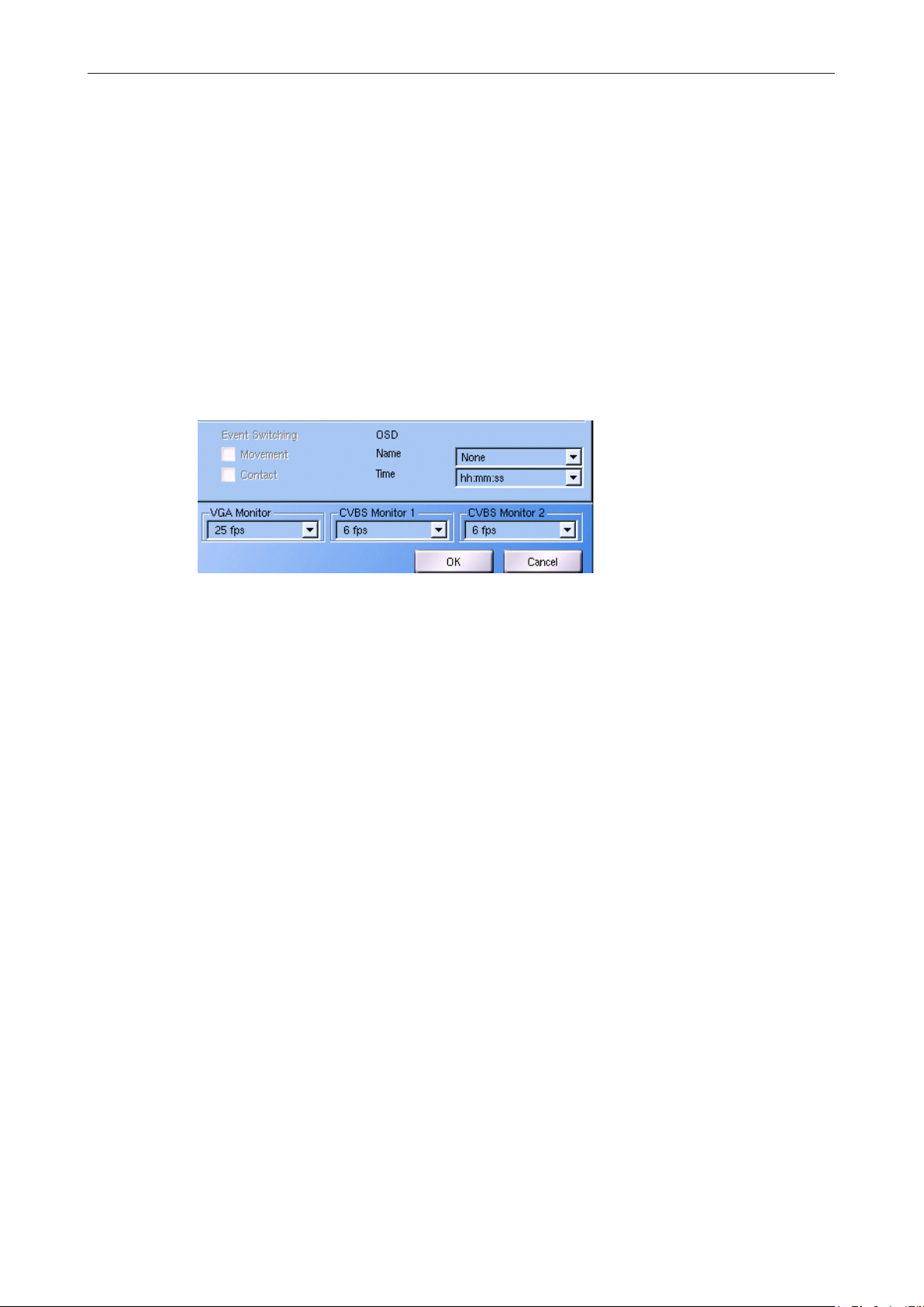
The frame rate automatically will be adjusted when an external application (e. g. PView)
establishes a PRemote connection to the recorder.:
VGA Monitor 6 fps
CVBS Monitor 1 6 fps
CVBS Monitor 2 25 fps
After breaking the connection the original settings will be restored again.
7.2.4 OSD display
The OSD function can blend in the camera name and the current time in the image displayed on a CVBS monitor.
¾ Select the relevant CVBS monitor (tab).
DMS 80 / DMS 160 / DMS 240 / DMS 240 HSR
Fig. 7-11
¾ Set the camera name or the camera description as Name.
¾ Set the format for the Time.
¾ Conrm with OK.
www.dallmeier.com 80

8 Network and PAS
8.1 Ethernet
The network settings of the device can be congured manually or automatically assigned
by a DHCP (Dynamic Host Conguration Protocol) server.
Note that...
... incorrect network settings (e.g. the allocation of an already used IP address) die may
result in malfunctions.
... the detected and available network speed is displayed in the Setup > System > Info >
Network dialogue.
... the bit rate off all IP cameras recordings is reduced when many IP cameras are used
with a too low network speed (e.g. 10 Mbps
... the default settings are used.
Use DHCP inactiv
Allow IP-Finder conguration activ
FQDN SSL-Certikate inactiv
IP Adress 192.168.2.230
Subnet mask 255.255.255.0
Data rate Auto
Host name system
Domain name dallmeier.com
DMS 80 / DMS 160 / DMS 240 / DMS 240 HSR
¾ Open the Ethernet/Tokenring dialog via Setup > Network >Settings > Ethernet.
Fig. 8-1
¾ Note the following explanations.
¾ Activate the required options.
¾ Deactivate the not required options.
¾ Conduct the manual or DHCP conguration, as described in the following chapters.
¾ Conrm with OK.
www.dallmeier.com 81

IP-Finder conguration
When this option is activated the IP address can be set via network with the Dallmeier
IP-Finder software. This option should be deactivated because of security reasons, if the
remote conguration is not necessary.
Data rate
The Data rate (network speed) can be set in manual as well as in DHCP conguration. The
standard setting Auto normally is sufcient.
FQDN SSL Certicate
This option is relevant for the browser access via network, if the SSL (Secure Sockets Layer) cryptographic protocol is used for secure data transmission.
When the option is deactivated the IP address will be used for the SSL certicate. When the
option is activated the FQDN (Fully Qualied Domain Name) will be composed of the Host
name and of the Domain name and used for the SSL certicate.
8.1.1 Manual conguration
The network settings must be assigned manually, if no DHCP Server is available.
DMS 80 / DMS 160 / DMS 240 / DMS 240 HSR
¾ Observe the designated and valid IP address ranges of the network.
¾ Ensure that the DHCP checkbox is deactivated.
¾ Enter the IP address.
¾ Enter the Network mask.
¾ Enter the Gateway address.
¾ Set the Data rate, if required.
¾ Enter the Host name (system name), if required.
¾ Enter the Domain name, if required.
¾ Deactivate the Allow IP-Finder network conguration checkbox if not required
¾ Conrm with OK.
The connection to the device is terminated and the new network settings are assigned.
8.1.2 DHCP
I order to automatically assign the network settings by a DHCP server, proceed as follows:
¾ Ensure that an active DHCP server is available in the local area network (LAN).
¾ Activate the DHCP checkbox.
¾ Set the Data rate, if required.
¾ Enter the Host name (system name), if required.
¾ Enter the Domain name, if required.
¾ Deactivate the Allow IP-Finder network conguration checkbox if not required
¾ Conrm with OK.
The connection to the device is terminated and the new network settings are assigned by
the DHCP server (pay attention to the lease duration).
www.dallmeier.com 82

8.2 PSTN/Terminal-Adapter
The functions for data transmission (PAS) via modem (PSTN) or Terminal Adapter (ISDN)
are not integrated in the current version of the recorder software.
8.3 Alarm hosts
An alarm host is an addressee of messages and alarms that can send by a recorder. The
individual conguration (connection type, message type and activation period) of up to 8
addressees is made in the Alarm-Hosts dialog.
¾ Open the Alarm-Hosts dialog via Setup > Network > Alarm Hosts.
DMS 80 / DMS 160 / DMS 240 / DMS 240 HSR
Fig. 8-2
The 8 alarm host will be displayed in a select list. They have to be congured as described
below before their activation.
Apply saves the current setting without the need to conrm and close the dialog with OK.
8.3.1 Selection and name
First an alarm host has to be selected in order to congure it. This is always made with a
left click in the alarm host list.
www.dallmeier.com 83

DMS 80 / DMS 160 / DMS 240 / DMS 240 HSR
Fig. 8-3
The name of the alarm host can be changed if necessary.
¾ Select an alarm host with a left click in the alarm host list.
¾ Open the virtual keyboard Change name.
¾ Enter a term without special characters as Name for alarm-host.
¾ Close the virtual keyboard with OK.
8.3.2 Connection
The specication of the connection type and the entry of the address data are made in the
Connection type section.
Take into account that the current recorder version supports message transmission via the
Ethernet interface only.
¾ Select an alarm host with a left click in the alarm host list.
¾ Select the transmission type Ethernet.
¾ Open the Ethernet/Tokenring dialog with Connection.
Fig. 8-4
www.dallmeier.com 84

DMS 80 / DMS 160 / DMS 240 / DMS 240 HSR
¾ Enter the alarm host’s IP-Address.
¾ Set the maximum duration of a connection attempt as Ping Timeout (seconds).
The connection attempt will be canceled when Ping Timeout is expired. After a break the
connection attempt will be started again and repeatedly (Interval). The interval and the
number of new connections attempts can be adjusted in the Interval settings dialogs.
¾ Open the Interval settings dialog with Interval.
Fig. 8-5
¾ Please not the GUI’s explanations.
¾ Please not the explanations below.
¾ If necessary make the required changes.
¾ Conrm with OK.
If options A or C have been selected the connection attempt will be tried until it actually is
successful and the message can be send to the alarm host.
If option B is selected the connection attempt will only be tried X times. Then the message
will be discarded or send to an alternative alarm host (see in the following).
8.3.3 Alternative alarm host
One alternative can be dened for every alarm host. The alternative alarm host will be adopted as addressee of a message if the original alarm host permanently is not reachable
(see above).
Fig. 8-6
www.dallmeier.com 85

¾ Select an alarm host with a left click in the alarm host list.
¾ Set the alternative alarm host with the Alternative drop down box.
The alternative alarm host will be displayed in the select list’s Alt. column.
Fig. 8-7
8.3.4 Connection check
The Alarm-Host check function allows a checkup of the connection between recorder and
alarm host by sending a test message. The successful transmission can be controlled at
the alarm host (PGuard) The recorder does not receive an acknowledgement.
¾ Select an alarm host with a left click in the alarm host list.
¾ Open the Alarm-Host check conguration dialog with Alarm-Host check.
DMS 80 / DMS 160 / DMS 240 / DMS 240 HSR
Fig. 8-8
There are three options to set the transmission time:
1. Activate the Interval radio button in order to send the test message in dened time intervals.
2. Activate the Point in time radio button in order to send the test message at a dened
point in time.
3. Click the Send button in order to send the message only once. A delay of up to 10 minutes can be set as well.
www.dallmeier.com 86

8.3.5 Messages
Which messages will be sent can be denes separately for every alarm host. Thereby take
into account that the single messages are combined to message categories. The message
displayed by the alarm host and the additional displayed information depend on the alarm
host’s conguration.
¾ Select an alarm host with a left click in the alarm host list.
¾ Open the Messages dialog with Messages.
DMS 80 / DMS 160 / DMS 240 / DMS 240 HSR
Fig. 8-9
¾ Select relevant message categories by activation of the corresponding checkbox.
¾ Please not the explanations below.
¾ Conrm with OK.
Alarm
This message will be send if the recorder starts or ends its alarm state.
The alarm state is triggered by the Start alarm contact IN function. It is stopped by the
corresponding contact IN functions or after the set alarm duration (System > Options >
Alarm duration) being expired.
Event
This message will be send if the recorder starts recording of an arbitrary camera because
of a movement event.
Array Contact
This message will be send if the recorder starts recording of a camera because of a contact
IN function (Start recording (recording mode Contact).
HDD Failure
This message will be send when a HDD read or write error is detected.
Housekeeping-Error
This message will be send if the system monitoring (housekeeping) detects an event of the
category “error“.
www.dallmeier.com 87

DMS 80 / DMS 160 / DMS 240 / DMS 240 HSR
Events of the category “error“ are:
• The I/O board could not be put into operation.
• The I/O board is ready for operation.
• The display could not be put into operation.
• The display is ready for operation.
• The CPU temperature cannot be determined.
• The CPU temperature can be determined.
• The internal temperature cannot be determined.
• Error during determination of the internal temperature
• The internal temperature can be determined.
• The external temperature cannot be determined.
• Error during determination of the external temperature.
• The external temperature can be determined.
• The revolution of the front fan cannot be determined.
• Error during determination of the revolution of the front fan.
• The revolution of the front fan can be determined.
• The front fan does not rotate anymore.
• The front fan rotates again.
• The revolution of the rear fan cannot be determined.
• Error during determination of the revolution of the rear fan.
• The revolution of the rear fan can be determined.
• The rear fan does not rotate anymore.
• The rear fan rotates again.
• The revolution of the HDD fan cannot be determined.
• Error during determination of the revolution of the HDD fan.
• The revolution of the HDD fan can be determined.
• The HDD fan does not rotate anymore.
• The HDD fan rotates again.
• The housing screw has been loosened.
• The housing screw has been screwed in.
• The housing cover has been opened.
• The housing cover has been closed.
• Power supply unit 1 failed.
• Power supply unit 1 is operational again.
• Power supply unit 2 failed.
• Power supply unit 2 is operational again.
Housekeeping-Sabotage
This message will be send if the system monitoring (housekeeping) detects an event of the
category “Sabotage“.
Events of the category “Sabotage“ are:
• The BNC terminal has been removed.
• The BNC terminal is ready for operation.
www.dallmeier.com 88

DMS 80 / DMS 160 / DMS 240 / DMS 240 HSR
Housekeeping-Systemmotoring
This message will be send if the system monitoring (housekeeping) detects an event of the
category “info“.
Events of the category “info“ are:
• The internal temperature is in the upper/lower/normal range.
• The external temperature is in the upper/lower/normal range.
• The CPU temperature is in the upper/lower/normal range.
• The average system temperature is in the upper/lower/normal range.
• The internal/external/CPU or average system temperature has reached the upper limit.
The recorder will be shut down.
• The revolution of the front fan is too high/too low/normal.
• The revolution of the rear fan is too high/too low/normal.
• The revolution of the HDD fan is too high/too low/normal.
Camera failure
This message will be send if fails or is working again.
Camera contact
This message will be send if the recorder starts recording of a camera because of a contact
IN function (Start recording camera (recording mode Contact)).
No Recording
This message will be send if no recording is triggered in a particular track in a dened
period. Relevant are cameras / tracks with the recording mode motion or contact. The
appropriate conguration is done in System > Options > Recording Timeouts.
SEDOR
®
-Alarm Sabotage
This message will be send if SEDOR® detects a sabotage event on a camera (defocusing,
turning, covering).
SEDOR
®
Error
This message will be send if SEDOR® detects an internal error.
Sensor contact
This message will be send if the sensor (sensor card SK6) detects a movement and thus
triggers a recording.
The current recorder version does not support this message (no SK6).
Overow exeeded
This message will be send if more then 80% of the video memory is occupied.
Overow undercut
This message will be send if the occupation of the video memory falls below 80% again (e.
g. when tracks have been deleted).
Secure track saved
This message will be send if the recorder saves a Secure Track from being overwritten. It
is irrelevant which event (Alarm or Contact IN) triggers the saving function.
www.dallmeier.com 89
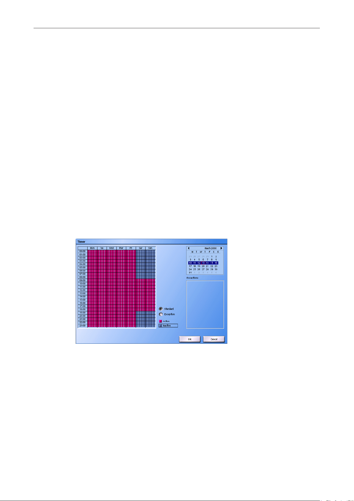
System
This message will be send in case of certain errors in the complete system or if status messages of a system component arrive at the recorder.
• camera failure
• write or read fault error of a HDD
• unknown software problem, recorder does not react or reacts only very slowly
• Housekeeping error event
• Error message of UPS
• Initialization error
• RAID (internal) error
UPS
The uninterruptible power supply unit (UPS) sends a message that is forwarded to the
alarm host.
8.3.6 Timer
After its activation (see in the following) the messages will be sent to the alarm host anytime
(24/7). Differing from this standard conguration it is possible to limit the host’s active time.
DMS 80 / DMS 160 / DMS 240 / DMS 240 HSR
¾ Select an alarm host with a left click in the alarm host list.
¾ Activate the host timer with the Timer active checkbox.
¾ Open the Timer dialog with Timer.
Fig. 8-10
¾ Set the Active and Inactive times as described in the Camera timer section (see above).
¾ If necessary set Exceptions as described in the Camera timer section (see above).
¾ Conrm with OK.
www.dallmeier.com 90

8.3.7 Activation
After its conguration the alarm host must be activated.
¾ Select an alarm host with a left click in the alarm host list.
¾ Activate the corresponding checkbox in the Active column.
Fig. 8-11
8.3.8 EBueS
EBueS (uniform image transmission system / Einheitliches Bildübertragungssystem) is a
standardized transmission system for messages and images between a recorder and an
alarm host.
The recorder can send all messages concerning states and events (see chapter Alarm
hosts / Messages). Which messages actually will be processed and displayed by EBueS
depends on the EBueS server conguration. In order to avoid needless network trafc only
relevant messages should be sent.
DMS 80 / DMS 160 / DMS 240 / DMS 240 HSR
The EBueS… will only be displayed when the appropriate function has been activated.
After the activation of EBueS the ZENTRALE8 alarm host is prepared for this function.
¾ Select alarm host number 8.
The connection type Ethernet will be set automatically.
The EBueS… will be activated.
Fig. 8-12
¾ Click EBueS….
www.dallmeier.com 91

DMS 80 / DMS 160 / DMS 240 / DMS 240 HSR
The Settings for EBueS connection dialog will be displayed:
Fig. 8-13
¾ Enter the EBueS server IP Adress.
¾ Enter the FTP user name.
¾ Enter the FTP password.
¾ Enter the Remote target directory if necessary.
¾ Check the settings by sending a test message.
¾ Conrm with OK.
The EBueS alarm host can be congured subsequently as described above.
8.4 Parameter backup
The network parameter can be saved on an external medium for backup or editing.
8.4.1 Export
The les saved during the export of the network parameter contain
• system name (see above)
• alarm hosts
• Ethernet
• PSTN
and where applicable time server, UPS, network printer, etc.
www.dallmeier.com 92

¾ Open the Export network les dialog via Setup > Network > Import/Export > Export.
Fig. 8-14
¾ Select the relevant medium as Target.
¾ Conrm with OK.
8.4.2 Import
DMS 80 / DMS 160 / DMS 240 / DMS 240 HSR
Files that have been saved or edited on a PC can be integrated via Import again.
¾ Open the Import network les dialog via Setup > Network > Import/Export > Import.
Fig. 8-15
¾ Select the relevant medium as Source.
¾ Conrm with OK.
www.dallmeier.com 93

9 Serial Interface
The serial interface allows the connection and the communication with external devices.
9.1 Setting
¾ Open the Serial Interfaces dialog via Setup > Interfaces > Serial.
DMS 80 / DMS 160 / DMS 240 / DMS 240 HSR
Fig. 9-1 : Serial Interfaces dialog
¾ Set the relevant Interface.
¾ Set the Function.
¾ Set the connection parameter, if necessary.
¾ Finally conrm with OK.
9.2 Functions
The available functions of the interface depend on various software and hardware options. The
scope of functions depends on the ordered version, not on the content of the documentation.
None
The interface is deactivated.
Commanding
This function allows the recorder to be controlled by an external application / device via
the serial interface (DaVid protocol). Control commands are only received, however, no
conrmation is returned.
Mouse
This setting allows the connection of a serial mouse. This is only advisable if mouse control
over a long distance (up to 100 m) is required. This can not be achieved using a PS/2 or
USB mouse.
www.dallmeier.com 94

DMS 80 / DMS 160 / DMS 240 / DMS 240 HSR
Transparent data channel/Direct camera control
Using this function data can be sent via the recorder to another device. The data then arrive
at the receiver in exactly the same form as they were sent by the transmitter (transparent
data channel).
This is used, for example, to send control signals from PView via LAN to the recorder. This
then forwards them to a controllable camera via the serial port.
In the opposite direction, conrmation signals from the camera are read at the serial port
and sent via LAN to PView.
DNI (external system)
This setting allows an external system to be connected for example an automatic teller machine (ATM), access control system or a Huth cash desk via a Dallmeier Network Interface
(DNI-1).
UPS
This function allows communication with an uninterruptible power supply unit (UPS). This
means that messages can be sent from the UPS (for example charge status of the battery)
to the recorder where they can be output or processed.
DNI (camera control)
This function allows the connection of an external control desk or a dome camera via a
Dallmeier Network Interface (DNI-1).
www.dallmeier.com 95

DMS 80 / DMS 160 / DMS 240 / DMS 240 HSR
10 Contact IN
The contact inputs allow the control of the recorder with external devices.
¾ Open the Contact In dialog via Setup > Interfaces > Contact IN.
10.1 Global and camera-related contacts
First of all only the freely congurable global contacts will be displayed.
The camera-related contact inputs are displayed if you check the Show camera contacts
checkbox.
Fig. 10-1 : Show camera contacts
The camera contacts can be preset using Start camera. Therefore the recording of the
relevant camera is started if the required recording settings have been made.
If you do not wish to record a camera using the Contact recording mode, the function can
be changed in the same way as the global contacts.
10.2 Make and break contact functions
First of all only the conguration of the Make contact function (function n.o.)of the contact inputs will be displayed. The functions that are executed when the contact switches
(normally when it closes) are dened here.
In addition, however, functions can also be dened that are executed when the contact is
released (normally when it is opened).
The conguration of the functions for the Function n.c. is displayed when the show
Function n.c. checkbox is checked.
www.dallmeier.com 96

DMS 80 / DMS 160 / DMS 240 / DMS 240 HSR
Fig. 10-2 : show function n.c.
The function of a camera contact (break or make contact) can be set in Interfaces >
Camera Contacts.
10.3 Setting
Every contact input can be assigned four functions for the Function n.o. and the Function
n.c.. These are executed in order when the contact is switched or released.
A B
Fig. 10-3 : Select function
¾ Left-click into the line of the relevant Function (A).
¾ Select a function from the drop-down box (B).
C
Contact parameters also have to be declared for some functions. This is indicated by displaying an orange button next to the function name.
¾ Click on Contact parameters button (C).
The Contact Parameters dialog is displayed.
¾ Make the required settings.
¾ Conrm with OK.
www.dallmeier.com 97

10.4 Functions
The available functions of the interface depend on various software and hardware options. The
scope of functions depends on the ordered version, not on the content of the documentation.
None
No function selected.
Shut down recorder
The recrder will be shut down without taking further conditions into account.
Start alarm
This function activates the alarm state of the recorder. The alarm duration can be set via
Setup > System > Options > Alarm Duration.
Stop alarm
The recorder is in alarm state. The contact function Stop alarm allows the alarm to be
stopped before the end of the alarm duration.
After stopping the alarm state, the secure tracks are saved and new secure tracks created.
The tracks are locked and must be released separately.
DMS 80 / DMS 160 / DMS 240 / DMS 240 HSR
Save Secure-Tracks (all)
Active recording into the secure tracks is stopped. The secure tracks are saved. Recording
is continued in new secure tracks.
Extend alarm
The recorder is in alarm state. If the Extend alarm contact function is triggered before the
end of the alarm duration, the alarm state will be extended indenitely (or until the corresponding track is full).
The alarm state can then only be stopped by the Stop alarm contact function.
Delete alarm
The last alarm state will be canceled. Saved secure tracks will be deleted. Locked tracks
will be released again and the images of the track will be deleted.
Send message with value
This contact function causes a message to be sent to the alarm host. A binary value can be set in the
Contact Parameter dialog. This value is sent together with the message and can be freely
interpreted by the alarm host.
Start recording (recording mode Contact)
This function starts the recording of one or more cameras that are dened with recording
mode Contact.
Which camera is relevant is dened in the Contact Parameter dialog.
Stop recording (recording mode Contact)
This function stops each recording that is still active (timer can be expired) that was triggered by Start recording (recording mode Contact). Which camera is relevant is dened in
the Contact Parameter dialog.
www.dallmeier.com 98

DMS 80 / DMS 160 / DMS 240 / DMS 240 HSR
Quit pause of all alarm-hosts
This contact function allows to activate all congured alarm hosts. This contact function is
no counterpart to the Pause all active alarm-hosts contact function. It does not matter if the
alarm host was deactivated by Pause all active alarm-hosts or before.
Pause recording (all recording modes)
This function allows to stop or pause each active recording of one or more cameras.
The recording mode of the camera does not play a role for this function. Recording will be
stopped for Permanent cameras. If the recording mode of a camera is Contact or Motion
detection, the next event will not trigger the recording.
Which camera is relevant is dened in the Contact Parameter dialog.
Quit recording pause (all recording modes)
This function starts/activates each recording that was stopped by Pause recording (all
recording modes).
The recording mode of the camera does not play a role for this function.
However, attention must be paid to the fact that a recording may not occur immediately with
recording modes Contact or Motion detection.
Which camera is relevant is dened in the Contact Parameter dialog.
Start Camera
This function starts the recording of one camera that is dened with recording mode
Contact.
Which camera is relevant is dened in the Contact Parameter dialog.
Stop Camera
This function stops the recording that is still active (timer can be expired) that was triggered
by Start recording Camera (recording mode Contact).
Which camera is relevant is dened in the Contact Parameter dialog.
Live display camera
Display of the images of a camera in the 1x1 split. The images are also displayed if a display sequence is dened (via System > Display > Monitors > Sequencer) and active.
The duration of the display of that camera depends on the switching speed, which is set
under Setup > System > Display > Monitors > Sequencer. This means that a camera is
diaplayed until a switching is triggered manually or by the sequencer.
Which camera is relevant is dened in the Contact Parameter dialog. Every activated
camera can be selected. It does not matter if the camera is connected or congured for
recording.
Disable remote access (LAN, ISDN, modem)
This contact function breaks all active connections of applications or users that do not have
the right Network access with contact. New connection requests are rejected.
This has no impact on users dened as administrators. This user group has always all
rights.
www.dallmeier.com 99

DMS 80 / DMS 160 / DMS 240 / DMS 240 HSR
Day/Night Mode (analogue camera, UTC)
This function allows the control of day / night mode switching of a camera (analogue,
UTC capable). It is irrelevant thereby if the camera is dened as an UTC camera in the
Recording Settings dialog.
Which cameras are relevant and in which mode they should switch is dened in the
Contact Parameter dialog.
Reboot
This contact function causes a reboot of the recorder.
Switch Recording Quality
This function is relevant for cameras with the recording mode Switching by contact. It
switches the recording quality to High Quality.
Which camera is relevant is dened in the Contact Parameter dialog. Every activated
camera can be selected. It does not matter if the camera is connected or congured for
recording.
Reset Recording Quality
This function is relevant for cameras with the recording mode Switching by contact. It
switches the recording quality to Normal Quality.
Which camera is relevant is dened in the Contact Parameter dialog. Every activated
camera can be selected. It does not matter if the camera is connected or congured for
recording.
10.5 Conguration of camera-related contacts
The camera-related contact inputs can be freely congured as Makers or Breakers.
¾ Open the Camera Contacts dialog via Setup > Interfaces > Camera Contacts.
Fig. 10-4 : Camera Contacts conguration
¾ Make the required settings.
¾ Conrm with OK.
www.dallmeier.com 100
 Loading...