

Page 1
ENGINEER
Operating Instructions
Caution - Electrically operated product. Please read and follow
instructions to insure safe operation and handling.
Page 2

OVERVIEW
The ENGINEER THROTTLE is an
integ rated circuit design, full feature,
momentum throttle. The stand ard
ENGINEER pro duces 13 volts DC with
a maximum curren t of 5.0 amperes.
The GAUGE-1 ENGINEER produces
18 volts DC with a maximum current
of 4.0 amperes. In ad dition to its meter
instrumentatio n and adjustable pulse
generation circuitry, the ENGINEER
allows the user to vary both the
throttle speed response (momentum)
and the service brake response. This
variability of both throttle and brake
resp onse permits realistic simulation
of handling characteristics ranging
from light engine movement to full
tonnage trains. Interlocked reverse is
also a standard feature of the
ENGINEER. Interlocked reverse
requires the train to stop before the
reverse switch becomes functional.
The ENGINEER is equip ped with a
regulation circuit which maintains a
constant output vo ltage and therefo re
constant locomotive speed. The
ENGINEER's pulse generatio n circuitry
allows adjustment of p ulse height to
permit matching of pulses to individual
locomotive motor starting
requirements. The pulse frequency is
varied automatically according to the
demand established by the
ENGINEER's output voltage level.
The ENGINEER has a four position
brake switch which simulates most
operating functions including
acceleratio n, deceleratio n and/or
braking and continuous running. This
brake switch, tog ether with the
reverse interlo ck feature are
combined in the optional
WALK-A-ROUND controller to permit
walk around control, with memory, of
the ENGINEER from any number of
remote p lug in locations.
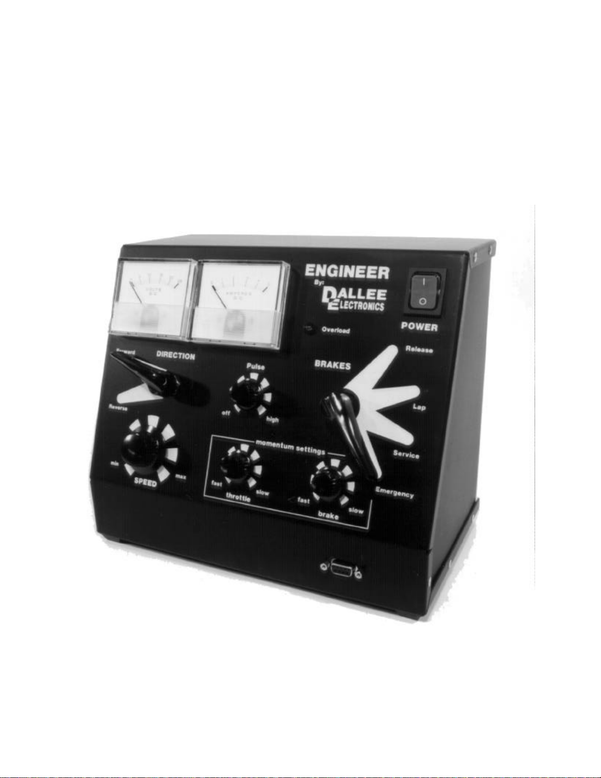
DESCRIPTION AND LOCATION OF
COMPONENTS AND CONTROLS
On the rear face o f the ENGINEER
you w ill find the power cord, a
resettable circuit breaker and a
barrier strip with two terminals. These
two terminals are fo r the output to the
track. There are no other outputs
provid ed as it is our judg ement that all
power in the throttle should b e
reserved for output to the track and
any accessories should b e connected
to a sep arate power source.
The voltmeter is located in the upper
left area of the face p anel and is used
to mon itor track voltage. Adjacent to
the voltmeter and to its right is the
ammeter which is used to monitor the
current flow to the track (load ). To the
right of the meters you will find a red
indicator which is used to show
maximum current co nditions. During
short circuit or currents in excess of
maximum, this indicator will illuminate.
If the overload continues the ampere
outp ut will become less than when the
short/overload occurred (this is known
as foldback current limiting) and the
outp ut voltage will gradually decrease
to a low setting . This will eliminate
jack rabbit starts which would
otherwise occur when the overload is
corrected.These indications depict
prop er function of the internal,
electronically limiting, output current
regulato r.
In the upper right corner is the power
switch which will glow green when the
ENGINEER is "ON".
Belo w the meters, at the left, is the
reversing switch. This switch is like a
DPDT type with out center off. Its two
positions are labeled FORW ARD and
REVERSE and its function is
interlocked so that directio n can only
be changed when throttle output is at
zero voltage, indicating a full stop.
To the right of the reversing sw itch
and at about the center of the panel is
the PULSE control which allows the
2
Page 3

matching of throttle pulse output to
the starting characteristics of the
moto rs in the various types of your
locomotives. Rotating this control
clockwise increases pulse height.
Pulse frequency is automatically
varied accord ing to demand
established by throttle output voltage.
With the PULSE control in full
counter-clockwise position the pulse
circuit is off.
Belo w the reversing switch is the
throttle SPEED control which
determines the output vo ltage to the
track and consequently loco motive
speed. While clockwise rotation
increases speed , it may be more
convenient to set th is co ntrol at a
maximum speed setting and use the
brake switch for actual o peration.
IMPORTANT--- T here is no "OFF"
position on the sp eed control. Full
counter-clockwise results only in a
minimum output wh ich can allow
locomotives to creep. To b ring a
locomotive to a co mplete stop the
BRAKE switch must be used .
To the right of the SPEED control and
centered on the low er row of controls
is the T HROTTLE RESPONSE or
"mo mentum" control. T his control
adju sts the time frame required for
outp ut voltage to change from one
speed setting to another . Clockwise
rotatio n inc reases the time frame and
therefore longer delay (slower
resp onse). The right side of the panel
is devoted to the braking system and
contains tw o controls. The upper
control is th e actual BRAKE sw itch
which, with its fou r positions, is th e
heart of the ENGINEER's o perating
functions. These four positions are
labeled RELEASE, LAP, SERVICE, and
EMERGEN CY. With the BRAKE switch
in RE LEASE the SPEED control and
its momentum adjustment, also the
pulse generation circuitry, are
connected to the CAB output and the
train will accelerate to whatever
speed is set on the SPEED control.
The LAP position is similar to a cruise
mod e where the train will maintain the
speed at which LAP was selected.
SERVICE is an actual b raking
application. When SERVICE is
selected , the output voltage to the
track is reduced, which causes the
train to slow down to an ultimate stop.
The rate at which this slow dow n
occurs is varied by the BRAKE
RESPON SE control. The
EMERGEN CY position provides a rapid
stop . T he BRAKE RESPONSE control
located directly below the BRAKE
switch is an additional mo mentum
adju stment which varies the
deceleratio n available durin g a service
brake application. Clockwise rotation
of this control increases the response
time of the braking application, taking
longer to slow down and thereby
simulating a heavier train. It is also
possible to "LAP" the brakes by
alternating the brake switch betw een
the SERVICE and LAP p ositions. This
will simulate the action of an "air" train
brake.
THROTTLE OPERATION
Now that you are familiar with the
location and functio n of the various
components and controls of your
ENGINEER, lets hook up to the layout
and practice running a locomotive.
Connect the CAB output terminals o n
the back of the ENGINEER to the
track using your existin g pow er
distributio n system. We recommend
the use o f #16 gauge or heavier wire,
depending o n the size of your layout
and the length of the wire runs out to
the track. A simple rule to follow: the
longer the wire and the larger the
load(current d raw), the heavier the wire
should be to minimize line loss(voltage
drop ) between the throttle and the
track. It may be advisable to use wire
as large as #8 or #10 to get th e full
use of the high current capabilities of
your ENGINEER.
Put the BRAKE switch in
3
Page 4

EMERGEN CY and rotate all controls
to their full counter-clockwise position.
Connect the power cord to a
grounded household line o utlet
(110-120 VAC) and push the top part
of the power switch. The green lamp
should illuminate. If it does not, ch eck
the power cord and plug, the outlet
receptacle and the household line
circuit. With power on the ENGINEER,
the first step is to adjust the pu lse
circuit to match the motor in the
locomotive selected.
1) Check - - - b rake in
EMERGEN CY and all
controls full
counter-clockwise.
2) Release brake and rotate
pulse contro l clockwise until
locomotive just begins to
creep. If pulse is set too high
the motor will b e n oisy. It
may be necessary to
increase the SPEED contro l
very slightly in order to get
the pulses to turn on.
3) Set both throttle and brake
resp onse to about 9 or 10
o'clock to provide some
momentum delay.
4) Increase speed control
clockwise - - - acceleration
should be smo oth. Set
speed control at 12 o'clock
and let sp eed increase.
5) Make a service brake
application to a full stop and
watch for a smooth
deceleratio n. Watch meters
for evidence of pulses as
stop is approached.
6) Release brake and watch
start again.
7) Brake again to a full stop.
8) If the start and stop are
sudd en the pulses are
prob ably set too low. If the
start and stop are jerky or
the motor is noisy the pulses
are set too high and should
be lowered. (Note: 3 pole
moto rs will always be
somewhat jerky in operation
as compared to a 5 or 7
pole motor) Also, some
mechanisms just are not
smooth enough to
appreciate th e full effect of
the pulse circuit.
9) Fine adjust the pulses un til
you are satisfied with the
smoothness of op eration.
10) Pulse settings w ill vary from
locomotive to lo comotive
because of d ifferences in
moto r and gear tolerances,
however these settings are
unique and should b e
repeatable every time a
specific locomotive is run.
With the p ulses adjusted to match the
locomotive, lets practice actual
operation. Initially we will operate just
the locomotive so the respo nse
settings (both throttle and brake)
should be at or close to minimum. Try
about 9 o'clock for now. Let the
speed control remain at the 12 o'clock
position. With th e reverse switch in
the forward position we should be
read y to proceed. Release the brakes
and lets move on down the track.
Note that the start is smooth and
acceleratio n is gradual up to the
speed sele cted. Check the voltmeter
and see w hat voltage is actually
reached at this setting. Change the
speed control to a higher setting and
watch as the voltage and speed
increase. To slow down we have two
choices. We can lower the speed
control o r we can apply the brakes.
Leave the speed control set at about
3 o'clo ck which sh ould be around 12
volts (15 volts on the GAUGE-1). Shift
the brake switch to SERVICE. Voltage
will immediately reduce at whatever
brake response is set and the
4
Page 5

locomotive w ill slow dow n. If you stay
in SERVICE you w ill come to a
complete stop. Release the brakes
again and accelerate b ack up to
about 12 volts. This time make a
SERVICE application down to 8 volts
and move the brake switch to LAP.
The locomotive will continue to run at
the 8 volt speed. Make another brake
application d own to 6 vo lts and return
to LAP. Note that the loco has now
settled at a lower speed. To increase
speed merely release the brakes and
accelerate to the voltag e required,
then select LAP.
If you were dragg ing a train instead of
only a locomotive, the time needed to
accelerate or to stop will depe nd on
how he avy the train is. Change both
resp onse c ontrols to about 12 o'clock
which simulates a medium weight
train. Release the brakes and note
that it takes considerably longer for
the train to reach the selected speed.
Make a SERVICE app lication and also
note that slow down takes
considerably long er. If this is an
extremely heavy freight drag the
acceleratio n would be very gradual
and when stop ping it w ould b e like
being shoved into the next county.
Adju st both throttle and brake
resp onse to the maximum clockwise
settings and try running your train
now. Note the wide range of operating
characteristics you are able to
simulate with th e adjustments
available on your ENGIN EER.
Try once mo re w ith the momentum
adju stments set to positions more in
line with yo ur usual trains. When
demonstrating the ENGINEER at
show s we frequently use a throttle
resp onse of about 11 o'clock and a
brake response of ab out 9 or 9:30.
Think of the voltmeter as a
speedometer. Set the SPEED control
at some maximum point, release th e
brakes and get your train headed out
of tow n. Since the signals have been
clear w e can run at the speed limit. As
we round a curve there is a yellow
signal telling us to slow down to
approach speed. Make a SERVICE
application with the brake switch to
bring the train speed dow n and then
select the LAP position. As we
approach the next sig nal we see a
red and must prepare to stop . Make a
series of brake applications, returning
the brake switch to LAP each time.
This will reduce speed to a low level
but will maintain continuous forward
movement. Rep eat SERVICE and LAP
as often as necessary to achieve a
smooth and realistic approach and
stop . One final SERVICE application
should stop your train exactly where
you wanted it. If you missed the stop
point, try again. With practice you will
beco me an accomplished engineer
with your ENGINEER.
WALK AROUND OPTION
The ENG INEER is equip ped with a 9
pin jack on the front where the
optio nal hand control for walk around
operation plugs in. The hand control
duplicates the reverse, brake and
both response contro ls of the
ENGINEER. The hand control has a
ten foot cord w ith the correct plug.
Any number of 9 pin jacks can be
located around the layout as long as
they are parallel wired to a plug back
at the ENGINEER. To use the hand
control to operate the ENGINEER:
1) Reverse switch o n the
ENGINEER in FORWARD.
2) Preset PULSE adjustment.
3) Preset SPEED control.
4) Set THROTT LE
RESPON SE on the
ENGINEER to minimum.
5) BRAKE switch on the
ENGINEER in LAP.
6) BRAKE switch on hand
control should initially be in
EMERGEN CY.
7) Plug the hand control into
the 9 pin panel jac k and
5
Page 6

operate with the brake
switch and other controls,
same as if they were on
the ENGINEER.
Because only the contro l functions
are remoted to the hand control, all
power to the train continues to come
from the ENGINEER which remains
connected to the track. If you unplug
the hand unit, con trol returns to the
ENGINEER. If your train is in motion
when you unplug, the ENGINEER will
continue this motion because the
brake switch is in LAP. If you were in
reverse when yo u unplug you will
continue in reverse even though the
ENGINEER is in forward be cause of
the interlock feature of the reverse
switch.
ONE FINAL C OMMENT:
The black finish of the ENGINEER is a
powder coating which makes the
application of the white lettering and
art work very difficult to apply. We
have taken great care to protect this
lettering how ever because of the
powder coat base the lettering is
subject to scratching. PLEASE
HANDLE WITH CAR E.
246 W. Main St., Leola, PA 17540
(717) 661-7041
WALK-A-ROUND
connections
5 4 3 2 1
Reverse Switch
1 - 2
4 - 3
Release
Brake (Emergency)
4 - 5
With SOUND controller installed :
9 - 7
Bell
Whistle
9 - 8
In normal positions, all connections are "OPEN". This means "LAP" and "Forward".
When connecting 4-5 emergency brake application will occur, having a series
resistance (such as found in our hand controller) will cause a slow braking effect.
Connecting 4-3 will "RELEASE" the brakes and allow accelleration at the "throttle"
response rate to the "SPEED" setting. Connecting 1-2 places the ENGINEER in
"Reverse"
If your ENGINEER is equipped with our SOUND CONTROLLER for our In
Locomotive DC Sound System, then terminals 7-9 are internally connected. As
shown by connecting 9-8 the WHISTLE signal is transmitted. Connecting 9-7 the
BELL signal is transmitted. Terminals 7, 8, and 9 together signals both the WHISTLE
and BELL. When the ENGINEER is set for zero volts output and a WHISTLE or BELL
signal is sent. The overload indicator ma y flash momentarily, this is normal.
9 8 7 6
as viewed from the front
of the ENGINEER
DO NOT short any terminals to others that are not to be connected as internal
damage will occur!!
6
 Loading...