

Page 1

IN LOCOMOTIVE ELECTRIC SOUND SYSTEM
for various track power by
CAUTION:
this possibility. Discharge yourself to an electrical ground (outlet cover screw) before removing this device from
its anti-static bag. Please read instruction sheet completely before attempting to install and operate this
product. Save the anti-static bag for possible reuse of storing or shipping the sound unit!
OVERVIEW: This device is an electronic, self contained, sound system for installation in model
electric locomotives that are designed to operate with conventional DC track power, digital (DCC)
or other types of command control systems including radio with either track or battery power, also
as a stationary sound unit. Because of its dimensions (2.7" x 0.9" x approx. 0.5" high) the sound
system may be limited to installations in some powered units making the need for use of a
"dummy" unit or a trailing car. An alternative installation under the layout is also possible including
the use of our TRAK-DT devices to switch the sound through multiple speakers so as to follow
the movement of the train. A drawing for this application is in our Model Railroaders Wiring Guide.
An on/off switch (not included) must be used to power the sound unit on and off in some
applications. The audio amplifier can produce one watt of power which is in excess of what most
small speakers can handle. The speaker impedance must be 8 ohms or higher. Sound volume is
adjustable. Refer to our catalog for available speakers. If space permits, the optional oval
speakers (Items 662, 664, 665), which are higher wattage speakers, are the best choice.
Sounds produced include user controlled horn, bell f orce cooling fans and main sounds on/off
(leaves the main sounds off while allowing for horn and bell operation). Non-user co ntrollable
sounds brake release and electric cooling fans sound. These automatically operate. The cooling
fans can be manually controlled.
This sound system, when used with conventional DC track power, requires the use of our
LocoMatic™ Controller (Item 755) to operate the horn, bell, force co oling fans, and main sounds
on/off. DCC and other command control operators can use remote functions on their systems to
activate the same functions. For stationary installations, these functions can be accessed by
switches. Radio control with fixed track power or on board batteries would be similar to DCC
installations and large gauge (where you ride the locomotive) would be similar to a stationary
installation.
INSTALLATION INSTRUCTIONS: The sound system consists of a printed circuit board, a
speaker, five 2-pin connectors with wires and two 3-pin connectors with wires. A CHOKE (item 70
or 703 depending on motor power requirements), no t included, is required for DC track power
installations.
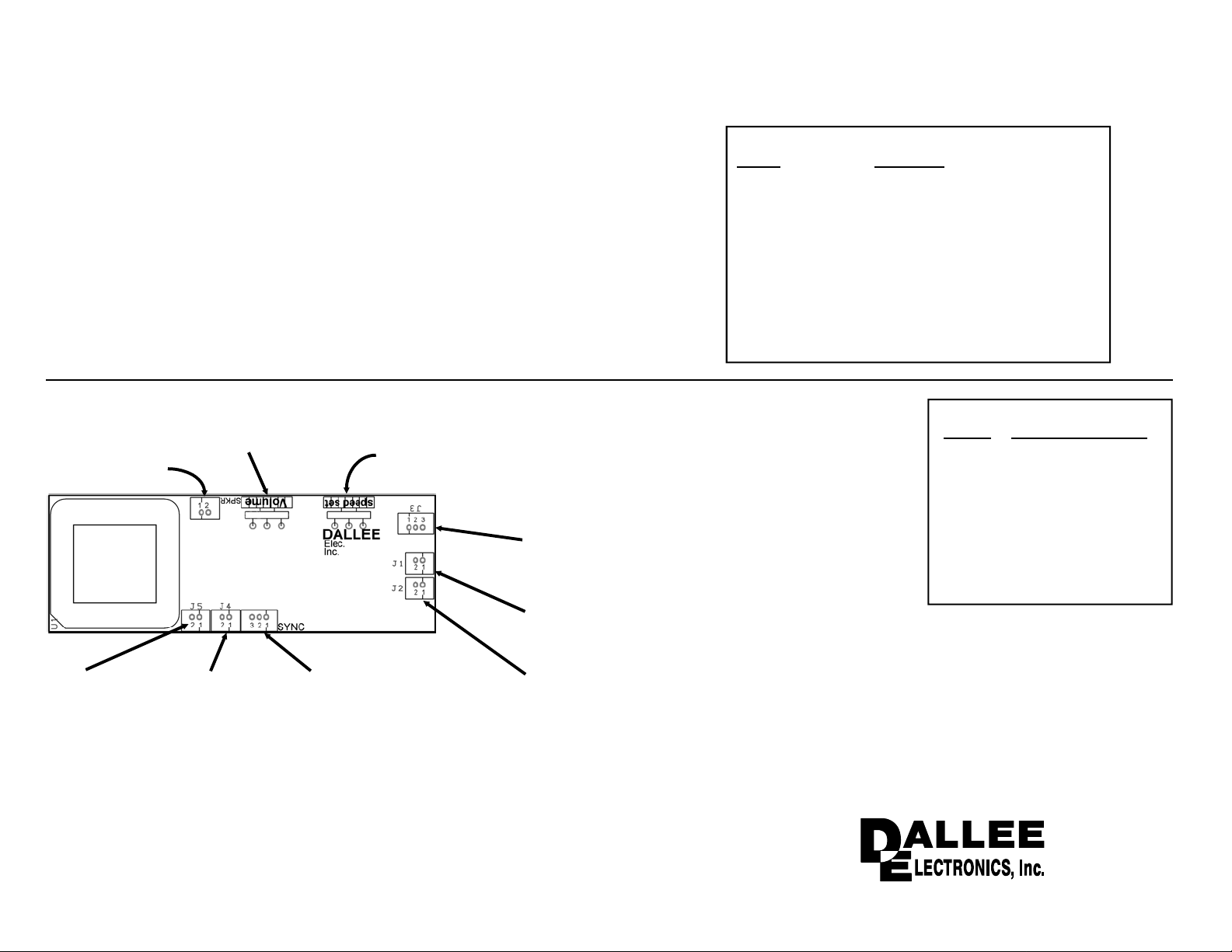
Refer to the drawing on page 2 to familiarize yourself with the connectors and controls on the
sound board. Then refer to the specific instruction sheets for the type of installation you intend to
make. Before proceeding with the installation read the balance of the instructions carefully so you
will be completely familiar with what is required and what sounds you should hear.
The circuit board should be mounted so that at minimum, the volume control is accessible either
through the frame or via a hatch or a hole in the locomotive body shell. Be certain that the
components on the circuit board do not come in contact with any metal objects as such contact
can destroy the sound system. The speaker should be mounted as per available space bearing in
mind that sound reproduction is enhanced when a speaker is properly enclosed and baffled.
If a DC locomotive is not moving, there is no track power, therefore to have sound it is necessary
to have a separate power supply for the sound system. For in locomotive use, this separate
supply is a battery. We suggest the use of one 9 volt or 6 AA or 6 AAA batteries in series to
maximize volume potential and battery life. Rechargeable batteries can be used. When
connecting the battery (DC) power leads be absolutely certain that w ires connect to the proper
DC input leads.
This device can be damaged by static discharge. Please exercise care during installation to avoid
DCv3 rev8
If any connections are not done properly, especially the power connections, you will damage the
sound system. This type of damage is not covered under any warranty. The sound system is
thoroughly tested and inspected before packing to insure proper fu nction. There is a minimum
charge of $35.00 plus s/h for repair.
SOUND INFORMATION:
Cooling Fans (Electric): sounds range from idle (silent - no fans operate when not running) to
full fan rpm. With no power to the track / motor the sound system will produce no sounds. As a
throttle is advanced to put the locomotive in motion, a brake release will sound (see below) and
the electric fans will accelerate to full rpm. With our LocoMatic™ Controller (#755), activating the
ALT and F3 buttons simultaneously (and then releasing) will direct the sound system to ramp the
fans to full RPM regardless of track / motor voltage. Activating both buttons again will release the
sound system to return to the correct fan setting. This feature allows the simulation of more
cooling when sitting after a heavy load run or "pumping air" in a standing train. This full fan RPM
feature is available to other users either by a switch or with a remote function. The cooling fans,
air pops, and brake release sounds can be turned off without turning off the sound system. This
way you can still activate the Horn and Bell. With our LocoMatic™ Controller, use ALT F4 as a
push on, push off. For other receivers or stationary, a function or single pole switch will suffice.
BRAKE RELEASE: sound is produced when the throttle is advanced from the idle position. This
brake release should always precede locomotive movement. For DC operators, this requires
approximatly 1.5 to 2 volts of input voltage to sense a running mode for the brake release to
sound.
HORN: sound is controlled by the HORN button on the LocoMatic™ Controller, by a momentary
push button or by remote function, dependent upon the type of installation. The HORN will sound
as long you are holding the control on. This will allow you to actually play the sound as on a real
locomotive. DCC and similar systems will have a sound delay equivalent to system response
time.
BELL: sound is controlled by the BELL button on the LocoMatic™ Controller, by a toggle switch
or by remote function, dependent upon the type of installation. The sound system includes a
routine which ignores intermittent BELL requests, resulting in a delay when activating or
deactivating the BELL. With the LocoMatic™ Controller you depress and release the BELL button
to turn on the BELL and then again depress and release the button to turn the BELL off. Toggle
switch or remote function control does not require the PUSH ON - PUSH OFF sequence.
SPEAKER MOUNTING: The speaker generally should be mounted so that the sound can
actually "get out" of the locomotive. A hole in the floor or fuel tank is acceptable but open grills or
a doorway may be a better choice as the sound can exit upward rather than down toward the
track. In some cases, particularly with plastic body shells, just mounting the speaker against the
shell will be adequate as the vibrations of the shell can enhance the sound. Enclosing the
speaker in a chamber will also enhance sound reproduction. A very simple enclosure can be
made with a tube. The longer the tube the better the speaker will reproduce low frequency sound
which is inherent in electric cooling fanss. It is usually best to seal the end of the tube, so there
are no air passages to the rear of the speaker, thus creating a sound chamber. By carefully
sealing all openings it may be possible to use the entire body shell as a sound chamber. A simple
wall behind the speaker may be all that is possible or perhaps all that is needed.
Speakers can be attached with double sided tape, with glue or with "hot melt". Enclosures can be
made with plastic, wood, card stock or even metal. Film cans or medicine bottles make excellent
sound chamber enclosures for small diameter speakers. Attachment with "hot melt" is
advantageous as the "hot melt" can be used as a gap filler when creating an enclosure.
A second speaker, wired in series with the main speaker, can also enhance sound quality and will
1
Page 2
permit a higher volume without damage to the individual speakers. A tube with a speaker at each
end or a speaker in a doorway at each end of a body shell is an excellent approach. A four
speaker approach will yield the highest volume while still maintaining the 8 ohm minimum
requirement. Drawings for this are included in the speaker instructions.
Speaker enclosure is an art and experimentation is definitely in order for your installation so a s to
gain the maximum benefit of the superb sound quality available in this sound system.
GENERAL OPERATING INFORMATION:
VOLUME ADJUSTMENT: should be set as desired for your application. Please remember that
the amplifier can produce more power than a small speaker can handle and that the sound will be
louder if the speaker is properly enclosed and baffled. If you are using batteries, the louder the
volume the shorter the battery life.
NOTCH ADJUSTMENT: full clockwise for standard 12 volts to the track / motor. Rotate the
control CCW for all other operators using higher motor voltages. This control will have no real
effect in this system but must be set correctly for higher motor voltages.
Common Horn signals
SOUND
short .............................. apply brakes, stop
2-long ............................ release brakes, proceed
long, 3-short .................. flagman protect rear of train
4 or 5 long ..................... recall flagman
2-short ........................... acknowledgment
3-short ........................... back up movement
4-short ........................... call for signals
short, long ..................... inspect train line for leak or brakes sticking
2-long, short .................. approaching meet or wait point
2-long, short, long ......... approaching grade crossings
continuous long ............. approaching stations or junctions
successive shorts .......... alarm for something on track
INDICATION
Volume Control
Notch Control
Speaker Output
Motor Select (J5)
1 - force Cooling
Fans (red)
2 - motor sound
OFF (gray)
NOTE: The speaker impedance should be kept near or above 8
ohms, therefore four 8 ohm speakers in a series/parallel
configuration is acceptable since it yields 8 ohms total
impedance. If you care to use two 8 ohm speakers you must
place them in SERIES.
Remote Input (J4)
1 - Horn (red)
2 - Bell (gray)
See pg10 for use with
Electric Sound systems .
This system features an optically coupled motor
input sensor. This means that any connection to
J3 pins 1, 2, and 3, do not electrically connect
to any other power to the board!
J3 connections:
1 - track RF input (RED)
2 - Motor 1 (BLACK)
3 - Motor 2 (WHITE)
J1 connections:
1 - DCC rail 1 ....... also AC input 1 ......... (RED)
2 - DCC rail 2 ....... also AC input 2 ......... (GRAY)
J2 connections:
1 - DC power "+" (RED)
2 - DC power "–" (GRAY)
When connecting DC power to the sound unit be absoloutly
sure that the "+" and "–" are connect correctly! If not, you
will either burn out the sound unit or the supply feeding it.
This is not covered under warranty!
SPECIFIC INSTRUCTION SHEETS
PAGE
3, 4, 10 Conventional DC
5, 9, 10 Stationary Sound
6 DCC receiver
7 OTHER receiver
8 with DC Controller
8, 9, 10 aux. Amplifier
10 Manual Speed Control
Remote Volume Control
INSTALLATION TYPE
Dual Conventional DC
Systems
246 W. Main St.
Leola, PA 17540
(717) 661-7041
www.dallee.com
2
Page 3
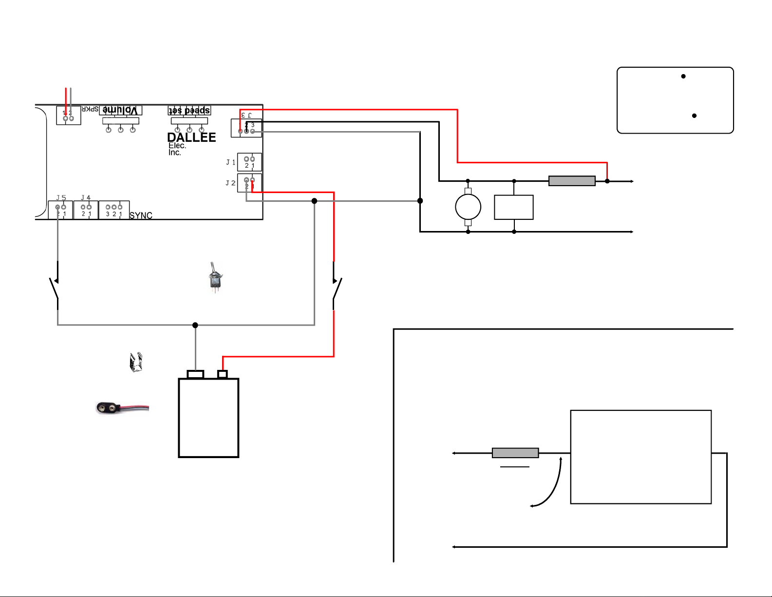
DC track power installation using standard batteries & DALLEE controller #755
speaker
Gray
Optional main
sounds switch
ON / OFF
(shown sound "ON")
Battery Holders
#579 - single 9 volt (shown)
#652 - holds 6 AA
#654 - holds 2 AA
#578 - 9 volt battery snap
connector
Battery power - must not exceed 24 volts DC.
Use one 9 volt battery or a string of 6 AA or
AAA batteries (24 volt DC maximum input). Life
depends on volume setting and speaker
impedance. Typical operation of most sound
systems for one good 9 volt batteries is about 8
hours, AA or larger is well beyond 50 hours!
– +
9V or 6-AA,
or 6-AAA
batteries
Red
Black
White
Red
+
Gray
–
524 SPST switch.
Switch shown in the OFF
position. Drawn as a spst.
ON / OFF
switch
wires with a " " ARE a
connection!
wires crossing over
(without a " ")
DO NOT CONNECT!
Right Rail
pickup
either rail may be used. Right / Left
only used for reference.
DC
motor
lighting
CHOKE *
circuits
Left Rail
pickup
*Larger motors require a larger capacity choke.
Chokes:
Item 702 - 1.5 ampere loads
Item 703 - 5.0 ampere loads
Lighted car / other engines used in consist preperation. You will know if this is necessary
by placing the locomotive / lighted cars on the track and then attempting to blow the
HORN or operate the BELL. If they do not operate with the other items on the track
then you need to do the following. We suggest doing this to all lighted cars or
engines used in the same consist since it lets the signal stay at it's maximum level.
for additional chokes order:
Item 702 for up to 1.5 ampere load
Item 703 for up to 5.0 ampere load
Right Rail
pickup
either rail may be
used. Right / Left
only used for
reference.
CHOKE PACK
looks like coil of wire with a
Formerly right
rail pickup
CHOKE
lead on each end
LOAD
Lighting load, other locomotive in
consist, or other type circuitry
drawing off of track power. As
shown one lead needs to be
disconnected from the rail and a
"CHOKE" needs to be placed in
series with the load. In most cases
the 1.5 ampere (#702) will handle
the load.
Left Rail
Pickup
3
Page 4
speaker
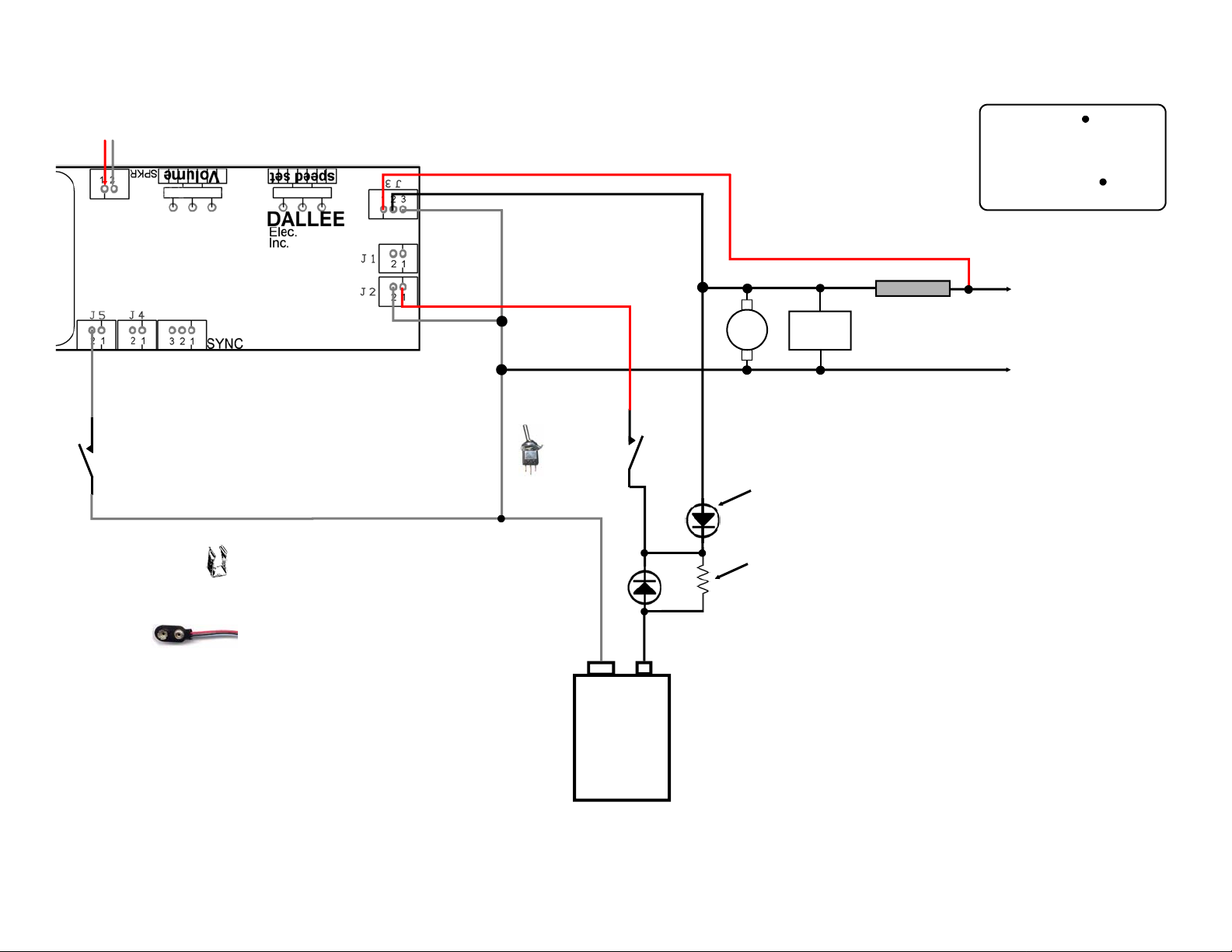
DC track power installation #2 with DALLEE controller #755.
With rechargeable or standard battery.
When track voltage exceeds battery voltage, the sound system will
operate from track voltage instead of battery voltage.
Red
Black
White
wires with a " " ARE a
connection!
wires crossing over
(without a " ")
DO NOT CONNECT!
Red
+
Gray
–
Gray
Optional main
sounds switch
ON / OFF
(shown sound "ON")
Battery Holders
#579 - single 9 volt (shown)
#652 - holds 6 AA
#654 - holds 2 AA
#578 - 9 volt battery snap
connector
Battery power - must not exceed 24 volts DC.
Use one 9 volt battery or a string of 6 AA or
AAA batteries (24 volt DC maximum input). Life
depends on volume setting and speaker
impedance. Typical operation of most sound
systems for one good 9 volt batteries is about 8
hours, AA or larger is well beyond 50 hours!
524 SPST switch.
Switch shown in the OFF
position. Drawn as a spst.
This diagram allows for the use of rechargeable batteries. When
track voltage exceeds battery voltage, the sound system will operate
from track voltage and the battery will start to charge (when in the
forward direction). If you need to charge the battery fully without the
sound system on, place the locomotive on the track (with the motor
not powered if present) and leave full track voltage on for 14 hours.
The batteries will charge whenever the locomotive track power is
set for the forward condition regardless of the sound system being
on or off. They will not charge when the polarity on the track is set
in reverse. When running in reverse, the sound system will only
operate from the battery. A bridge rectifier could be used instead of
a single diode alleviating this potential problem.
ON / OFF
switch
– +
9V or 6-AA,
or 6-AAA
batteries
Right Rail
pickup
either rail may be used. Right / Left
only used for reference.
DC
motor
lighting
CHOKE *
circuits
Left Rail
pickup
*Larger motors require a larger capacity choke.
Chokes:
Item 702 - 1.5 ampere loads
Item 703 - 5.0 ampere loads
1N4002 or
equivalent diode
(item #374)
If using a standard battery instead of
rechargeable, do not connect/use a resistor!
Resistor needs to be calculated for battery type (you must know
the charge currents of the batteries used) and maximum track
voltage used.
R = (Vtrk max - Vbatt nominal) / battery charge current
For 12 - 14 volt maximum track voltage:
1 - Item #647 (8.4v / 150mahr) rechargeable battery use 380 ohms
(1/4 watt).
6 - Item #648 (1.2v / 700mahr) rechargeable batteries in series, use
100 ohms (1/2 watt).
For 18 volt maximum track voltage:
1 - Item #647 (8.4v / 150mahr) rechargeable battery use 560 ohms
(1/4 watt).
6 - Item #648 (1.2v / 700mahr) rechargeable batteries in series, use
180 ohms (1 watt).
4
Page 5

speaker
Stationary DC power installation using track power for notch setting.
You can also add an auxillary Amplifier, see pages 8, 9, and 10.
Switch key:
S1 - Horn (momentary)
S2 - Bell
S3 - Force Cooling Fans
S4 - Main sounds off
Gray
Red
S4
S3
524 SPST switch.
Switch shown in the OFF position.
Drawn as a spst.
Gray
S2
Red
S1
speaker
Switch key:
S1 - Horn (momentary)
S2 - Bell
S3 - Force Cooling Fans
S4 - Main sounds off
Gray
Red
Gray
Red
#618 SPST momentary
push button switch.
Switch shown in the OFF posi tion.
Black
White
+
–
Red
Gray
ON / OFF
switch
Right Rail
Left Rail
either rail may be used. Right / Left
only used for reference.
524 SPST switch.
Switch shown in the OFF
position. Drawn as a spst.
+
–
fixed DC power - must not exceed 24
volts DC. If you have a HUM or
other static noise in the audio output
it is because this power is not
filtered enough. Add a large
electrolytic capacitor (470 mfd @ 25
vDC or larger) across this DC
supplies output (when power is off).
Make sure you observe the polarity
markings of the capacitor !
Stationary AC power installation using track power for notch setting.
You can also add an auxillary Amplifier, see pages 8, 9, and 10.
Black
White
Gray
+
–
Red
Gray
Right Rail
Left Rail
Red
+
extra filter
capacitor observe
polarity !
either rail may be used. Right / Left
only used for reference.
ON / OFF
switch
524 SPST switch.
Switch shown in the OFF position.
Drawn as a spst.
fixed AC power 10 - 18 vAC you MUST
NOT EXCEED 18 volts AC. DC voltage
created from AC is 1.414 X vAC, 18vAC
= 25 vDC !
A HUM in the audio output is because
the DC power is not filtered enough. Add
a large electrolytic capacitor (470 mfd @
25 vDC or larger) across the DC output
as shown (when power is off). Make
sure you observe the polarity markings
of the capacitor !
S4
S3
S2
S1
5
Page 6

DCC receiver installation using motor power for Main Sound activation and
speaker
function control for HORN, BELL, Manual Cooling Fans, Main Sounds ON / OFF
Gray
Red
Gray
S4
S3
S2
Connect S1 thru S4 to function control desired.
You do not need to connect functions you do
not intend on using.
Function key:
Red
S1 - Horn (momentary)
S2 - Bell
S1
S3 - Force Cooling Fans
S4 - Main sounds off
Black
White
Red
Gray
No connection is
required to J2. All of
the sound system
power is supplied
from the track via J1.
DCC
track power input
Connect motor
M
if present
receiver motor leads (Orange / Gray is
standard practice). If you are using a
seperate receiver merely connect the
motor leads to pins 2 (black) and 3
(white) of J3. The sound system presents
a load of 480 to 980 ohms (depends on
speed set control setting).
Make sure that your receiver is operating in
the same step mode as the transmitter !!
S1 - HORN function. Connect to desired
function output of module. Activate low to
play HORN.
Some DCC systems offer a momentary
type function. It is best to use what the
system you are using suggests.
Digitrax - use F2 function
Wangro - use F3 function
S2 - BELL function. Connect to
function output of module.
Activate low to play BELL.
Suggest function as set by DCC
system you are using.
Digitrax - use F1 function
Wangro - use F2 function
S2 -> S4 - function. Connect to extra
function, if desired. When using an extra
receiver you can use either Forward or
Reverse lamp function output of module.
Normally not activated = "high".
Activated = "low" (function ON).
ATTENTION
ALL FUNCTION CONNECTIONS are for OPEN COLLECTOR type FUNCTIONS such as those found on DIGITRAX, LENZ, NCE, and WANGRO receivers. Although there should not be any
problem with any other type, we have not verified it. The sound unit has been designed and operated with WANGRO, DIGITRAX, and LENZ systems to verify DCC operation and compatability.
ADDITIONAL NOTES:
If you feel that you need longer running time when an intermittent track power input occurs simply attach a larger filter capacitor across the DC power leads (J2). Observe proper polarity. The
plus connects to pin 1 (red), minus to pin 2 (gray) - the polarity is very important since some capacitors when connected in reverse can actually blow up like a fire cracker! The larger the
capacitor the longer operating time without track power. A capacitor of 470 mfd @ 25vDC should be sufficient, too large of a value will require a very large surge current when track power is
applied. Some transmitters cannot take the large surge current on startup and will show an overload condition when powering up.
6
Page 7

Other receiver or controller installation using motor power for Main Sound activation and
function control for HORN, BELL, Force Cooling Fans, Main Sounds ON / OFF
speaker
receiver motor leads. Connect
Black
White
Connect motor
M
if present
the motor leads to pins 2
(black) and 3 (white) of J3.
The sound system presents
a load of 480 to 980 ohms
(depends on speed set
control setting).
Function key:
S4
Gray
Red
S3
S2
Gray
Red
S1 - Horn (momentary)
S2 - Bell
S1
S3 - Force Cooling Fans
S4 - Main sounds off
S1 - HORN function. Connect to desired
function output of receiver or
activated switch. Activate low to
play HORN. This needs to be a
momentary operation.
Red
+
Gray
–
Connect S1 thru S4 to function control desired.
You do not need to connect functions you do
not intend on using.
S2 - BELL function. Connect to
function output of
receiver or activated
switch. Activate low to
play BELL.
DC battery power input.
Input voltage of 7 to 24 volts DC. Absoulute maximum
input is 35 volts DC! If the battery supply is not the
same as the receiver supply, connect the gray "-"
wire to the "-" of the receiver supply.
S2 -> S4 - function. Connect to receiver
function or switch, if desired.
Normally not activated = "high".
Activated = "low" (function/switch ON).
If you are using a receiver that
operates higher than 24 volts, it is
necessary to add a 470 ohm, 1/2
watt, resistor in series with one of
the inputs to J3 from the motor lead.
using SIGNAL TRANSISTORS for remote control of the HORN, BELL, and other functions.
C
B
Q1
E
C
B
Q2
E
to Horn input of
sound board
to Bell input of
sound board
These parts can be obtained directly from us but they do
not appear on the price schedule - call or write for prices.
This is possible when both the receiver and sound system are operating
from a common supply. The common supply can be either fixed track
voltage or fixed battery voltage. Since both the sound system and the
receiver are operating on the same supply, the common "—" power
would be the same. This circuit relies on the receiver having a logical
"HI" voltage when the remote functions are activated. Keithco and other
users requiring an inverted signal can use this optional interface circuit.
If you have another function available you could operate another function
such as a forced cooling fans. Connect another transistor as the Horn
and Bell transistors but connect the collector of the transistor to the S3
function input.
HORN function
of receiver
R1
BELL function of
receiver
R2
R1, R2 - 1.0k 1/4 watt (Brown, Black, Red)
Q1, Q2 - 2N4401 or equivalent NPN transistor
2N4401
(front view)
EBC
COMMON of receiver
("-"supply) or J2 pin2 (gray).
These are the same since
both operate from the same
supply.
7
Page 8

Other receiver or controller installation using motor power for Main Sound activation and
switches for HORN, BELL, Force Cooling Fans, Main Sounds ON / OFF
speaker
receiver motor leads. Connect
Black
White
Connect motor
M
if present
the motor leads to pins 2
(black) and 3 (white) of J3.
The sound system presents
a load of 480 to 980 ohms
(depends on speed set
control setting).
Gray
S4
Red
S3
524 SPST switch.
Switch shown in the OFF position.
Red
Gray
S1
S2
Drawn as a spst.
Switch key:
S1 - Horn (momentary)
S2 - Bell
S3 - Force Cooling Fans
S4 - Main sounds off
#618 SPST momentary
push button switch.
Switch shown in the OFF position.
+
–
Red
Gray
DC battery power input.
Input voltage of 7 to 24 volts DC. Absoulute maximum
input is 35 volts DC! If the battery supply is not the
same as the receiver supply, connect the gray "-"
wire to the "-" of the receiver supply.
Auxillary Amplifier connections
"Audio input" Connect to gray wire from sound system speaker output. Do not use the
red speaker wire from the sound system. This wire does not get connected! Either cut or
tape the red wire securely so that it cannot short to something. Never connect either of
the speaker output wires to ground. This will damage the sound system's amplifier and is
not covered under any warranty.
If desired, a speaker can still be connected to the main sound sytem speaker output as
well as another speaker from the amplifier.
auxillary AUDIO AMPLIFIER,
Item #671 or #672
If you are using a receiver that
operates higher than 24 volts, it is
necessary to add a 470 ohm, 1/2
watt, resistor in series with one of
the inputs to J3 from the motor lead.
Amplifier DC input power
Red -> +DC
Black -> ground
This needs to be the same
as the sound system power.
8
Gray
"Audio Input"
1
2
3
Page 9

speaker output
Gray
Using dual sound systems with an auxillary amplifier.
1k, 1/4w
(brn,blk,red)
Switch key:
S1 - Horn (momentary)
S2 - Bell
S3 - Force Cooling Fans
S4 - Main sounds off
Gray
S4
S3
524 SPST switch.
Switch shown in the OFF position.
Drawn as a spst.
Gray
S2
Red
S1
Connect only the switches desired for each sound
#618 SPST momentary
Switch shown in the OFF position.
system. It is best to use one with the prime mover
turned off (S4), using it to produce the Horn and Bell.
The other unit would then produce the prime mover
with only S3, to force N8, utilized. As shown.
speaker output
Gray
Switch key:
S1 - Horn (momentary)
S2 - Bell
S3 - Force Cooling Fans
S4 - Main sounds off
This unit would produce the prime mover sounds.
Gray
Red
S4
S3
524 SPST switch.
Switch shown in the OFF position. Drawn as a spst.
Utilizing S3, force N8, and S4, main sounds off,
as optional connections. The horn and bell
would not be used in this unit since the upper
unit would be producing those sounds.
S1
S2
Horn and Bell
sounds would be
produced by this
sound unit.
push button switch.
Prime mover
sounds would be
produced by this
sound unit.
Black
White
+
–
Black
White
+
–
Red
Gray
Red
Gray
ON / OFF
switch
524 SPST switch.
Switch shown in the OFF position.
Drawn as a spst.
1k, 1/4w
(brn,blk,red)
Black
Audio input. Connect as shown to
resistors and gray speaker wire from
sound system. Do not use the red
speaker wire from the sound system.
This wire does not get connected!
9
track power, receiver motor
Connect motor
M
if present
Red
Gray
Auxillary 11 or 22 watt Audio Amplifier
Red
Black
Gray
More than one power amplifier can be used. To do so
connect the input wires (gray) in parrallel from the
amplifier to the sound systems gray speaker wire or
use one amplifier for each sound system.
DC battery power input.
+
Input voltage of 12 to 24 volts DC.
–
If this is a DCC system, one of the sound
with Treble and Bass controls.
Item 671 - 11watt, 672 - 22 watt.
1
2
3
leads, or whatever you are
using to adjust the prime
mover notches.
Connect to the same power that is
powering the sound system.
units needs to have J1 connected to
the track power and no battery power
or an on/off switch would be
connected. Switch inputs s1 - s4 would
be functions.
8 ohm
speaker
use
Page 10

using dual systems with LocoMatic™ Controller
To strap off the Horn and Bell in an electric unit, connect the
SYNC white wire to the black wire. This will allow only the
prime mover sounds to operate. Cut the white wire off or
remove from the connector.
Refer to page 9 for using two sound units. The top sound unit would be
connected as shown on page 9 without switches S1 and S2. The lower
sound unit, producing the prime mover sounds, would be connected as
shown to the left with nothing connected to J4 or J5.
Track power inputs, as shown on page 3 and 4, will be the same except they
will go to both sound systems J3 connectors.
Battery connections will go to both units DC power input connector, J2.
If you do not care to use an amplifier, you must use two seperate speakers. In
that case, each sound system will have their own speaker. The speaker
connected to the lower sound unit would then produce the prime mover
sounds with air and brake release sounds, and the other speaker, connected
to the upper sound unit, will produce the Horn and Bell sounds.
For extra 2 and 3 pin ultra-miniature connectors, see item's 757 and 758.
They are listed under Accessory Items / Connectors.
adding manual control to the IN LOCOMOTIVE DC SOUND system as a
stationary unit to adjust diesel notches, steam chuff rate, or operate
brake release and cooling fans in electric's.
Connect input power, speaker, and all other connections as shown in stationary or other types of
installations except no input connections should be applied to the DC motor/track input
header (J3) pins 2, or 3. Instead, connections should be done as shown below. All other
input power, speaker, switch connections should be done as before.
Basic setup for both types of operation: Set NOTCH CONTROL (speed set) full CCW. The
potentiometer, transistor, and a knob can be obtained directly from us as item#602 but they
may not appear on the price schedule - call or write for prices.
no connection
Black
White
Red
+
Gray
–
Don't forget to connect either J2 or
J1 to the appropriate power supply.
C
B
E
2N4401 (NPN) or equiv.
External RPM control
potentiometer with knob &
transistor (item #602)
CW
50K
E B C
adding remote volume control when using an Aux illary Amplifier
With single sound systems, connect the gray wire from the speaker output to input "I". Connect
the rest as shown.
If using two sound system as shown on page 9, connect the junction of the two sound systems
to the capacitor as shown on page 9, then merely add the potentiometer as shown. This will only
work properly if the amplifier has an industry standard auxillary input.
I
audio input from
sound system
1 2 3
viewed from front
External Volume control
with knob and capacitor
(item #601)
Remote
volume
control
+
1
3
1 mfd capacitor
Observe polarity!
—›
clockwise
2
Amplifier DC input power
Red -> +DC
Black -> ground
This needs to be the same
as the sound system power.
auxillary AUDIO AMPLIFIER,
Item #671 or #672
Gray
1
2
3
using an Auxillary Amplifier with matching transformer input
10
speaker output
matching transformer
8 - 16
ohms
amplifier input impedance
Amplifier
Input
matching transformers
can be found in many
audio shops. They are
used for power amplifiers
found in car systems.
Page 11

Sample Speaker Installations
For open body shells it is necessary to make a speaker baffle instead of using
the body for a baffle. In both cases, the backside of the speaker is closed off.
Mounting a speaker facing out from
inside of the body. You have to seal
all edges of the speaker for a proper
baffle.
Body shell before speaker installation.
Using the fuel tank as a speaker
baffle is quite easy. In this case the
speaker eminates sound into the
body.
Mounting speaker in hood of engine using a metal grill for the exhaust.
Body shell after speaker installation. Speakers are mounted on a card stock formed
shelf and then hot melted in place. Air space is required between the front of the
speakers and the body bottom but the back of the speaker enclosure is completely
sealed to make a good enclosure / baffle! This type of installation yields more sou nd
per watt than one single speaker.
In the case of a long body, such as the GG1, you can place four speakers inside the
shell. As shown above, the body shell is used as the backside of the baffle The more
speakers, the better the sound (especially when using small speakers as in model
locomotives. Four speakers make an ideal configuration.
11
Page 12

alternative lighting
you might also want to consider installing our Adjustable Regulated Lighting board. The RL-ADJ (item 379) comes with four 2.7v lamps (item 383) but is capable of driving eight lamps, as shown. You can
set the intensity desired (1.25 - 6.2 volts). It maintains constant voltage to the lamps and requires nothing more for our standard DC sound systems or LocoMatic™ compatibility. Simply install the lamps
where desired, connect the input power, and peel the tape to secure. The unit can be broken into smaller strip lengths where needed. All the way down to 2" for the power module. Install in cabooses,
passenger cars, or buildings. Measures only 1/2" wide. Extra, low voltage lamps, are available. We also offer 1.5 volt lamps in various colors. See our Catalog or Web site for more details.
Like the RL-ADJ (item 379), the VRS (item 378) offers the same adjustments in a super small size. It is capable of driving 1/2 ampere of current, like the 37 9. This amounts to eight 2.7v lamps (item 383),
as shown above or our small 1.5 volt lamps as well (see our catalog or w eb site for details on other lamps). You can set the intensity desired (1.25 - 6.2 volts). It maintains constant voltage to the lamps
and requires nothing more for our standard DC sound systems or LocoMatic™ compatibility. Simply install the lamps where desired, connect the input power, and secure the board. There are also no
connections on the back side of this board so it can be mounted flush to any area. Install in cabooses, passenger cars, or buildings. Measures only 1.25" w x 1" l x 0.35" h.
Output can be adjusted from 1.25 to 6.2 volts. Input can be up to 30 volts DC,
DCC, or AC. Powers 30 of our 1.2mm colored 1.5v lamps (Red #384, Yellow
#385, Green #386), 12 #382 lamps, 8 #383 or #756 lamps.
With two diodes and light bulbs, you can also use this module to achieve
directional lighting. The drawing for this is on our web site as well.
12
1.25"w x 1"l x 0.35"h
 Loading...