

Page 1

LocoMatic™ type3 ELECTRIC Sound & Control
for AC or DC track power by
Instructions rev 1.2
CAUTION:
this device can be damaged by static discharge.
please exercise care during installation to avoid this
possibility. discharge yourself to an electrical ground
(outlet cover screw) before removing this device from
its anti-static bag. please read instruction sheet
completely before attempting to install and operate
this product.
AC or DC TRACK POWERED SOUND & CONTROL
SYSTEM - ELECTRIC LOCOMOTIVES
OVERVIEW:
have not previously been available in the model train industry.
DC operators should operate in LocoMatic™ COMMAND
CONTROL only. If operated with variable DC track power in
standard mode, then normal AC like sequencing will occur with
either a Horn or Bell constantly operating (unless switch 3 is set
on for calf mode). Conventional AC operation follows the usual
sequence of forward - neutral - reverse - neutral - forward
sequence pattern except that the initial state is switch selectable
for either start in forward or start in neutral. A locomotive can
also be switch locked in the forward position to accomodate
operation under automated situations. An additional direction
switch is provided so that if several locomotives are run in a
multiple unit lash-up simply set this switch on each locomotive to
specify which direction is forward. Recordings of actual diesel
locomotives, were digitized, to be reproduced by the
microprocessor sound system so that the sounds you hear will
be as prototypically correct as possible. Sounds produced
include user controlled horn and bell, periodic air system release,
brake release and diesel prime mover sound automatically
adjusted to speed and load conditions. The prime mover sound
can also be user forced to its full throttle position. This sound /
control system also incorporates provisions for directional head
and back up lights, also marker lights as well as other lighting,
including roof top strobes. Most lighting can also be manually
controlled by means of the LocoMatic™ controller. The
LocoMatic™ controller is also used to activate optional electric
coil couplers (requires additional item 501 and coil couplers) for
remote uncoupling of the locomotive from its train.
This sound / control system can be operated by all known classic
and modern power transformers that output low voltage 6-18
vAC or up to 25vDC to the track and will also operate with Lionel
Trainmaster in conventional mode. See appended instructions
regarding the operation of this sound / control system in
LocoMatic™ command mode simultaneously with Lionel
Trainmaster Command Control.
Additionally the sound / control system will operate with the
LocoMatic™ controller either in conjunction with your
transformer or independently with a fixed voltage supplied
through the LocoMatic™ controller to the track.
If all you want are sounds, merely connect the speaker and track
power inputs. As long as the internal e-unit remains in sync with
the LocoMatic™ sound/control systems e-unit the sounds will be
produced in sync with the locomotive.
This sound / control system includes features that
INSTALLATION INSTRUCTIONS:
consists of a main printed circuit board with an additional small
circuit board attached by a wire harness. Also included are two 5
volt light bulbs (item #756), one 0.1 mfd capacitor, two 2 pin, and
a 9 pin connector.
Refer to pages 6 and 7 to familiarize yourself with the connectors
and controls on the sound / control board. Before proceeding
with the installation, read the balance of the instructions carefully
so you will be completely familiar with what is required and what
sounds you should hear.
The main circuit board measures 1.25"w x 4.5"l x 0.8"h and
should be mounted where space permits using the double sided
tape attached to the circuit board. The small circuit board (13/16"
x 39/64"), called the sw/vol board, contains the volume control
and 6 switches. It should be mounted so that the controls are
accessible either through the frame or via a hatch or a hole in the
body shell. Double sided tape is supplied to mount this board.
Other double sided tape or small screws may also be used to
mount the sw/vol board. Be certain that the components on the
circuit boards or traces do not come in contact with any metal
objects as such contact can destroy the sound / control system.
LIGHTING INSTALLATION:
middle of the main circuit board. This connector supplies an
output of 5 volts for lighting applications as follows:
1 ....... Red .......... +5 volts
2 ...... Orange ..... +5 volts
3 ...... White ....... Lmp F ....... automatic / manually* controlled
headlight
4 ....... Blue ......... Lmp R ....... automatic / manually* controlled
back up light
5 ...... Yellow ...... Mkr F ........ automatic / manually* controlled
forward marker lights
6 ....... Brown ...... Mkr R ........ automatic / manually* controlled
rear marker lights
7 ...... Violet ....... Aux 1 ........ manually* controlled as desired
8 ....... Gray ........ Aux 2 ........ manually* controlled as desired.
Aux 1 & 2 can be number boards, ditch
lights or other lighting depending on
equipment on specific locomotives.
9 ....... Green ....... Cab 2 ........ primary use is for rooftop strobe
or mars lighting.
*requires LocoMatic™ Controller.
SPEAKER INSTALLATION:
mounted as per available space bearing in mind that sound
reproduction is enhanced when a speaker is properly enclosed
and baffled. The speaker is to connect to a 2 pin connector
located near the center edge of the main circuit board.
The speaker generally should be mounted so that the sound can
actually "get out" of the locomotive. A hole in the floor or fuel tank
is acceptable but open grills or a doorway may be a better choice
as the sound can exit upward rather than down toward the track.
In some cases, particularly with plastic body shells, just mounting
the speaker against the shell, preferably with a few openenings
1
This sound / control system
The 9-pin connector is located in the
The 8 ohm speaker should be
Page 2

at the front of the speaker, will be adequate as the vibrations of
the shell can enhance the sound. Enclosing the speaker in a
chamber will also enhance sound reproduction. A very simple
enclosure can be made with a tube. It is usually best to seal the
end of the tube, so there are no air passages to the rear of the
speaker, thus creating a sound chamber. By carefully sealing all
openings it may be possible to use the entire body shell as a
sound chamber. A simple wall behind the speaker may be all that
is possible or perhaps all that is needed.
Speakers can be attached with double sided tape, glue or "hot
melt". Enclosures can be made with plastic, wood, card stock or
even metal. Film cans or medicine bottles make excellent sound
chamber enclosures for small diameter speakers. Attachment
with "hot melt" is advantageous as the "hot melt" can be used as
a gap filler when creating an enclosure.
Speaker enclosure is an art and experimentation is definitely in
order for your installation so as to gain the maximum benefit of
the superb sound quality available in this sound system. Observe
the installation example pictures for more ideas.
OPTIONAL ITEMS INSTALLATION:
One 3 pin connector,
located next to the 9 pin lighting header, is provided to operate
optional coil couplers. The mate for this is on optional item #501,
double relay board for use with coil couplers. This board can also
be wired as a power booster for any lighting or auxillary function.
A typical use would be to turn on and off a smoke unit. Wiring for
this is provided in item 501's instructions.
This sound / control system also has a 2 pin connector that can
be used to add an optional battery backup. The battery must be
an 8.4 volt high capacity rechargeable type. Our Item #647 is
specified for this unit. Once installed with the sound / control
system, the battery will be charging whenever there is track
power "on". When track power turns "off", the battery will remain
in circuit for about 30 seconds and then automatically turn "off"
(providing sufficient charge exists in the battery). Battery backup
is not generally necessary as this sound / control system has
storage capacitors that are adequate to keep the sound system
functioning during normal power "off" for direction sequencing.
In LocoMatic™ COMMAND MODE, a battery backup is definitely
not needed as full voltage track power is "on" continuously.
Under this operating mode it is suggested that no battery be
installed or that if a battery is in circuit you limit operation to not
more than a continuous 4 hours so that you do not overcharge
the battery.
SOUNDS REPRODUCED:
HORN
is user activated in several ways. It can be activated by
the whistle switch or button on transformers so equipped or
by a separate sound activation button. The horn can also be
activated by the HORN button on the LocoMatic™ controller.
The horn will play as long as the switch or button is held on.
A manual switch allows the horn and bell to be deactivated
so that, for multiple locomotive operation, only the lead
locomotive's horn and bell will sound. When operating in
LocoMatic™ command mode, only the LocoMatic™
controller will activate the horn.
BELL
is user activated by the bell control on transformers so
equipped or by a separate sound activation button wired to
do so. The BELL can also be activated by the BELL button
on the LocoMatic™ controller. The BELL sound will latch
"on" when the bell control is activated and will latch "off"
when the control is again activated. When deactivating, the
BELL will stop at the end of a ring. BELL sound can also be
requested when electric cooling fans sound has been turned
"off". Again, a manual switch allows the bell to be deactivated
for multiple locomotive operation. When operating in
LocoMatic™ command mode, only the LocoMatic™
coontroller will activate the Bell.
BRAKE RELEASE
sound is produced when the locomotive
changes from neutral to a movement direction and will
always precede locomotive movement.
COOLING FANS (ELECTRIC)
sounds range from idle slow to
full rpm when in a direction and back to stopped when
entering neutral with a small pause after the locomotive
motor power has stopped. In neutral or with no power to the
motor the sound system will produce no sounds. When a
movement direction is selected and the speed control is
advanced to put the locomotive in motion, a brake release
will sound (see above) and the cooling fans will accelerate to
full rpm. Depressing the ALT / FORWARD button on the
LocoMatic™ controller will direct the sound system to
energize or de-energize the cooling fans regardless of motor
voltage. Depressing the ALT / FORWARD button again will
release the sound system to return to the correct cooling fan
setting. This feature allows the operator to manually force
the cooling fans "ON" in a standing train. is user activated in
several ways. It can be activated by the whistle switch or
button on transformers so equipped or by a separate sound
activation button. The horn can also be activated by the
HORN button on the LocoMatic™ controller. The horn will
play as long as the switch or button is held on. A manual
switch allows the horn and bell to be deactivated so that, for
multiple locomotive operation, only the lead locomotive's
horn and bell will sound. When operating in LocoMatic™
command mode, only the LocoMatic™ controller will activate
the Horn.
LIGHTING FEATURES:
The sound / control system has outputs
at 5 volts available for head lights, back up lights, front and rear
marker lights, two auxillary lights, and a strobe or mars function
(only certain units have this selectable).
The sound / control system allows lighting that is directional so
that the forward headlight and the rear marker lights will
illuminate when the locomotive is in forward motion. When the
locomotive is in reverse motion the rear headlight and forward
marker lights can illuminate. The headlights, marker lights and
auxillary lights can also be manually operated by means of the
LocoMatic™ controller.
Two 5 volt light bulbs are included with this sound / control
system and additional 5 volt bulbs are available in (Item 756).
These are high intensity, low current, bulbs and are ideal for
headlights. For interior or other lighting locations it is suggested
that 2 bulbs be wired in series to afford a lower light level.
In most cases, marker lights have been represented by LED
devices usually wired in parallel. LED marker lights will function
best with this sound / control system if they are rewired in series
with each other and in series with a 68 ohm 1/4 watt resistor. In
2
Page 3

some cases, 1.5 volt bulbs have been used for marker lights and
/ or headlights. There are many variations of these 1.5 volt bulbs
dependent on current draw, but generally if two bulbs are wired
in series and in series with a 100 ohm 1/4 watt resistor they will
function properly with this sound / control system. See item# 382
for 1.5v lamps.
Because of size considerations a single 1.5 volt bulb may have
been used for a headlight or backup light. In this case, again
dependent on current draw of the bulb, you can generally use
about a 220 ohm 1/4 watt resistor in series with a single bulb for
satisfactory function with this sound / control system.
Each of the lighting outputs is designed for a 60 milliamp load
and should not exceed 120 milliamps or damage will occur to
the lighting output. The cumulative output should be less than the
total current capacity of the lighting regulator which is 1/2 Amp.
Should this 1/2 Amp capacity be exceeded the lamps may
become somewhat dimmed or the regulator itself may shut down.
If this situation occurs, it may be necessary to turn "off" one or
more of the lighting functions so the total current is less than the
1/2 Amp capacity.
MANUAL ADJUSTMENTS:
There are six switches and a volume
control on the small circuit board which should be mounted as
space permits and is still accessible. It is suggested that the
volume control be set at about the 10 o'clock position for
comfortable listening. High volume settings may prematurely
damage the speaker. This is especially true for EMD type prime
mover sound systems. The six switches are normally set to the
"off" position and select the following operations:
OFF ON
Switch 1 ---------- start in
forward .................... neutral
Switch 2 ---------- sequencing
normal .................. lock in start position
Switch 3 ---------- horn & bell
can sound ................. do not sound
Switch 4 ---------- forward coupler
operational .............. deactivated
Switch 5 ---------- rear coupler
operational .............. deactivated
Switch 6 ---------- forward direction is to locomotive
front .......................... rear
Switches 3 thru 6 are used primarily when two or more
locomotives are operated together. You can turn off the horn and
bell in the trailing locomotives and deactivate the couplers
between locomotives so that only the couplers at the front and
rear are operational. If any of the locomotives are actually facing
to the rear, Switch 6 on such locomotives allows operation in
concert with other locomotives facing forward. When Switch 6
changes forward to rear all directional functions such as
headlights, marker lights and couplers are switched also. If you
are not using the coupler functions, switches 5 and 6 should be
set ON to turn off the coupler sound and activation.
OPERATION USING A TRANSFORMER:
With this sound /
control system installed, your locomotive will operate in the same
manner as other locomotives when using a transformer to vary
speed. When power is applied the locomotive will come "on" in
either the forward or neutral position as you have selected.
Momentary interuptions of power will allow the locomotive to
sequence through the usual direction positions. Sequencing can
be accomplished either by a direction switch or by turning the
speed control to "off" and then back "on".
Power interuptions for direction sequencing should be momentary
only. If power remains "off" for more than a short time it is
possible that the stored energy will be used up and the sound /
control system will shut down. When power then returns the
system will come "on" in its initial start position. If you prefer to
employ a battery back up to maintain sound during more
extended power "off" situations, provisions are there to connect a
rechargable 9 volt (8.4 volt actual) battery (item 647).
If your transformer includes whistle or bell controls, or if you have
provided sound activation buttons, you will be able to sound the
horn or the bell with these controls whenever there is power to
the track. The horn will sound as long as you hold the control
"on". The bell control is a push "on", push "off".
An added feature of this sound / control system involves the way
the motor is driven. If track power is set high while in neutral and
you sequence to a direction, the locomotive will gradually
increase its speed rather than jump directly to the high speed.
This type of operation not only looks better but also results in less
strain on the entire motor / gear drive system and is less likely to
cause derailments of the locomotive or its train.
The LocoMatic™ controller contains ten operating buttons and is
usable either in conjunction with your regular transformer or as an
independent control with a fixed voltage applied to the track. The
LocoMatic™ controller is a pass through type of device which is
wired between your transformer and the track. It will not interfere
with track power passing through it when not in use (you do not
have to disconnect it for operating standard type trains). Some of
the buttons cause activation as long as they are held "on" while
others work in a push-on, push-off mode. A pause of a few
seconds is required between pushes. The lower right hand
button, labled 'ALT', is the alternate button which provides a
second function to each of the other nine buttons. When using an
alternate function it is suggested that the ALT button be held
depressed and then another button be pressed. For example;
pressing the COUPLER button will operate the trailing coupler
while pressing ALT / COUPLER will operate the leading coupler.
Not all of the buttons will have alternate functions on all
locomotives.
The ten LocoMatic™ controller buttons perform the following:
BELL .............................. turns bell "on" or "off"
ALT / BELL ..................... restores automatic directional lighting
Note: lighting is directional until a request is
made via the LocoMatic™ controller for a
manual activation. Lighting functions will then
remain manual via the LocoMatic™ controller.
Pressing ALT / BELL will allow all lighting
functions to return to directional operation at
the next direction request.
HEADLIGHT ................... turns front headlight "on" or "off"
ALT / HEADLIGHT ......... turns rear headlight "on" or "off"
MARKERS ..................... turns front marker lights "on" or "off"
ALT / MARKERS ............ turns rear marker lights "on" or "off"
AUX ............................... turns front aux lights "on" or "off"
3
Page 4

ALT / AUX ...................... turns rear aux lights "on" or "off"
COUPLER ...................... activates the locomotive's trailing
coupler
ALT / COUPLER ............ activates the locomotive's leading
coupler
HORN ............................. activates the horn
ALT / HORN ................... activates STROBE or MARS lights
FORWARD ..................... forward motion overiding sequencing
ALT / FORWARD ........... activates / stops electric cooling fan
sound
REVERSE ...................... reverse motion overiding sequencing
ALT / REVERSE ............ forces automatic electric cooling fan
sound "on" or "off"
SLOW ............................ neutral position overiding sequencing
ALT / SLOW ................... neutral position or emergency stop
ALT ................................. alternate button for second functions.
When using this button in conjunction with
another button, press and hold this button first.
Operation using the LocoMatic™ controller with your transformer:
As previously stated, a locomotive with this sound / control
system installed will operate with your transformer in the same
manner as other locomotives, but you will have the advantage of
additional features available with the LocoMatic™ controller.
The horn and bell can be activated by either your transformer
controls or by the LocoMatic™ controller. If the bell is turned "on"
by your transformer it can be turned "off" by either your
transformer or by the LocoMatic™ controller, but if the bell is
turned "on" by the LocoMatic™ controller it must also be turned
"off" by the LocoMatic™ controller.
You can manually operate any of the lighting features on your
locomotive, that you have connected to the sound / control
system, by use of the LocoMatic™ controller. Once you have
selected any manual lighting, all automatic directional operation
is overidden, however you can return to directional lighting at any
time by using the ALT / BELL button.
Mars / Strobe Lighting Effects with the LocoMatic™ Controller:
This LocoMatic™ Sound & Control System is equipped with a
Mars or Strobe lighting effect. They are selected with the
LocoMatic™ controllers Alt-Horn button.
To activate the Mars light press and release the Alt-Horn button.
If the headlight is on, then the Mars light effect will start. If the
Headlight is off the Mars light effect will start when the Headlight
comes on. When the Mars light is on and the Headlight goes off,
as in normal sequence operation, the Mars light will also go off. If
you want the Mars light to stay on, merely enter manual lighting
operation by turning on the Headlight. Since the Mars light
follows the headlight operation, A-A operation is not
compromised when selection switch 6 is placed ON. This way
only the locomotive with the Headlight on will have the Mars light
operational.
To activate the Strobe light function press and release the
Alt-Horn button twice, with a pause between presses. The first
activation starts the Mars light. The second activation starts the
Strobe light. The Strobe light operates whenever the LocoMatic™
Sound & Control System remains powered.
To turn all Mars and Strobe lighting effects off, merely press and
release the Alt-Horn button a third time.
The optional electric coil couplers are activated ONLY by the
LocoMatic™ controller. There is a brief waiting time between
coupler activations and a minimum of 8 volts on track is
necessary (unless your couplers do not function smoothly). The
couplers can be activated either in neutral or in a motion direction
as you prefer.
With the LocoMatic™ controller in place it is no longer necessary
to follow the forward - neutral - reverse - neutral - forward
sequence. If you are in NEUTRAL and wish to go forward,
depress and release the FORWARD button. The locomotive will
accellerate in the forward direction to the speed set by track
voltage. You can actually set the speed control at a fixed voltage
and operate the locomotive with just the FORWARD, REVERSE
and SLOW buttons. The sound / control system has incorporated
a momentum feature that will gradually increase speed to the the
set voltage rather than just jump to that speed. The FORWARD
button will result in a gradual increase in speed up to the preset
voltage in the forward direction. The SLOW or ALT / SLOW button
will return the locomotive to neutral. The REVERSE button will
result in a gradual increase in speed up to the preset voltage in
the reverse direction. The momentum feature will also work with
the direction control on your transformer if you prefer to employ
usual sequencing.
If there seems to be a lack of response to the buttons on the
LocoMatic™ controller it is generally due to either poor electrical
contact between the pick up rollers and wheels and the track
because of dirt, or the lack of a choke (see "supplemental note"
below) in series with something that is getting its power from the
track.
In summary, a locomotive with this unique sound / control system
installed and with the LocoMatic™ controller will function in the
same manner as other locomotives, has the added benefit of very
smooth slow speed operation with momentum acceleration and
has sequence overide so that you can select the direction of
motion as you desire.
LocoMatic™ COMMAND CONTROL
In addition to all of the previously described features this sound /
control system will operate independently with a fixed 10 to 18
volts AC, or up to 25 volts DC, passing through the LocoMatic™
controller to the track. To enter the LocoMatic™ COMMAND
MODE all power to the locomotive must be "off" and all stored
energy exhausted. Once you are sure that all power is gone, set
Switch 1 to select neutral start and set Switch 2 to lock. With the
locomotive locked to start in neutral, full LocoMatic™ COMMAND
MODE is entered as soon as track power is applied. Turn the
speed control on your transformer to output approximately 10
to18 volts and you are ready to operate in LocoMatic™
COMMAND MODE. UNDER NO CIRCUMSTANCES SHOULD
THE TRANSFORMER VOLTAGE IN THIS OPERATING MODE
EXCEED 20 VOLTS AC, 26 VOLTS DC.
With the fixed voltage on track in this operating mode all lights
when turned "on" including lighting in passenger cars or other
equipment will be at full illumination.
The horn, bell, lighting and coupler controls function as before
4
Page 5

except that the locomotive will no longer respond to the whistle
and bell controls on your transformer. Lowering the voltage on
your transformer will only effect a reduction in the top speed
possible.
The FORWARD, REVERSE and SLOW buttons are now speed
and direction controls. Press and release either FORWARD or
REVERSE and your locomotive will begin in that direction. With
each, approximately 1/2 second, momentary button activation
the speed will increase one step through a total of 24 steps.
Holding a button "on" will continuously increase through the
steps to full speed. To slow down you can activate or hold the
SLOW button through the steps to a stop. You can also slow
down by using the opposite direction button. If the locomotive is
in forward direction and you hold the REVERSE button, the
locomotive will slow to a stop and then accelerate in reverse.
Similarly, if running in reverse, holding the FORWARD button will
result in a slow to stop and then an acceleration in forward. The
ALT / SLOW button results in an emergency stop.
If there seems to be a lack of response to the buttons on the
LocoMatic™ controller it is generally due to either poor electrical
contact between the pick up rollers and wheels and the track
because of dirt, or the lack of a choke (see "supplemental note"
below) in series with something that is getting its power from the
track.
NOTE: regarding multiple unit lashups - because of the
possibility of lack of response due to poor electrical contact it is
suggested that you do not attempt control changes to multiple
units while such locomotives are on track areas of poor contact
such as switches or crossings. If a multiple unit locomotive loses
synchronization between units either increase to full speed or
come to a full stop to restore synchronization.
Operating a locomotive, with this sound / control system
installed, under LocoMatic™ COMMAND CONTROL is simply
the use of the buttons on the LocoMatic™ controller to
implement the desired motions and sounds.
****** SUPPLEMENTAL NOTE ******
The signals generated by the LocoMatic™ controller may be
adversely affected by any powered device that is connected to
the track at the same time that the LocoMatic™ controller is
functional. This would include track powered accessories, lighted
cars or a lighted or powered locomotive operating from the same
transformer that is passed through the LocoMatic™ controller.
To eliminate this possibility it is required that all accessories be
independently powered by a separate transformer or
transformers. Lighted cars or other lighted or powered
locomotives that will be operating with a locomotive with this
sound / control system installed MUST BE MODIFIED by
installation of a choke in series between track pick up and the
lights and/or motor.
The most common installation would be to locate the wires
coming from the center rail rollers (3 rail operators) or right rail (2
rail operators) and disconnect them from the present location.
Connect these wires to one end of the choke and then connect
the other end of the choke to the same location that the wires
were originally connected to. Be sure to properly insulate your
connections and to mount the choke so that it does not move.
Double sided mounting tape makes a simple and neat
installation.
In some situations for two rail operators, it may be simpler to
connect the choke between the lamp base and the proper rail
previously going to the lamp base. Either method is acceptable
as long as the choke is in series between the track and the load
and the bases of each car are not connecting to each other with
metal couplers.
APPENDIX:
simultaneous operation of a LocoMatic™
compatible locomotive with a lionel trainmaster™ command
equipped locomotive. Since both of these control systems can
function with a fixed AC voltage it becomes possible to operate
simultaneously and independently with both systems on the
same track if certain conditions are met.
The fixed voltage power to the Lionel Trainmaster Command
System must be passed through the LocoMatic™ controller
before being connected to the track. The LocoMatic™ controller
does not interfere with the Lionel Trainmaster Command Control
System. All Command equipped locomotives or other devices
that are common to the fixed voltage power supply will require
the installation of a choke in series with power pick up. This
series connection can be made either on the center rail pick up
or on the ground, whichever is easier. Refer to SUPPLEMENTAL
NOTE, for additional information.
With the above installation completed and track power "on", the
Lionel Command equipped locomotive is operational via the
Trainmaster Command Control System. Another locomotive,
equipped with a LocoMatic sound / control system in the
LocoMatic™ COMMAND MODE, can also be operated at the
same time on the same track via the LocoMatic™ controller.
Motor Problems:
If your locomotive reset's to the forward
position when operating in standard mode, or lurches
intermittently when operating in LocoMatic™ command mode,
you will need to install a choke in series with each motor lead to
eliminate large motor noise from becoming fed back to the sound
system. The chokes functions best when placed at or as near to
the motor as possible. Chokes from item 702 or 703 can be used
in most cases. There is on board filtering for this problem but it is
best handled at the motor brushes. This is also why a capacitor
is placed across the motor brushes as shown in the wiring
instructions. This only happens with motors that produce severe
spikes or generate RF when operating.
DUAL MOTORS: When connecting to a locomotive with dual
motors, the motors are normally connected in parallel from the
factory. The filter capacitor should be placed on the motor
brushes closest to the LocoMatic™board. If the locomotive has
DC can motors, try connecting the motors in series instead of
parallel. Most locomotives have an extremely high rate of speed.
By connecting the motors in series not only reduces the top end
speed of the locomotive but also results in a lower motor current
consumption with better locomotive low end performance! To
make a series connection, simply place one power lead on the
motor#1 brush, then take the other brush lead to motor#2's
brush. The other power lead then connects to the other motor#2
brush. If the motors rotate opposite of each other simply reverse
the brush leads of the motor that rotates opposite of the direction
you want the locomotive to go when in the forward state.
5
Page 6

COMMON HORN SIGNALS
SOUND
short .......................... apply brakes, stop
2-long ........................ release brakes, proceed
long, 3-short .............. flagman protect rear of train
4 or 5 long ................. recall flagman
2-short ....................... acknowledgment
3-short ....................... back up movement
4-short ....................... call for signals
short, long ................. inspect train line for leak or brakes
2-long, short .............. approaching meet or wait point
2-long, short, long ..... approaching grade crossings
continuous long ......... approaching stations or junctions
successive shorts ...... alarm for something on track
INDICATION
sticking
installation - speaker & sw/vol board
LocoMatic™
SwVol Board
Selector Switch & Volume Control Board.
Mount with tape supplied in a convenient location, or use
other double sided tape, or small screws. Be sure not
to allow any metal parts to contact any parts or traces
on the board, this will damage the system. This board
is connected to the Main Board with a 9 pin wire
harness to allow for a more convenient placement.
Rotating the "VOL" (volume) control clockwise will
increase the volume. A complete counter-clockwise
rotation will yield no sound!
Note: It is possible to destroy a standard round speaker
when operating at higher volumes. This is especially
true with EMD type sound systems. The sound system
contains a 1 watt audio amplifier and the standard
speaker is capable of sustaining 0.2 watts continuous.
The standard speaker is a high efficiency type. You can
connect two standard speakers in series to obtain
higher volumes with less damage to the speakers.
Volume control
Selector switches
Standard round speaker
when soldering wires to rear
of speaker, care must be
taken so that the wires do not
come in contact with the
speakers metal frame!
Mounting Templates for LocoMatic™ SwVol Board
Actual size mounting template to assist in mounting the switch / volume (sw/vol-h) control board.
6
Page 7
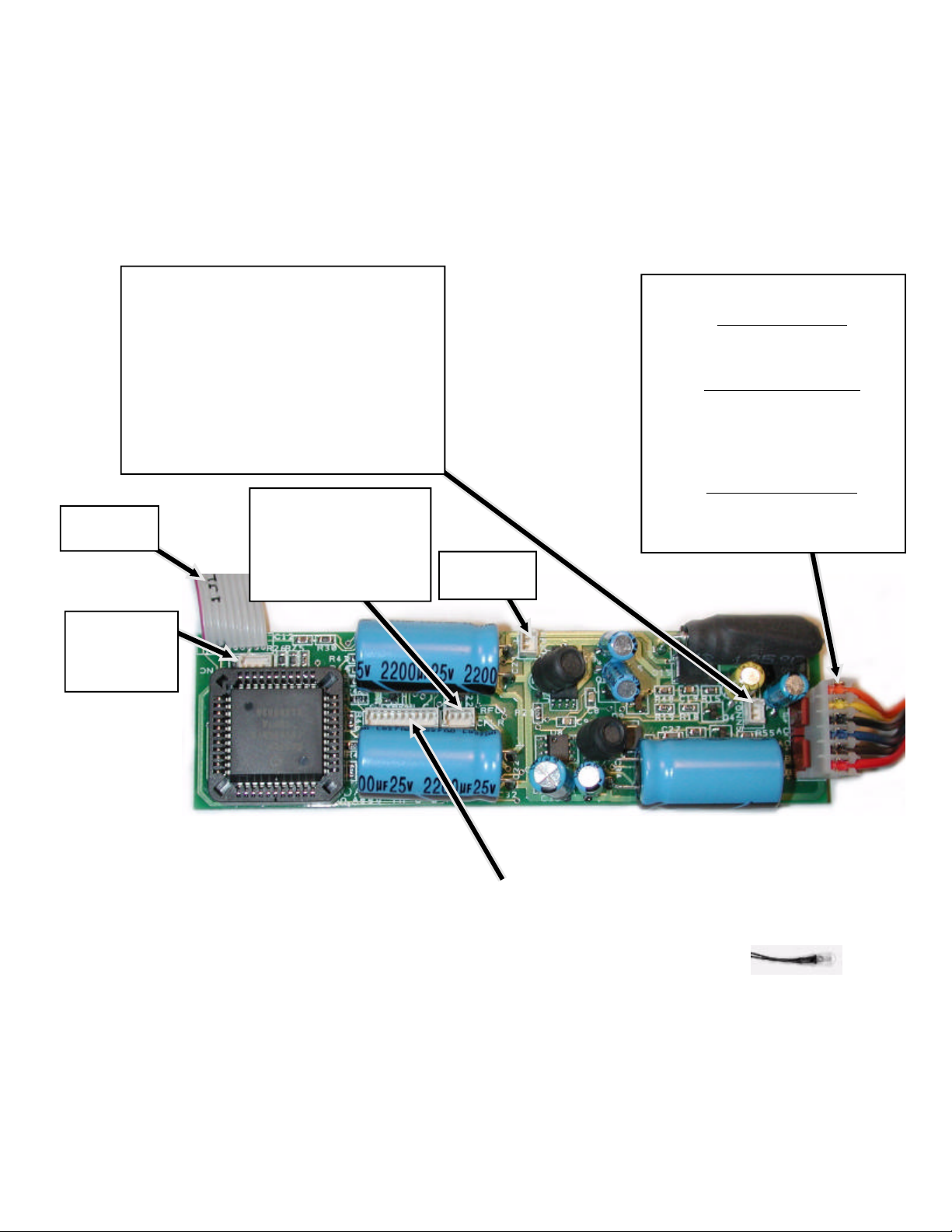
installation - connections to main board
LocoMatic™ Main Board
The main board is supplied with double sided tape
especially made to be electrically insulated, non
absorbent to moisture, anti-fungal, etc.. To mount the
board find and clean (possibly with alcohol to remove
grease) a location. Peel the tape cover off. Press to
secure in place. More tape can be obtained as item 388.
The small connectors are handled better using a tweezers
or small needle nose pliers to place the connectors
together. When seperating the connectors DO NOT pull
on the wires! Instead, slide a tweezers (or small flat
screwdriver between the top connectors lip and the board
mate. Care must be taken when handling these small
connectors.
Auxillary Backup Battery input
Use only item #647 rechargeable battery! Item
#578 contains connector snaps with wires.
Item #579 contains mounting clips or use Item
#388 double sided foam tape.
Connect the red wire to the red battery clip
wire and the gray wire to the black battery clip
wire. Insulate the connection properly. DO
NOT get these wires reversed, severe damage
to the battery / unit / and you can occur!
to Sw/vol-h
board
SYNC input
not used with
Diesel sound
systems
Coupler Outputs
1 .... Red ..... +5 volts
2 .... Black .... Front
3 .... White ... Rear
for use with item#501 only!
Main Power / Motor Connections
Motor Brushes
1 ....... Red
2 ....... Brown
Track Power Input
3 ....... Blue 3rail - center roller pu
2rail - left rail pickup
4 ....... Black 3rail - chassis pickup
2rail - right rail pickup
Motor Field Wires
5 ....... Yellow
6 ....... Orange
Speaker
connection
LocoMatic™
type 3
Main Board
Lighting Outputs:
each output shown, as described in the main text, is capable of driving
one 60 milliamp load. This load may be a light bulb, as supplied, LED's
(with limiting resistor), or a series of light bulbs. Item #756 contains more
lamps as provided. More detailed optional connections exist on the
following pages.
Connect the proper wires to supplied lamps as described. Insulate
properly. As with any connections, an improperly or uninsulated wire
touching the frame or other wire will damage the unit! Any damage as
such is not covered under warranty. When connecting the lamps to the
common +5v power, split the load between the two wires (red & orange).
Use one for the front lights and the other for the rear lights. If any
switched lamp output no longer operates, this is a sign that the output
was either overloaded or came in contact with another wire. A short
between wires to the lamp is also a overload. This would indicate a need
for repair and has to be returned. Again, this type of failure is not covered
under warranty since it is due to improper handling during installation.
Lighting Outputs
1 .... Red ....... +5 volts
2 .... Orange .. +5 volts
3 .... White ..... Lmp F
4 .... Blue ....... Lmp R
5 .... Yellow .... Mkr F
6 .... Brown .... Mkr R
7 .... Violet ..... Aux 1
8 .... Gray ...... Aux 2
9 .... Green .... Cab 2 ..... primary use is for rooftop strobe
or mars lightingif applicable.
7
.Item # 756
5 Volt, 60 milliamp
high intensity lamp.
Page 8
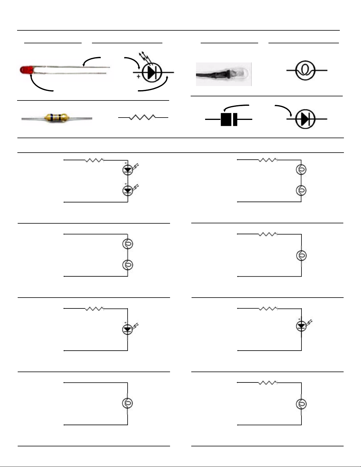
Electical parts and their symbols
Physical
shown larger than actual size
shown larger than actual size
Red or Orange Wire
Wires from:
Marker Rear or
Marker Front
Yellow or Brow Wire
Electrical symbol
anode
(light emitting diode)
LED
flat side = short lead = cathode
resistor
Wiring various Lighting Effects
68 ohm
(blue, gray, black)
Marker Indicators
( LED's )
Physical
shown larger than actual size
Red or Orange Wire
Wires from:
Marker Rear or
Marker Front
Yellow or Brow Wire
light bulb
anode
diode
100 ohm
(black, brown, brown)
Electrical symbol
Marker
Indicators
(1.5volt,
15milliamp,
lamps )
Wiring LED's as Marker Lights
Red or Orange Wire
Wires from:
Cab 1 or
Aux 1 or
Aux 2
Violet or Gray Wire
Cab Interior
#383 or #756
Wiring light bulbs in series as Interior Lights
Red or Orange Wire
100 ohm
Wires from:
Cab2 - Strobe
Green Wire
(black, brown, brown)
Strobe Lamp
Wiring an LED as a Strobe Light
Red or Orange Wire
Wires from:
lmp F
lmp R
White or Blue Wire
#756 lamps
as supplied or
order extras)
(use Item
Lamps)
( LED)
5 volt lamp
(use Item
Wiring 1.5v Light bulbs as Marker Lights
Red or Orange Wire
220 ohm
(red, red, brown)
Wires from:
Any Lighting
Output
appropriate Wire
Wiring 1.5v Light bulb for any use
Red or Orange Wire
68 ohm
(blue, gray, black)
Wires from:
Any Lighting
Output
appropriate Wire
Wiring WHITE LED instead of lamps
Red or Orange Wire
220 ohm
(red, red, brown)
Wires from:
Any Lighting
Output
appropriate Wire
Cab Interior
(1.5volt,
15milliamp,
Lamp)
White LED for
Headlight
(item#536 or
item#537)
a 68 ohm
resistor is OK
for this
application.
Cab Interior
( Lamps )
Wiring 5v Light bulb as headlight
8
Wiring 5v Light bulb for any use
Page 9

AC track power installation - Series Motor / Track connections
Main Power / Motor Connections
Place 0.1mfd capacitor
(chicklet) across
motor brushes.
Motor Brushes
1 Red
2 Brown
1
2
Track Power Input
3 ...... Blue (3 rail ........ center roller pickup)
(2 rail ....... right rail pickup)
4 ...... Black (3 rail ........ chassis pickup)
(2 rail ......... left rail pickup)
3
4
5
6
Motor Field Wires
5 ..... Yellow
6 ...... Orange
If the engine does not have a chassis (outside rail) pickup from each
truck you should add one to prevent intermittent track pickup from
occuring. Adding multiple center rail pickups will also help.
Help for Am Flyerl series motors.
the wires are normally terminated. Colors indicated are those
that match the LocoMatic™ board connector and not the
locomotives existing wires.
Field1 - connect original
red to Yellow (5)
Field2 - connect original
black to Orange (6)
This picture shows where
Brush1 - connect
original yellow
to Brown (2)
Brush2 - connect
original green
toRed (1)
Help for Lionel series motors.
early Lionel. Right is later series motor style. It is always better to add a ground wire to both outside rail pickups and the chassis. When more
than one center roller is available always connect to both, also secure the center pin from rotating with the roller.
Colors indicated are those that match the LocoMatic™ main board connector and not the locomotives existing wires.
These pictures show where the grounded field wire needs to be broken from the chassis for the motor power. Left picture is
Field - Orange
(previously connected to the
chassis pickup ground lug above)
Brush - Brown
Field - Yellow
Field - Orange
Brush - Brown
Track Input - Black
Brush - Red
NOTE: pictures do not depict the
0.1mfd capacitor across the
motor brushes as shown in
wiring diagram above. This
needs to be done!
(chassis pickup)
Track Input - Black
(chassis pickup)
Brush - Red
Track Input - Blue
(from roller pickup)
Track Input - Blue
(from roller pickup)
9
Field - Yellow
(previously connected to the
chassis pickup ground lug above)
Page 10

track power installation - DC Motor / Track connections
Main Power / Motor Connections
Place 0.1mfd capacitor
(chicklet) across
motor brushes.
Motor Brushes
1 ...... Red
2 ...... Brown
3 rail operators: If the engine does not have a
chassis (outside rail) pickup from each truck you
should add one to prevent intermittent track pickup
from occuring. Adding multiple center rail pickups will
also help.
2 rail operators: If the engine does not have a pickup
wire for each rail, you should add one. DO NOT rely
on proper pickup through the wiping action of a truck
against the chassis for a proper pickup.
Multiple motors: when more than one motor is
present you may want to wire them in series to
reduce the top end speed. This is especially true of
most 3 rail chassis since the gear ratio is higher than
neccessary. Place the capacitor shown on the motor
brushes closest to the connection of the power feeds
(red & brown) from the main board. If placing motors
in series, either place one capacitor on each motor or
connect to wire splice at closest motor to power feed.
Track Power Input
3 ...... Blue (3 rail ........ center roller pickup)
(2 rail ....... right rail pickup)
4 ...... Black (3 rail ........ chassis pickup)
(2 rail ......... left rail pickup)
connect wires together
5 ..... Yellow
6 ...... Orange
1
2
3
4
5
6
Main Power / Motor Connections using series diodes to drop motor speed
Place 0.1mfd capacitor
(chicklet) across
motor brushes.
Motor Brushes
1 ...... Red
2 ...... Brown
Track Power Input
3 ...... Blue (3 rail ........ center roller pickup)
(2 rail ....... right rail pickup)
4 ...... Black (3 rail ........ chassis pickup)
(2 rail ......... left rail pickup)
Series Diode drop
1
2
3
4
5
6
Use 6 ampere diodes (item 375) for heavy
motor loads, 1 ampere diodes (item 374)
for lighter motor loads (as in newer 'S'
gauge equipment) . One or more diodes can
be used. As shown, two diodes are used
yielding a 1.5 volt drop. This is also a drop in
voltage going to the DC motor, thus lowering
it's RPM for a given voltage. By adding more
diodes in series you can effectively reduce
the top end speed of any locomotive and
make a jack rabbit engine more tolerable
without effecting the sound system.
:
Series Diode drop
5 ..... Yellow (to anode '+' )
6 ...... Orange (to cathode '-' )
When more than one motor is in a locomotive you can either leave them in parallel, as originally wired, or place
Note:
them in series to reduce the top end speed. Remember, the power stage is rated for 3 amperes. Higher load
current will damage the electronics. In general, most newer locomotives with dual motors are only consuming 3
amperes. If in doubt you can always place a fuse in series with a motor brush wire.
10
Page 11

Although the following sample installations show diesel
locomotives all is applicable to Electric's
no lights Headlight Headlight and
Number Boards
Sample installation - Am. Flyer GP-7
Rear Marker
Lights and
Number Boards
Number Boards
and Interior
Lights
Marker Lights
When mounting in a GP-7, things get a bit tight. Shown is how to place the main board. The sw/vol board may be placed so
that the controls show through the bottom where the reversing unit lever was already punched out as shwon below. The
speaker chamber could be made towards the front of the engine, possibly utilizing the cab area by the windows.
11
Page 12
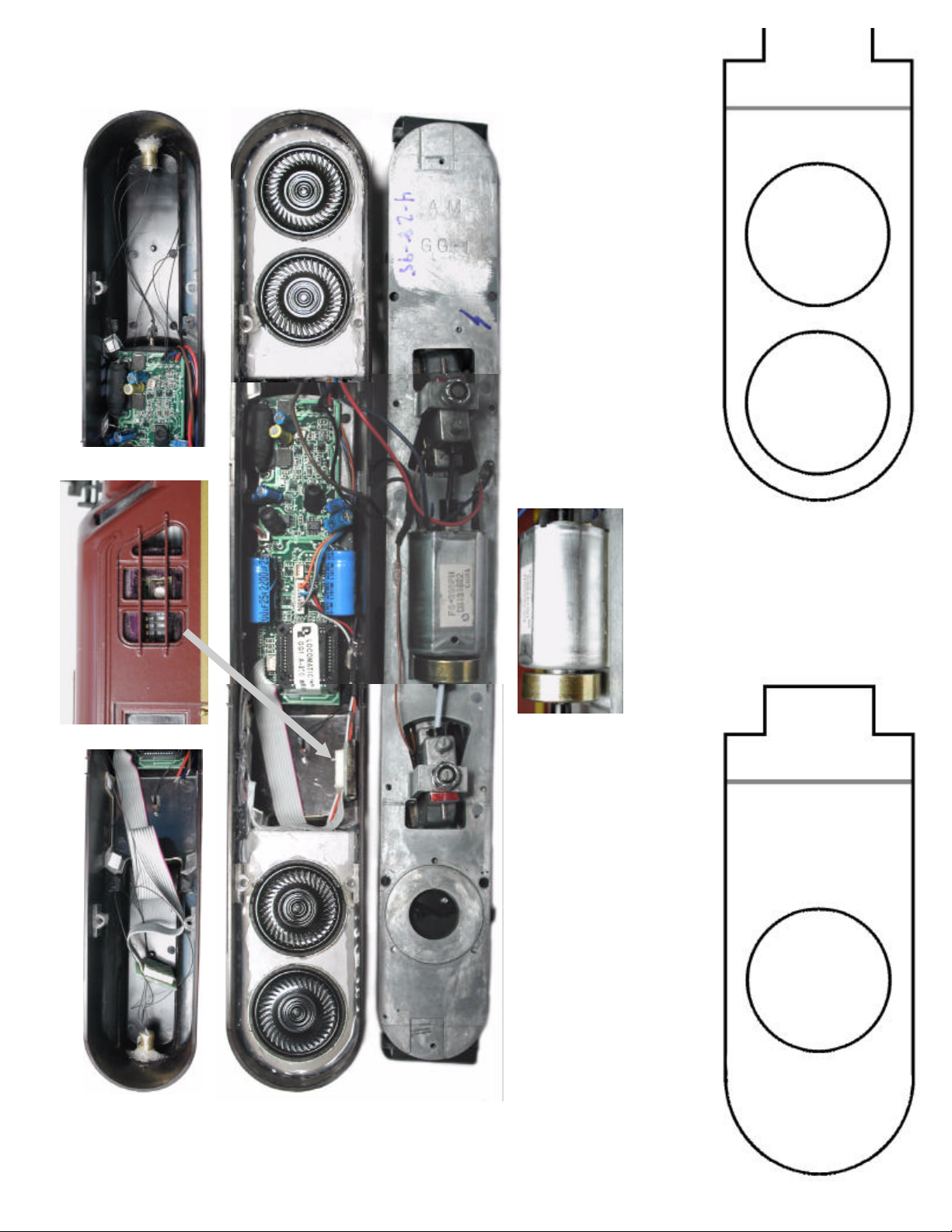
American Models GG-1 LocoMatic™ Type3 Installation
mounting template.
them and glue onto a stiff cardboard. Cut out the speaker
circles. Fold on the gray line. Mount the speakers with a glue.
Secure the entire unit inside the shell completely sealing the
Use the cutout templates below for speaker mounting. Copy
edges as shown. Hot Melt was used for the installation.
1.5" speakers (item
When installing four
1/16" thick tape.
change motor mout to
Double Speaker
the speaker insert.
#661) wire in series
parallel as shown in
wire them in series.
polarity in all cases!
Observe the speaker
For two 1.5" speakers,
12
Single Speaker
mounting template.
sided tape and mount board flush to the roof top. Also
clearance for the drive box stud (or remove the stud).
Study the pictures for wire, lamps, sw/vol, and speaker
remove the one 2200mfd capacitor, as shown, to obtain
To mount sound unit you must remove the 1/8" double
The sw/vol board was mounted with double sided tape
placement.
placed on the front side of the board and then made
Headlights were mounted using a brass tube as a shroud.
black with a marker. Carefully fold the gray flat wire to fit.
Page 13

Sample installation - Short GG-1
Place 1/16" tape on board to prevent motor / chassis from
shorting to board.
Make spacers, with slot guides to hold board, to raise
board brom bottom to clear wires.
Position board on angle to clear shell / chassis and
motors when swung to full extent (motors move to
negotiate tight curves).
Use a non-conductive glue to hold board on spacers.
"Quick Grag" works well for this. Make rear support
bracket to keep board from tipping.
Install lamps in parrallel for illumination of the markers.
Then cover the lamps with foil tape to prevent light from
seeping through.
Install speaker in enclosed tube flush to the inside ceiling.
Coil couplers could also be added but would need addition
modifications to the coupler pockets for installation and item #501.
An easy location for the sw/vol board is
near the previous lockout switch
location.
If opening the chassis for the sw/vol, do
this first before mounting the main
board.
Mill open or drill multiple holes and file
smooth to gain access to the
switches and volume control. If only
the volume control is of importance,
locate suitably about an existing hole.
Be sure that none of the tracks on
the board or switch mounts touch the
chassis. This would permanently
damage the microcontroller and is
not covered under warranty.
Place 1/16" double sided tape on front
side of board and secure in place.
An added touch would be the addition of two interior cab lamps.
These can be accessed from the LocoMatic controller as
Aux1/Aux2. Use Aux1 as the forward cab and Aux2 as the rear
cab. This way you can independently illuminate the proper
operating cab when at idle.
13
Page 14
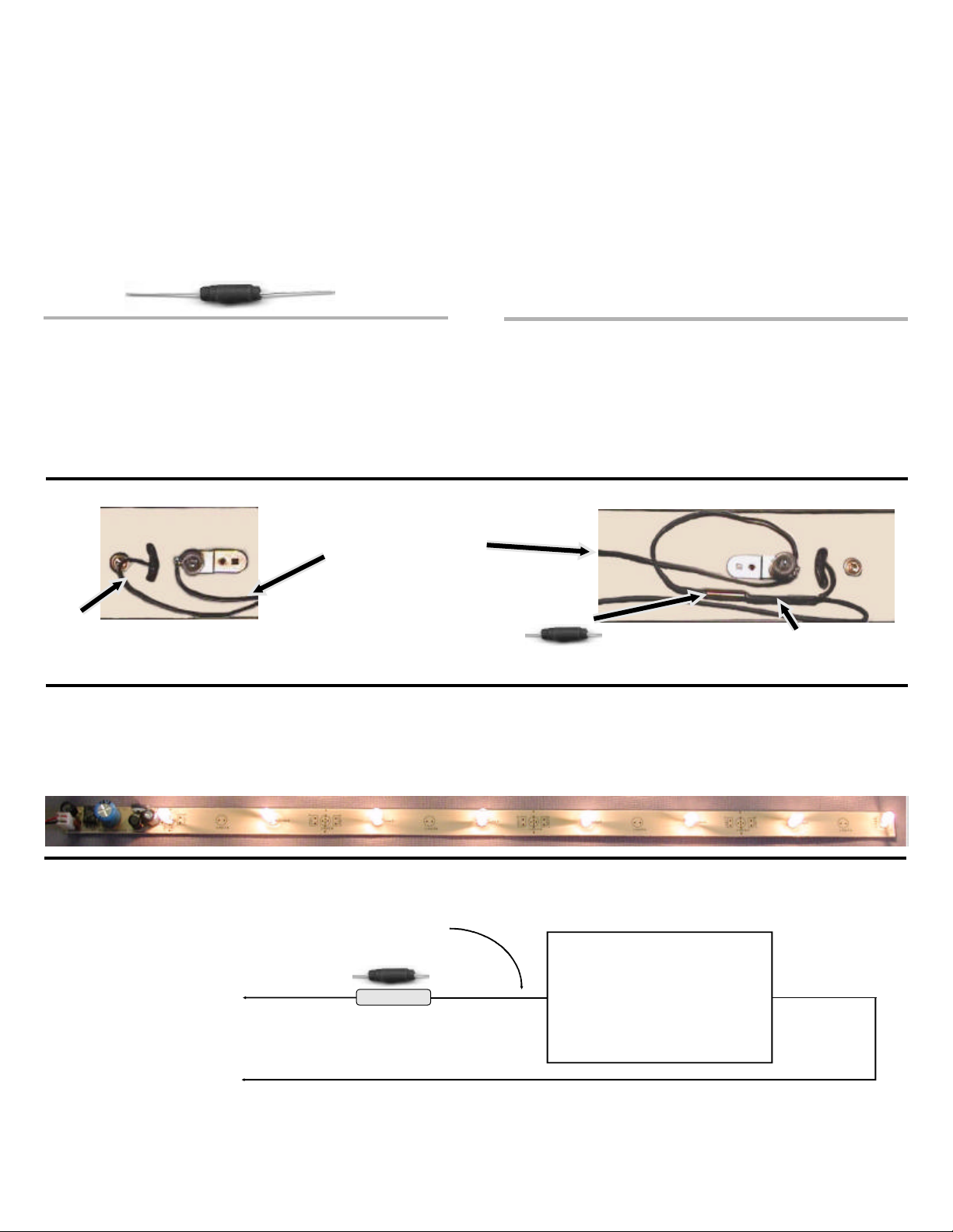
Choke installation
When using other equipment on the same track with the
LocoMatic™ system, it is neccessary to install choke's in
series with the other items drawing power. These other
items could be lighted cars or other engines running in the
consist. This is neccessary to insure proper signal
strength from the LocoMatic™ Controller. Without proper
signal strength, the locomotive could receive improper
instructions or no instructions at all when an operation is
selected from the LocoMatic™ Controller.
CHOKE (Coil)
Input
Output
To install the choke in 3-rail passenger cars with multiple
pickups:
1 ...... remove the existing center roller pickup wires.
2 ...... connect these wires together to form a common wire.
3 ...... place a new wire from one truck roller to the second truck
roller. This will give you better pickup and should be done
on all lighted cars.
4 ...... connect one end of the previous center roller pickup wire
to one end of the choke.
5 ...... connect the center roller jumper wire (the new wire
installed in step #3) to the other end of the choke.
6 ...... be sure to electrically insulate all connections.
To install the choke in other 2-rail lighted cars:
1 ...... locate right rail lamp power feed wire.
2 ...... inside the car, cut the power feed wire making two ends.
3 ...... connect one power feed end to one side of the choke and
connect the other power feed end to the other side of the
choke.
4 ...... be sure to electrically insulate all connections.
one side of passenger car
3-rail choke installation
To install the choke in 2-rail AF lighted cars:
1 ...... locate center lamp power feed wire.
2 ...... inside the car, cut the power feed wire making two ends.
3 ...... connect one power feed end to one side of the choke and
connect the other power feed end to the other side of the
choke.
4 ...... be sure to electrically insulate all connections.
other side of passenger car
lamp power
(from other end of choke - connects
to all input tabs of lamps in car)
center roller pickup
(to other center roller pickup)
choke
center roller pickup
(to other center roller pickup and one side of choke)
alternative lighting
you might also want to consider installing our Adjustable Regulated Lighting board. The RL-ADJ (item 379) comes with 4 lamps but is capable of driving
eight lamps, as shown. You can set the intensity desired (1.25 - 5 volts). It maintains constant voltage to the lamps and has it's own choke so no other
modifications are needed. Simply install the lamps where desired, connect the input power, and peel the tape to secure. The unit can be broken into smaller
strip lengths where needed. Install in cabooses, passenger cars, or buildings. Measures only 1/2" wide. Extra, low voltage lamps, are available (item 383).
basic choke installation diagram
Formerly center rail
or right rail pickup
Center Rail ..... (3 rail)
Right Rail ........ (2 rail)
pickup
Outside Rail .... (3 rail)
Left Rail .......... (2 rail)
pickup
When installing in 2 rail equipment, use all Center Rail
references as Right Rail and all Outside Rail as Left Rail.
choke
LOAD
Lighting load, other locomotive in
consist, or other type circuitry
drawing off of track power. As shown
one lead needs to be disconnected
from the rail and a CHOKE needs to
be placed in series with the load. In
most cases the 1.5 ampere (#702)
will handle the load.
for additional chokes order:
Item 702 for up to 1.5 ampere load
Item 703 for up to 5.0 ampere load
14
 Loading...