

Evaluates: MAXQ3210
MAXQ3210 Evaluation Kit
______________________________________________ Maxim Integrated Products 1
For pricing, delivery, and ordering information, please contact Maxim/Dallas Direct! at
1-888-629-4642, or visit Maxim’s website at www.maxim-ic.com.
Rev 0; 6/06
General Description
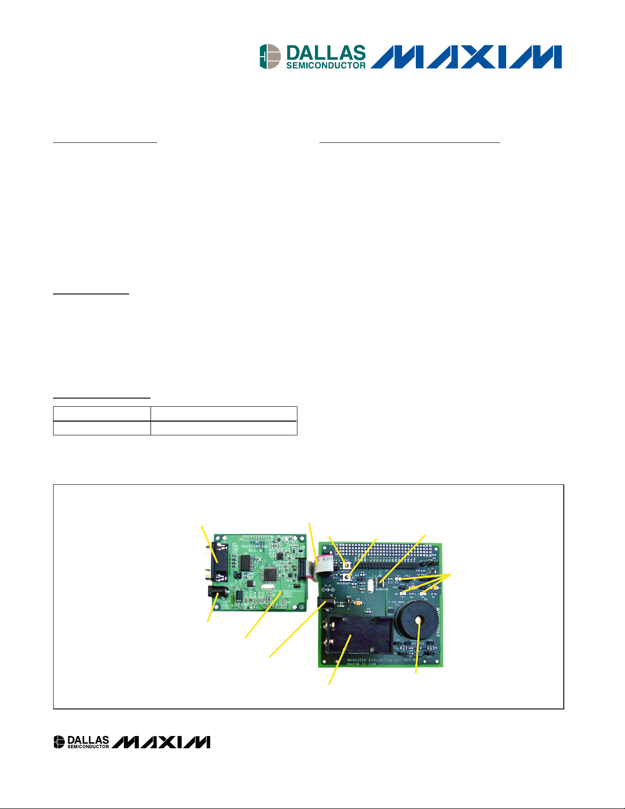
The MAXQ3210 evaluation kit (EV kit) is a proven platform to conveniently evaluate the capabilities of the
MAXQ3210 voltage regulator microcontroller. The kit
contains the MAXQ3210 with pins brought out to headers, JTAG programming interface, 9V battery clip,
piezoelectric horn, and pushbuttons and LEDs to control and display board operation. With the included
power supply, software, serial-to-JTAG interface board,
and an RS-232 cable connected to a personal computer, the kit provides a completely functional system ideal
for evaluating the capabilities of the MAXQ3210.
♦ MAXQ3210 EV Kit Board with Processor and
3.57MHz Crystal Installed
♦ Serial-to-JTAG Interface Board and JTAG Cable
♦ MAXQ3210 Evaluation Kit CD-ROM
Features
♦ Easily Loads Code Using Bootstrap Loader and
Serial-to-JTAG Interface Board
♦ JTAG Interface Provides In-Application
Debugging Features
Step-by-Step Execution Tracing
Breakpointing by Code Address, Data Memory
Address, or Register Access
Data Memory View and Edit
♦ 9V Battery Clip for Use with MAXQ3210 Voltage
Regulator
♦ Piezoelectric Horn with Optional Volume
Adjustment Jumpers
♦ Evaluation Kit Board can be Powered Directly
Over JTAG Interface
♦ Processor Clock can be run from Crystal or RC
Oscillator Circuit
♦ Direct LED Drive from Port Pin P0.7
♦ 32-Step Digital Potentiometer for Experimenting
with On-Board Comparator
♦ Pushbutton Switches for Reset and Interrupt
Generation
♦ Prototyping Area Including +5V Rail and Ground
♦ Test/Expansion Header Includes All Device GPIO
and Piezoelectric Driver Pins
♦ Board Schematics Included to Provide a
Convenient Reference Design
Evaluation Kit Contents
Ordering Information
PART DESCRIPTION
MAXQ3210-KIT Evaluation Kit for MAXQ3210
SERIAL DEBUG PORT
JTAG INTERFACE
CABLE
RESET
INTERRUPT
SWITCH
MAXQ3210
LEDs
PIEZO HORN
9V BATTERY CONNECTOR
9V POWER CONNECTOR
JTAG INTERFACE BOARD
5V POWER CONNECTOR
Figure 1. MAXQ3210 Evaluation Kit Setup
MAXQ is a registered trademark of Maxim Integrated Products, Inc.
2 _____________________________________________________________________
Evaluates: MAXQ3210
MAXQ3210 Evaluation Kit
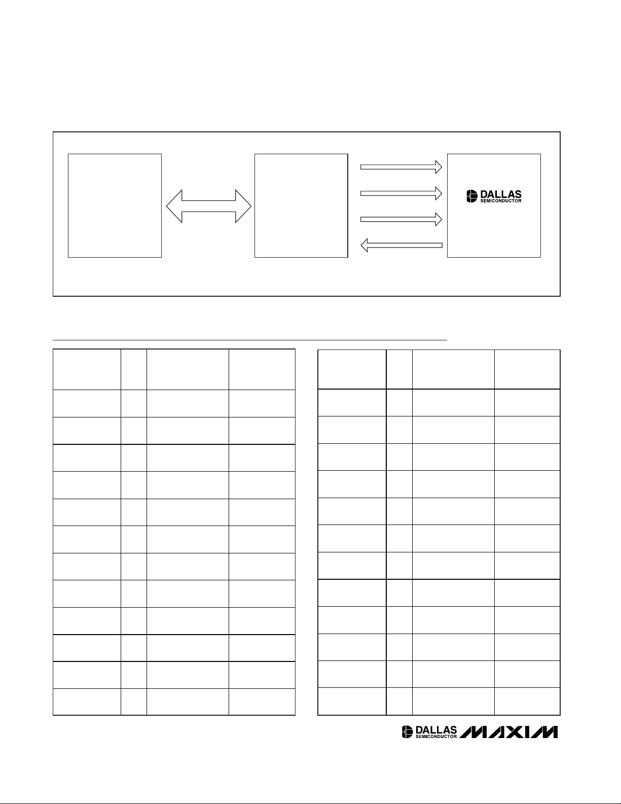
TEST MODE SELECT
JTAG/TAP
INTERFACE
RS-232
INTERFACE
SERIAL-TO-JTAG
INTERFACE
ADAPTER
WINDOWS
PC
SERIAL
(COM)
PORT
TEST CLOCK
TEST DATA IN
TEST DATA OUT
MAXQ3210
Figure 2. Serial-to-JTAG Interface
Component List
DESIGNATION
QTY
DESCRIPTION
SUPPLIER/
PART
NUMBER
C1, C2, C3
10µF, 20V tantalum
capacitors
Panasonic
ECS-T1DX106R
C4
Empty capacitor
footprint (0805)
—
C5, C6
22pF ±10%, 10V
capacitors (0805)
Generic
C7, C8
100nF ±10%, 10V
capacitors (0805)
Generic
C9
2nF, 10V capacitor
(0805)
Generic
D1, D2, D3
Red surface-mount
LEDs
Dialight
597-3001-1xx
JU1, JU3–JU13
2-pin NO (1 x 2,
0.1”) jumpers
3M
929834-02-02
JU2
3-pin NO (1 x 3,
3M
929834-02-03
J1
9V battery clip
Keystone
1294
J2
DC power jack
(2mm)
CUI Inc.
PJ-002A
J3
2 x 5, 0.100”
spaced header
3M
929836-02-05
J4
2 x 20, 0.100”
spaced header
3M
929836-02-20
DESIGNATION QTY DESCRIPTION
SUPPLIER/
PART
NUMBER
3
1
2
2
1
3
12
1
0.1”, 2 of 3) jumper
1
1
1
1
PT1 1
R1 1
R2 1
R3 1
R4, R5 2
R6 1
R7 1
R8, R9, R10 3
R11, R12, R13 3
R14 1
SW1, SW2 2
TP1, TP2, TP3 3
Piezoelectric horn
(high volume)
1.2kΩ, 1/8W
resistor (0805)
510Ω, 1/8W resistor
(0805)
Empty resistor
footprint (0805)
1kΩ, 1/2W resistors
(2010)
68kΩ, 1/8W resistor
(0805)
470kΩ, 1/8W
resistor (0805)
10kΩ, 1/8W
resistors (0805)
1kΩ, 1/8W resistors
(0805)
30kΩ, 1/8W resistor
(0805)
S P S T- N O m om entar y
p ushb utton
1 x 2 (0.100”
spaced) test points3M929834-02-02
CUI Inc.
CEP-1172
Generic
Generic
—
Generic
Generic
Generic
Generic
Generic
Generic
Omron
B3FS-1000

_____________________________________________________________________ 3
Detailed Description
This evaluation kit must be used with the following documents:
• MAXQ3210 Data Sheet
(www.maxim-ic.com/MAXQ3210)
• MAXQ Family User’s Guide
(www.maxim-ic.com/MAXQUG)
• MAXQ Family User’s Guide: MAXQ3210/MAX3212
Supplement (www.maxim-ic.com/MAXQ32xxSUP)
The MAXQ3210 EV kit board is fully defined in the
schematics provided in the EV kit CD-ROM. However, a
short description of the major components and connectors of the boards follows.
Power Supplies
There are three ways to set up power supplies when
using the MAXQ3210 EV kit. The two boards that
require power supplies are the MAXQ3210 EV kit board
and the serial-to-JTAG interface board.
Running Both Boards from
Separate Power Supplies
To run each of the boards from its own power supply,
connect supplies as follows.
• Connect a 5V, ±5% regulated DC wall supply (center post positive) to the J2 power plug of the serialto-JTAG interface board.
• Connect a 9V, ±5% regulated DC wall supply (center post positive) to the J2 power plug of the
MAXQ3210 EV kit board, OR insert a 9V battery into
clip J1 of the MAXQ3210 EV kit board.
• Connect a jumper across pins 1 and 2 of jumper
JU2 on the MAXQ3210 EV kit board.
Note: When using two power supplies in this manner, the JU1 jumper on the MAXQ3210 EV kit board
must be DISCONNECTED.
Running Both Boards from a Single Power Supply
If the serial-to-JTAG interface board is being used, a
single power supply can be used to power both boards
as follows.
• Connect a 5V, ±5% regulated DC wall supply (center post positive) to the J2 power plug of the serialto-JTAG interface board.
• Connect the JH3 jumper on the serial-to-JTAG interface board.
• Connect the JU1 jumper on the MAXQ3210 EV kit
board.
• Connect a jumper across pins 2 and 3 of JU2 on the
MAXQ3210 EV kit board.
Note: Do not connect a power supply to the J1 plug
on the MAXQ3210 EV kit when powering the boards
in this manner.
Running the MAXQ3210 EV Kit Board
from a Single Power Supply
If the MAXQ3210 has already been programmed using
the JTAG interface, it is possible to disconnect the serial-to-JTAG board and power up the MAXQ3210 EV kit
board on its own. This simply executes the previously
loaded firmware, with no possibility of in-application
load or debugging.
• Connect a 9V, ±5% regulated DC wall supply (center post positive) to the J2 power plug of the
MAXQ3210 EV kit board, OR insert a 9V battery into
clip J1 of the MAXQ3210 EV kit board.
• Connect a jumper across pins 1 and 2 of JU2 on the
MAXQ3210 EV kit board.
The power pins for the MAXQ3210 EV kit are connected to the on-board power supplies by jumpers as
shown in Table 1.
Evaluates: MAXQ3210
MAXQ3210 Evaluation Kit
Component List (continued)
DESIGNATION
QTY
DESCRIPTION
SUPPLIER/
PART
NUMBER
U1
MAXQ3210 voltage
regulator
microcontroller
MAXQ3210-EJX
U2
MAX5160 digital
potentiometer
MAX5160LEUA
Y1
Citizen
HC49US3.5795
45MABJ
1
1
1 3.5795MHz crystal

Evaluates: MAXQ3210
Additional Hardware Features
Most of the additional hardware on the MAXQ3210 EV
kit, such as the piezoelectric horn, LED and digital
potentiometer, can be enabled or disabled by setting
or removing jumpers. Disabling unused hardware frees
up the associated port pins for other uses.
Using the RC Oscillator Clock Option
To run the MAXQ3210 EV kit using the RC oscillator,
remove the crystal at Y1, close jumper JU3, and populate R3 and C4 with appropriate components. (Refer to
the MAXQ3210 data sheet for appropriate resistor and
capacitor values for a given frequency.)
Because the XT/RC bit in the CKCN register is set to 1
(selecting crystal mode) upon power-up, the MAXQ3210
will always come out of power-up and attempt to run
from an external crystal. If the RC circuit option is populated instead, the crystal oscillator does not start, and the
MAXQ3210 continues running on the internal ring oscillator (approximately 8kHz) until the loaded program
firmware sets the XT/RC bit to 0. If the MAXQ3210 is not
loaded, it continues running from the internal ring indefinitely, which means it is running too slowly to communicate using the standard JTAG firmware.
If this occurs, you can communicate with the slow-running MAXQ3210 by loading the jtag_1kHz.hex file
(provided on the EV kit CD-ROM) into the serial-toJTAG board and then using MTK or MAX-IDE as usual.
Note that this version performs the master erase, loading, and debug operations much more slowly than
usual due to the reduced communications speed, so as
soon as you have loaded program firmware into the
MAXQ3210 that sets the XT/RC bit to 0 upon startup,
you can reload the normal serial-to-JTAG board
firmware to go back to normal tools operation.
MAXQ3210 Evaluation Kit
4 _____________________________________________________________________
JUMPER
EFFECT
JU1
REGOUT is not connected to JTAG
5V. (Drive from internal regulator or
bench supply.)
*
JU1
Pins 1 and 2
REGOUT is connected to the 5V
supply from the JTAG board.
JU2
The power supply at J2 is not used.
JU2
Pins 1 and 2
The J2 power supply (which should
be 9V) is connected to the V
BAT
pin.
This configuration should only be
used with the J1 battery clip empty.
JU2
Pins 2 and 3
The J2 power supply (which should
be 5V) is connected to the REGOUT
pin. When using this configuration,
the JU1 jumper must be
disconnected and the J1 battery clip
must be empty.
Table 1. Power-Supply Jumper Settings
JUMPER
WHEN OPEN WHEN CLOSED
JU3 No effect.
The RC oscillator circuit may
be used to drive the
MAXQ3210 clock. To use this
feature, Y1 must be empty, and
R3 and C4 must be populated
with appropriate components.
JU5, JU7,
JU8
The piezoelectric
The piezoelectric horn is
enabled.
JU4, JU6
The piezoelectric
horn operates at
The piezoelectric horn
operates at full volume.
JU9 No effect.
Port pin P0.0 is connected to
pin CS of the MAX5160 digital
potentiometer.
JU10 No effect.
Port pin P1.5 is connected to
pin INC of the MAX5160 digital
potentiometer.
JU11 No effect.
Port pin P0.5 (comparator
input) is connected to the
wiper pin of the MAX5160.
JU12 No effect.
Port pin P1.6 is connected to
pin U/D of the MAX5160 digital
potentiometer.
JU13 No effect.
Port pin P0.7 (LED drive) is
connected to the red LED D3.
Table 2. Other Jumper Settings
* Refer to the MAXQ3210 data sheet for the allowable range of
supply at REGOUT.
SETTING
(No jumper)
connected
(No jumper)
connected
connected
horn is disabled.
reduced volume.

_____________________________________________________________________ 5
Evaluates: MAXQ3210
MAXQ3210 Evaluation Kit
WINDOWS PC
WITH SERIAL
(COM) PORT
(USER SUPPLIED)
POWER SUPPLY
5V DC ±5%
> 300mA
(USER SUPPLIED)
POWER SUPPLY
6V–9V DC
> 300mA
(USER SUPPLIED)
(WHEN NOT USING
JTAG BOARD)
RS-232
J1
SERIAL
JTAG
CONNECTOR
SERIAL-
TO-
JTAG
INTERFACE
BOARD
JTAG
INTERFACE
JTAG
CONNECTOR
J2
P2
J2
SW1 SW2
J4
DEVICE
HEADER
PINS
INTERRUPT RESET
CRYSTAL
9V BATTERY CLIP
PIEZO BUZZER
J3
+5V
GND
PROTOTYPE
AREA
MAXQ3210
Figure 3. MAXQ3210 Evaluation Kit Functional Layout

6 _____________________________________________________________________
Evaluates: MAXQ3210
MAXQ3210 Evaluation Kit
1
TP1
GND
PJ-002A
J2
IN
G1
G2
JU2
JU3
JU2 - 1/2 FOR 9V DC POWER
JU2 - 2/3 FOR 5V DC POWER
CLOSE JU3 AND POPULATE R3, C4
TO USE RC RELAXATION OSCILLATOR
VBAT
VBAT
VCC5
VBAT
VCC5
RED LED
D1
C3
10µF
20V
C1
10µF
20V
R1
1.2kΩ
2
1
TP2
VBAT
2
1
1
1
1
2
1
2
2
VCC5
VCC5
RED LED
D2
C2
10µF
20V
R2
510Ω
R3
EMPTY
C4
EMPTY
1
TP3
+5V
2
1
J1
9V BATTERY CLIP
2
1
2
1
1
2
1
2
2
PLUS
MINUS
1
J3
J4
JU1
HEADER 2x5 (JTAG)
HEADER 2x20
3
5
7
9
2
4
6
8
10
TCK
TDO
TMS
CLOSE JU1 TO POWER (5V ONLY)
OVER JTAG CONNECTOR
KEY
TDI
GND
P14_TDO
P13_TCK
P12_TMS P11_RST
P10_TDI
2
1
P0.4_VREF
3
P0.3_CMPO
4
P0.2_T2P
5
P0.1_T2PB
6
P0.07P1.68P1.5
9
P1.4_TDO
10
11
12
232422
21
20
19
18
17
16
15
14
13
315
7
9
11
131517
19
21
232527
29
31
33
35
37
39
426
8
10
12
141618
20
22
242628
30
32
34
36
38
40
P1.3_TCK
P0.0
P0.1_T2PB
P0.2_T2P
P0.3_CMPO
P0.4_VREF
P0.5_CMPI
P0.6_INT
P0.7_LED
P1.0_TDI
P1.1_RESET
P1.2_TMS
P1.3_TCK
P1.4_TDO
P1.5
P1.6
HORNS
HORNB
FEED
P0.4_VREF
GND
P0.3_CMPO
P0.2_T2P
P0.1_T2PB
P0.0
P1.6
P1.5
P1.4_TDO
P1.3_TCK
HFXIN
HFXOUT
P0.6_INT
P0.5_CMPI
P0.7_LED
P0.0_TDI
P1.1_RESET
P1.2_TMS
REGOUT
V
DD
HORNS
GND
HORN
HORNB
FEED
REF
RST
VCC5
GND
3
2
221
3
VBAT
1
1
1
2
2
C6
22pF
10V
C5
22pF
10V
11
1
2
C7
100nF
10V
1
2
VCC5
C8
100nF
10V
1
2
2
2
Y1
3.5795MHz
SOCKETED
2
P0.6_INT
P0.5_CMPI
P0.7_LED
P0.0_TDI
P1.1_RESET
P1.2_TMS
VCC5VBAT
HORNS
HORNB
FEED
MAXQ3210
Figure 4. MAXQ3210 Evaluation Kit Power Schematics

Evaluates: MAXQ3210
MAXQ3210 Evaluation Kit
Maxim cannot assume responsibility for use of any circuitry other than circuitry entirely embodied in a Maxim product. No circuit patent licenses are
implied. Maxim reserves the right to change the circuitry and specifications without notice at any time.
Maxim Integrated Products, 120 San Gabriel Drive, Sunnyvale, CA 94086 408-737-7600 _____________________ 7
© 2006 Maxim Integrated Products is a registered trademark of Maxim Integrated Products, Inc.
is a registered trademark of Dallas Semiconductor Corporation.
INTERRUPT
SW1
JU4
P0.6_INT
HORNS
FEED
3
4
2
VCC5
P.05_CMPI
VCC5
JU9
JU11
JU10
JU12
11
22
2
1
P0.0
P1.5
P1.6
CLOSE JU9, JU10, JU11, JU12 TO
SET COMPARATOR INPUT TO
ADJUSTABLE DIGITAL POT VALUE
CLOSE JU5, JU7, JU8 TO ENABLE PIEZO HORN
CLOSE JU4, JU6 TO ENABLE LOUD VOLUME
CLOSE JU13 TO DRIVE LED WITH P0.7
1
1
2
JU7
R5
1kΩ
1/2W
R6
68kΩ
R14
30kΩ
C9
2nF
CEP-1172
PT1
1
2
1
2
JU6
1
HORNB
2
1M
F
G
122
21
3
1
2
R7
470 kΩ
1
2
R4
1kΩ
1/2W
1
2
1
2
JU5
1
2
JU8
1
2
7
8
VDD
H
L
W
CS
INC
U/D
GND
1
5
6
2
1
2
4
2
2
1
2
1
2
1
2
11 2
R11
1kΩ
R13
1kΩ
RED LED
R10
10kΩ
R9
10kΩ
R8
10kΩ
P0.7_LED
RESET
SW2
P1.1_RST
3
4
2
11 2
R12
1kΩ
MAX5160LEUA
U2
JU13
VCC5
Figure 5. MAXQ3210 Evaluation Kit Demo Components Schematic

Mouser Electronics
Authorized Distributor
Click to View Pricing, Inventory, Delivery & Lifecycle Information:
Maxim Integrated:
MAXQ3210-KIT
 Loading...