

Page 1
DA-LITE SCREEN COMPANY, INC.
3100 North Detroit Street
Post Office Box 137
Warsaw, Indiana 46581-0137
Phone: 574-267-8101
800-622-3737
Fax: 574-267-7804
www.da-lite.com
e-mail: info@da-lite.com
POWER
PRESENTATION PRODUCTS
The
In
Installation and Operating Instructions For
SERIAL CONTROL BOARD SCB-100
Page 2
INSTALLATION
This manual covers installation for both the external SCB-100 and the built-in SCB-100. If you have the external SCB -100,
refer to diagrams 1, 2 and 3 for wire connections. If your screen has the SCB-100 built into the screen case, refer to
diagram 4 for wire connections.
The main power wires (100-240VAC) should always be separated from the low voltage wires. To do this, route the power
and motor wires into the housing using the knockouts on one end of the housing. The wall switch and RS-232 wires
should be routed through the knockouts on the opposite end of the housing.
Do not connect power to the SCB-100 until all other connections are complete.
Wall Switch
The SCB-100 has two manual switch ports. These ports are for dry contact closure only. Port 1 controls motor 1. Port 2
controls motor 2.
1. Install wall switch where desired.
2. Use 3-conductor 20-24 gauge wire to extend the switch wire to the required length.
3. Connect the wall switch to the SCB-100 as shown in diagram 1.
CAUTION: Never apply voltage to the wall switch terminal or the unit will be damaged.
RS-232
The SCB-100 has two RS-232 ports. Port 1 and Port 2 can control either motor 1 or 2.
Both ports are marked with RX, G, TX.
RX-data being received into the SCB-100.
TX-data going out of the SCB-100.
G-ground.
12VDC Out
The SCB-100 supplies voltage to the optional NET-100 network adaptor. The center terminal is not used.
▲
!
1
12VDC OUT FOR OPTIONAL
NET-100 NETWORK
ADAPTOR
Diagram 1
WALL SWITCH 1
RED - UP
BLACK - DOWN
WHITE - COMMON
WALL SWITCH 2
RED - UP
BLACK - DOWN
WHITE - COMMON
RS-232 PORT 1
RX - DATA IN
G - GROUND
TX - DATA OUT
RS-232 PORT 2
RX - DATA IN
G - GROUND
TX - DATA OUT
Page 3

Screen Motor
The SCB-100 has two motor outputs. This allows control of two screens or a screen and a projector lift independently.
1. Connect the motor wires in the screen junction box to the SCB-100 as shown in diagram 2.
2. Use 14-18 gauge wire to extend the motor wire to the required length.
Power Source
1. Connect power wires to the SCB-100 as shown in diagram 3.
2. Connect the building ground wire to the ground lug on the metal housing.
Diagram 2
SCREEN #2
OR
PROJECTOR
LIFT
SCREEN #1
WHITE - COMMON
BLACK - DOWN
RED - UP
WHITE - COMMON
BLACK - DOWN
RED - UP
Diagram 3
SOURCE INPUT
100-240 VAC
GREEN - GROUND
BLACK - HOT
WHITE - COMMON
2
INSTALLATION
SOURCE INPUT
100-120 VAC
SCREEN #2
OR
PROJECTOR
LIFT
SCREEN #1
BLUE - COMMON
BROWN - DOWN
BLACK - UP
BLUE - COMMON
BROWN - DOWN
BLACK - UP
SOURCE INPUT
240 VAC
Page 4

Printed in U.S.A. 93489 Rev. 11/04
3
RS-232 Communications
The command protocols are as follows.
Screen 1 up: @1U
Screen 1 stop: @1S
Screen 1 down: @1D
Screen 2 up: @2U
Screen 2 stop: @2S
Screen 2 down: @2D
Poll: @P
Response to a poll is @1x2x where x is U for up, S for stop, D for down.
Communications is 9600 baud, 8 data bits, No parity, 1 stop bit.
No “Return” or “Enter” is required at end of string. The command will be executed as soon as the U, D, or S is received.
There is a 50ms time out if a valid character is received but the string is not finished. All command characters must be
sent in one packet.
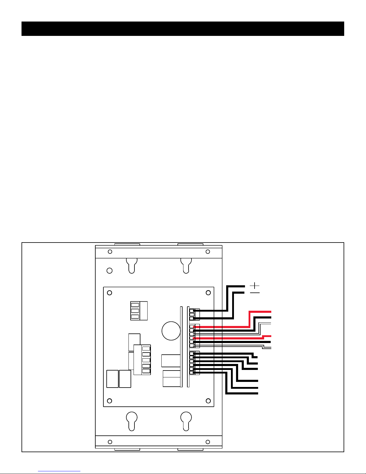
Built-In SCB-100 Control
Locate the 11-pin connector in the junction box of the screen. Refer to diagram 4 for wire connections.
RS-232 Ports
The SCB-100 has two RS-232 ports. Both ports have three wire connections.
RX-Data being received into the SCB-100.
TX-Data going out of the SCB-100.
G-Ground.
Wall Switch
The wall switch terminal is a dry contact closure. Do not apply voltage to this terminal or the control will be damaged.
1. Install the wall switch where desired.
2. Use 3-conductor 20-24 gauge wire to extend the switch wire to the required length.
12VDC Out
The SCB-100 supplies power to the optional NET-100 network adaptor. If you are using the NET-100 adaptor, connect the
power wire from the NET-100 to the 12VDC output terminal.
INSTALLATION
1234567891011
1234567891011
RX-DATA IN
G-GROUND
TX-DATA OUT
RX-DATA IN
G-GROUND
TX-DATA OUT
WHITE-COMMON
BLACK-DOWN
RED-UP
+
12VDC OUT
TERMINALS 1-3 = RS232 PORT 2
TERMINALS 4-6 = RS232 PORT 1
TERMINALS 7-9 = WALL SWITCH
TERMINALS 10-11 = NET-100 CONTROLLER
 Loading...