

Page 1

INSTRUCTION BOOK FOR
Computer Table Netbook Storage Cart
CTNS42
Page 2
Tools Required for Installation
CAUTION! The user of this product should exercise
caution when moving the cart. Any sudden stop could
cause instability of the cart and could cause serious injury
and/or damage. The cart should always be pushed, never
pulled, by the user. Always push from the side of the cart,
never from the front or back of the cart. This cart is
rated 115 VAC, 60 Hz 12 A.
Required Tools:
- Phillips screwdriver
- 3/8” end wrench
- 7/16” end wrench
- 1/2” end wrench
Listed Accessory – The CTNS42 is intended for use with Listed
Information Technology Equipment.
The power cord is the disconnect device. The socket-outlet shall
be installed near the equipment and shall be easily accessible.
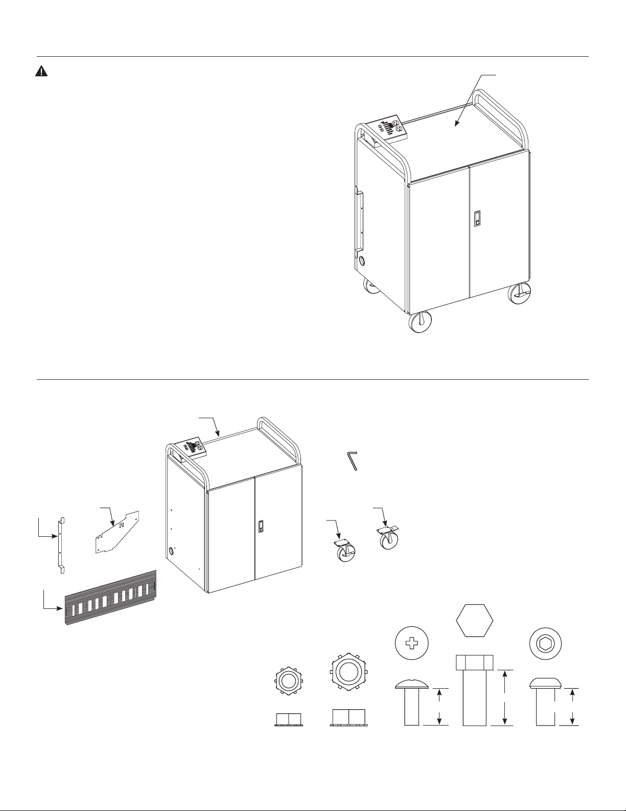
Maximum Load Per
Shelf Is 60 Pounds
(Four Shelves)
Suggested Methods of Installation
1. Remove contents from carton and examine.
4
1
3
2
Item Description Qty
1 Cord Wind Bracket 1
2 Divider 39
3 Vinyl Mat 3
4 Cart Assembly 1
F
6
5
5 Caster, Plate 5" W/B 2
6 Caster, Plate 5" W/ Swivel Lock 2
Package Set 1
A Nut, Hex #1024 4
B Nut, Hex 1/4"-20" 2
C Screw, Mach #1024 x 1/2" 4
D Screw, HHCS 5/16"-18 x 3/4" 16
E Screw, BHSCS 1/4"-20 x 1/2" 4
F Wrench, Allen 5/32" 1
0.75
BA
2
C D E
0.500.50
Page 3
Suggested Methods of Installation (Continued)
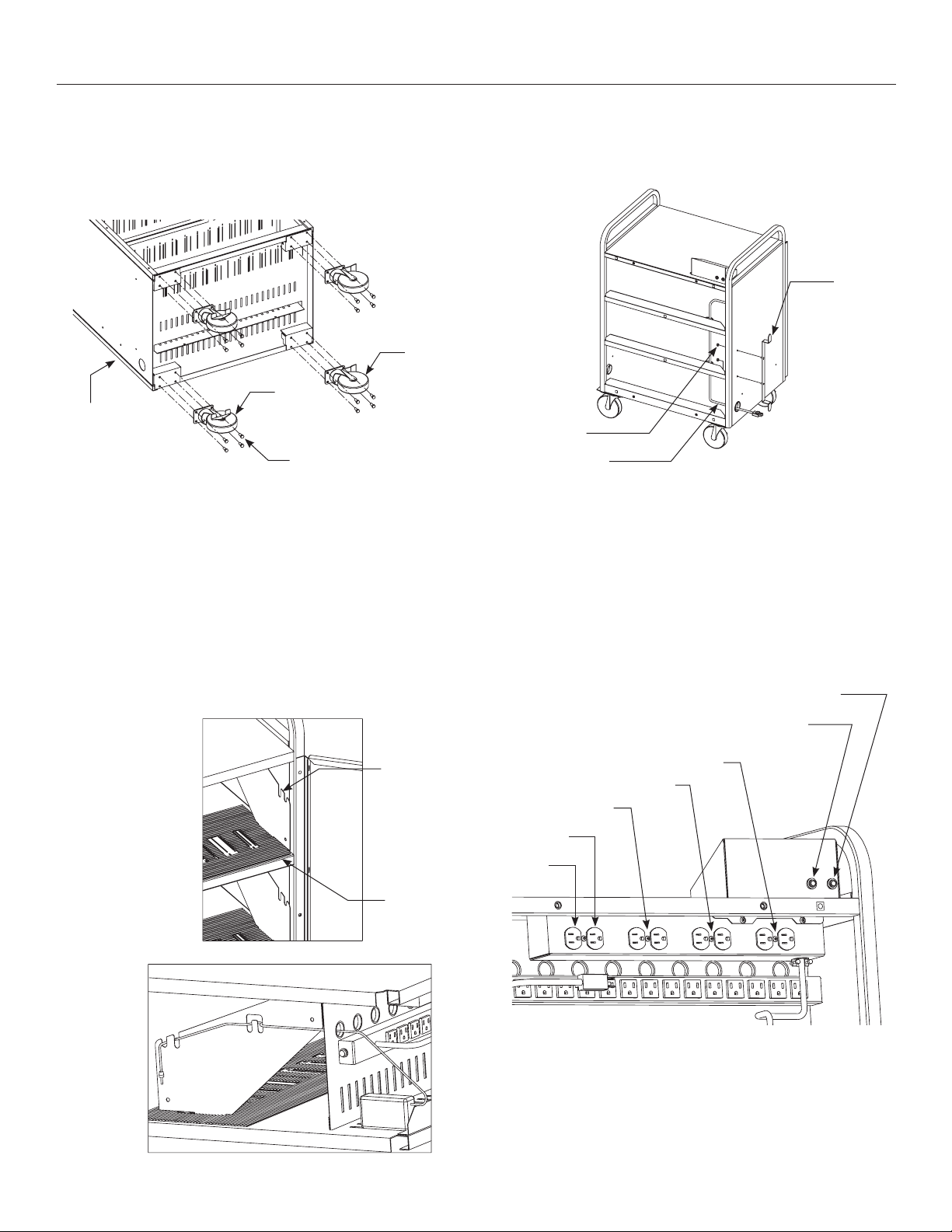
2. Lay cart onto rear panel. See Figure 1. Install Plate Casters. Two
casters have wheel brakes and two casters have swivel locks.
Install both wheel brake casters on one end and both swivel lock
casters on the other end. It does not matter onto which end
either pair of casters is mounted. Tighten all fasteners.
6
5
4
Figure 1
D
3. The Mats and some Dividers were installed at the factory. Install
the rest of the Dividers into cart. See Figure 2. Place the Dividers
into the slots marked for your desired coniguration of cart. Slots
marked with a round hole are for holding 42 netbooks. Slots
marked with a rectangular hole are for holding 36 netbooks. Slots
without markings are for holding 33 netbooks. Store any left-over
Dividers according to Step 9. Install Divider by inserting top rear
portion of Divider irst and then lowering front Divider tab into
shelf. It will be easiest to install the netbook charger as the Divider
is installed. See Figure 3.
4. Remove rear panel by turning the fasteners 1/4 turn in either
direction. Route the Power Cord through the shelves and out
through either side. See Figure 4. Install Cord Wind Bracket on
same side as the exiting Power Cord.
1
B
Power Cord
Figure 4
5. The Circuit Breaker reset buttons and the output receptacles of
the power distribution device are shown. See Figure 5. The Extra
Receptacle is always powered as long as the ON/OFF switch is
ON and the cart is plugged into a powered receptacle. The Extra
Receptacle has a maximum rating of 1 ampere. It could be used
for a wireless router. If either one of the two Circuit Breaker reset
buttons are extended, push to reset the circuit breaker after it
cools down for 45 seconds. The fan is only on when charging
occurs in the cart.
Fan Circuit Breaker (1A)
Figure 2
Figure 3
Extra Circuit Breaker (1A)
2
Bottom Shelf
Middle Shelf
Top Shelf
Extra
(Router)
Fan
3
Figure 5
3
Page 4

Suggested Methods of Installation (Continued)
6. The control panel is shown. See Figure 6. The ON/OFF switch is
also a 15A circuit breaker. The Arrow Keys allow you to select the
Mode. If you want to use the Auxiliary Receptacles, push the
Arrow Keys to select the Auxiliary Mode. No netbook charging
occurs when the Auxiliary Mode is selected. The Auxiliary
Receptacles are rated for 120VAC, 12A. Select another MODE to
turn the Auxiliary Receptacles of. If electrical power is interrupted
when the ON/OFF switch is ON, the power distribution device will
remember what it was doing when the power was lost and will
resume the last command when power is restored.
Arrow Keys
3 Shelf Status
(Green, Yellow, Or Red)
Indicator Lights
Auxiliary
Receptacles
On/Of Switch
7 Mode (Yellow)
Indicator Lights
Figure 6
7. Important requirements for proper cart operation.
a) Recharge Lithium-Ion batteries only.
b) All computers being charged need to be turned of or put
into sleep mode.
c) Do not add computers to the cart after the charging cycle
has started. Restart the charge cycle if computers need to be
added.
8. Typical cart operation.
a) Install netbook chargers. Route cords per Figure 3.
b) Turn of netbook computers.
c) Place netbook computers into cart.
d) Attach charging cords to netbook computers.
e) Plug cart’s electrical cord into 15 ampere 120VAC wall socket.
f) Turn cart power ON with rocker switch.
g) Use arrow keys to select desired MODE. Wait for short time
delay for operation to start.
h) When the cart is inished charging, the cart will go to HOME
MODE. To start charging the next time, push the ARROW
DOWN button once to select CHARGE MODE.
Mode Description
Mode Operation Performed Unique Operation This Mode Performs
Charge Charges All Computers Charges Quickest And Is Most Energy Conservative
Top Charges All Computers Charging Priority Given To Top Shelf
MID Charges All Computers Charging Priority Given To Middle Shelf
BOT Charges All Computers Charging Priority Given To Bottom Shelf
Maintain Charges All Computers
Auxiliary Powers Control Panel Receptacles No Charging Occurs
Home Low Energy Usage Rest Mode
Keeps Batteries Charged During Extended Periods (Vacations).
Charges Once Every Four Days
Shelf Status Description
Shelf Status
Indicator Color Meaning
Green Indicated Shelf (Top, Middle, Or Bottom) Is Charged
Yellow Indicated Shelf (Top, Middle, Or Bottom) Is Charging
Solid Red
Flashing Red Indicated Shelf (Top, Middle, Or Bottom) Used 11 AMPS Or More (An Indication Of A Serious Situation)
Indicated Shelf (Top, Middle, Or Bottom) Is Not Behaving As Expected. Charging Current Has Either Increased Or Has Not
Decreased AS Expected Since Charging Began. A Computer May Have Been Added After Charging Began, A Computer May
Have Been Left On Or Battery Failure May Have Occurred Are Possible Explanations.
4
Page 5

Suggested Methods of Installation (Continued)
9. You may experience problems when charging if only a few
computers are on one shelf, especially if they are only partially
discharged. The computers may not draw enough electrical
current to indicate to the power distribution device that there are
computers on the shelf. There are solutions to this problem.
Charging Solutions
Time Frame For A Few
Computers On One Shelf Solution
Short Term
Medium Term
Long Term
Discharge Computer Batteries Fully Before Recharging
Use "Top", "MID", Or "BOT" Mode To Charge Computers
Mix Partially Discharged Computers On Another Shelf
Use "Top", "MID", Or "BOT", Mode To Charge Computers
Plug "Problem Shelf's" Power Strip Into Another Shelf's Receptacle
Plug Another Shelf's Power Strip Into "Problem Shelf's Receptacle
Spread Computers Equally Among The Shelves
Use "Top", MID", Or "BOT" Mode To Charge Computers
10. Store left-over Dividers for future use by attaching them to the
inside of the cart with the fasteners shown. See Figure 7.
2
C
Figure 7
A
CAUTION! The CT-NS42 is intended for use with a maximum
weight per shelf of 60 pounds. Use with products heavier
than the maximum weights indicated may result in
instability causing possible injury.
11. For theft deterrence, use the Screws shown in addition to the 1/4
turn fasteners. See Figure 8.
Figure 8
E
Page 6

Page 7

Page 8

A Milestone AV Technologies Brand
3100 North Detroit Street
Warsaw, Indiana 46582
P: 574.267.8101 or 800.622.3737
F: 574.267.7804 or 877.325.4832
E: info@da-lite.com
www.da-lite.com
DL–0388 6.14
© 2014 Milestone AV Technologies LLC. Printed in U.S.A.
E-486
 Loading...